

Page 1
V
OSOSTESLÖ
S
TUSGENO
A
EMAIN
S
N
R
-
ÓN
L
U
R
E
J
S
S
D
L
D
I
L
R
T
U
I
R
A
0
A
R
T
A
O
0
O
O
1
W
1
U
3
V
2
0
0
/
V
W
TS
S
LDERI
LDEE
ATION
TACI
T-ENT
E
TAÇÃO
S
ACJA L
D3
G & DE
EN DE
DE SOU
DE SO
ÖTSTAT
DE SOL
TOWN
OLDER
OLDEE
AGE &
DADUR
ION - 1
ADUR
CZA Z
NG ST
STATIO
DESSOU
Y DES
0W/23
E DESS
OZLUT
TION N - 100
DAGE -
LDADU
V
LDAD
WNICĄ
00W/2
/230
00 W/
RA - 10
RA - 10
- 100W
0V
30 V
W/230
W/230
230V
ER MAN
BRUIKE
TICE D’
M
NUAL D
B
DIENUN
NUAL D
STRUKC
UAL
SHAND
MPLOI
EL USUA
GSANLEI
O UTILIZ
A OBSŁ
EIDING
IO
UNG
ADOR
GI
10
16
23
29
36
42
4
Page 2
VTSSD3
08.02.2010 ©Velleman nv
2
Page 3
VTSSD3
Figure 1
08.02.2010 ©Velleman nv
3
Page 4
1
.
oImIf
.3.
e
u
uwas
u
e
c
r
I
e
ove
osoIn
rpr
eca
V
a
h
a
n
n
e
V
s
h
i
n
a
v
e
o
n
s
n
n
n
e
e
.
h
t
.
i
e
o
o
s
c
m
m
e
e
o
a
e
g
p
r
m
o
u
s
o
a
n
.
a
m
e
e
h
c
s
e
a
e
u
c
o
s
h
o
p
i
n
e
o
u
s
o
d
d
d
e
y
e
e
t
a
n
n
e
t
t
y
c
p
e
o
.
y
d
t
s
o
r
n
s
r
y
R
b
n
e
m
u
l
D
c
e
,
r
y
n
s
p
a
e
d
o
O
b
r
p
s
e
h
w
e
e
s
m
e
d
u
o
v
a
e
n
e
t
m
a
a
u
n
c
h
g
e
d
c
n
g
n
e
Introd
T
all reside
portant e
in doubt,
Th
ank you fo
rvice. If the
se
Th
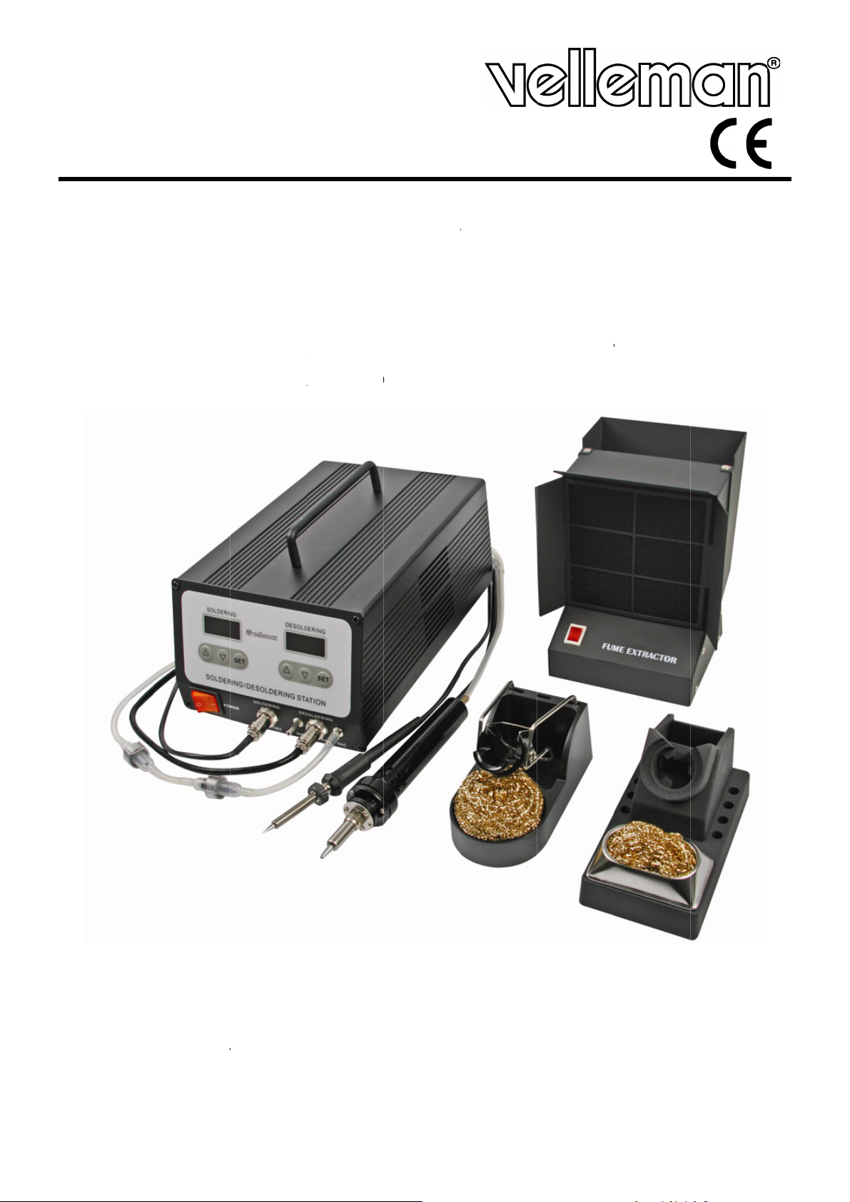
e VTSSD3
2
1x
1x
1x
1x
1x
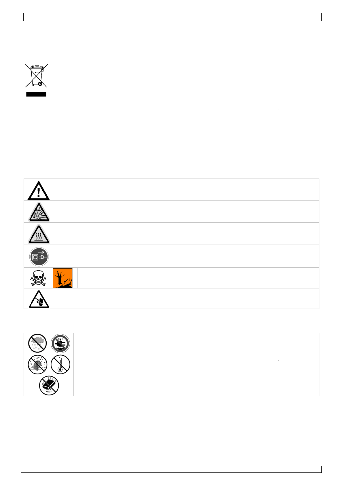
Safety
ction
nts of the
nvironme
Thi
s symbol o
co
ld harm th
te; it shou
ret
rned to yo
rul
s.
ontact yo
choosing
device wa
comes wit
soldering/
soldering
desolderi
fume extr
cleaning s
nstruct
European
tal infor
the devic
environm
ld be taken
ur distribut
ur local w
elleman! Pl
damaged i
:
desolderin
ron + tip a
g iron + ti
ctor
et
ions
Us
Union
ation abo
or the pa
nt. Do not
to a specia
r or to a l
ste dispo
ase read t
n transit, d
station +
nd stand w
and stand
VTSSD3
r man
t this pro
kage indica
dispose of
lized comp
cal recycli
al author
e manual t
not install
ower cord
th tip clea
with tip cl
ual
duct
tes that di
the unit (o
ny for rec
g service.
ities.
horoughly
or use it a
er
aner
posal of th
batteries)
cling. This
espect the
efore bring
d contact y
device aft
as unsorte
evice sho
local envir
ing this de
ur dealer.
r its lifecy
municipal
ld be
nmental
ice into
le
Genera
R
fer to the
K
D
D
Al
a
N
ep this de
not use n
ntilated ro
not touch
ldering iro
correct u
ways disco
e performe
otect agai
Do
with
ver use th
pacitors ar
l Guideli
elleman®
Indoo
liquids
ice away f
ar inflam
ms.
the shaft
to its stan
e may ca
nect main
d. Handle t
st damage.
ot inhale s
local regul
device on
discharge
nes
Service a
r use only
Never put
om childre
able produ
r (de)solde
d between
se fire.
power wh
he power c
Have an a
lder fume
tions.
live electr
d.
d Quality
Keep this
object fille
and unau
cts or in ex
ring tip as
uses; alwa
n the devi
rd by the
thorised d
. Dispose
nic circuits
Warranty
evice awa
with liqui
horized us
plosive at
his can ca
s let it coo
e is not in
lug only.
aler repla
f fume filte
Make sur
on the last
form rain
on top.
rs.
ospheres.
se serious
down afte
use or whe
o not crim
e it if nece
rs and sold
power to t
pages of t
moisture,
nly use in
urns. Alw
use and b
n maintena
the power
sary.
residue i
he work pi
is manual.
splashing a
properly
ys return t
fore stora
nce activiti
cord(s) an
accordan
ce is cut a
nd dripping
e
e.
s
e
d
Keep t
•
Familiarise
•
All modific
to the devi
Only use t
•
warranty.
Damage c
•
the dealer
•
Do not swi
the device
08
.02.2010
are cle
Protec
device
yourself w
tions of th
ce is not c
e device f
used by di
will not ac
tch the dev
against da
is device
ar at all ti
this devic
th the func
device ar
vered by t
r its intend
regard of
ept respon
ice on imm
age by le
way from
es.
from shoc
tions of th
forbidden
e warrant
ed purpose
ertain guid
ibility for a
diately aft
ving it swi
ust and ex
ks and abu
device bef
for safety
.
. Using the
lines in thi
ny ensuing
r it has be
ched off u
4
reme heat.
e. Avoid b
re actuall
easons. Da
device in a
s manual i
defects or
en exposed
til it has re
Make sure
ute force
using it.
mage caus
unauthori
not cover
roblems.
to change
ched roo
the ventila
hen operat
d by user
sed way wi
d by the w
in temper
temperat
ion openin
ing the
odificatio
ll void the
rranty and
ture. Prot
re.
©Vellema
s
s
ct
nv
Page 5

VTSSD3
4. Features
• HEATER/SENSOR FAILED DETECTION: if the sensor circuit fails, the display reads “S--E” and heater
power is cut. If heater circuit fails the display will read “H--E” and heater power is cut.
• TEMPERATUE “LOCK-OUT” FEATURE: the temperature can be locked with a password which might be
useful in a production line.
• ESD SAFE AND SPIKE FREE CIRCUITRY: the “Zero Voltage” electronic switching design also protects
voltage and current sensitive components (CMOS devices, etc.) against overcurrent and transient
voltage spikes.
• DELAYED SUCTION: to eliminate the problem of solder clogging up the tip, a delayed switch feature
has been incorporated for the unit that allows the pump to continue sucking for 1.5 seconds after the
control switch is released.
• LIGHTWEIGHT SOLDERING IRON: ergonomic mini handle that stays cool and prevents operator
fatigue.
• ENERGY SAVE MODE: If the station has been idle for 20 minutes, the energy saver feature will
automatically bring the temperature down to 150°C. Activating the solder/desolder iron will disengage
the power saving feature and the unit will immediately return to the preset temperature. When no
activity is detected for 40 minutes, the main power will be switched off to lower power consumption
and extends tip life.
Note: switch off the unit and then switch it on again to restart the device.
• IRON WORKING OPTION: Both soldering, desoldering irons can be used at the same time. They can
also be shut off individually to save power.
• isolated power supply: high-quality 32Vac transformer designed for lead-free soldering/desoldering
digital readout for both the soldering and desoldering iron
• temperature stability: tip temperature accurate to within ±3°C (6°F)
• spike-free circuitry: zero voltage switching and fully grounded design make this unit safe on electro
sensitive devices
• electronic temperature control: adjustable temperature without changing tips
• vacuum switch: suction is controlled by a finger-actuated thyristor circuit conveniently located on the
desoldering handle
• iron assemblies: detachable soldering (ergonomic mini handle) and desoldering irons for easy use and
repair
• pump a self-contained diaphragm vacuum pump engineered to provide continuous and maintenance-
free operation
• isolated power supply: high-quality 32Vac transformer, heater and sensor fail detection, energy saving
mode
• standard desoldering tip (incl.): BITDEST2 (1.2mm)
• available options:
o spare desoldering tips: 1.2mm (BITDEST2), 1.0mm (BITDEST3) 1.5mm (BITDEST4)
o spare filter: FILT/DES2
o spare soldering bits: 0.2mm (BITSSC1), 0.5mm (BITSSC2)
o spare desoldering iron: VTSSD3/DESOL
o spare soldering iron: VTSSC7/SP3
o spare cleaning pin: VTSSD/SP2
o barrel and nut assembly for soldering iron: VTSSC7/SP4
o barrel and nut assembly for desoldering iron: VTSSD3/SP2
o desoldering iron heater: VTSSD3/SP1
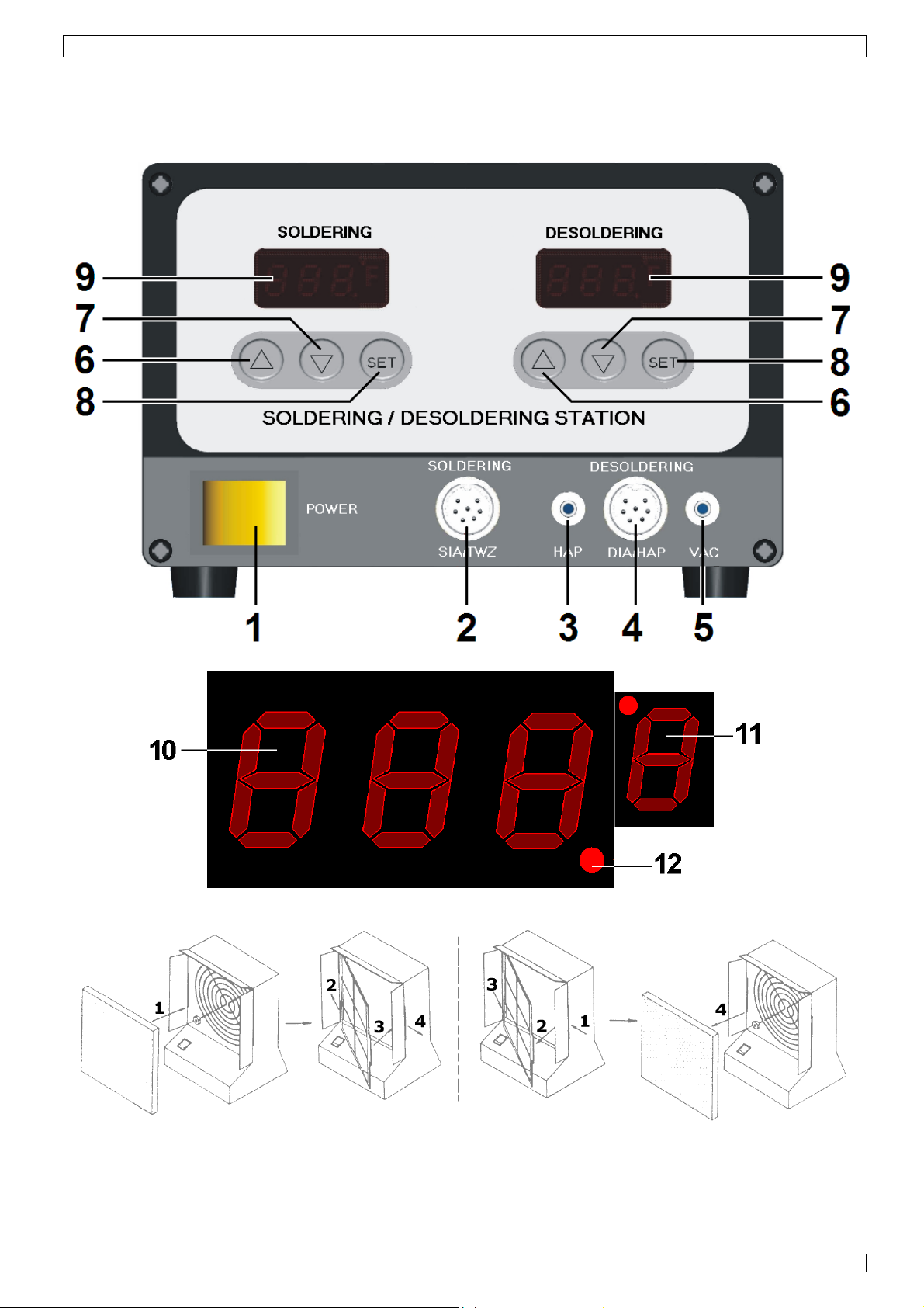
5. Overview
Refer to the illustrations on page 2 of this manual.
1 power switch 7
2 soldering iron connection 8 SET-button
3 hot air connection 9 display
4 desoldering iron connection 10 temperature indication
5 vacuum connection 11 temperature unit (°C or °F)
up-button (▲)
6
down-button (▼)
12 heating indication
08.02.2010 ©Velleman nv
5
Page 6
VTSSD3
6. Description
This soldering/desoldering station is designed to meet the present and future needs of the electronic
production industry. The VTSSD3 is engineered to meet the stringent demands of hobbyists,
maintenance personnel and production people alike.
The VTSSD3 is equipped with a self-contained, electronically controlled vacuum pump. The vacuum
pump is maintenance-free. It will not overload with continuous use. The vacuum pump provides a max.
suction of 50cm/Hg (20"/Hg) and is activated by a push-button switch located on the housing. The solder
collector in the hand-piece can easily be removed for cleaning purposes. The internal aluminium cooling
strip prevents the solder from flowing to the tip too quickly and the ventilation slots keep the handle cool.
The VTSSD3s’ electronic circuitry enables the user to install soldering temperatures between 150 and
480°C (302 to 896°F) and desoldering temperatures between 300 and 450°C (572 to 842°F) without
having to replace the tip or the heating element. The soldering iron contains a highly insulated, Japanesemade ceramic heating element. The desoldering iron is equipped with a precision-wound heating element.
The temperature is maintained to within ± 3°C (± 6°F) of the normal operating temperature through a
PTC sensor (for the ceramic heating element of the soldering iron) and a thermocouple sensor (for the
heating element of the desoldering iron). The heating element heats up very quickly and temperature
corrections are executed swiftly thanks to the exceptionally high maximum temperature. The ergonomic
design and the silicone rubber handgrip improve user comfort.
The revolutionary "zero voltage" switching design also protects voltage- and current-sensitive
components (CMOS devices, etc.) against the damaging current and transient voltage spikes commonly
produced by less efficient, mechanically switched stations. The heating elements are galvanically isolated
from the electrical supply by an isolating transformer that prevents the system from using a max. tension
higher than a (safe) 32VAC. Both the soldering and desoldering iron are equipped with a temperature
control located on the front panel. These controls enable the user to execute rapid and precise
temperature adjustments whenever necessary.
7. Operating Temperature
SOLDERING
The most common soldering alloys used in the electronics industry consist of 60% tin and 40% lead. The
operating temperature of this type of solder is detailed below and can vary from manufacturer to
manufacturer. However, to meet RoHS requirements, these solders are no longer allowed and are
replaced by lead-free solders that require a working temperature which is ±30°C (54°F) higher.
leaded solder lead-free
Melting point 215°C (419°F) 220°C (428°F)
Normal Operation 270-320°C (518-608°F) 300-360°C (572-680°F)
Production Line Operation 320-380°C (608-716°F) 360-410°C (680-770°F)
A good joint is assured if the iron's operating temperature is set within the parameters suitable for the
type of solder being used. The solder will flow too slowly if the temperature is too low; if the temperature
is too high, the flux in the solder may burn which will give rise to billowing white smoke. In turn, this will
result in a dry joint or in permanent damage to the PCB.
DESOLDERING
Recommended tip temperatures are detailed below. They can vary from joint to joint.
For a small joint : 320-360°C (or 608-680°F)
For a larger joint : 370-400°C (or 698-752°F)
If the temperature is too low, the solder will flow too slowly and this may cause the tip to clog; you may
burn the PCB if the temperature is too high.
8. Operating instructions
Refer to the illustrations on page 2 of this manual.
Verify whether the operating voltage of the unit is identical to that of the electrical supply.
GENERAL
• Make sure the unit's power switch [1] is in the "OFF"-position.
• Plug in the soldering [2] and desoldering [4] irons. Note that the connectors have a notch so they
only fit in one way. Do not force.
• Slide the vacuum tube to the VAC-connection [5].
• Connect the AC power cord to the mains outlet.
08.02.2010 ©Velleman nv
6
Page 7
VTSSD3
FUME EXTRACTOR
The device comes with a fume extractor. This extractor should be used at all times when soldering or
desoldering activities are performed.
• Install (or replace) the filter. Refer to the illustration on page 2 of this manual
• Plug the power cord into the back of the fume extractor and plug the other end into a suitable mains
outlet.
• Place the extractor near the working area and switch it on.
PARAMETER SETTINGS
• Switch on the station [1]
• Press the SET-button [8] and hold for at least 5 seconds until the display shows “— — —”
(flashing).Use the ▲-button [6] to enter the mode lock password “010” (default) and press the set-
button [8] to go into setup menu. A wrong password will return to normal working mode (temperature
indication).
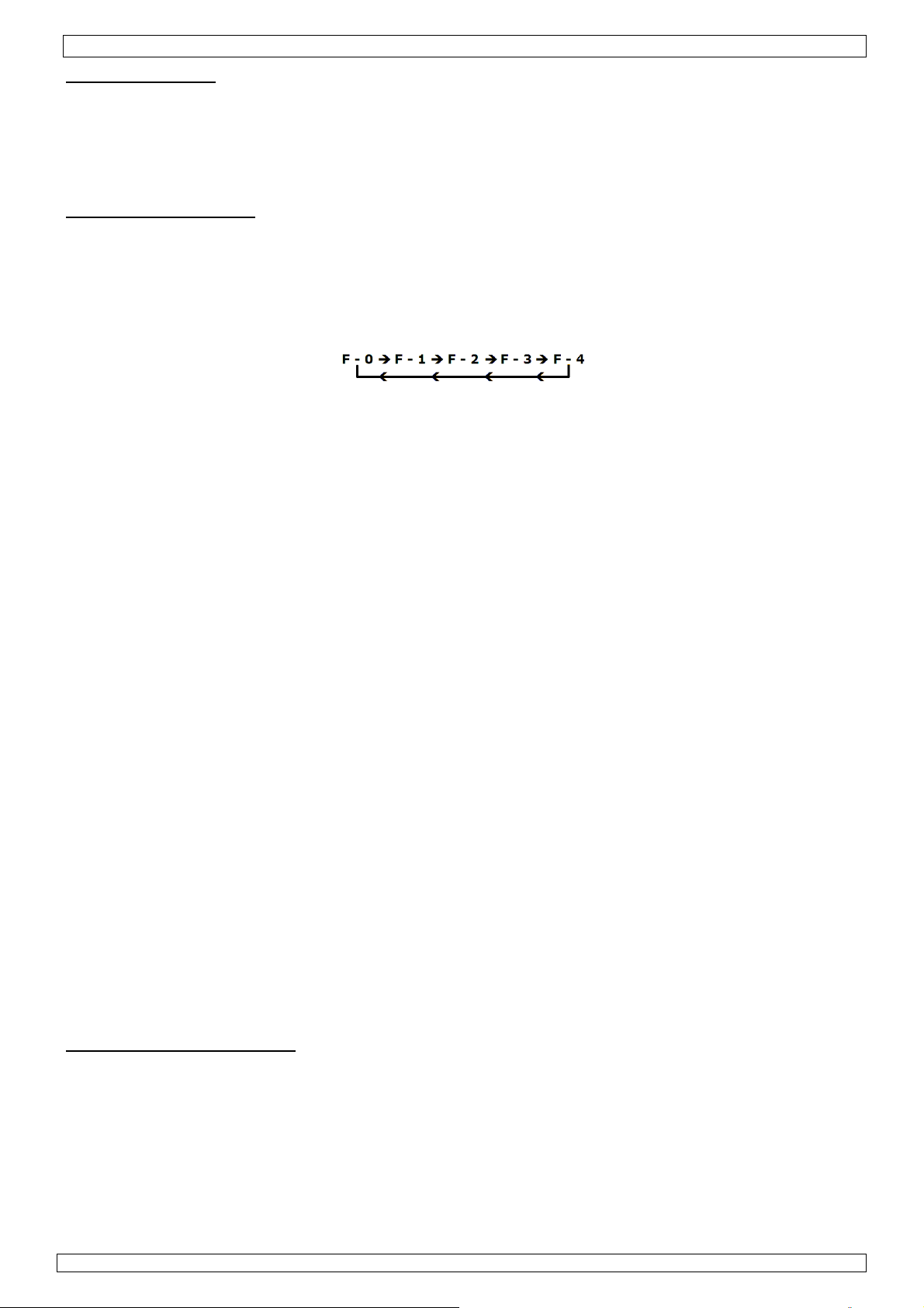
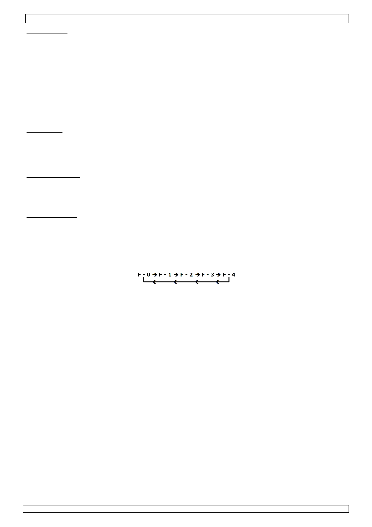
• In the setup menu, the display will show “F-0”. Press the ▲[6]- or ▼ [7]-button to select modes. If
no button is pressed within 15 seconds the device will return to normal operation mode.
• F-0: exit menu mode
Press the SET-button [8] when the display shows F-0 to exit the setup menu and return to
temperature indication.
• F-1: password mode
When password mode is enabled, the user can not change the temperature settings on the station
unless he or she knows the password.
Press the set-button [8] once to enter password mode. Press the ▲[6]- or ▼ [7]-button to change
display between 000 and 100, with 000 indicating password mode disabled and 100 indicating
password enabled. Press the set-button [8] to return to the setup menu.
• F-2: temperature correction mode
Press the set-button [8] once to enter temperature correction mode. Press the ▲[6]- or ▼ [7]-
button to enter a correction factor for the temperature, e.g. when the display shows 300°C but the
actual temperature is only 290°C, add 10°C to the shown correction value.
When in °C negative values are indicated with a minus in front; in °F negative values are indicated
by a blinking display (5s interval). Press the set-button [8] to return to the setup menu.
• F-3: sleep/power off mode
Enabling sleep/power off mode will lower the irons’ temperature after 20 minutes of inactivity. After
±45 minutes of inactivity, the power to the iron is shut off.
Note: sleep/power off mode is set individually for soldering and desoldering iron.
Press the set-button [8] once to enter sleep/power off mode. Press the ▲[6]- or ▼ [7]-button to
change display between 000 and 100, with 000 indicating sleep/power off mode disabled and 100
indicating sleep/power off mode enabled. Press the set-button [8] to return to the setup menu.
When in sleep mode, the temperature is lowered (soldering iron -> 150°C (302°F), desoldering iron
-> 200°C (392°F)) and the display is flashing.
Note: default power save/off mode is disabled.
There are 3 ways to exit sleep mode:
- Soldering iron: shake it gently ; desoldering iron: press the suction button on the iron.
- Press any button under the flashing display.
- Switch the station completely off and on again [1].
Once a device is in power off mode, the display shows a flashing “— — —”. To start the iron again,
press the ▼ [7]-button.
• F-4: unit of temperature
The unit of temperature for the soldering (left) and desoldering display (right) can be set
individually.
Press the set-button [8] once to enter temperature mode. Press the ▲[6]- or ▼ [7]-button to
change between °C and °F. Press the set-button [8] to return to the setup menu.
SOLDERING/DESOLDERING
IMPORTANT NOTE
Do not use temperatures in excess of 410°C (770°F) for normal soldering and desoldering purposes.
The device can be used at higher temperatures for short periods of time. EXERCISE GREAT CAUTION
WHEN DOING SO.
CAUTION
Do not touch the metal parts of the soldering or desoldering iron while the unit is being used or while it
is cooling in order to avoid burns.
1. Place the power switch [1] in the "ON"-position.
2. Press the ▲-button [6] under the soldering display (left) until the display shows 250°C.
08.02.2010 ©Velleman nv
7
Page 8

VTSSD3
Note: press and hold the ▲[6]- or ▼ [7]-button to increase setting speed. While the iron is heating
up, the heating indication [12] flashes.
3. Tin the surface of both the soldering and desoldering tip by applying a new protective layer of solder.
4. Set the irons to the desired temperature.
Note: The soldering and desoldering irons can be used simultaneously.
IMPORTANT DESOLDERING NOTES
(a) Do not activate the vacuum pump until the solder has melted completely. Melting is achieved by
moving the hot tip around the lead, leaving visibly melted solder on the component side of the PCB.
(b) Release the vacuum switch when the tip is completely solder-free, otherwise the tip may clog.
(c) Add solder to the joint of the component and allow the solder to melt completely for improved
desoldering.
(d) Remove the solder collector and clean it after no more than 200 applications. However, daily cleaning
is strongly recommended, especially if the device is used frequently. Refer to §13 & 14.
(e) Replace the cotton pad in the solder collector and the in-line filter when they start to turn yellow.
(f) Use the included spring wire to clean the tip in case of insufficient suction. Also check the in-line
filters.
(g) Make sure that all filters are in place during operation in order to avoid damage to the vacuum pump.
(h) Read "12. Maintenance" when you wish to replace the tip.
9. Common causes for tip failure
• The temperature of the tip exceeds 410°C (770°F)
• The tip is not sufficiently tinned
• Wiping the tip on a surface with a high sulphur content or on a dirty or dry sponge
• Contact with organic or chemical substances such as plastic, resin, silicone and grease
• Impurities in the solder and/or a low tin content
10. Tip maintenance
The soldering and desoldering irons use extremely high temperatures. Make sure that the unit is switched
off for maintenance purposes.
Remove the tip and clean it after heavy or moderate use. We recommend cleaning the tip daily if the
station is used frequently. Remove excess solder in the tip retaining assembly to prevent the tip from
clogging.
The supplied soldering and desoldering tips are made of copper covered with a layer of iron. They will
retain their projected life span if used properly.
• Always tin the tip before returning it to the holder, prior to turning off the station or to storing it for
long periods of time. Wipe the tip on a wet sponge or use our tip cleaner before activating the device.
• Using excessive temperatures (more than 400°C or 750°F) will shorten the life span of the tip.
• Do not exercise excessive pressure on the tip while soldering and/or desoldering, as this may cause
damage to the tip.
• Never clean the tip with a file or with abrasive materials.
• Do not use flux containing chloride or acid. Use only resinous fluxes.
• If an oxide film has formed, you should remove it by buffing carefully with a 600-800 grit emery cloth
or by using isopropyl alcohol and consequently applying a new protective layer of solder.
• Set the desired temperature after allowing the unit to idle at 250°C for three minutes. The station will
be ready for use once the set temperature is reached.
IMPORTANT
Remove and clean the tip daily. Remove excess solder from the barrel nut assembly when installing a
new tip, otherwise the tip may be fused to the heating element or to the retaining assembly.
11. Loss of suction: possible causes
Use the procedure outlined below to determine whether the loss of suction is due to the tip, to the solder
collector, the tube or the in-line filters.
CAUTION: THE MAIN POWER SWITCH SHOULD BE IN THE "OFF"-POSITION BEFORE ATTEMPTING
THESE PROCEDURES. THIS WILL ALLOW THE DEVICE TO COOL.
a) disconnect the vacuum tube from the fitting on the front panel. Place your finger over the hole and
depress the vacuum switch. You should now have a strong vacuum. If not: return the station to the
point of sale to have the pump repaired.
b) disconnect the in-line filters from the iron assembly. Depress the vacuum switch; replace the filling of
the in-line filters if there is little suction or if the filters are discoloured.
c) Remove the solder collector from the desoldering iron assembly, place your finger over the hole and
depress the vacuum switch. Clean or replace the collector tube in case of insufficient suction.
d) Depress the vacuum switch and clean the tip with the included spring wire if there is no suction. Read
"13. Cleaning procedure for clogged tips".
08.02.2010 ©Velleman nv
8
Page 9

VTSSD3
12. Maintenance
Desoldering tips can be replaced simply by unscrewing the barrel nut assembly. Turn off the station and
allow it to cool first. Damage to the soldering station may occur if the system is left on and the removed
tip has not been replaced.
After removing the tip, you should blow out any oxide dust that may have formed in the tip receptacle. Be
careful not to get dust in your eyes. Replace the tip and tighten the screw. Pliers can be used to avoid
contact with hot surfaces BUT SHOULD BE USED WITH CAUTION because over-tightening may cause
damage to the element or fuse the tip to the element.
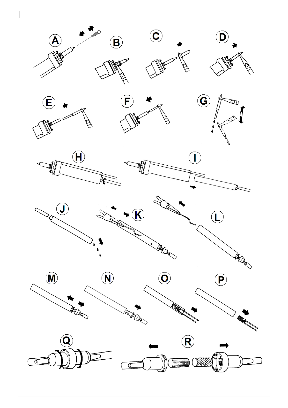
13. Cleaning procedure for clogged tips
CAUTION: BE VERY CAREFUL NOT TO BURN YOUR FINGERS WHEN CLEANING THE TIP.
Refer to the illustrations on page 3 of this manual.
1. Move the spring wire (included) back and forth [A] in order to clean the tip.
2. Raise the temperature of the heating element to allow the clogged solder to melt. Clean the tip by
sliding the spring wire up and down until the passage is clear (see [A])
3. Unscrew the barrel nut assembly ([B] & [C]).
4. Use a pair of pliers to remove the tip ([D] & [E]).
5. Reinsert the stainless tube in the heating element to melt the solder, as shown in [F]. This will take
approximately 5 seconds.
6. Remove the stainless tube and shake loose the molten solder [G]. The tip should now be unclogged;
Put the tip back in place and screw down the barrel nut assembly. Do not screw it down too tightly!
14. Procedure for Cleaning the Solder Collector
CAUTION: Put the main power switch in the "OFF"-position and allow the device to cool first.
Refer to the illustrations on page 3 of this manual.
1. Hold the soldering iron as shown in [H]. Press and turn the switch at the bottom of the iron.
2. Be careful not to burn your fingers on the glass solder collector as you slide it free (see [I]).
3. Point the collector downwards (see [J]) while shaking lightly to free the excess solder. Do this
frequently to keep the station in proper working order.
4. Remove the cooling strip with a pair of pliers ([K] & [L]).
5. Clean the cooling strip and the glass collector with a wire brush (included).
15. Replacement of Filters
Refer to the illustrations on pages 2 and 3 of this manual.
a. FILTER OF THE SOLDER COLLECTOR
1. Make sure that the iron and the filter have cooled sufficiently.
2. Point the soldering iron slightly upwards while pressing and turning the red switch on the butt of the
iron.
3. Remove the solder collector ([I]).
4. Disassemble the solder collector [M] & [N]).
5. Remove the old filter and replace it with a new one ([O] & [P]).
b. IN-LINE FILTERS
1. Unscrew the in-line filters and pull the two pieces apart ([Q]).
2. Replace the fillings of both filters as shown in [R].
c. FUME EXTRACTOR
1. Switch off the fume extractor and unplug it from the mains.
2. Replace the filter as shown in the illustrations on page 2.
Notes:
• Never attempt to wash filters with water, as this will reduce their effectiveness and increases risk
of damage to the pump.
• Dispose of used filters in accordance with local regulations.
08.02.2010 ©Velleman nv
9
Page 10
1
6
a
e
mdimwe
sev
oTh
e
.
aBeHe
atoe
h
.
h
p
r
v
m
f
t
t
m
n
n
e
gbat
erec
e
u
a
e
u
reen
agebver
tNeebes
eva
e
e
r
j
i
s
u
y
h
v
o
p
,
t
p
n
/d
u
b
i
s
r
e
c
u
b
n
d
m
o
o
e
t
s
e
h
B
o
e
e
w
R
e
e
p
a
tger
a
u
u
u
t
e
e
a
t
a
t
n
r
E
e
p
n
o
e
d
e
d
m
r
n
u
g
o
m
k
o
V
W
V
4
4
x
g
m
u
u
w
d
e
N
c
e
f
t
v
e
d
t
n
s
e
n
e
o
2
2
5
n
s
e
r
y
I
m
o
e
r
o
a
x
d
a
u
i
m
l
l
e
z
g
n
b
a
o
m
m
S
s
e
y
e
k
i
t
u
g
n
t
e
n
. Tec
m
ins power
h
ater
va
cuum pum
te
perature
ensions
ight
U
e this de
ent of da
F
r more in
e informa
©
COPYRIGHT
Th
e copyright
No
part of this
th
prior writte
nical sp
operating
ange
ice with o
age or in
o concern
ion in thi
NOTICE
o this man
anual or ma
consent of t
so
d
cificati
voltage
ldering
soldering
iginal acc
ury resul
ng this pr
manual i
al is owned
be copied, r
e copyright
ns
ssories o
ed from (i
oduct, ple
subject
by Vellema
produced, t
older.
VTSSD3
230
100
230
150300280
6.5k
nly. Velle
ncorrect)
se visit o
o change
nv. All worl
anslated or r
ac
/ 32Vac
ac mains p
80°C (30
50°C (57
190 x 13
an nv ca
se of thi
r websit
ithout pr
wide rights
duced to an
wer
-896°F)
-842°F)
mm
not be he
device.
www.vel
ior notice.
eserved.
electronic m
d respon
eman.eu.
dium or oth
ible in the
rwise withou
1
Inleidi
A
n alle ing
langrijke
bt u vrag
D
nk u voor
stel besch
In
oud:
2
Veiligh
1x
1x
1x
1x
1x
zetenen
milieu-inf
symbool o
Dit
geworpen
we
terijen) nie
ter
chtkomen
yclagepunt
n, contac
w aankoo
digd tijde
soldeersoldeerbo
desoldeer
dampafzu
reinigings
idsinst
d buiten h
Ho
GE
an de Eur
rmatie b
het toest
dit toestel
t bij het ge
voor recycl
brengen.
eer dan d
! Lees dez
s het trans
esoldeerst
t + punt e
out + pun
et
ucties
et bereik v
RUIK
pese Uni
treffende
l of de ver
schade ka
one huish
age. U mo
especteer
plaatseli
handleidin
ort, install
tion + voe
n houder
en houde
n kinderen
RSHA
dit produ
akking ge
toebrenge
udelijke a
t dit toeste
e plaatselij
jke autori
g grondig
er het dan
ingskabel
et puntrein
met puntr
en onbevo
DLEID
t
ft aan dat,
n aan het
val; het m
l naar uw v
ke milieuw
eiten bet
oor u het t
niet en ra
iger
iniger
egden.
NG
als het na
ilieu. Gooi
et bij een
erdeler of
tgeving.
effend de
estel in ge
dpleeg uw
ijn levensc
dit toestel
especialis
aar een lo
verwijder
ruik neem
dealer.
clus wordt
(en eventu
erd bedrijf
aal
ng.
. Werd het
le
Ve
mijd gebru
goed gev
Ra
k de scha
ruik de bo
keerd ge
On
koppel va
m de voe
chadigd zij
08
.02.2010
bruik dit t
G
n het circu
ik in de bu
ntileerde r
ht of de pu
t altijd ter
ruik onts
het lichtn
ingskabel
n. Laat uw
Ade
ens de pla
volg
estel nooit
it uit en on
de vrijge
rt van bra
imte.
nt van een
g in de ho
aat brand
t na gebrui
nkel bij de
dealer zo n
komen da
tselijke mil
op een ele
laad alle c
dbare pro
ingeschake
der en laa
evaar.
k of alvore
stekker va
dig een ni
pen nooit i
ieuwetgevi
tronisch ci
ndensator
10
ucten of e
lde (de)sol
afkoelen
s onderho
t. De voed
uwe kabel
n. Gooi da
g.
rcuit onder
n.
plosieve g
eerbout n
lvorens he
dswerkzaa
ngskabel
plaatsen.
pfilters en
spanning.
ssen. Gebr
oit aan. Pla
op te ber
mheden uit
ag niet om
soldeerresi
chakel eer
ik enkel in
ats na
en. Bij
te voeren.
geplooid of
u weg
st de voedi
©Vellema
g
nv
Page 11
3
.
a
.
e
e
e
z
c
S
D
u
I
d
e
W
E
u
g
R
d
t
v
d
r
c
v
h
/
a
o
s
d
f
s
d
s
-
o
®
e
e
n
n
n
’
g
N
g
R
e
G
s
D
k
E
a
u
h
E
j
e
a
o
k
a
e
p
u
m
j
u
t
o
t
e
u
e
e
s
t
e
e
r
d
k
a
s
n
o
D
s
u
l
u
A
u
i
o
p
n
b
b
j
m
i
r
e
m
m
S
S
7
n
a
e
n
g
a
z
I
a
N
h
a
h
N
e
n
A
a
r
n
s
t
r
e
e
.
b
Z
n
o
f
m
d
e
v
c
a
r
T
3
s
r
o
d
3
e
,
m
(
n
u
t
u
d
u
o
S
a
r
e
n
n
t
e
a
a
e
d
i
n
k
d
e
S
e
b
z
u
e
j
s
m
v
O
e
t
t
r
e
e
e
e
s
m
e
t
d
n
b
e
n
s
e
n
t
h
t
w
T
n
o
r
z
r
n
s
Algem
R
adpleeg de
ne richt
Velleman
lijnen
service-
n kwalite
VTSSD3
itsgaranti
achteraa
deze hand
leiding.
•
Leer eerst
•
Om veiligh
heeft aang
•
Gebruik h
De garanti
•
uw dealer
verband m
4
Eigens
•
STORING
geeft de di
verwarmin
VERGREN
•
temperatu
•
STROOMP
het geaar
•
UITSCHAK
nadat u d
•
LICHTGE
voor langd
•
ENERGIEB
temperatu
inschakelt,
by wordt h
Opmerkin
•
AFZONDE
afzonderlij
•
Geïsoleerd
zonder loo
•
Digitale ui
•
Stabiliteit
•
Bescherm
de nuldoo
•
Elektronis
niet te ver
•
Vacuümsc
thyristorsc
•
Soldeerafneemba
•
Pomp: de
•
Geïsoleerd
•
Storingsde
•
Energiebe
•
Standaard
•
Opties:
o reserve
o reserve
o reserve
o reserve
o reserve
o reserve
o huls vo
d
Gebrui
opspat
Besch
gerake
Besch
de functies
eidsredene
ebracht val
t toestel e
geldt niet
al de vera
ee houden.
happen
DETECTOR
splay ‘S--E
gselement
ELING VA
rsinstellin
EKVRIJ CI
e ontwerp
ELVERTRA
bediening
ICHT SOL
urig gebrui
SPAREND
r wordt d
zal de tem
et station
: Schakel
LIJKE INk of gelijkti
e voeding:
/desolder
lezing voor
an temper
tegen str
gangsscha
he temper
angen.
akelaar: d
hakelaar o
esoldeerbo
r voor ge
nafhankeli
e voeding:
tector voor
parende fu
desoldeerp
esoldeerp
ilter: FILT/
oldeerpun
esoldeerb
oldeerbou
ontstopve
r soldeerp
k het toest
tende vloei
rm tegen s
n
rm tegen s
van het to
mag u ge
t niet onde
kel waarvo
voor scha
twoordelij
VOOR HET
weer en z
eeft de di
DE TEMPE
via paswo
CUIT: Gee
n de nuld
ING VAN
knop heeft
EERBOUT:
.
FUNCTIE:
n automati
peratuur a
itgeschake
et station
N UITSCH
dig in- en
hoogwaard
n.
zowel de s
tuur: tem
ompieken:
eling.
tuurregeli
zuigfuncti
het handv
t: soldeer
akkelijk ge
ke vacuü
hoogwaard
het verwa
nctie.
unt (meeg
nten: 1,2
DES2
en: 0,2 m
ut: VTSSD
: VTSSC7/
r: VTSSD/
nt: VTSSC
l enkel bi
toffen. Pla
of en extr
chokken en
stel kenne
n wijzigin
de garanti
or het gem
e door het
heid afwij
VERWARM
l het verw
play ‘H--E’
RATUURSI
ord. Dit is
storing v
organgssc
E ZUIGFU
losgelaten.
Het kleine,
Het station
ch terugg
tomatisch
d.
it en opnie
KELING V
itschakelb
ge transfo
ldeerbout
eratuur va
geen stori
g: de temp
e wordt ge
at.
out (met k
ruik en on
pomp zorg
ge transfo
mingselem
leverd): BI
m (BITDE
(BITSSC1
3/DESOL
P3
P2
/SP4
nenshuis
ts geen o
me hitte.
vermijd br
voor u he
en aanbre
e.
akt is. Bij
negeren va
en voor de
NGSELEME
rmingsele
weer en za
STELLING:
andig aan
n gevoelig
akeling.
CTIE: De p
Zo wordt
ergonomis
schakelt n
bracht naa
aar de ing
uw in om h
N DE BOU
ar.
mator van
als de deso
n de punt i
g van ande
eratuur wo
tuurd door
lein, ergon
derhoud.
voor een
mator van
nt en de s
TDEST2 (1
ST2), 1,0
), 0,5 mm
Bescherm
jecten gev
org dat de
ute kracht
t gaat gebr
gen. Scha
noordeelk
n bepaalde
ecten of pr
NT EN DE
ent uitsch
l het verwa
Dit station
e montag
onderdele
omp zuigt
erstopping
he handva
20 minut
150°C. W
estelde wa
et toestel t
EN: De sol
2 VAC spe
ldeerbout.
nauwkeur
re toestelle
dt elektro
een gema
misch han
oorlopend
2 VAC.
nsor.
2 mm).
m (BITDE
BITSSC2)
tegen rege
ld met vlo
verluchting
ijdens de
iken.
e door wij
ndig gebr
richtlijnen
blemen di
ENSOR: Bi
kelen. Bij
mingsele
heeft een
lijn.
zoals CM
og ongeve
van de stif
wordt nie
n niet-geb
nneer u d
rde stijgen
resetten.
eer- en de
ciaal ontwo
g tot op ±
n dankzij h
isch gereg
kelijk te b
vat) en de
en onderh
T3), 1,5m
n, vochtigh
istof op he
sopeningen
ediening.
igingen die
ik vervalt
in deze ha
hier recht
storing va
toring van
ent uitscha
ergrendel
S-compon
r 1,5 seco
voorkome
warm en i
uik naar st
bout opni
. Na 40 mi
soldeerbou
rpen voor
3°C (6°F).
t geaarde
ld, u hoeft
dienen
oldeerbou
oudsvrije
(BITDES
id en
toestel.
niet verst
de gebruik
e garantie.
dleiding en
streeks
n de senso
het
kelen.
are
nten dank
den verde
n.
geschikt
and-by. De
uw
uten stand
zijn
et soldere
ontwerp en
de punt du
zijn
erking.
4)
pt
er
ij
-
08
.02.2010
11
©Vellema
nv
Page 12
VTSSD3
o huls voor desoldeerpunt: VTSSD3/SP2
o verwarmingselement voor desoldeerbout: VTSSD3/SP1
5. Omschrijving
Raadpleeg de figuren op pagina 2 van deze handleiding.
1 aan-uitschakelaar 7
▼
2 aansluiting soldeerbout 8 instelknop SET
3 aansluiting heteluchtslang 9 display
4 aansluiting desoldeerbout 10 temperatuuraanduiding
5 aansluiting vacuümpomp 11 temperatuureenheid (°C of °F)
▲
6
12 opwarmingsaanduiding
6. Beschrijving
Dit soldeer/desoldeerstation werd ontworpen met het oog op de huidige en toekomstige kwaliteitseisen
van de elektronica-industrie. De VTSSD3 voldoet dus ruimschoots aan de eisen van hobbyisten,
onderhoudspersoneel en productiepersoneel.
De VTSSD3 is uitgerust met een onafhankelijke, elektronisch gestuurde vacuümpomp. De pomp is
onderhoudsvrij. De pomp zal ook niet worden overbelast bij doorlopend gebruik. De vacuümpomp zorgt
voor een maximale zuigkracht van 50 cm/Hg en wordt geactiveerd door een drukknop op de behuizing.
De soldeerhouder in het handvat kan gemakkelijk worden verwijderd zodat u hem kunt schoonmaken. De
interne stollingsstrip zorgt voor een betere opvang van het soldeer in de glazen buis. De
ventilatieopeningen houden het handvat koel.
Dankzij het elektronische systeem van de VTSSD3 kunt u soldeertemperaturen instellen van 150 tot
480°C (302 tot 896°F) en desoldeertemperaturen van 300 tot 450°C (572 tot 842°F) waarbij u noch de
punt, noch het verwarmingselement hoeft te vervangen. De soldeerbout bevat een zeer goed geïsoleerd
keramisch verwarmingselement van Japanse makelij. De soldeerbout is uitgerust met een
precisiegewikkeld verwarmingselement. Een PTC-sensor (voor het keramische verwarmingselement van
de soldeerbout) en een thermokoppelsensor (voor het verwarmingselement van de desoldeerbout)
houden de temperatuur doorlopend op de normale werktemperatuur, met een maximale afwijking van
± 3°C (± 6°F). Het verwarmingselement warmt snel op en kan de temperatuur indien nodig snel
corrigeren dankzij de extra hoge maximale temperatuur. Het ergonomische ontwerp en het
siliconenrubberen handvat verhogen het comfort.
De revolutionaire ‘nuldoorgangsschakeling’ beschermt gevoelige componenten (CMOS-apparaten, enz.)
tegen de stroomstoten en spanningpieken die bij minder efficiënte, mechanisch geschakelde stations
dikwijls leiden tot beschadiging. De verwarmingselementen zijn galvanisch gescheiden van het net door
een scheidingstransformator die het systeem een veilige maximale spanning van 32 VAC laat gebruiken.
Zowel de soldeer- als de desoldeerbout zijn uitgerust met een temperatuurregelaar die zich op het
frontpaneel bevinden. Dankzij deze regelaars kan de gebruiker de temperatuur snel en nauwkeurig
regelen.
7. Werktemperatuur
SOLDEREN
De meest gebruikte soldeerlegeringen in de elektronica-industrie bestaan uit 60% tin en 40% lood.
Hieronder vindt u de werktemperatuur van dit type soldeer. Die temperatuur kan verschillen van fabrikant
tot fabrikant. De Europese RoHS-standaard verbiedt echter het gebruik en de verkoop van loodsoldeer.
Het toegelaten loodvrije soldeer smelt aan een temperatuur die gemiddeld 30°C (54°F) hoger ligt dan dat
van loodsoldeer.
loodsoldeer loodvrij soldeer
Smeltpunt 215°C (419°F) 220°C (428°F)
Normale werking 270-320°C (518-608°F) 300-360°C (572-680°F)
Productiedoeleinden 320-380°C (608-716°F) 360-410°C (680-770°F)
Een goede verbinding is verzekerd indien de werktemperatuur van de soldeerbout is afgestemd op de
werktemperatuur van het type soldeer dat u gebruikt. Het soldeer zal te traag vloeien bij een te lage
temperatuur; een te hoge temperatuur verbrandt de flux in het soldeer en veroorzaakt een hevige
rookontwikkeling. Dit leidt dan weer tot een droge verbinding of tot permanente beschadiging van de
printplaat.
08.02.2010 ©Velleman nv
12
Page 13
VTSSD3
DESOLDEREN
Hieronder vindt u de aanbevolen temperatuur voor de punt. Die temperatuur kan verschillen naargelang
van het type verbinding.
Voor een kleine verbinding: 320-360°C (of 608-680°F)
Voor een grotere verbinding: 370-400°C (of 698-752°F)
Bij een te lage temperatuur zal het soldeer te traag vloeien zodat de stift verstopt kan raken. Bij een te
hoge temperatuur kan de printplaat worden beschadigd.
8. Bedieningsinstructies
Raadpleeg de figuren op pagina 2 van deze handleiding.
Controleer of de werkspanning van het toestel identiek is aan die van de stroomvoorziening. Ga na of het
toestel niet werd beschadigd tijdens het transport.
ALGEMEEN
1. Plaats de voedingsschakelaar [1] op OFF.
2. Plug voorzichtig de soldeer- [2] en de desoldeerbout [4] in. Door de inkeping kunt u ze op slechts een
enkele manier aansluiten.
3. Verbind de vacuümleiding met de VAC-aansluiting[5].
4. Steek de voedingsstekker in het stopcontact.
DAMPAFZUIGER
Dit station wordt geleverd met een dampafzuiger. Gebruik hem bij elke soldeer- en desoldeertoepassing.
• Plaats of vervang de filter. Raadpleeg de figuur op pagina 2 van deze handleiding.
• Sluit de voedingskabel aan op dampafzuiger en steek daarna de voedingsstekker in het stopcontact.
• Plaats de dampafzuiger naast het station en schakel hem in.
INSTELLINGEN
• Schakel het station in [1].
• Houd SET [8] gedurende minstens 5 seconden ingedrukt tot ‘— — —’ op de display knippert. Geef het
paswoord (het standaard paswoord is ‘010’) in met ▲ [6] en druk op SET [8] om het instelmenu weer
te geven. Bij het invoeren van een ongeldig paswoord keert u terug naar de normale werkmodus
(temperatuuraanduiding).
• In het instelmenu zal de display ‘F-0’ weergeven. Selecteer de modus met ▲ [6] of ▼ [7]. Na 15
seconden keert het station terug naar de normale werkmodus.
• F-0: verlaten van het menu
Verlaat het instelmenu met SET [8]. U keert terug naar de temperatuurweergave.
• F-1: instellen van het paswoord
Wanneer de paswoordmodus ingeschakeld is, kan de gebruiker de temperatuursinstelling niet
wijzigen zonder eerst het paswoord ingevoerd te hebben.
Druk op SET [8] om het paswoordmenu weer te geven. Selecteer nu 000 (paswoord uitgeschakeld)
of 100 (paswoord ingeschakeld) met ▲ [6] of ▼ [7]. Druk opnieuw op SET [8] om naar het
instelmenu terug te keren.
• F-2: temperatuursinstelling
Druk op SET [8] om het instelmenu voor de temperatuur weer te geven. Geef de correctiemarge in
met ▲ [6] of ▼ [7]. Wanneer de weergegeven temperatuur afwijkt van de reële temperatuur van
de punt, kunt u de weergave hier ijken. Voorbeeld: weergegeven temperatuur = 300°C, reële
temperatuur van de punt = 290°C, voeg 10°C toe.
Een negatieve Celsiuswaarde wordt aangeduid met een minteken; een negatieve Fahrenheitwaarde
zal knipperen. Druk op SET [8] om naar het algemeen instelmenu terug te keren.
• F-3: stand-by/uitschakeling
Bij een ingeschakelde functie gaat het station na ongeveer 20 minuten rust in stand-by. Na
ongeveer 45 minuten rust wordt het station automatisch uitgeschakeld.
Opmerking: de functie is afzonderlijk instelbaar voor de soldeer- en de desoldeerbout.
Druk op SET [8] om het instelmenu weer te geven. Selecteer nu 000 (functie uitgeschakeld) of
100 (functie ingeschakeld) met ▲ [6] of ▼ [7]. Druk opnieuw op SET [8] om naar het instelmenu
terug te keren.
In stand-by daalt de temperatuur van de punt (naar 150°C (302°F) voor de soldeerbout en naar
200°C (392°F) voor de desoldeerbout) en knippert de displayweergave.
Opmerking: de functie is standaard uitgeschakeld.
U kunt de stand-bymodus op 3 manieren opheffen:
- neem de soldeerbout op of druk op de afzuigschakelaar van de desoldeerbout
- druk op een willekeurige knop
- schakel het station uit en opnieuw in [1]
08.02.2010 ©Velleman nv
13
Page 14

VTSSD3
In uitschakelmodus zal ‘— — —’ op de display knipperen. Druk op ▼ [7] om de bout opnieuw in te
schakelen.
• F-4: selecteren van de temperatuureenheid
U kunt een afzonderlijke temperatuur instellen voor zowel de soldeer- als voor de desoldeerbout.
Druk op SET [8] om het instelmenu weer te geven. Selecteer nu de eenheid (°C of °F ) met ▲ [6]
of ▼ [7]. Druk op SET [8] om naar het algemeen instelmenu terug te keren.
SOLDEREN/DESOLDEREN
BELANGRIJKE OPMERKING
Noch bij het solderen, noch bij het desolderen mag u temperaturen gebruiken die de 410°C (770°F)
overstijgen. U kunt het toestel wel kortstondig gebruiken bij hogere temperaturen, maar dan moet u
heel voorzichtig zijn.
OPGELET
Om brandwonden te vermijden mag u de metalen delen van de soldeer- en de desoldeerbout niet
aanraken tijdens gebruik of wanneer ze aan het afkoelen zijn.
1. Plaats de voedingsschakelaar op ON.
2. Druk op ▲ [6] onderaan de soldeerdisplay tot deze display de waarde 250°C weergeeft.
Opmerking: Houd ▲[6] of ▼ [7] ingedrukt om de waarde sneller te wijzigen. Tijdens het opwarmen
van de bout zal de opwarmingsaanduiding op de display [12] knipperen.
3. Vertin het oppervlak van de soldeerpunt en de desoldeerpunt door een nieuw beschermend laagje
soldeer aan te brengen.
4. Stel de gewenste temperatuur in.
Opmerking: de soldeer- en de desoldeerbout kunnen gelijktijdig worden gebruikt.
DESOLDEREN: BELANGRIJKE OPMERKINGEN
(a) U mag de vacuümpomp niet activeren vóór het soldeer volledig is gesmolten. Beweeg de stift rond de
uitloper tot het soldeer aan de bovenkant van de printplaat zichtbaar gesmolten is.
(b) Schakel de vacuümpomp uit wanneer de punt volledig vrij is van soldeer, anders kan de punt
verstopt raken.
(c) Voeg soldeer toe aan de verbinding om het desolderen te vereenvoudigen.
(d) Verwijder en reinig de soldeerhouder na maximaal 200 toepassingen. Niettemin raden wij u aan om
het toestel dagelijks te reinigen, zeker wanneer u het apparaat frequent gebruikt. Zie §13 & 14.
(e) Vervang de in-line filters en het katoenen kussentje in de soldeerhouder wanneer ze geel worden.
(f) In geval van onvoldoende zuigkracht moet u het meegeleverde reinigingsstiftje gebruiken om de
punt te reinigen. Controleer ook de in-line filters.
(g) Ga na of alle filters op hun plaats zitten tijdens de werking van het apparaat om beschadiging van de
vacuümpomp te vermijden.
(h) Lees ‘12. Onderhoud’ (zie verder) indien u de punt wilt vervangen.
9. Defecte punt: mogelijke oorzaken
• De temperatuur van de punt is hoger dan 410°C (770°F).
• De stiftpunt is onvoldoende vertind.
• De punt is in contact gekomen met een vuile of droge spons of met een oppervlak met een te hoog
zwavelgehalte.
• Contact met organische of chemische stoffen zoals plastic, hars, vetten en siliconen.
• Onzuiverheden in het soldeer en/of soldeer met een te laag tingehalte.
10. Tips voor het onderhoud van de punt
De soldeer- en de desoldeerbout maken gebruik van extreem hoge temperaturen. Schakel het toestel uit
wanneer u het wil reinigen.
Verwijder en reinig de punt na intensief gebruik. U moet de punt dagelijks reinigen indien u het toestel
frequent gebruikt. Verwijder overtollig soldeer in de stiftpunt om verstopping te vermijden.
De meegeleverde soldeer- en desoldeerpunten zijn vervaardigd uit koper bekleed met ijzer. Hun
levensduur blijft enkel behouden indien u ze gebruikt zoals het hoort.
• U moet de punt altijd vertinnen vóór u hem terug in de houder plaatst, vóór u het apparaat uitschakelt
of bij lange periodes van inactiviteit. Veeg de punt schoon met een natte spons vóór u begint of
gebruik onze reinigingsspons.
• De levensduur van de punt vermindert indien u te hoge temperaturen gebruikt (hoger dan 400°C of
750°F).
• Duw niet te hard op de punt tijdens het solderen/desolderen om beschadiging te vermijden.
• Gebruik geen vijlen of schurende materialen om de punt te reinigen.
• Gebruik geen vloeimiddelen die chloride of zuur bevatten. Gebruik enkel harshoudende vloeimiddelen.
• Verwijder eventuele oxidelaagjes door voorzichtig te polijsten met een amarildoek met korrel 600 –
800. U kunt ook isopropylalcohol gebruiken en vervolgens een nieuw laagje soldeer aanbrengen.
08.02.2010 ©Velleman nv
14
Page 15

VTSSD3
• Laat het toestel opwarmen tot 250°C (482°F) en stel na een drietal minuten de gewenste temperatuur
in. Het toestel is gebruiksklaar wanneer de ingestelde temperatuur wordt bereikt.
BELANGRIJK
Reinig de punt dagelijks. Verwijder overtollig soldeer van de stiftvergrendeling en de stiftpunt, anders kan
de punt samensmelten met het verwarmingselement of met de stiftvergrendeling.
11. Te lage zuigkracht: mogelijke oorzaken
Gebruik de procedure die hieronder wordt beschreven om uit te zoeken of het verlies van zuigkracht
wordt veroorzaakt door de punt, de soldeerhouder, de slang of de in-line filters.
OPGELET: PLAATS DE VOEDINGSSCHAKELAAR IN DE "OFF"-STAND OM HET TOESTEL TE LATEN
AFKOELEN VÓÓR U DEZE PROCEDURES TOEPAST.
a) Ontkoppel de vacuümslang van het frontpaneel. Plaats uw vinger op de opening van de aansluiting en
druk de vacuümschakelaar in. Nu beschikt u over een sterk vacuüm. Zo niet, dan moet u het apparaat
terugbrengen naar het verkooppunt om de pomp te laten herstellen.
b) Maak de in-line filters los van het handvat. Druk de vacuümschakelaar in en vervang de vulling van de
in-line filters indien er weinig of geen zuigkracht is of indien de filters verkleurd zijn.
c) Verwijder de soldeerhouder, plaats uw vinger op de opening en druk de vacuümschakelaar in. Reinig
of vervang de soldeerhouder indien het toestel over onvoldoende zuigkracht beschikt.
d) Druk de vacuümschakelaar in en reinig de stift met het meegeleverde reinigingsstiftje indien er geen
zuigkracht is. Lees "13. Reinigen van verstopte punten".
12. Onderhoud
Om de desoldeerpunt te vervangen hoeft u enkel de stiftvergrendeling los te schroeven. Schakel het
toestel eerst uit om het te laten afkoelen. Het toestel kan worden beschadigd indien het systeem is
ingeschakeld en de verwijderde punt niet werd vervangen.
Blaas het oxidestof in de stifthouder weg wanneer u de punt heeft verwijderd. Bescherm uw ogen tegen
dit stof. Vervang de punt en draai de schroef vast. U kunt een tang gebruiken om elk contact met hete
oppervlakken te vermijden. WEES ECHTER VOORZICHTIG: indien u de schroef te hard aanspant, kan het
verwarmingselement worden beschadigd of kunnen het element en de punt worden samengesmolten.
13. Reinigen van verstopte punten
OPGELET: VERBRAND UW VINGERS NIET TERWIJL U DE PUNT REINIGT.
Raadpleeg de figuren op pagina 3 van deze handleiding.
1. Beweeg het reinigingsstiftje heen en weer [A] om de zuigmond van de stift te reinigen.
2. Verhoog de temperatuur van het verwarmingselement om het gestolde soldeer te doen smelten.
Beweeg het reinigingsstiftje heen en weer tot de punt volledig vrij is (zie [A]).
3. Schroef de stiftvergrendeling los ([B] & [C]).
4. Verwijder de punt met een tang ([D] & [E]).
5. Stop de stift weer in het verwarmingselement om het soldeer te doen smelten (zie [F]). Dit duurt
ongeveer 5 seconden.
6. Verwijder de stift en schudt het gesmolten soldeer los [G]. De punt is nu vrijgemaakt. Breng de punt
terug op zijn plaats en schroef de stifthouder terug vast. Span de schroef niet te hard aan!
14. Reinigen van de soldeerhouder
OPGELET: Plaats de voedingsschakelaar op OFF en laat het toestel afkoelen voor u de soldeerhouder
reinigt.
Raadpleeg de figuren op pagina 3 van deze handleiding.
1. Houd de soldeerbout zoals afgebeeld in [H]. Druk de rode knop in die zich onderaan het handvat van
het soldeerijzer bevindt en draai de knop los.
2. Verbrand uw vingers niet wanneer u de glazen soldeerhouder verwijdert (zie [I]).
3. Richt de houder naar beneden (zie [J]) en schudt voorzichtig om het soldeer los te maken. Doe dit
geregeld om uw toestel gebruiksklaar te houden.
4. Verwijder de stollingsstrip met een tang ([K] & [L]).
5. Reinig de stollingsstrip en de glazen soldeerhouder met de meegeleverde staalborstel.
08.02.2010 ©Velleman nv
15
Page 16
1
5
aa.
2. Op
6
etemafm
e
e
eHe
.
uDeEn
o
v
v
R
r
o
b
d
r
d
N
e
A
e
e
d
h
e
g
b
t
w
o
R
v
e
e
u
t
uéve
p
y
n
u
m
v
n
d
r
e
e
v
s
o
d
w
s
o
e
k
b
e
m
o
r
u
e
a
u
l
n
o
e
r
e
d
)
M
e
a
D
k
d
k
e
t
c
n
n
e
a
m
e
d
.
d
r
z
e
a
i
g
C
o
s
c
é
c
é
p
a
d
d
o
O
R
ë
u
V
W
V
4
4
x
k
V
t
e
e
r
d
M
o
e
p
s
t
m
p
t
p
o
e
2
2
5
n
o
i
e
e
a
c
t
o
n
v
s
d
m
a
n
d
e
f
e
u
v
n
e
a
o
e
v
t
s
n
e
e
e
r
n
n
e
,
a
s
e
. Ver
R
adpleeg de
1.
De soldee
2.
Richt de s
de soldeer
Verwijder
3.
4.
Demontee
5.
Verwijder
b.
1.
Schroef de
2.
Vervang d
c.
1.
Schakel d
Vervang d
merkingen
• Spoel
• Gooi
1
. Tec
FILTE
IN-LI
DAMP
pomp
angen
figuren op
VAN DE S
bout en de
ldeerbout
out bevin
e soldeerh
de soldee
e oude filt
E FILTERS
in-line filt
vullingen
FZUIGER
dampafzui
filter zoal
:
een filter n
beschadig
ampfilters
nische
an filte
pagina’s 2
OLDEERHO
filter moet
aar boven
t en draai
ouder ([I]
houder ([
r en breng
rs los en tr
an de filte
ger uit en t
afgebeeld
oit af met
wordt.
eg volgen
pecific
s
en 3 van d
UDER
n voldoen
(zie fig. 8).
e knop los
.
] & [N]).
de nieuwe
k de twee
rs zoals afg
rek de voe
in de figuu
water: dit
s de plaats
ties
VTSSD3
ze handlei
e afgekoel
Druk de r
filter in ([
delen uitee
ebeeld in [
ingsstekke
op pagina
al de effici
lijke milie
ing.
zijn.
de knop in
] & [P]).
n ([Q]).
].
r uit het st
2.
ntie van d
wetgeving.
die zich on
pcontact.
filter ver
eraan het
inderen w
handvat va
ardoor de
vo
edingsspan
ve
rwarmings
w
rkspannin
peratuur
etingen
ge
wicht
G
bruik dit
sc
hade of k
pr
oduct, zie
g
wijzigd z
©
AUTEURS
V
lleman n
t is niet to
be
werken en
rechthebb
de
1
Introd
A
x résiden
s informa
cas de q
N
us vous re
l’a
ppareil. Si l
re
endeur.
ning
lement
vacuüm p
ereik
oestel en
etsuren
www.vell
nder voor
ECHT
heeft het
gestaan o
op te slaan
nde.
ction
s de l'Uni
tions envi
Ce
symbole s
pe
t polluer l'
ntuelles) p
l’a
pareil en q
rec
clage loca
l’e
vironneme
estions, c
ercions d
’appareil a
mp
so
lderen
d
solderen
el met ori
ij (verkee
man.eu.
afgaande
auteursre
deze han
op een ele
n europé
onnemen
r l'appareil
nvironnem
rmi les dé
estion. Re
. Il convie
t.
ntacter l
votre ach
été endom
ginele acc
rd) gebrui
e inform
ennisgev
cht voor d
leiding of
tronisch m
NOTI
nne
ales imp
ou l'emball
ent. Ne pa
hets muni
voyer les
t de respe
s autorit
t ! Lire la
agé pend
230
100
230
150300280
6,5
essoires.
k van dit
tie in dez
ng.
eze handl
edeelten e
edium zon
E D’E
rtantes c
age indiqu
jeter un a
ipaux non
quipemen
ter la régle
s locales
résente no
nt le trans
AC
/32 VAC
ac netspan
80°C (30
50°C (57
190 x 13
g
elleman
oestel. Vo
handleid
iding. All
van over t
er voorafg
PLOI
ncernant
que l’élimi
pareil élec
ujets au tr
s usagés à
entation l
our élimi
ice attenti
ort, ne pa
ning
-896°F)
-842°F)
mm
v is niet
r meer i
ng kan te
wereldwij
nemen, t
ande schri
e produit
nation d’un
rique ou él
i sélectif ;
votre fourn
cale relati
ation.
ement ava
l’installer
ansprakel
formatie
allen tijd
e rechten
kopiëren,
telijke toe
appareil e
ctronique
ne déchèt
isseur ou à
e à la prot
t la mise
t consulte
ijk voor
ver dit
worden
oorbehoud
e vertalen
temming v
fin de vie
et des pile
rie traitera
un service
ction de
n service d
votre
n.
te
n
de
08
.02.2010
16
©Vellema
nv
Page 17

C
o
.3.
e
S
T
m• N
L
e
.
gn
É
d
d
c
ccorend
el’a
v
a
s
f
n
u
é
r
t
O
p
A
p
U
ÉC
o
r
é
e
e
e
u
a
e
D
d
v
i
n
é
s
p
é
e
é
f
e
o
u
C
-
u
O
d
E
D
R
D
e
e
n
s
g
é
l
r
u
r
à
i
p
t
c
a
a
m
o
b
e
C
i
m
D
e
E
e
E
h
m
n'É
m
r
/
a
p
s
s
i
s
q
r
e
e
é
é
c
é
e
a
r
e
o
u
m
ÉR
é
f
S
A
n
m
u
a
p
n
d
i
s
b
e
e
e
d
s
m
e
a
t
e
e
h
É
a
S
x
A
t
e
n
m
m
a
r
p
g
d
l
n
e
e
e
t
n
P
o
h
s
o
e
n
s
E
c
D
c
s
n
n
t
o
.
e
s
s
é
n
ê
n
c
e
a
A
p
h
o
c
N
n
t
u
e
e
s
s
d
e
r
r
p
d
d
m
n
t
t
s
C
n
u
e
e
t
R
n
d
5
d
ntenu :
2
Consi
1x
1x
1x
1x
1x
station de
fer à soud
fer à dess
extracteu
ensemble
es de s
soudage/d
er + panne
uder + pa
de fumée
de nettoya
curité
ssoudage
et support
ne et sup
e
VTSSD3
vec cordo
avec laine
ort avec la
d’aliment
’acier pou
ne d’acier
tion
le nettoya
our le nett
ge
yage
Directi
S
référer à l
Ga
vi
en
Ne
à
in
Dé
N
rder hors d
ter l’usage
roit bien v
pas touch
essouder d
orrect pe
onnecter l
don d’alim
ommagé.
Ne j
sou
l’en
jamais ut
limentatio
es gén
garantie
Utili
des
Prot
fent
la portée
à proximit
ntilé.
r la tige ni
ans le supp
t engend
station d
ntation pa
emander
amais resp
ure en res
ironnemen
liser la sta
vers le cir
rales
de service
er cet app
rojections
ger contre
s de ventil
des enfant
de produit
a panne af
ort après u
er des ris
réseau ap
la fiche. L
votre rev
rer les fum
ectant la r
t.
ion sur un
uit et de d
et de qua
reil uniqu
d’eau. Ne j
la poussiè
tion ne soi
et des per
inflamma
n d’éviter t
age. Laiss
ues d’inc
ès usage o
câble d’ali
ndeur de r
es de sou
glementat
ircuit sous
charger le
lité Velle
ment à l'i
mais plac
e. Protéger
ent pas blo
onnes non
les ou de
out risque
r refroidir
ndie.
u avant tou
mentation
nouveler l
ure. Élimin
ion locale r
tension. Il
condensa
an® à la fi
ntérieur.
r d’objet c
contre la c
quées.
autorisées
az explosif
e brûlures.
e fer avant
t travail d’
e peut pa
câble d’ali
er les filtre
lative à la
st importa
eurs au pr
de cette
rotéger de
ntenant un
aleur extr
s. N’utiliser
Placer le f
le stockag
ntretien. M
être replis
mentation
et les rési
protection
nt de coup
alable.
otice.
la pluie, de
liquide sur
me. Veille
que dans
r à souder
. Un usag
anier le
é ou
i nécessair
us de
e
r
l’humidité
l’appareil.
à ce que l
n
ou
e.
et
s
•
e familiari
•
oute modi
odificatio
’utiliser q
•
a garantie
t votre rev
4
Caract
•
DISPOSITI
L’afficheur
du capteu
l’alimentat
DISPOSITI
•
fer à l’aide
de produc
•
PROTECTI
d’autres a
•
TEMPORIS
seconde a
•
FER A SO
prolongée.
•
MODE D'
de repos d
réactivant
Prot
er avec le
ication est
s par le cli
’à sa foncti
ne s’appliq
endeur déc
ristique
F DE DÉTE
affiche « S
. En cas d’
ion vers l’él
F DE VERR
d’un mot
ion.
N CONTR
pareils grâ
TION DE
rès que vo
DER LÉGE
En outre, l
ONOMIE
e 20 minut
le fer à sou
ger contre
onctionne
interdite p
nt ne tom
n prévue.
e pas aux
linera tout
s
TION EN
-E » et l’al
n dérègle
ément de c
UILLAGE
e passe. C
LES CRÊT
ce à la mis
ÉBRANCH
us avez lâc
: Les for
e manche
NERGIE :
s. En mê
de
dessou
les chocs
ent avant
ur des rais
ent pas so
Un usage i
dommages
responsab
AS DE D
mentation
ent de l’él
hauffe sera
E LA TEMP
ci est une
S DE TEN
à la terre
MENT DE L
é le bouto
es ergono
e se récha
La station
e temps, l
der la tem
t le traiter
l’emploi.
ns de sécu
s la garan
propre an
survenus
ilité pour le
ÈGLEMENT
vers l’élém
ment de c
coupée.
RATURE :
onction pr
ION ET LE
et la conne
POMPE :
. Ainsi tou
iques du f
ffe pas pe
passe auto
températu
érature re
vec circon
rité. Les d
ie.
ule d'offic
n négligea
problème
DE L’ÉLÉM
nt de chau
auffe, l’affi
Il est possi
tique pour
POINTES
ion « zero
La pompe
e obstructi
r à souder
dant l’utili
atiqueme
re de la pa
ontera au
pection pe
mmages o
la garanti
t certaines
et les déf
NT DE CH
ffe est cou
heur affic
ble de verr
toute appli
E COURA
cross ».
ontinue so
on de la pa
permetten
ation.
t en mode
ne est réd
omatiquem
dant l’opé
casionnés
.
directives
uts qui en
UFFE ET D
ée dès un
era « H--E
uiller la te
ation dans
: Pas d’i
opération
nne est évi
une utilisa
veille aprè
ite à 150°
ent à la val
ation.
ar des
e cette no
résultent.
CAPTEU
érègleme
» et
pérature
une chaîne
terférence
jusqu'à 1,
ée.
ion
une pério
. en
eur
ice
:
t
u
e
08
.02.2010
17
©Vellema
nv
Page 18

VTSSD3
sélectionnée. La station s’éteint après une période de repos de 40 minutes.
Remarque : Éteignez et puis rallumez la station pour réinitialiser les valeurs.
• UTILISATION SIMULTANÉE DES FERS : Les fers à souder et à dessouder peuvent être utilisés
simultanément et éteints séparément.
• Alimentation isolée : transformateur de 32 VCA haute qualité conçu pour le soudage sans
plomb/dessoudage.
• Affichage numérique pour le fer à souder comme pour le fer à dessouder.
• Stabilité de température : la température de la panne est réglée avec précision ±3°C (6°F).
• Protection contre les crêtes de tension et les pointes de courant : pas d'interférence d'autres appareils
grâce à la mise à la terre et la connexion « zero cross ».
• Réglage électronique de la température : température réglable sans remplacement de la panne.
• Commutateur à vide : la fonction aspiratoire est réglée par un thyristor à commande manuelle qui se
trouve sur la poignée pour des raisons pratiques.
• Fers : les fers à souder (poignée miniature ergonomique) et à dessouder sont faciles à utiliser,
démonter et remplacer.
• Pompe : pompe à vide indépendante assure l'opération en continu sans maintenance.
• Alimentation isolée : station alimentée par un transformateur de 24 VCA haute qualité.
• Dispositif de détection en cas de dérèglement de l’élément de chauffe et du capteur.
• Mode d’économie d’énergie.
• Panne standard (incluse) : BITDEST2 (1,2 mm).
• Options
o pannes de rechange (dessoudage) : 1,2 mm (BITDEST2), 1,0 mm (BITDEST3), 1,5 mm (BITDEST4)
o filtre de rechange : FILT/DES2
o pannes de rechange (soudage) : 0,2 mm (BITSSC1), 0,5 mm (BITSSC2)
o fer à dessouder de rechange : VTSSD3/DESOL
o fer à souder de rechange : VTSSC7/SP3
o ressort de nettoyage de rechange : VTSSD/SP2
o manchon pour panne de soudage : VTSSC7/SP4
o manchon pour panne de dessoudage : VTSSD3/SP2
o élément de chauffe pour fer à dessouder : VTSSD3/SP1
5. Description
Se référer aux illustrations à la page 2 de cette notice.
1 interrupteur marche/arrêt 7
bouton ▼
2 connexion du fer à souder 8 bouton SET
3 connexion de tuyau d’air chaud 9 afficheur
4 connexion du fer à dessouder 10 indication de la température
5 connexion de la pompe à vide 11 unité de température (°C ou °F)
bouton ▲
6
12 indication de réchauffement
6. Emploi
Cette station de soudage/dessoudage a été conçue afin de satisfaire aux exigences présentes et futures
du monde de l'électronique. La VTSSD3 convient donc parfaitement pour les hobbyistes comme pour les
services d'entretien et les ouvriers de production.
La VTSSD3 est équipée d'une pompe à vide indépendante et à pilotage électronique. La pompe assure
une opération sans entretien et elle ne sera pas surchargée en cas d'une opération continuelle. La pompe
à vide livre une force aspiratrice maximale (pression sous vide) de 50 cm/Hg et elle est activée au moyen
d'un bouton-poussoir qui se trouve sur le boîtier. Le réservoir de soudure se trouve dans la poignée et se
laisse facilement enlever lors du nettoyage. La tresse de refroidissement empêche une coulée trop vite de
la soudure et les fentes d'aération empêchent tout échauffement de la poignée.
La VTSSD3 est équipée d'une régulation électronique de la température de soudage entre 150 et 480°C
(302 à 896°F) et de la température de dessoudage entre 300 et 450°C (572 à 842°F) sans nécessiter un
remplacement de la panne ou de l'élément d'échauffement. Le fer à souder contient un élément
d'échauffement céramique bien isolé de fabrication japonaise. Le fer à dessouder est équipé d'un élément
d'échauffement bobiné à grande précision. Les variations de température sont réduites au minimum (±
3°C ou ± 6°F) grâce à un capteur PTC (pour l'élément d'échauffement du fer à souder) et un capteur
thermocouple (pour l'élément d'échauffement du fer à dessouder). L'élément d'échauffement chauffe
rapidement et la température est ajustée extrêmement vite grâce à la haute température maximale. Le
design ergonomique et la poignée de caoutchouc à la silicone augmentent le confort de l'utilisateur.
La connexion « zero cross » (quand le réseau passe par o) protège les composants sensibles (p.ex. les
appareils CMOS, etc.) contre les pointes de courant et les crêtes de tension qui, souvent, causent des
08.02.2010 ©Velleman nv
18
Page 19

VTSSD3
dégâts dans des stations commutées mécaniquement. Les éléments d'échauffement sont isolé
galvaniquement de la source d'alimentation par un transformateur de séparation qui permet au système
d'utiliser un maximum (sans risque) de 32 VCA. Les fers à souder et à dessouder sont équipés d'un
réglage de température qui se trouve sur le panneau frontal. Grâce à ce réglage, l'utilisateur peut ajuster
la température de façon rapide et efficace.
7. Température de travail
LE SOUDAGE
La plupart des alliages de soudure dans le monde de l'électronique sont des alliages 60/40 (étain 60% -
plomb 40%). Ci-dessous vous trouverez la température de travail de ce type de soudure, une
température qui varie selon le fabricant. Cependant, la vente et l’utilisation d’étain avec plomb est, par la
norme RoHS, interdite en Union européenne. L’étain sans plomb nécessitent une température plus élevée
de quelque 30°C (54°F).
étain avec plomb étain sans plomb
Point de fusion 215°C (419°F) 220°C (428°F)
Opération normale 270-320°C (518-608°F) 300-360°C (572-680°F)
Usage dans la production 320-380°C (608-716°F) 360-410°C (680-770°F)
Une bonne connexion est assurée si la température de travail du fer à souder correspond à la température
de travail du type de soudure employée. Une température trop basse amène une coulée trop lente : le flux
de la soudure risque de brûler en cas d'une température trop élevée, ce qui donne lieu à une fumée dense.
Cette fumée peut aboutir à une connexion sèche ou peut même occasionner un endommagement
permanent du circuit imprimé.
LE DESSOUDAGE
Ci-dessous vous trouverez la température recommandée pour la panne. Cette température varie selon le
type de connexion.
Pour une connexion de dimensions limitées : 320-360°C (ou 608-680°F)
Pour une connexion plus importante : 370-400°C (ou 698-752°F)
Une température trop basse causera la soudure à couler trop lentement, ce qui peut mener à une
obstruction de la panne. Une température trop élevée peut endommager le circuit imprimé.
8. Instructions d'opération
Se référer à l’illustration à la page 2 de cette notice.
Vérifiez si la tension de travail de l'appareil est identique à celle de l'alimentation en électricité. Vérifiez si
l'appareil n'a pas été endommagé pendant le transport.
EN GÉNÉRAL
• Mettez l'interrupteur d'alimentation [1] dans la position OFF.
• Branchez les fers à souder [2] et à dessouder [4]. Notez que les fiches de connexion ont un cran et
qu’elles ne peuvent être insérées que d’une seule façon dans la connexion.
• Branchez le tuyau à vide à la connexion VAC [5].
• Connectez le câble d'alimentation CA au réseau.
EXTRACTEUR DE FUMÉES
Cette station est livrée avec un extracteur de fumées. Utilisez-le à chaque application de soudage été de
dessoudage.
• Installez ou remplacez le filtre. Référez-vous à l’illustration en page 2.
• Connectez le câble d’alimentation à l’arrière de l’extracteur et insérez la fiche dans une prise de
courant.
• Placez l’extracteur près de la station et allumez-le.
PARAMÉTRAGE
• Allumez la station [1]
• Maintenez enfoncé le bouton SET [8] pendant au moins 5 secondes jusqu’à ce que « — — — » clignote
sur l’afficheur. Entrez le mot de passe (010 par défaut) avec le bouton ▲ [6] et renfoncez le bouton
SET [8] pour accéder au menu. Vous reviendrez au mode d’utilisation (affichage de la température)
lors de la saisie d’un mot de passe invalide.
• Une fois accédé au menu, l’afficheur affichera « F-0 ». Enfoncez le bouton ▲ [6] ou ▼ [7] pour
sélectionner le mode. La station revient au mode d’utilisation après une période de repos de 15
secondes.
08.02.2010 ©Velleman nv
19
Page 20

VTSSD3
• F-0 : quitter le menu
Enfoncez le bouton SET [8] lorsque l’afficheur affiche F-0 quitter le menu et revenir à l’affichage de
la température.
• F-1 : le mot de passe
Une fois le mot de passe activé, vous ne pourrez plus modifier la température de la panne.
Enfoncez le bouton SET [8] pour accéder au menu. Sélectionnez 000 (mot de passe désactivé) ou
100 (mot de passe activé) avec le bouton ▲ [6] ou ▼ [7]. Renfoncez le bouton SET [8] pour
revenir au menu principal.
• F-2 : instauration de la température
Enfoncez le bouton SET [8] pour accéder au menu. Entrez la valeur corrective avec le bouton
▲ [6] ou ▼ [7]. Cette fonction permet détalonner l’afficheur lorsque la température affichée ne
correspond pas avec la température réelle de la panne. Exemple : température affichée = 300°C,
température réelle : 290°C, ajouter 10°C.
Une température °C négative est indiquée par un signe moins devant la valeur ; une température
°F négative clignotera. Renfoncez le bouton SET [8] pour revenir au menu principal.
• F-3 : mode veille/extinction automatique
Cette fonction met la station en veille après une période de repos de 20 minutes. Après environ 45
minutes, la station s’éteint automatiquement.
Remarque : il est possible d’activer la fonction séparément pour les fers à souder et à dessouder.
Enfoncez le bouton SET [8] pour accéder au menu. Sélectionnez 000 (fonction désactivée) ou 100
(fonction activée) avec le bouton ▲ [6] ou ▼ [7]. Renfoncez le bouton SET [8] pour revenir au
menu principal.
En mode veille, la température de la panne à souder est réduite à 150°C (302°F), celle de la panne
à dessouder à 200°C (392°F). L’afficheur clignote.
Remarque : cette fonction est désactivée par défaut.
Pour quitter la fonction :
- prenez le fer à souder en main ou enfoncez le bouton d’extraction des fumées sur le fer à
dessouder, ou
- enfoncez un bouton lorsque l’afficheur clignote, ou
- éteignez la station et rallumez-la [1].
En mode d’extinction automatique, « — — — » clignote sur l’afficheur. Enfoncez le bouton ▼ [7]
pour réactiver le fer.
•
F-4 : unité de température
Les températures des deux fers peuvent être instaurées séparément.
Enfoncez le bouton SET [8] pour accéder au menu. Sélectionnez l’unité de température (°C ou °F)
avec le bouton ▲ [6] ou ▼ [7]. Renfoncez le bouton SET [8] pour revenir au menu principal.
SOUDAGE ET DE DESSOUDAGE
REMARQUES IMPORTANTES
Évitez des températures supérieures à 410°C (770°F) lors du soudage/dessoudage. L'appareil se laisse
néanmoins utiliser à des températures plus élevées pendants des intervalles de courte durée. AGISSEZ
AVEC CIRCONSPECTION DANS CE CAS.
ATTENTION
Évitez les brûlures: ne touchez pas les parties métalliques du fer à souder et du fer à dessouder lors de
l'usage ou lorsqu'ils sont en train de refroidir.
1. Placez l'interrupteur d'alimentation [1] en position OFF.
2. Enfoncez le bouton ▲ [6] sous l’afficheur gauche jusqu’à ce qu’il affiche 250°C.
Remarque : Maintenez enfoncé le bouton ▲ [6] ou ▼ [7] pour modifier la température plus
rapidement. L’indication de réchauffement [12] clignote sur l’afficheur clignote lorsque la panne se
réchauffe.
3. Étamez la surface de la panne de soudage et de la panne de dessoudage en appliquant une nouvelle
couche protectrice de soudure.
4. Sélectionnez la température pour chaque fer.
Remarque : les fers à souder et à dessouder se laissent utiliser simultanément.
LE DESSOUDAGE : REMARQUES IMPORTANTES
(a) La pompe à vide ne peut pas être activée avant que la soudure soit complètement fondue. Faites
fondre la soudure en touchant la panne aux bords des extrémités jusqu'à ce que la soudure en
dessus du circuit imprimé soit visiblement fondue.
(b) Débranchez la pompe à vide dès que tout résidu de soudure à été enlevé, sinon la panne peut
devenir obstruée.
(c) Ajoutez de la soudure à la connexion afin de faciliter le dessoudage.
(d) Enlevez et nettoyez le réservoir de soudure après maximum de 200 applications. Néanmoins, nous
vous conseillons de nettoyer l'appareil fréquemment, surtout lors d’une utilisation au quotidien.
Référez-vous aux chapitres §13 et 14.
08.02.2010 ©Velleman nv
20
Page 21

VTSSD3
(e) Remplacez les filtres in-line et les coussinets en coton du réservoir de soudure quand ils
commencent à jaunir.
(f) S'il n'y a pas assez de force aspiratrice, vous devez nettoyez la panne avec le nettoyeur de panne
inclus. Contrôlez les filtres in-line régulièrement.
(g) Vérifiez si tous les filtres sont à leur place pendant l'opération de l'appareil afin d'éviter tout
endommagement de la pompe à vide.
(h) Lisez « 12. Entretien » pour l'installation d'une nouvelle panne.
9. Panne défectueuse : causes possibles
• La température de la panne dépasse 410°C (770°F)
• La panne n'est pas suffisamment étamée.
• La panne est entré en contact avec une éponge sèche ou sale ou avec une surface trop sulfureuse.
• Du contact avec des matières organiques ou chimiques comme le plastique, la résine, les graisses et
les silicones.
• Des impuretés dans la soudure et/ou de la soudure avec une teneur d'étain trop basse.
10. Entretien de la panne
Les fers à souder et à dessouder utilisent des températures très élevées. Débranchez l'appareil avant de
le nettoyer.
Enlevez et nettoyez la panne après chaque usage intensif. Nettoyez la panne chaque jour en cas d'une
utilisation fréquente. Enlevez la soudure superflue afin d'éviter toute obstruction de la panne.
Les pannes incluses sont faites en cuivre avec une couche de fer. Leur durée de vie reste optimale en cas
d'une utilisation appropriée.
• N'oubliez pas d'étamer la panne avant de la replacer dans son support, avant de débrancher l'appareil
ou lors d'une longue période d'inactivité. Avant de commencer, vous devez nettoyer la panne à l'aide
d'une éponge mouillée ou de notre nettoyant.
• La durée de vie de la panne sera raccourcie si vous employez des températures excessives (qui
dépassent donc 400°C ou 750°F).
• N'appuyez pas trop fort sur la panne pendant le (des)soudage pour éviter tout endommagement.
• Évitez l'usage de limes et de matières abrasives lors du nettoyage de la panne.
• Évitez l'usage de fondants acidifères ou de fondants qui contiennent de la chlorure. N'utilisez que des
fondants résineux.
• Enlevez des couches d'oxyde en polissant prudemment avec du papier d'émeri avec un grain de 600 à
800. Vous pouvez également utiliser de l'alcool iso propyle et appliquer par la suite une nouvelle
couche protectrice de soudure.
• Vous pouvez instaurer la température désirée trois minutes après que l'appareil à atteint une
température de 250°C (482°F). La station de soudage/dessoudage est prêt à l'emploi dès que la
température instaurée est atteinte.
IMPORTANT
Nettoyez la panne journellement. Enlevez toute soudure superflue de la panne et du dispositif de
verrouillage. Sinon, vous risquez de faire fondre soit la panne et l'élément d'échauffement, soit la panne
et son dispositif de verrouillage.
11. Force aspiratrice insuffisante: causes possibles
Utilisez la procédure élaborée ci-dessous afin de déterminer la cause de la perte de force aspiratrice : la
panne, le réservoir de soudure, le tube ou le filtre in-line.
ATTENTION : N'OUBLIEZ PAS DE PLACER L'INTERRUPTEUR D'ALIMENTATION EN POSITION « OFF »
AVANT DE COMMENCER AFIN QUE L'APPAREIL PUISSE REFROIDIR.
a) Déconnectez le tube à vide du panneau frontal. Couvrez le trou de la douille de votre doigt et pressez
le commutateur à vide, ce qui crée un vide adéquat. Vous devez ramener l'appareil au point de vente
en cas de problèmes avec la pompe.
b) Détachez les filtres in-line de la manche. Pressez le commutateur à vide et remplacez le remplissage
des filtres in-line dans le cas d'une absence (quasi) totale de force aspiratrice ou si les filtres ont jauni.
c) Enlevez le réservoir de soudure, couvrez le trou de votre doigt et pressez le commutateur à vide.
Nettoyez ou remplacez le tube du réservoir si la force aspiratrice est insuffisante.
d) Dans le cas d'une absence totale de force aspiratrice: pressez le commutateur à vide et nettoyez la panne au
moyen du nettoyeur de panne inclus. Lisez « 13. Nettoyage de pannes obstruées ».
12. Entretien
La panne de soudage est facile à remplacer : vous n'avez qu'à dévisser le dispositif de verrouillage.
Débranchez d'abord l'appareil afin de garantir un refroidissement adéquat avant de remplacer la panne.
Vous risquez d'endommager l'appareil s'il reste branché sans que la panne soit remplacée.
08.02.2010 ©Velleman nv
21
Page 22

VTSSD3
Une fois la panne enlevée, vous devez souffler la poussière du support de la panne. N'oubliez pas de
protéger vos yeux ! Remplacez la panne et serrez la vis au moyen d'une pince afin d'éviter tout contact
avec des surfaces chaudes. ATTENTION : si la vis est trop serrée, vous risquez d'endommager l'élément
ou de faire fondre l'élément et la panne.
13. Nettoyage de pannes obstruées
ATTENTION : FAITES ATTENTION À NE PAS BRÛLER VOS DOIGTS EN NETTOYANT LA PANNE.
Se référer aux illustrations à la page 3 de cette notice.
1. Employez le nettoyeur de panne afin de nettoyer le bec de la panne [A].
2. Augmentez la température de l'élément d'échauffement pour permettre à la soudure coagulée de
fondre. Débloquez la panne avec le nettoyeur de panne (voir [A]).
3. Dévissez le dispositif de verrouillage (fig. [B] & [C]).
4. Enlevez la panne avec une pince (fig. [D] & [E]).
5. Réintroduisez la panne dans l'élément d'échauffement afin de fondre la soudure coagulée (voir [F]), ce
qui prendra environ 5 secondes.
6. Enlevez la panne et détachez la soudure fondue en secouant [G]: la panne est maintenant débloquée.
Replacez la panne et visser le dispositif de verrouillage. Faites attention de ne pas serrer la vis trop
fort !
14. Nettoyage du réservoir de soudure
ATTENTION : Débranchez l'appareil et attendez à ce qu'il soit refroidi avant de nettoyer le réservoir de
soudure.
Se référer aux illustrations à la page 3 de cette notice.
1. Tenez le fer à souder comme montré dans la fig. [H]. Pressez et dévissez le bouton rouge en bas de la
manche du fer à souder.
2. Faites attention à ne pas brûler vos doigts en enlevant le réservoir de soudure (voir [I]).
3. Dirigez le réservoir vers le sol (voir [J]) et secouez prudemment afin de dégager la soudure. Répétez
cette action fréquemment afin de garder votre VTSSD3 dans un état d'opération parfait.
4. Enlevez la tresse de refroidissement avec une pince (fig. [K] & [L]).
5. Nettoyez la tresse de refroidissement et le réservoir de soudure avec la brosse métallique incluse.
15. Remplacement des filtres
Se référer aux illustrations à la page 2 et 3 de cette notice.
a. LE FILTRE DU RESERVOIR DE SOUDURE
1. Le fer à souder et le filtre doivent être suffisamment refroidis.
2. Dirigez le fer à souder vers le ciel (voir fig. 8). Pressez le et dévissez le bouton rouge en bas de la
manche du fer à souder.
3. Enlevez le réservoir de soudure ([I]).
4. Démontez le réservoir de soudure ([M] & [N]).
5. Enlevez l'ancien filtre et insérez le nouveau ([O] & [P]).
b. FILTRES IN-LINE
1. Dévissez les filtres in-line et séparez les deux parties ([Q]).
2. Remplacez les remplissages des filtres comme montré dans la fig. [R].
c. EXTRACTEUR DE FUMÉES
1. Éteignez l’extracteur et débranchez-le du réseau électrique.
2. Remplacez le filtre comme illustré en page 2.
Remarque :
• Ne jamais laver les filtres avec de l’eau. Un lavage du filtre réduira l’efficacité de celui-ci et
augmentera le risque d’endommagement de la station.
• Éliminer les filtres en respectant la réglementation locale relative à la protection de
l’environnement.
08.02.2010 ©Velleman nv
22
Page 23

1
6
é
mdim
uinf
A
snopré
.
mSi
rSi dis
c
.
c
h
p
c
m
s
D
n
e
t
u
a
s
e
m
b
a
a
h
c
o
o
d
ede
i
n
d
e
e
a
n
n
c
i
n
b
t
a
+
d
a
o
v
e
p
r
p
i
s
e
e
s
c
o
M
r
a
e
d
a
S
e
a
o
y
i
o
c
a
r
c
o
v
a
L
o
b
e
p
e
t
p
u
l
o
h
u
a
b
n
V
W
V
4
4
x
k
r
ê
u
n
u
U
e
a
n
e
p
e
b
a
r
o
a
a
e
a
u
n
z
a
r
2
2
5
V
c
b
o
e
e
u
c
a
g
g
o
p
a
n
e
l
n
d
e
d
e
t
n
m
o
n
v
a
e
i
.
p
a
n
r
n
d
n
a
b
a
t
o
e
ó
n
s
T
e
r
n
n
s
e
e
e
a
. Spé
ali
mentation
él
ment de c
ali
mentation
te
pérature
ensions
po
ids
employer
N’
sponsable
re
s d’infor
pl
ormation
©
DROITS
S
Vellema
ré
ervés. Tou
tice par qu
alable écri
ificatio
auffe
ompe à vi
so
d
et appar
de domm
ation co
présenté
’AUTEUR
est l’aya
te reprodu
lque procé
de l’ayant
s techn
e
udage
ssoudage
il qu’avec
ges ou lé
cernant c
es dans c
t droit de
tion, tradu
dé ou sur t
droit.
ques
des acces
ions surv
t article,
tte notice
droits d’
tion, copie
ut support
VTSSD3
230
100
230
150300280
6,5
soires d’o
enus à un
isitez not
peuvent
uteur po
ou diffusio
électroniq
CA
/32 VCA
CA
80°C (30
50°C (57
190 x 13
g
igine. SA
usage (in
re site we
tre modifi
r cette no
, intégrale
e que se s
-896°F)
-842°F)
mm
elleman
orrect) d
www.ve
ées sans
tice. Tous
ou partiell
it est inter
e sera au
cet appa
leman.eu.
otificatio
roits mon
, du conte
ite sans l’
cunement
eil. Pour
Toutes le
préalabl
iaux
u de cette
ccord
.
1
Introd
A
los ciudad
portante
I
tiene dud
G
acias por h
el aparato
tribuidor.
In
luye:
2
1x
1x
1x
1x
1x
Instru
cción
nos de la
informac
Est
símbolo e
dañ
ar el medio
do
éstica; de
dist
ribuidor o a
iente.
am
s, contac
ber compr
a sufrido
estación d
soldador
desoldado
accesorio
juego de l
ciones
M
antenga el
Unión Eu
ones sobr
este apar
ambiente.
e ir a una
la unidad
e con las
ado la VTS
lgún daño
e soldadur
punta y s
r + punta
para la asp
impieza
e segur
aparato lej
ANUA
opea
e el medi
to o el em
No tire est
mpresa es
e reciclaje
utoridad
D3! Lea a
n el trans
/desoldad
porte con
soporte c
ración de
idad
s del alcan
DEL
ambient
alaje indic
aparato (
ecializada
local. Resp
s locales
entament
orte no lo i
ra con ca
impiador p
n limpiado
umos
ce de pers
SUARI
concerni
que, si tir
i las pilas,
en reciclaj
te las leye
ara resid
las instruc
nstale y pó
le de alime
ra puntas
para punt
nas no cap
O
nte a est
a las mues
si las hubie
. Devuelva
s locales e
os.
iones del
ngase en c
ntación
s
acitadas y
producto
ras inservi
ra) en la b
este apara
relación c
anual ant
ntacto con
iños.
les, podría
sura
o a su
n el medio
s de usarla
su
n
.
utilice el
N
lu
gar airead
toque el
N
(
e)soldador
macenarlo.
al
sconecte
D
l enchufe
al
imentación
S
es necesa
08
.02.2010
parato cer
.
ástago ni l
en el sopo
Un uso in
l aparato d
ara descon
y protéjalo
io, pida a s
ca respire l
Nun
etar la regl
res
a de prod
punta par
te después
orrecto p
e la red elé
ectar el ca
contra pos
u distribuid
s humos d
amentació
ctos inflam
evitar cu
del uso. D
uede caus
ctrica desp
le de red,
ibles daños
or reempla
e soldadur
local con
23
bles o de
lquier ries
je que el s
r peligro
és del uso
unca del p
causados
ar el cable
. Tire los fi
especto a l
as explosi
o de quem
ldador se
de incend
o antes de
ropio cable
or algún ti
de aliment
ltros y los r
protecció
o. Utilice s
duras. Po
nfríe ante
o.
limpiarlo.
No aplast
o de supe
ción.
esiduos de
del ambie
lo en un
ga el
de
ire siempr
el cable d
ficie afilada
soldadura
te.
©Vellema
.
l
nv
Page 24

.
é
.
u
s
a
p
o
o
s
b
e
R
e
v
a
Ó
p
(
T
R
A
e
e
ó
L
s
ó
ó
m
c
o
o
ó
e
d
d
s
e
p
r
t
u
d
a
n
d
e
D
e
n
E
n
A
c
D
L
E
o
d
v
p
a
p
s
o
r
a
e
n
s
d
r
o
a
s
e
n
o
a
p
a
N
y
d
M
p
T
ñ
b
a
u
:
o
e
v
A
d
a
n
ó
n
a
i
a
m
S
o
e
e
g
s
a
r
s
,
d
c
g
N
o
A
r
N
a
ó
a
n
a
t
s
s
o
a
a
e
o
m
a
n
D
m
m
VTSSD3
i
o
c
c
e
L
e
o
e
o
n
d
o
a
c
t
i
t
n
u
n
n
d
e
m
S
)
i
e
e
é
p
e
A
l
d
E
s
e
n
m
e
d
r
r
e
a
d
o
m
B
o
m
d
e
n
a
a
t
R
e
T
é
r
a
o
s
d
s
z
e
d
n
T
t
s
á
S
d
d
i
e
A
(
0
m
m
e
m
r
n
s
a
a
u
r
i
3
Norma
V
ase la Gar
•
Familiaríce
•
Por razone
causados
Utilice sól
•
garantía c
•
Daños cau
y su distri
4
Caract
•
DETECTO
visualiza «
correctam
se desacti
BLOQUEO
•
contraseñ
PROTECCI
•
de otros a
de cero »
•
SUCCIÓN
botón. De
•
SOLDADO
mango no
•
MODO DE
después d
reactivar e
estación s
Observaci
•
USO SIMU
posible de
•
alimentaci
•
visualizaci
•
estabilidad
•
protección
completa
•
ajuste ele
•
conmutad
operación
•
soldador /
uso y repa
•
bomba : b
•
alimentaci
•
aparato d
•
modo de a
•
punta está
•
opción
o puntas
o filtro de
o puntas
o desolda
N
ci
nca utilice
rcuito y de
genera
ntía de s
Utilice
ningún
No ex
Asegú
No agi
se con el f
s de seguri
or modific
el aparato
mpletame
ados por
uidor no s
rísticas
EN CASO
S--E » en l
nte. Si el
a el eleme
DEL AJUST
. Esto es u
N CONTR
aratos gra
zero cross)
EMPORIZA
esta maner
LIGERO:
se calienta
HORRO D
20 minut
l soldador/
desactiva
n: Desacti
TÁNEO DE
activarlos
n aislada :
n digital t
de la tem
contra las
ente puest
trónico de l
r al vacío :
desoldado
ración
mba de v
n aislada :
detección
horro de e
ndar de de
e desolda
recambio:
e soldadu
dor de reca
el aparato
cargue tod
les
rvicio y c
el aparato
tipo de sal
onga este
ese de que
e el aparat
ncionamie
ad, las m
ciones no
para las a
te.
escuido de
rá respons
E MAL FU
a pantalla
lemento ca
to calenta
DE LA TE
a función
LAS CRES
ias al dise
.
A: La bom
a se evita l
as formas
durante el
ENERGÍA
s. Al mism
esoldador
después d
e y luego
LOS SOLD
or separa
transform
nto para el
eratura : p
obrecorrie
a tierra y
a temperat
la aspiraci
: soldador
cío indepe
transform
n caso de
ergía
oldadura (
ura de rec
FILT/DES2
a de reca
mbio: VTS
si el circuit
s los cond
lidad Vell
ólo en int
picadura o
quipo a po
los orificio
o. Evite us
to del apa
dificacione
utorizadas
licaciones
las instruc
ble de nin
CIONAMIE
se desacti
lentador n
or.
PERATUR
ráctica pa
AS DE TE
o complet
a continúa
obstrucci
ergonómic
so.
La estació
tiempo, l
la tempera
40 minuto
uelva a act
DORES: E
o.
dor 32VAC
soldador c
recisión de
tes : no h
la conmut
ura : temp
n se contr
(con mini
diente par
dor 24Vac
mal funcio
ncl.) : BIT
mbio: 1.2
bio: 0.2m
D3/DESOL
está bajo
nsadores.
man ® al f
eriores. N
oteo.
lvo. No exp
de ventila
r excesiva
ato antes d
no autoriz
no están
escritas en
iones de s
ún daño u
TO DEL E
va el elem
funciona c
: Es posibl
a cualquier
SIÓN Y LO
mente pue
trabajand
n de la pu
s del solda
pasa aut
temperatu
ura subirá
.
ivar la esta
posible u
de alta cal
mo para el
la tempera
y interfere
ción de ten
ratura reg
la por un t
ango ergo
un funcio
de alta cali
amiento d
EST2 (1.2
m (BITDE
(BITSSC1
tensión. Pr
nal de este
exponga
onga este
ión no est
fuerza dura
e utilizarlo.
adas del a
ubiertos po
este manu
guridad de
otros probl
EMENTO C
nto calenta
rrectamen
bloquear
aplicación
S PICOS D
sto a tierra
hasta 1.5
ta.
or permit
máticamen
ra de la pu
utomática
ión para r
ilizar los so
dad diseña
desoldado
ura de la p
cias de ot
sión "cruce
lable sin n
iristor, situ
ómico) y
amiento c
ad
l elemento
m)
T2), 1.0m
, 0.5mm (
mero desc
manual de
ste equipo
quipo a te
n bloquea
nte el man
arato está
r la garantí
al. Su uso i
este manu
mas resul
LENTADO
dor si el se
te, aparece
a temperat
e una cad
CORRIEN
y la conmu
eg. despu
n un uso p
te al modo
ta se dism
ente al v
inicializar l
ldadores y
a para sol
unta hasta
os aparato
de cero" (
cesidad d
do en el m
esoldador
ntinuo y si
calentador
(BITDES
ITSSC2)
necte la ali
l usuario.
a lluvia, hu
peraturas
os.
jo y la ins
prohibida
a.
ncorrecto a
l invalidar
antes.
Y EL SEN
nsor no fun
« H--E » e
ura del sol
na de pro
E: no hay
tación de t
s de haber
olongado.
de espera
inuye a 15
lor seleccio
s valores.
imultánea
ar sin plo
±3°C
gracias al
ero cross)
cambiar la
ango lo qu
esmontabl
manteni
y el senso
3) 1.5mm
mentación
medad ni a
extremas.
alación.
. Los daño
nula la
n su garan
OR: Se
ciona
n la pantall
ador con u
ucción.
nterferenci
nsión « cr
soltado el
demás, el
standby)
°C. al
nado. La
ente y es
o/desolda
diseño
punta
facilita la
es para fác
iento
(BITDEST4
del
tía
y
na
s
ce
l
)
08
.02.2010
24
©Vellema
nv
Page 25

VTSSD3
o soldador de recambio: VTSSC7/SP3
o baqueta de recambio para la limpieza: VTSSD/SP2
o funda para punta de soldadura: VTSSC7/SP4
o funda para punta de desoldadura: VTSSD3/SP2
o elemento calentador para desoldador: VTSSD3/SP1
5. Características
Véase las figuras en la página 2 de este manual del usuario.
1 interruptor ON/OFF 7
botón ▼
2 conexión del soldador 8 botón SET
3 conexión del tubo de aire caliente 9 pantalla
4 conexión del desoldador 10 indicador de la temperatura
5 conexión de la bomba de vacío 11 unidad de temperatura (°C o °F)
botón ▲
6
12 indicación de recalentamiento
6. Descripción
Esta estación de soldadura/desoldadura ha sido diseñada para cumplir con los requisitos presentes y
futuros del mundo de la electrónica. La VTSSD3 resulta idónea no sólo para los aficionados sino también
para los servicios de mantenimiento y la producción.
La VTSSD3 está equipada con una bomba de vacío independiente y control electrónico. La bomba
asegura una operación libre de mantenimiento y no se sobrecarga en caso de un funcionamiento
continuo. La bomba de vacío suministra una succión máx. de 50cm/Hg y se activa con el pulsador
incorporado en la caja. El depósito de soldadura incorporado en el mango se quita fácilmente para la
limpieza. La trenza de enfriamiento evita que el estaño corra demasiado rápido. Las ranuras de
ventilación impiden un calentamiento del mango.
La VTSSD3 está equipada con una regulación electrónica de la temperatura de soldadura entre 150 y
480°C (de 302 a 896°F) y la temperatura de desoldadura entre 300 y 450°C (de 572 a 842°F) sin
necesidad de cambiar la punta o el elemento calentador. El soldador tiene un elemento calentador
cerámico aislado de fabricación japonesa. El soldador está equipado con un elemento calentador bobinado
de alta precisión. Las variaciones de temperatura se reducen al mínimo (± 3°C o ± 6°F) gracias a un
sensor PTC (para el elemento calentador cerámico del soldador) y un sensor termopar (para el elemento
calentador del desoldador). El elemento calentador se calienta rápidamente y la temperatura se ajusta
muy rápidamente gracias a la temperatura elevada máxima. El diseño ergonómico y el mango de goma
con siliconas aumentan el confort para el usuario.
La conexión "cruce de cero" (si la red pasa por cero) protege los componentes sensibles (por ejemplo los
aparatos CMOS, etc.) contra los picos de corriente y las crestas de tensión que causan normalmente
daños en las estaciones conmutadas mecánicamente. Los elementos calentador están aislados
galvánicamente de la fuente de alimentación por un transformador de separación que permite al sistema
usar un máximo (sin riesgo) de 32VCA. Los soldadores y desoldadores están equipados con un ajuste de
temperatura que está en el panel frontal. Gracias a este ajuste, el usuario puede ajustar la temperatura
de manera fácil y eficaz.
7. Temperatura de funcionamiento
LA SOLDADURA
La mayoría de las aleaciones de soldadura en el mundo de la electrónica son aleaciones "60/40" (estaño
60% - plomo 40%). Véase abajo para la temperatura de trabajo de este tipo de soldadura, una
temperatura que varia según el fabricante. Sin embargo, la norma RoHS prohíbe la venta y el uso de
estaño con plomo en la Unión Europea. El estaño sin plomo necesita una temperatura más elevada de
unos 30°C (54°F).
estaño con plomo estaño sin plomo
Punta de fusión 215°C (419°F) 220°C (428°F)
Funcionamiento normal 270-320°C (518-608°F) 300-360°C (572-680°F)
Uso en la producción 320-380°C (608-716°F) 360-410°C (680-770°F)
Se asegura una buena soldadura si la temperatura de trabajo del soldador corresponde con la temperatura
de trabajo del tipo de estaño usado. Tenga en cuenta que una temperatura demasiada baja causa un flux
demasiado lento: a temperaturas muy elevadas, el flux del estaño se quema, lo que da lugar a un humo
denso. Este humo puede tener como resultado una soldadura seca o puede dañar permanentemente el
circuito impreso.
08.02.2010 ©Velleman nv
25
Page 26

VTSSD3
LA DESOLDADURA
Véase abajo la temperatura recomendada de la punta. Esta temperatura varía según el tipo de conexión.
Para una conexión de dimensiones limitadas : 320-360°C (608-680°F)
Para una conexión más importante : 370-400°C (698-752°F)
A temperaturas demasiado bajas, el estaño correrá demasiado lente, lo que puede obstruir la punta.
Temperaturas demasiado elevadas pueden dañar el circuito impreso.
8. Instrucciones de funcionamiento
Véase la figura en la página 2 de este manual del usuario.
Verifique si la tensión eléctrica es la adecuada para el aparato. Verifique si el aparato no ha sido dañado
durante el transporte.
GENERAL
1. Ponga el interruptor de alimentación [1] en la posición "OFF".
2. Conecte el soldador [2] y el desoldador [4] A causa de la muesca sólo puede conectarlos de una sola
manera.
3. Conecte el tubo de vacío a la conexión VCA [5].
4. Conecte el cable de alimentación CA a la red.
ACCESORIO PARA LA ASPIRACIÓN DE HUMOS
Esta estación está equipada con un accesorio para la aspiración de humos. Utilícelo para cada aplicación
de soldadura y desoldadura.
• Instale o reemplace el filtro. Véase la figura en la página 2.
• Conecte el cable de alimentación a la parte trasera e introduzca el conector en un enchufe.
• Ponga el aparato cerca de la estación y actívelo.
AJUSTES
• Active la estación [1]
• Mantenga pulsado el botón SET [8] durante al menos 5 segundos hasta que « — — — » parpadee en
la pantalla. Introduzca la contraseña (010 por defecto) con el botón ▲ [6] y vuelva a pulsar el botón
SET [8] para entrar en el menú. Volverá al modo de funcionamiento (visualización de la temperatura)
al introducir una contraseña inválida.
• Después de haber entrado en el menú, la pantalla visualiza « F-0 ». Pulse el botón ▲ [6] o ▼ [7] para
seleccionar el modo. La estación vuelve al modo de funcionamiento después de 15 segundos.
• F-0 : salir del menú
Pulse el botón SET [8] si la pantalla visualiza F-0 para salir del menú y volver a la visualización de
la temperatura.
• F-1 : la contraseña
Después de haber activado la contraseña, ya no puede modificar la temperatura de la punta.
Pulse el botón SET [8] para entrar en el menú. Seleccione 000 (contraseña desactivada) o 100
(contraseña activada) con el botón ▲ [6] o ▼ [7]. Vuelva a pulsar el botón SET [8] para volver al
menú principal.
• F-2 : ajustar la temperatura
Pulse el botón SET [8] para entrar en el menú. Introduzca el valor de corrección con el botón ▲ [6]
o ▼ [7]. Esta función permite calibrar la pantalla si la temperatura visualizada no coincide con la
temperatura real de la punta. Ejemplo: temperatura visualizada = 300°C, temperatura real: 290°C,
añadir 10°C.
Una temperatura °C negativa está indicada por signo negativo delante del valor; una temperatura
°F negativa parpadeará. Vuelva a pulsar el botón SET [8] para volver al menú principal.
• F-3 : modo de espera/desactivación automática
Esta función pone la estación en el modo de espera (standby) después de 20 minutos. Después de
aproximadamente 45 minutos, la estación se desactiva automáticamente.
Observación: Es posible ajustar esta función por separado tanto para el soldador como para el
desoldador.
Pulse el botón SET [8] para entrar en el menú. Seleccione 000 (función desactivada) o 100
(función activada) con el botón ▲ [6] o ▼ [7]. Vuelva a pulsar el botón SET [8] para volver al
menú principal.
En el modo de espera, la temperatura de la punta de soldadura baja a 150°C (302°F), la
temperatura de la punta de desoldadura baja a 200°C (392°F). La pantalla parpadea.
Observación: esta función está desactivada por defecto.
Para salir la función:
- ponga el soldador en la mano o pulse el botón para extraer humo del desoldador
- pulse cualquier botón
08.02.2010 ©Velleman nv
26
Page 27

VTSSD3
- desactive la estación y vuelva a activarla [1].
En el modo de desactivación automática, « — — — » parpadea en la pantalla. Pulse el botón ▼ [7]
para volver a activar el soldador.
• F-4 : unidad de temperatura
Es posible ajustar la temperatura de dos soldadores por separado.
Pulse el botón SET [8] para entrar en el menú. Seleccione la unidad de temperatura (°C o °F) con
el botón ▲ [6] o ▼ [7]. Vuelva a pulsar el botón SET [8] para volver al menú principal.
SOLDADURA Y DESOLDADURA
OBSERVACIONES IMPORTANTES
Evite temperaturas superiores a 410°C (770°F) al soldar/desoldar. No obstante, puede usar el aparato
a temperaturas muy elevadas durante períodos cortos. EN ESTE CASO: SEA EXTREMADAMENTE
CUIDADOSO.
¡OJO!
Evite quemaduras: no toque las partes metálicas del soldador ni del desoldador durante el uso o la
refrigeración.
1. Ponga el interruptor de alimentación en la posición "ON".
2. Pulse el botón ▲ [6] en la parte inferior izquierda de la pantalla hasta que visualiza 250°C.
Observación: Mantenga pulsado el botón ▲ [6] o ▼ [7] para modificar la temperatura de manera más
rápida. La indicación de recalentamiento [12] parpadea si la punta se recalienta.
3. Aplique una nueva capa de protección de estaño en la superficie de la punta del soldador y la punta del
desoldador.
4. Seleccione la temperatura para cada soldador.
Observación: se puede usar el soldador y el desoldador simultáneamente.
LA DESOLDADURA: OBSERVACIONES IMPORTANTES
(a) No active la bomba de vacío hasta que el estaño se haya fundido completamente. Para ello, toque
con la punta del desoldador el estaño hasta que se haya fundido visiblemente en la parte superior del
circuito impreso.
(b) Desconecte la bomba de vacío si todos los residuos de estaño han sido eliminados, si no, se puede
obstruir la punta.
(c) Añada estaño a la soldadura para facilitar la desoldadura.
(d) Quite y limpie el depósito de estaño después de 200 aplicaciones máximo. No obstante, aconsejamos
limpiar el aparato frecuentemente, sobre todo, si se usa todos los días. Véase §13&14.
(e) Cambie los filtros in-line y los cojinetes de algodón del dispositivo de estaño si comienzan a
amarillear.
(f) Si no hay suficiente succión, limpie la punta con el limpiador de punta (incluido). Controle los filtros
in-line frecuentemente.
(g) Verifique si todos los filtros están en su lugar durante el funcionamiento para no dañar la bomba de
vacío.
(h) Lea "12. Mantenimiento" para el cambio de la punta.
9. Punta defectuosa: causas posibles
• La temperatura de la punta sobrepasa 410°C (770°F)
• La punta no tiene suficiente estaño
• La punta ha tocado una esponja seca o sucia o una superficie demasiado sulfúrica.
• El contacto con materias orgánicas o químicas como el plástico, la resina, las grasas y las siliconas.
• Impurezas en la soldadura y/o soldadura con insuficientemente estaño.
10. Mantenimiento de la punta
El soldador y el desoldador alcanzan temperaturas muy elevadas. Desconecte el aparato antes de
limpiarlo.
Quite y limpie la punta después de cada uso intensivo. Limpie la punta cada día en caso de uso frecuente.
Quite la soldadura superflua para evitar la obstrucción de la punta.
Las puntas incluidas son de cobre con una capa de hierro. Usándolas correctamente, aumentará su larga
duración.
• No se olvide de estañar la punta antes de colocarla en el soporte, antes de desactivar el dispositivo o
durante un largo periodo de inactividad. Antes de empezar, limpie la punta con una esponja húmeda o
con nuestro limpiador.
• Se disminuye la duración de vida de la punta al utilizar temperaturas excesivas (más de 400°C o
750°F).
• No apoye excesivamente la punta durante la (de)soldadura para evitar daños.
• Nunca limpie la punta con una lima o materiales abrasivos.
• Nunca use flux conteniendo cloruro o ácido. Sólo use fluxes que contienen resina.
08.02.2010 ©Velleman nv
27
Page 28

VTSSD3
• Si se ha formado una película de óxido, quítela cuidadosamente puliéndola con papel de lija con un
grano de 600 a 800. Puede usar también alcohol isopropilo al aplicar después una nueva capa de
protección de soldadura.
• Ponga la temperatura deseada 3 minutos después de que el aparato haya alcanzado una temperatura
de 250°C (482°F). La estación de soldadura/desoldadura está lista para usar después de haber
alcanzado la temperatura deseada.
IMPORTANTE
Limpie la punta diariamente. Elimine todo exceso de soldadura de la punta y del dispositivo de
bloqueo. Si no, se arriesga a que se funda, bien la punta y el elemento calentador, bien la punta y el
dispositivo de bloqueo.
11. Succión insuficiente: causas posibles
Use el procedimiento resumido abajo para determinar la causa de la pérdida de fuerza de succión: la
punta, el depósito de soldadura, el tubo o el filtro in-line.
¡OJO!: NO SE OLVIDE DE PONER EL INTERRUPTOR DE ALIMENTACIÓN EN LA POSICIÓN "OFF"
ANTES DE EMPEZAR. DE ESA MANERA, EL DISPOSITIVO SE PUEDE ENFRIAR.
a) Desconecte el tubo de vacío del panel frontal. Cubra el hueco con su dedo y pulse el conmutador de
vacío, lo que crea un vacío adecuado. Si no es el caso: devuelva el aparato al punto de venta para
reparar la bomba.
b) Desconecte los filtros in-line del mango. Pulse el conmutador de vacío y reemplace el llenado de los
filtros in-line si (casi) no hay succión o si los filtros han amarilleado.
c) Quite el depósito de soldadura, cubra el hueco con su dedo y pulse el conmutador de vacío. Limpie o
reemplace el tubo del depósito si la succión es insuficiente.
d) Si no hay succión: pulse el conmutador de vacío y limpie la punta con un limpiador de puntas incluido. Lea
"13. Limpiar puntas obstruidas".
12. Mantenimiento
Es fácil de cambiar la punta: desatornille sólo el dispositivo de bloqueo. Ante todo, desconecte el aparato
para garantizar un enfriamiento adecuado antes de reemplazar la punta. Es posible dañar la estación de
soldadura al dejarla activada sin reemplazar la punta.
Una vez extraída la punta, elimine el polvo del soporte de la punta. ¡Proteja sus ojos! Introduzca la nueva
punta y apriete el tornillo con una pinza para evitar todo contacto con las superficies calientes. ¡OJO!:
Puede dañar el elemento o puede hacer fundir el elemento y la punta al apretar demasiado el tornillo.
13. Limpiar puntas obstruidas
¡OJO!: TENGA CUIDADO CON NO QUEMARSE LOS DEDOS AL LIMPIAR LA PUNTA.
Véase las figuras en la página 3 de este manual del usuario.
1. Utilice el limpiador de puntas para la limpieza [A].
2. Aumente la temperatura del elemento calentador para que el estaño pueda fundir. Saque la punta con
el limpiador de punta (véase figura [A]).
3. Desatornille el dispositivo de bloqueo (véase figura [B] & [C]).
4. Extraiga la punta con una pinza (véase figura [D] & [E]).
5. Introduzca la punta en el elemento calentador para hacer fundir la soldadura (véase figura [F]). Esto
durará aproximadamente 5 segundos.
6. Extraiga la punta y quite la soldadura fundida sacudiéndola [G]. La punta está liberada. Cambie la
punta y atornille el dispositivo de bloqueo. ¡No lo atornille demasiado fuerte!
14. Limpiar el depósito de soldadura
¡OJO!: Ponga el interruptor en la posición “OFF” y deje que se enfríe el aparato.
Véase las figuras en la página 3 de este manual del usuario.
1. Mantenga el soldador como se muestra en la figura [H]. Pulse y desatornille el botón rojo debajo del
mango del soldador.
2. Sea muy cuidadoso con no quemarse los dedos al quitar el deposito de soldadura (véase figura [I]).
3. Apunte el depósito hacia el sol (véase figura [J]) y muévalo cuidadosamente para liberar la soldadura.
Repita esta acción frecuentemente para mantener la VTSSD3 en buen estado.
4. Quite la trenza de enfriamiento con una pinza (figura [K] & [L]).
5. Limpie la trenza de enfriamiento y el depósito de soldadura con el cepillo metálico incluido.
08.02.2010 ©Velleman nv
28
Page 29

1
5
éa.
2. Ob
6
etentemdim
tdaeses
emu
a
.
n
a
m
u
T
s
e
t
O
e
S
e
e
n
e
e
e
a
a
i
t
o
S
V
s
s
r
w
m
s
d
h
w
r
o
l
n
c
p
T
E
d
o
o
R
y
é
t
a
a
o
b
e
ó
s
o
O
d
s
r
m
h
v
B
r
ü
o
E
y
i
e
e
e
r
u
l
a
u
g
d
e
m
E
ü
r
e
n
ü
s
e
S
V
m
U
a
r
g
s
e
D
d
2
n
s
d
.
u
p
U
s
r
e
H
e
i
)
&
g
e
S
l
V
W
V
4
4
x
g
e
e
r
e
d
r
N
c
l
l
r
e
u
e
o
e
c
2
2
5
a
e
o
c
e
N
z
m
e
o
n
u
t
n
t
e
m
f
a
n
e
n
d
g
n
b
m
a
n
m
a
n
e
o
e
e
t
n
b
o
. Ree
V
ase las fig
1.
Asegúrese
2.
Apunte el
mango del
3.
Quite el d
4.
Desmonte
5.
Quite el fil
b.
1.
Desatornill
2.
Reemplac
c.
1.
Desactive
Reemplac
servacio
• Nunca
• Saqu
1
. Esp
EL FIL
FILTR
ACCE
riesgo
plazar
ras en las
RO DEL D
de que el
oldador ha
soldador.
pósito de s
el depósito
ro viejo e i
S IN-LINE
e los filtros
los llenad
ORIO PA
l aparato
el filtro (v
es:
lave los fil
de dañar l
los filtros
cificaci
los filtr
áginas 2 y
POSITO D
esoldador
cia el cielo
ldadura (f
de soldadu
ntroduzca
in-line y s
s de los filt
A LA ASP
desconéct
ase la figu
ros con ag
estación.
l respetar
nes
s
3 de este
SOLDAD
el filtro h
(véase figu
gura [I]).
ra (figuras
l nuevo (fi
pare amba
ros como s
IRACIÓN
lo de la re
a en la p.
a. Al lavar
a reglame
VTSSD3
anual del
RA
n sido enfr
a 8). Aprié
[M] & [N]
uras [O]
partes (fi
muestra
E HUMO
eléctrica.
).
el filtro se
tación loca
usuario.
ados.
telo y dest
.
[P]).
ura [Q]).
n la figura
disminuye
con respe
rnille el bo
[R].
l rendimie
to a la pro
ón rojo de
to y se au
ección del
ajo del
enta el
mbiente.
ali
mentación
el
mento cal
sión de tr
peratura
ensiones
pe
so
U
ilice este
ños ni les
te produc
pecificaci
©
DERECHO
V
lleman N
ndiales re
m
nual del u
1
Einfüh
A
alle Ein
W
ichtige U
F
lls Zweife
Wi
r bedanke
so
rgfältig dur
ntador
bajo de la
parato s
ones cau
o, visite n
nes y el c
DE AUT
dispone
ervados. E
uario o pa
ung
ohner der
weltinfor
Die
es Symbol
Pro
uktes nac
Ein
eit (oder
ver
endeten
we
den. Diese
ret
urniert we
bestehen
uns für de
h. Überpr
omba al v
so
ldar
d
soldar
lo con los
ados por
uestra pá
ntenido
R
e los der
tá estricta
tes de ello
Europäisc
ationen
auf dem P
seinem L
erwendete
atterien m
Einheit mu
den. Resp
, wenden
n Kauf der
fen Sie, ob
B
cío
accesorio
n uso (in
ina www
e este ma
chos de a
ente proh
sin previo
DIEN
hen Union
ber diese
odukt ode
benszyklus
Batterien)
ssen von
s an den
ktieren Sie
ie sich fü
TSSD3! L
Transports
230
100
230
150300280
6.5k
originale
ebido) d
velleman.
nual sin p
tor para
ibido repro
ermiso esc
NGSA
Produkt
der Verpa
der Umwe
nicht als u
iner spezia
ändler ode
die örtlich
r Entsorg
sen Sie di
chäden vor
ac
/ 32Vac
ac
80°C (30
50°C (57
190 x 13
. Vellem
este apar
u. Se pu
evio avis
ste manu
ucir, tradu
ito del der
LEITU
kung zeigt
t Schaden
nsortiertes
isierten Fir
ein örtlich
n Umweltv
ngsrichtli
se Bedien
liegen.
-896°F)
-842°F)
mm
n NV no s
ato. Para
den modi
.
al del usu
ir, copiar,
cho habie
G
an, dass di
ufügen ka
Hausmüll;
a zwecks
s Recyclin
rschriften.
ien an Ih
ngsanleitu
rá respo
ás infor
icar las
rio. Todos
editar y gu
te.
Entsorgu
n. Entsorg
ie Einheit
Recycling
-Unterneh
re örtlich
g vor Inbe
sable de
ación so
los derech
rdar este
g dieses
n Sie die
der
ntsorgt
men
Behörde.
riebnahme
re
s
08
.02.2010
29
©Vellema
nv
Page 30

Li
e
.3.
e
.
:
h
a
aGe
eSieh
rNedaBe
ezu
e
i
h
h
n
h
e
n
c
S
-
L
u
O
g
L
d
W
P
e
/
t
a
s
w
a
g
o
a
d
a
z
g
S
r
h
n
t
i
e
t
d
u
e
P
r
E
s
T
g
S
D
s
K
N
n
e
n
n
t
h
G
f
b
f
h
e
D
ä
u
z
G
s
t
c
r
c
s
E
h
U
w
e
s
e
a
m
r
o
e
n
d
m
n
n
e
r
r
S
n
d
a
g
s
B
R
k
k
L
K
r
e
d
i
n
i
e
e
g
d
E
n
e
t
n
d
h
n
c
e
D
h
s
h
G
P
r
S
c
ä
B
R
e
K
m
e
S
i
s
e
n
s
e
S
v
M
k
g
e
o
1
s
E
h
n
c
d
g
n
s
e
T
ä
n
u
w
s
R
i
r
e
m
z
e
e
h
a
S
r
ä
T
g
s
n
s
e
e
e
t
0
t
n
n
e
B
ß
e
e
n
d
n
m
ferumfang
2
Sicher
1x
1x
1x
1x
1x
H
Löt-
Entlö
Lötkolben
Entlötkolb
Lötdampf
Reinigung
eitshin
lten Sie Ki
Station +
+ Spitze u
en + Spitz
bsaugung
satz
eise
nder und U
etzkabel
d Halter
und Halte
befugte v
VTSSD3
it Spizenre
mit Spize
m Gerät fe
niger
reiniger
rn.
Allgem
Si
he Vellem
H
B
T
V
lten Sie d
rät nur in
rühren Sie
e den Lötk
e Sie ihn l
ennen Sie
tzstecker
ss die Net
schädigun
Atm
den
rwenden
erst die St
ine Ric
an® Servi
Verwe
und Fe
aus.
Schütz
Beach
s Gerät vo
ut gelüfte
nie die Sc
lben nach
gern. Bei
as Gerät
n der Griff
leitung nic
en soll ein
en Sie die
örtlichen U
ie das Ger
omversorg
tlinien
ce- und Q
den Sie da
uchte. Set
en Sie das
en Sie, das
brennbar
en Räume
acht oder
ebrauch i
alscher A
ei Nichtben
läche an u
t gequetsc
Fachkraft
ämpfe nie
mweltvorsc
t nie wenn
ung des Kr
alitätsga
s Gerät nu
en Sie das
erät vor
s die Lüftu
n Produkte
.
ie Spitze e
mer wied
wendung
utzung und
d ziehen S
ht oder dur
das Kabel
ein. Entsor
hriften.
der elektro
ises ab un
antie am
im Inne
Gerät kein
taub. Schü
gsschlitze
n oder expl
nes einges
r in den St
entsteht
vor jeder
ie nie an d
ch scharfe
rsetzen.
en Sie Da
nische unt
entladen
nde dieser
bereich. S
r Flüssigke
zen Sie da
icht blocki
osivem Ga
halteten (
nder und l
randgefa
einigung v
r Netzleitu
anten bes
pffilter un
r Spannun
ie alle Ko
Bedienung
chützen Si
t wie z.B.
Gerät vor
rt werden.
. Verwend
nt)Lötkolb
assen Sie i
r.
om Netz. F
g. Achten
hädigt we
d Lötrückst
steht. Sch
densatoren
anleitung.
das Gerät
ropf- oder
extremen
n Sie das
ns. Stecke
n abkühle
ssen Sie d
ie darauf,
den kann.
nde gemä
alten Sie
.
vor Regen
Spritzwass
emperatur
n
n
ei
r,
n.
•
Nehmen S
haben.
•
Eigenmäc
eigenmäc
•
Verwende
dies zu Sc
•
Bei Schäd
Garantiea
4
Eigens
•
STÖRUNG
Display ‘SDisplay ‘H
VERRIEGE
•
Temperat
•
SCHUTZ V
des völlig
•
AUSSCHA
Sie die Be
•
LEICHTGE
längere An
•
ENERGIES
nicht verw
Verme
und B
e das Gerä
tige Verän
tige Änder
Sie das G
äden am
n, die durc
spruch. Fü
haften
MELDER B
-E’ an und
-E’ an und
UNG DER
reinstellun
R STROM
eerdeten
TVERZÖGE
ienungsta
ICHT LÖT
wendung.
ARFUNKTI
ndet wird.
den Sie Er
dienung de
erst in Be
erungen si
ngen erlis
rät nur für
rodukt füh
h Nichtbea
daraus re
I DEFEKT
chaltet sic
schaltet sic
EMPERAT
über Pass
PITZEN: k
esigns.
RUNG DER
te losgelas
OLBEN: D
ON: Die St
Die Tempe
chütterung
s Gerätes.
rieb, nach
nd aus Sich
ht der Gar
Anwendun
en und erli
htung der
ultierende
M HEIZKÖ
das Heiz
h das Heiz
RSEINSTE
ort. Dies i
ine Störun
SAUGFUN
en haben.
r kleine, e
tion schalt
ratur wird
en. Vermei
em Sie sic
erheitsgrü
ntieanspru
en beschri
cht der Ga
edienungs
Folgeschäd
PER UND
örper absc
örper ab.
LUNG: Die
st praktisc
g anderer
TION: Die
So wird Ve
gonomisch
t auf den
ann autom
en Sie roh
mit seine
den verbot
h.
eben in die
rantieanspr
anleitung v
n übernim
EN SENSO
alten. Bei
e Station
in einem
eräte dan
umpe sau
stopfung d
e Griff wird
tandby-M
atisch auf
e Gewalt w
Funktione
en. Bei Sch
er Bedien
uch.
rursacht
mt der Her
: Bei Stör
töring des
erfügt übe
ontageban
der Nulldu
t noch ung
r Spitze v
nicht war
dus um we
50°C redu
hrend der
n vertraut
äden verur
ngsanleitu
erden, erli
teller kein
ng des Sen
Heizkörper
eine verri
d.
rchgangsve
efähr 1.5 S
rmieden.
und eigne
nn diese 2
iert. Schal
Installation
emacht
acht durch
g sonst ka
cht der
Haftung.
sors zeigt
s zeigt das
gelbare
rbindung u
k. nachde
sich für
Minuten
en Sie den
n
as
d
08
.02.2010
30
©Vellema
nv
Page 31

VTSSD3
Lötkolben wieder ein, so steigt die Temperatur automatisch auf den eingestellten Wert. Nach 40
Minuten im Standby-Modus wird die Station ausgeschaltet.
Bemerkung: Schalten Sie die Station aus und wieder ein, um das Gerät rückzusetzen.
• SEPARATE EIN- UND ABSCHALTUNG DER LÖTKOLBEN: Der Löt- und Entlötkolben können separat oder
gleichzeitig ein- und ausgeschaltet werden.
• isolierte Stromversorgung: hochwertiger Transformator von 32VAC speziell entworfen zum bleifreien
Löten/entlöten
• Digitalanzeige für sowohl Löt- als auch Entlötkolben
• Stabilität der Temperatur: Genauigkeit der Spitzentemperatur bis ±3°C
• Schutz vor Stromspitzen: keine Störung anderer Geräte dank der Nulldurchgangsverbindung und des
völlig geerdeten Designs
• elektronische Temperaturregelung: Sie brauchen die Spitze nicht zu ersetzen
• Vakuumschalter: einfach zu bedienen Thyristorschalter am Griff steuert die Saugfunktion
• Löt- / Entlötkolben: abnehmbarer Lötkolben (mit ergonomischem Mini-Griff) und Entlötkolben
vereinfachen den Gebrauch und die Wartung
• Pumpe: unabhängige Vakuumpumpe sorgt für eine ständige und wartungsfreie Wirkung
• isolierte Spannungsversorgung: qualitativ hochwertiger Transformator 24VAC
• Störungsmelder für das Heizkörper und den Sensor
• Energiesparfunktion
• Standardentlötspitze (mitgeliefert): BITDEST2 (1.2mm)
• Option
o Ersatzentlötspitze: 1.2mm (BITDEST2), 1.0mm (BITDEST3) 1.5mm (BITDEST4)
o Ersatzfilter: FILT/DES2
o Ersatzlötspitzen: 0.2mm (BITSSC1), 0.5mm (BITSSC2)
o Ersatzentlötkolben: VTSSD3/DESOL
o Ersatzlötkolben: VTSSC7/SP3
o Ersatzreinigungswerkzeug: VTSSD/SP2
o Hülle für Lötspitze: VTSSC7/SP4
o Hülle für Entlötspitze: VTSSD3/SP2
o Heizkörper für Entlötkolben: VTSSD3/SP1
5. Umschreibung
Siehe Abbildungen, Seite 2 dieser Bedienungsanleitung.
1 EIN/AUS-Schalter 7
▼
2 Anschluss Lötkolben 8 Einstellknopf SET
3 Anschluss heteluchtslang 9 Display
4 Anschluss Entlötkolben 10 Temperaturanzeige
5 Anschluss Vakuumpumpe 11 Temperatureinheit (°C oder °F)
▲
6
12 Aufheizungsanzeige
6. Beschreibung
Diese Löt/EntlötStation wurde im Hinblick auf die heutigen und künftigen Qualitätsbedingungen der
Elektronikindustrie entwickelt. Die VTSSD3 erfüllt also reichlich die Bedingungen von Hobbyisten,
Wartungspersonal und Produktionspersonal.
Die VTSSD3 ist mit einer unabhängigen, elektronisch gesteuerten Vakuumpumpe ausgestattet. Die
Pumpe wird auch bei ständigem Betrieb nicht überlastet. Die Pumpe ist wartungsfrei. Die Vakuumpumpe
sorgt für eine max. Saugkraft von 50cm/Hg und wird aktiviert mit der Drucktaste auf dem Gehäuse. Der
Lotbehälter im Handgriff kann einfach entfernt werden, sodass Sie ihn reinigen können. Der interne
Kühlstreifen sorgt für ein besseres Auffangen des Lötzinns im Behälter. Die Lüftungsschlitze halten den
Handgriff kühl.
Dank dem elektrischen System der VTSSD3 können Sie die Löttemperaturen von 150 bis 480°C (302 bis
896°F) und die Entlöttemperaturen von 300 bis 450°C (572 bis 842°F) einstellen. Dabei brauchen Sie die
Spitze und das Heizelement nicht zu ersetzen. Der Lötkolben enthält ein sehr gut isoliertes keramisches
Heizelement japanischer Bauart. Der Entlötkolben ist mit einem "precision-wound" Heizelement
ausgestattet. Ein PTC-Sensor (für das keramische Heizelement des Lötkolbens) und ein
Thermoelementsensor (für das Heizelement des Entlötkolbens) halten Sie Temperatur ständig auf der
normalen Betriebstemperatur, mit einer max. Abweichung von ± 3°C (± 6°F). Das Heizelement erhitzt
schnell und kann die Temperatur falls nötig mit der hohen Maximaltemperatur schnell korrigieren. Das
ergonomische Design und der Silikongummi-Handgriff erhöhen den Komfort.
Das revolutionäre "Nullspannung" Switching-Design schützt empfindliche Komponenten (CMOS-Geräte,
usw.) vor Stromstößen und Spannungsspitzen, die bei weniger effizienten, mechanisch geschalteten
08.02.2010 ©Velleman nv
31
Page 32

VTSSD3
Stationen zu Beschädigung führen. Die Heizelemente sind galvanisch vom Netz getrennt durch einen
Isolationstransformator, der das System eine sichere max. Spannung von 32VAC verwenden lässt.
Sowohl der Löt- als auch der Entlötkolben sind mit einem Temperaturregler, der sich auf der Frontplatte
befinden, ausgestattet. Dank diesen Reglern kann der Benutzer die Temperatur schnelle und genau
regeln.
7. Betriebstemperatur
LÖTEN
Die meistverwendeten Lötlegierungen in der Elektronikindustrie bestehen aus 60% Zinn und 40% Blei.
Unten finden Sie die Betriebstemperatur dieses Lötzinns. Die Temperatur hängt auch vom Hersteller ab.
Die Europäische RoHS-Norm verbietet aber die Anwendung und den Verkauf von
erlaubte
als die von
bleifreie Lötzinn schmilzt bei einer Temperatur die durchschnittlich um 30°C (54°F) höcher liegt
Lötzinn mit Blei
Lötzinn mit Blei bleifreies Lötzinn
Schmelzpunkt 215°C (419°F) 220°C (428°F)
Normaler Betrieb 270-320°C (518-608°F) 300-360°C (572-680°F)
Produktionsapplikationen 320-380°C (608-716°F) 360-410°C (680-770°F)
Eine gute Lötverbindung wird gewährleistet wenn die Temperatur des Lötkolbens für die
Betriebstemperatur des verwendeten Lötzinns geeignet ist. Das Lötzinn wird bei einer zu niedrigen
Temperatur zu langsam fließen und bei einer zu hohen Temperatur verbrennt das Flussmittel im Lötzinn
und verursacht eine starke Rauchentwicklung. Das führt zu einer trocknen Verbindung oder zur
permanenten Beschädigung der Leiterplatte.
ENTLÖTEN
Unten finden Sie die empfohlene Temperatur für die Spitze. Die Temperatur kann ja nach Verbindungstyp
unterschiedlich sein.
Für eine kleine Verbindung: 320-360°C (oder 08-680°F)
Für eine größere Verbindung: 370-400°C (oder 698-752°F)
Bei einer zu niedrigen Temperatur wird das Lötzinn zu langsam fließen, wodurch die Spitze verstopfen
kann. Bei einer zu hohen Temperatur könnte die Leiterplatte beschädigt werden.
Lötzinn mit Blei. Das
8. Bedienungsanweisungen
Siehe Abbildungen, Seite 2 dieser Bedienungsanleitung.
Überprüfen Sie, ob die Betriebsspannung des Gerätes mit der der Stromversorgung übereinstimmt.
Überprüfen Sie auch, ob keine Transportschäden vorliegen.
ALLGEMEINES
• Stellen Sie den Stromschalter [1] auf "OFF".
• Schließen Sie den Löt[2]/Entlötkolben[4] an. Beachten Sie, dass Sie diese durch die Einkerbung nur
auf eine einzige Weise anschließen können.
• Verbinden Sie die Vakuum-Leitung mit dem VAC-Anschluss [5].
• Verbinden Sie das AC-Netzkabel mit der Steckdose.
LÖTDAMPFABSAUGUNG
Diese Station verfügt über eine Lötdampfabsaugung. Verwenden Sie diese immer wenn Sie löten oder
entlöten.
• Installieren oder ersetzen Sie den Filter. Siehe Abbildung, Seite 2 dieser Bedienungsanleitung.
• Verbinden Sie das Netzkabel mit der Lötdampfabsaugung und stecken Sie den Stecker danach in die
Steckdose.
• Installieren Sie die Lötdampfabsaugung neben der Station und schalten Sie diese ein.
EINSTELLUNGEN
• Schalten Sie die Station ein [1].
• Halten Sie SET [8] mindestens 5 Sekunden gedrückt bis ‘— — —’ im Display blinkt. Geben Sie das
Passwort (Standard Passwort ist ‘010’) mit ▲ [6] ein und drücken Sie SET [8] um das
Konfigurationsmenü anzuzeigen. Bei Eingabe eines ungültigen Passwortes kehren Sie zum normalen
Betriebsmodus zurück (Temperaturanzeige).
• Im Konfigurationsmenü zeigt das Display ‘F-0’ an. Wählen Sie den Modus mit ▲ [6] oder ▼ [7] aus.
Nach 15 Sekunden kehrt die Station zum normalen Betriebsmodus zurück.
• F-0: Das Menü verlassen
Verlassen Sie das Konfigurationsmenü mit SET [8]. Sie kehren zur Temperaturanzeige zurück.
08.02.2010 ©Velleman nv
32
Page 33

VTSSD3
• F-1: das Passwort einstellen
Ist der Passwortmodus eingeschaltet, so kann der Benutzer die Temperatureinstellung nicht ändern
ohne zuerst das Passwort eingegeben zu haben.
Drücken Sie SET [8] um das Passwortmenü anzuzeigen. Wählen Sie nun 000 (Passwort
ausgeschaltet) oder 100 (Passwort eingeschaltet) mit ▲ [6] oder ▼ [7] aus. Drücken Sie wieder
auf SET [8] um zum Konfigurationsmenü zurückzukehren.
• F-2: Temperatureinstellung
Drücken Sie SET [8] um das Konfigurationsmenü für die Temperatur anzuzeigen. Geben Sie den
Korrekturwert mit ▲ [6] oder ▼ [7] ein. Weicht die angezeigte Temperatur von der reellen
Temperatur der Spitze ab, dann können Sie das Display hier kalibrieren. Beispiel: angezeigte
Temperatur = 300°C, reelle Temperatur der Spitze = 290°C, fügen Sie 10°C hinzu.
Ein negativer Celsiuswert wird mit einem Minuszeichen angezeigt; ein negativer Fahrenheitwert
blinkt. Drücken Sie SET [8] um zum allgemeinen Konfigurationsmenü zurückzukehren.
• F-3: Stand-by/Abschaltung
Bei einer eingeschalteten Funktion schaltet die Station nach etwa 20 Minuten auf den StandbyModus um. Nach etwa 45 Minuten ohne verwendet zu werden, wird die Station automatisch
ausgeschaltet.
Bemerkung: die Funktion ist für den Löt- und Entlötkolben separat einstellbar.
Drücken Sie SET [8] um das Konfigurationsmenü anzuzeigen. Wählen Sie nun 000 (Funktion
ausgeschaltet) oder 100 (Funktion eingeschaltet) mit ▲ [6] of ▼ [7]. Drücken Sie wieder auf SET
[8] um zum Konfigurationsmenü zurückzukehren.
Im Standby-Modus sinkt die Temperatur der Spitze (150°C (302°F) für den Lötkolben und 200°C
(392°F) für den Entlötkolben) und die Display-Anzeige blinkt.
Bemerkung: die Funktion ist Standard ausgeschaltet.
Sie können den Standby-Modus auf 3 Weisen annulieren:
- nehmen Sie den Lötkolben in die Hand oder drücken Sie den Lötdampfabsaugungsschalter des
Entlötkolbens
- drücken Sie eine beliebige Taste
- schalten Sie die Station aus und wieder ein [1]
Im Abschaltmodus blinkt ‘— — —’ im Display. Drücken Sie ▼ [7] um den Lötkolben wieder
einzuschalten.
• F-4: die Temperatureinheit auswählen
Sie können eine einzelne Temperatur für sowohl den Lötkolben als auch den Entlötkolben einstellen.
Drücken Sie SET [8] um das Konfigurationsmenü anzuzeigen. Wählen Sie nun die Einheit (°C oder
°F ) mit ▲ [6] oder ▼ [7]. Drücken Sie SET [8] um zum allgemeinen Konfigurationsmenü
zurückzukehren.
LÖTEN UND ENDLÖTEN
WICHTIGE BEMERKUNG
Weder beim Löten, noch beim Entlöten dürfen Sie Temperaturen verwenden, die 410°C (770°F)
überschreiten. Sie können das Gerät kurzfristig bei hohen Temperaturen verwenden, aber Sie müssen
sehr vorsichtig sein.
ACHTUNG
Um Brandwunden zu vermeiden, berühren Sie nie die Metallteile des Löt/Entlötkolbens während des
Betriebs oder wenn sie abkühlen.
1. Stellen Sie den Stromschalter [1] in die "ON"-Position.
2. Drücken Sie ▲ [6] unten am Lötdisplay bis es den Wert 250°C anzeigt.
Bemerkung: Halten Sie ▲[6] oder ▼ [7] gedrückt um den Wert schneller zu ändern. Während der
Aufheizung des Lötkolbens, blinkt die Aufheizungsanzeige im Display [12].
3. Verzinnen Sie die Oberfläche der Lötspitze und Entlötspitze mit einer neuen schützenden
Lötzinnschicht.
4. Stellen Sie die gewünschte Temperatur ein.
Bemerkungen: der Lötkolben und Entlötkolben können zur gleichen Zeit verwendet werden.
ENTLÖTEN: WICHTIGE BEMERKUNGEN
(a) Sie dürfen die Vakuumpumpe nicht einschalten bevor das Lötzinn völlig geschmolzen ist. Bewegen
Sie die Spitze um den Ausläufer bis das Lötzinn an der Oberseite der Leiterplatte sichtbar
geschmolzen ist.
(b) Schalten Sie die Vakuumpumpe aus wenn die Spitze völlig lötzinnfrei ist, sonst kann sie verstopfen.
(c) Fügen Sie der Verbindung Lötzinn zu um das Entlöten zu vereinfachen.
(d) Entfernen und reinigen Sie den Lötzinnbehälter nach max. 200 Applikationen. Dennoch ist es
empfehlenswert das Gerät täglich zu reinigen, vor allem wenn Sie das Gerät oft verwenden. Siehe
§13&14
(e) Ersetzen Sie die "in-line" Filter und das Kissen im Lötzinnbehälter wenn sie gelb werden.
08.02.2010 ©Velleman nv
33
Page 34

VTSSD3
(f) Wenn es nicht genügend Saugkraft gibt, reinigen Sie die Spitze mit dem mitgelieferten
Reinigungsstift. Prüfen Sie auch die "in-line" Filter.
(g) Überprüfen Sie, ob alle Filter während des Betriebs an der korrekten Stelle sind. So vermeiden Sie
Beschädigung der Vakuumpumpe.
(h) Siehe "12. Wartung" (siehe weiter) wenn Sie die Spitze wechseln wollen.
9. Defekte Spitze: mögliche Ursachen
• Die Spitzentemperatur ist höher als 410°C (770°F)
• Die Spitze ist nicht ausreichend verzinnt.
• Die Spitze ist mit einem schmutzigen oder trocknen Schwamm oder mit einer schwefelhaltigen
Oberfläche in Kontakt gekommen.
• Kontakt mit organischen oder chemischen Stoffen wie Plastik, Harz, Fetten und Silikonen.
• Unreinheiten im Lötzinn oder Lötzinn mit einem niedrigen Zinngehalt.
10. Hinweise für die Wartung der Spitze
Die Löt/Entlötkolben verwenden extrem hohe Temperaturen. Schalten Sie das Gerät aus wenn Sie es
reinigen wollen.
Entfernen und reinigen Sie die Spitze nach intensivem Gebrauch. Sie müssen die Spitze täglich reinigen
wenn Sie das Gerät täglich verwenden. Entfernen Sie überflüssiges Lötzinn in der Spitze um Verstopfung
zu vermeiden.
Die mitgelieferten Spitzen sind aus mit Eisen beschichtetem Kupfer hergestellt. Die Lebensdauer wird nur
verwendet wenn Sie sie korrekt verwenden.
• Sie müssen die Spitze immer verzinnen bevor Sie den Lötkolben in die Halterung stellen, das Gerät
ausschalten oder langfristig nicht verwenden. Reinigen Sie die Spitze mit einem nassen Schwamm
bevor Sie anfangen oder verwenden Sie unseren Reinigungsschwamm.
• Die Lebensdauer der Spitze nimmt ab wenn Sie überhöhte Temperaturen verwenden (über 400°C oder
750°F).
• Drücken Sie während der Löt/Entlötenarbeiten nicht zu hart um Beschädigung zu vermeiden.
• Benutzen Sie keine Feilen oder scheuernden Materialien um die Spitze zu reinigen.
• Benutzen Sie keine Flussmittel mit Chlorid oder Säure. Verwenden Sie nur harzige Flussmittel.
• Entfernen Sie mögliche Oxidschichten, indem Sie mit Schmirgelpapier (Korn 600 – 800) polieren. Sie
können auch Isopropyl-Alkohol verwenden und danach eine neue Schicht Lötzinn anbringen.
• Lassen Sie das gerät bis 250°C (482°F) erhitzen und stellen Sie nach ungefähr 3 Minuten die
gewünschte Temperatur ein. Das Gerät ist betriebsfertig wenn die gewünschte Temperatur erreicht
wird.
WICHTIG
Reinigen Sie die Spitze täglich. Entfernen Sie überflüssiges Lötzinn von der Zylindermutter der
Verriegelung, sonst kann die Spitze mit dem Heizelement oder der Verriegelung zusammenschmelzen.
11. Saugkraft zu niedrig: mögliche Ursachen
Befolgen Sie die unten erwähnten Schritte um herauszufinden, ob der Saugkraftverlust durch die Spitze,
den Lötzinnbehälter, die Schlange oder die "in-line" Filter verursacht wird.
ACHTUNG: STELLEN SIE DEN STROMSCHALTER AUF "OFF" UM DAS GERÄT ABKÜHLEN ZU LASSEN BEVOR
SIE DIESE SCHRITTE AUSFÜHREN.
a) Trennen Sie den Vakuumschlauch von der Frontplatte. Setzen Sie den Finger auf die Öffnung des
Anschlusses und drücken Sie den Vakuumschalter. Sie verfügen jetzt über ein starkes Vakuum. Wenn
das nicht der Fall ist, bringen Sie das Gerät zur Reparatur der Pumpe zum Händler zurück
b) Trennen Sie die "in-line" Filter vom Handgriff. Drücken Sie den Vakuumschalter und ersetzen Sie die
Füllung der "in-line" Filter wenn es wenig oder keine Saugkraft gibt oder wenn die Filter sich verfärbt
haben.
c) Entfernen Sie den Lötzinnbehälter, setzen Sie den Finger auf die Öffnung und drücken Sie den
Vakuumschalter. Reinigen oder ersetzen Sie den Lötzinnbehälter wenn das Gerät über zu wenig
Saugkraft verfügt.
d) Drücken Sie den Vakuumschalter und reinigen Sie die Spitze mit dem mitgelieferten Reinigungsstift
wenn es keine Saugkraft gibt. Lesen Sie "13. Reinigung verstopfter Spitzen".
12. Wartung
Um die Entlötspitze zu wechseln brauchen Sie nur die Verriegelung loszuschrauben. Schalten Sie das
Gerät zuerst aus und lassen Sie es abkühlen. Das Gerät kann beschädigt werden wenn es Gerät
eingeschaltet ist und die entfernte Spitze nicht gewechselt wurde.
Blasen Sie den Oxidstaub aus dem Spitzenhalter wenn Sie die Spitze entfernt haben. Schützen Sie Ihre
Augen vor dem Staub. Ersetzen Sie die Spitze und drehen Sie die Schraube fest. Sie können eine Zange
08.02.2010 ©Velleman nv
34
Page 35

VTSSD3
verwenden um jeden Kontakt mit heißen Oberflächen zu vermeiden. SEIEN SIE VORSICHTIG, wenn Sie
die Schraube zu fest andrehen, kann das Heizelement beschädigt werden und können das Element und
die Spitze zusammenschmelzen.
13. Reinigung verstopfter Spitzen
ACHTUNG: VERBRENNEN SIE DIE FINGER NICHT WENN SIE DIE SPITZE REINIGEN.
Siehe Abbildungen, Seite 3 dieser Bedienungsanleitung.
1. Bewegen Sie den Reinigungsstift hin und her um den Saugmund der Spitze zu reinigen [A].
2. Erhöhen Sie die Temperatur des Heizelements um das gerinnte Lötzinn schmelzen zu lassen. Bewegen
Sie den Reinigungsstift hin und her bis die Spitze sauber ist (siehe. [A]).
3. Schrauben Sie die Verriegelung los (Abb. [B] & [C]).
4. Entfernen Sie die Spitze mit einer Zange (Abb. [D] & [E]).
5. Stecken Sie den Stift in das Heizelement um das Lötzinn schmelzen zu lassen (siehe Abb. [F]). Das
dauert ungefähr 5 Sekunden.
6. Entfernen Sie den Stift und schütteln Sie bis sich das geschmolzene Lötzinn löst (Abb. [G]). Die Spitze
ist jetzt sauber. Bringen Sie die Spitze wieder an und schrauben Sie den schrauben Sie den Halter
wieder fest (nicht zu hart!)
14. Lötzinnbehälter reinigen
ACHTUNG: Stellen Sie den Stromschalter in die "OFF"-Position. Lassen Sie das Gerät abkühlen bevor Sie
den Lötzinnbehälter reinigen.
Siehe Abbildungen, Seite 3 dieser Bedienungsanleitung.
1. Halten Sie den Lötkolben wie in Abb. [H]. Drücken Sie die rote Taste an der Unterseite des Handgriffs
und drehen Sie den Knopf los.
2. Verbrennen Sie die Finger nicht wenn Sie den Lötzinnbehälter aus Glas entfernen (siehe Abb. [I]).
3. Richten Sie den Behälter nach unten (siehe Abb. [J]) und schütteln Sie vorsichtig bis sich das Lötzinn
löst. Machen Sie das regelmäßig, damit das Gerät immer betriebsfertig ist.
4. Entfernen Sie den Kühlstreifen mit einer Zange (Abb. [K] & [L]).
5. Reinigen Sie den Kühlstreifen und den Lötzinnbehälter mit der mitgelieferten Stahlbürste.
15. Filter wechseln
Siehe Abbildungen, Seite 2 und 3 dieser Bedienungsanleitung.
a. FILTER DES LOTZINNBEHÄLTERS
1. Der Lötkolben und der Filter müssen ausreichend abgekühlt sein.
2. Richten Sie den Lötkolben nach oben (siehe Abb. [H]). Drücken Sie die rote Taste an der Unterseite
des Handgriffs und drehen Sie den Knopf los.
3. Entfernen Sie den Lötzinnbehälter (Abb. [I]).
4. Demontieren Sie den Lötzinnbehälter (Abb. [M] & [N]).
5. Entfernen Sie den alten Filter und bringen Sie einen neuen an (Abb. [O] & [P]).
b. "IN-LINE" FILTERS
1. Schrauben Sie die "in-line" Filter los und ziehen Sie die zwei Teile auseinander (Abb. [Q]).
2. Ersetzen Sie die Füllungen der Filter wie unten in Abb. [R] gezeigt wird.
c. LÖTDAMPFABSAUGUNG
1. Schalten Sie die Lötdampfabsaugung aus und ziehen Sie den Stecker aus der Steckdose.
2. Ersetzen Sie den Filter (siehe Abb., Seite 2).
Bemerkungen:
• Reinigen Sie einen Filter nie mit Wasser: dies verringert den Wirkungsgrad des Filters wodurch die
Pumpe beschädigt wird.
• Entsorgen Sie Dampfilter gemäß den örtlichen Umweltvorschriften.
08.02.2010 ©Velleman nv
35
Page 36

1
6
r
e
bGe
eHaInAn
e
e
.
oImEm
b
s
c
.
h
u
e
n
S
e
g
R
V
o
n
h
u
s
s
o
i
d
h
ç
a
ãloc
ã(dO
ena
e
ucir
D
k
t
o
l
a
r
n
o
õ
a
a
à
o
d
e
+
o
p
s
a
o
a
r
e
p
e
c
s
e
t
k
r
i
e
A
a
N
r
e
D
d
u
ç
r
e
m
e
a
r
o
o
e
é
e
w
d
m
p
a
a
a
a
m
r
r
d
o
c
d
p
a
d
c
e
r
a
t
s
V
W
V
4
4
x
g
e
r
m
,
I
n
a
r
s
c
a
ã
e
o
a
m
q
e
u
t
o
d
2
2
5
l
l
s
e
O
p
a
s
o
s
e
s
a
á
s
l
o
p
m
s
n
g
s
t
a
a
s
a
m
r
o
m
f
p
t
e
o
g
i
e
d
x
o
e
a
c
a
l
g
c
d
s
.
n
n
e
o
o
a
e
j
j
. Tec
St
omversorg
H
izelement
Ar
beitsspann
Te
mperaturb
A
messunge
wicht
rwenden
V
ftung für
formation
kündigun
©
URHEBER
V
lleman N
vo
rbehalten.
B
dienungsa
od
er zu speic
1
Introd
nische
ung
ng der Va
reich
ie dieses
Schaden
n zu dies
vorbeha
ECHT
besitzt d
hne vorhe
leitung ga
ern.
ão
aten
uumpump
lö
en
en
tlöten
Gerät nur
der Verle
em Produ
ten.
s Urhebe
ige schriftl
z oder in T
mit origin
zungen b
t, siehe
recht für
che Geneh
ilen zu re
M
NUAL
VTSSD3
230
100
230
150300280
6.5k
ellen Zub
i (falsche
ww.velle
iese Bedi
igung des
roduzieren
DO UT
ac
/ 32Vac
ac
80°C (30
50°C (57
190 x 13
hörteilen.
) Anwend
an.eu. Al
enungsan
Urhebers i
zu kopier
LIZAD
-896°F)
-842°F)
mm
Velleman
ung diese
e Änderu
eitung. All
t es nicht
n, zu über
R
NV übern
Gerätes.
gen ohne
e weltweit
estattet, d
etzen, zu b
mmt kein
Für mehr
vorherige
n Rechte
iese
earbeiten
A
s cidadão
portante
caso de
O
rigada por
arelho ten
ap
tribuidor.
di
In
lui:
2
Instru
Este
dan
deve
distr
1x
1x
1x
1x
1x
da Uniã
informaç
símbolo no
s no meio
dirigir-se
buidor ou
úvidas, c
ter adquiri
a sofrido al
estação d
soldador
dessoldad
acessório
kit de lim
ões de
ntenha o
M
o utilize o
N
ais arejad
o toque n
N
es)soldado
uso incorr
sligue o a
D
ficha para
imentação
al
n
cessário, p
Europeia
es acerc
aparelho o
mbiente.
uma emp
unidade d
ntacte co
o a VTSS
gum dano
soldadura
ponta e s
r + ponta
para aspira
eza
eguran
parelho fo
aparelho p
s.
haste ne
no suport
cto pode c
arelho da
o desligar
proteja-o
eça ao seu
do meio
u na embal
ão deite o
esa especi
reciclage
m as auto
3! Leia ate
urante o t
/dessolda
porte com
e suporte c
ção de fum
a
a do alcan
rto de pro
na ponta
após cad
usar risco
ede eléctri
cabo da r
de possívei
distribuido
mbiente
gem indic
parelho (n
lizada em
local. Re
idades lo
ntamente
ansporte n
ura com ca
limpador d
om limpad
s
e de pesso
utos infla
ara evitar
utilização.
e incêndio
a depois d
de, nunca
s danos ca
para subs
o que res
que, enqu
em as pilh
eciclagem.
peite as lei
ais para
s instruçõe
o o instale
bo de alim
pontas
r de ponta
s não cap
áveis ou g
ualquer ri
Deixe o so
o usar ou
no próprio
sado por q
ituir o cab
eita a es
anto despe
s, se as ho
Devolva o
locais rel
s resíduo
do manu
e entre e
ntação
citadas e c
s explosiv
co de quei
dador arre
antes de o
cabo.Não d
ualquer su
de alimen
e produto
rdícios, po
uver) no li
parelho a
tivas ao m
.
l antes de
contacto
ianças.
. Utilize-o
adura. Co
ecer antes
limpar. Se
anifique o
erfície afia
ação.
erão causa
o doméstic
seu
io ambient
usar. Cas
om o seu
penas em
oque o
de o guard
ure sempr
abo de
a. Caso se
r
;
e.
o
r.
a
a respire
Nun
resp
08
.02.2010
N
nca utilize
cuito e de
eitando a r
o aparelho
ligue tamb
s fumos da
gulament
num circui
m todos o
soldadura.
ção local c
o de baixa
condensa
36
Retire os fi
m vista à
tensão. Pri
ores.
ltros e os r
rotecção d
eiro desli
síduos de
ambiente
ue a alime
oldadura
tação do
©Vellema
nv
Page 37

3
.
e
.
s
e
s
r
m
s
s
e
R
c
a
Ã
g
E
a
R
n
U
s
s
o
L
l
ã
e
c
o
c
r
e
o
ã
p
S
d
a
a
m
a
b
e
f
r
m
s
D
e
n
a
E
u
t
A
r
m
O
a
n
e
d
t
á
n
s
d
ã
r
b
d
p
e
n
o
s
p
m
N
g
s
p
E
o
T
à
a
o
u
A
O
s
e
c
a
o
r
r
e
u
S
t
S
7
n
p
u
r
e
n
n
N
p
e
a
É
t
P
c
s
p
r
a
m
m
e
z
a
a
a
d
o
T
m
a
o
e
m
t
s
q
E
a
n
t
l
O
d
a
o
m
m
a
a
d
n
o
a
d
2
I
C
e
h
v
u
s
r
r
a
o
e
e
c
n
«
m
e
r
a
e
d
e
r
t
o
c
u
e
v
1
m
h
a
e
t
E
n
o
m
m
»
r
r
d
e
o
m
s
g
n
c
T
)
r
n
o
u
m
S
t
e
s
A
s
A
t
p
c
v
o
5
n
s
e
.
r
t
o
c
Norma
V
r a Garant
gerais
ia de servi
ço e quali
ade Velle
VTSSD3
man® na p
rte final d
ste manua
l.
•
Familiariz
Por questõ
•
danos cau
Use o apa
•
completa
•
Danos cau
garantia e
resultante
4
Caract
•
DETECTO
Aparece «
funcionar
aparece «
•
BLOQUEIO
uma contr
•
PROTECÇ
aparelhos
•
SUCÇÃO T
forma evit
•
SOLDADO
a pega nu
•
MODO PO
20 minuto
soldador/d
desactivaObservaçã
•
USO SIMU
desactivá-
•
alimentaç
chumbo/d
•
visualizaçã
•
estabilidad
•
protecção
terra e à c
•
ajuste ele
•
comutado
operação
•
soldador /
utilização
•
bomba : b
•
alimentaç
•
aparelho d
•
modo pou
•
punta stan
•
opção
o ponta d
(BITDE
o filtro de
o pontas
o desolda
o soldado
Use o
humid
Não ex
extre
bloque
Não a
manus
-se com o
es de segu
ados por
elho apena
ente.
ados pelo
o seu distri
.
rísticas
EM CASO
S--E » no
orrectame
H--E » no
DO AJUST
-senha. É
O CONTRA
raças à to
MPORIZAD
-se a obst
LIGEIRO:
ca aquece
PANÇA DE
. Da mes
essoldador
e após 40
: Desactiv
TÂNEO D
os separad
o isolada :
ssoldar
o digital ta
e da temp
ontra sobr
mutação
trónico da
de vácuo :
dessoldado
reparação
mba de v
o isolada :
e detecção
ança de e
dard de de
e dessolda
T4)
substituiç
e soldadu
dor de reca
r de recam
parelho a
de ou a qu
ponha o eq
as. Certifiq
dos.
ane o apar
amento.
uncioname
ança, estã
odificaçõe
para as a
não cumpri
buidor não
E MAU FU
crã e desli
te. Se o di
crã e o dis
DA TEMP
ma funçã
PICOS DE
al ligação
: A bomb
ução da p
As forma e
durante a
ENERGIA:
a forma, a
a temperat
minutos.
e e volte a
S SOLDAD
mente.
transforma
to para o
ratura : pr
ecargas : n
e tensão "
emperatur
a aspiraçã
: soldado
cuo indepe
transforma
em caso d
ergia
soldadura
ura para s
o: FILT/DE
a de substi
mbio: VTS
io: VTSSC
enas em i
alquer tipo
uipamento
ue-se sem
lho. Evite
to do apa
proíbidas
não autori
licações d
ento das
será respo
CIONAME
a-se o dis
positivo d
ositivo de
RATURA:
muito prá
ENSÃO E
terra e À
continua a
nta.
rgonómica
tilização.
estação
temperatu
ura subirá
ligar nova
RES: É po
dor 32VAC
oldador co
cisão da t
ão existem
ruz zero" (
: temper
é control
(com mini
ndente par
dor 24Vac
mau funci
(incl.) : BI
bstituição:
2
uição: 0.2
D3/DESOL
/SP3
teriores.
de salpicad
ao pó. Não
re que os
sar força
elho antes
quaisquer
zadas, não
scritas nes
ormas de
sável por
TO DO EL
ositivo de
aquecime
quecimen
possível b
ica para qu
ICOS DE C
omutação
trabalhar
do soldad
assa auto
a da ponta
utomática
ente a est
ssível utiliz
de alta qua
o para o
mperatura
interferênc
ero cross)
tura regulá
da por um
pega ergo
um uso c
de alta qu
namento
DEST2 (1.
1.2mm (B
m (BITSS
Não expon
ura.
exponha o
rifícios de
xcessiva d
e o usar.
odificaçõe
estão cobe
e manual.
egurança
uaisquer d
MENTO DE
queciment
to não esti
o desliga-s
oquear a t
alquer apli
RRENTE:
e tensão
té 1.5 seg.
r permite
áticament
diminui pa
ente até
ção para r
r os solda
lidade conc
essoldado
da ponta a
ias de outr
vel sem ne
tiristor, sit
ómica) e d
ntínuo e s
lidade
o dispositi
mm)
TDEST2),
1), 0.5m
a o equipa
equipamen
entilação n
rante a ins
do aparel
tos pela g
Um uso inc
eferidas n
nos ou ou
AQUECIM
caso o se
ver a funci
.
mperatura
ação de u
ão existe
cruz zero
após se te
um uso p
ao modo
a 150°C. A
o valor sel
inicializar
ores em si
bido para
é ±3°C
s aparelho
essidade d
ado na pe
essoldador
m manute
o de aque
.0mm (BI
(BITSSC2
mento à ch
to a tempe
ão se enco
talação e
o não aut
rantia.
orrecto an
ste manual
ros proble
NTO E DO
sor não es
nar correc
do soldado
a cadeia d
interferên
(zero cro
largado o
olongado.
e espera (
o reactivar
ccionado.
s valores.
ultâneo e
soldar sem
graças à
e mudar a
a o que fa
desmontá
ção
imento e d
DEST3) 1.
uva,
aturas
tram
rizadas. O
la a garant
anulam a
as
ENSOR:
teja a
amente,
r através d
produção
cias de out
s).
botão. Des
lém do ma
tandby) ap
o
estação
é possível
otal ligaçã
onta
ilita a
eis para fá
sensor
mm
ia
os
a
is,
ós
à
il
08
.02.2010
37
©Vellema
nv
Page 38

VTSSD3
o baqueta de recambio para la limpieza: VTSSD/SP2
o funda para punta de soldadura: VTSSC7/SP4
o funda para punta de desoldadura: VTSSD3/SP2
o elemento calentador para desoldador: VTSSD3/SP1
5. Características
Ver as figuras da página 2 deste manual.
1 interruptor ON/OFF 7
botão ▼
2 conexão do soldador 8 botão SET
3 conexão do tubo de ar quente 9 ecrã
4 conexão do dessoldador 10 indicador da temperatura
5 conexão da bomba de vácuo 11 unidade de temperatura (°C o °F)
botão ▲
6
12 indicação de reaquecimento
6. Descrição
Esta estação de soldadura/dessoldadura foi concebida para cumprir com os requisitos presentes e futuros
do mundo da electrónica. A VTSSD3 é idónea não apenas para os amadores como também para os
serviços de manutenção e produção.
A VTSSD3 está equipada com uma bomba de vácuo independente e controlo electrónico. A bomba
assegura um funcionamento sem manutenção e sem risco de sobrecarta em caso de funcionamento
continuo. A bomba de vácuo fornece uma sucção máx. de 50cm/Hg e activa-se através do dispositivo
incorporado na caixa. O depósito de soldadura incorporado na pega retira-se fácilmente para limpieza. La
trança de arrefecimento evita que o estanho corra demasiado rápido. As ranhuras de ventilação impedem
o aquecimento da pega.
A VTSSD3 está equipada com regulação electrónica da temperatura de soldadura entre 150 e 480°C (de
302 a 896°F) e da temperatura de desoldadura entre 300 e 450°C (de 572 a 842°F) sem necessidade de
mudar a monta ou o dispositivo de aquecimento. O soldador tem um dispositivo de aquecimento cerâmico
isolado de fabricação japonesa. O soldador está equipado com um dispositivo de aquecimento bobinado
de alta precisão. As variações de temperatura são reduzidas ao mínimo (± 3°C oo ± 6°F) graças a um
sensor PTC (para o dispositivo de aquecimento cerâmico do soldador) e um sensor termopar (para o
dispositivo de aquecimento do dessoldador). O dispositivo de aquecimento aquece rápidamente e a
temperatura ajusta-se rápidamente graças à temperatura elevada máxima. O desenho ergonómico e a
pega em borracha com silicone aumentam o conforto do utilizador.
A conexão "cruz zero" (se a rede passa por zero) protege os componentes sensíveis (por exemplo os
aparelhos CMOS, etc.) contra os picos de corrente e os picos de tensão que causam normalmente danos
nas estações comutadas mecânicamente. Os dispositivos de aquecimento estão isolados galvânicamente
da fonte de alimentação através de um transformador de separação que permite ao sistema usar um
máximo (sem risco) de 32VCA. Os soldadores e desoldadores estão equipados com um regulador de
temperatura que se encontra no painel frontal. Graças a este regulador, o utilizador pode ajustar a
temperatura de modo fácil e eficaz.
7. Temperatura de funcionamento
A SOLDADURA
A maioria das ligas de soldadura no mundo da electrónica são ligas "60/40" (estanho 60% - chumbo
40%). Abaixo está indicada a temperatura de trabalho para este tipo de soldadura, uma temperatura que
varia consoante o fabricante. No entanto, a norma RoHS proíbe a venda e o uso de estanho com chumbo
na União Europeia. O estanho sem chumbo necessita de uma temperatura mais elevada cerca de uns
30°C (54°F).
Estanho com chumbo Estanho sem chumbo
Ponta de fusão 215°C (419°F) 220°C (428°F)
Funcionamento normal 270-320°C (518-608°F) 300-360°C (572-680°F)
Uso em produção 320-380°C (608-716°F) 360-410°C (680-770°F)
Garante-se uma boa soldadura se a temperatura de trabalho do soldador corresponde à temperatura de
trabalho do tipo de estanho usado. Tenha em conta que uma temperatura demasiado baixa provoca um
luxo demasiado lento: a temperaturas muito elevadas, o fluxo do estanho queima, o que origina um fumo
denso. Este fumo pode resultar numa soldadura seca ou pode danificar de forma permanente o circuito
impresso.
08.02.2010 ©Velleman nv
38
Page 39

VTSSD3
A DESSOLDADURA
Abaixo está indicada a temperatura recomendada para a ponta. Esta temperatura varia consoante o tipo
de conexão.
Para uma conexão de dimensões limitadas : 320-360°C (608-680°F)
Para uma conexão mais importante : 370-400°C (698-752°F)
A temperaturas demasiado baixas, o estanho correrá demasiado lento, o que pode obstruir a ponta.
Temperaturas demasiado elevadas podem danificar o circuito impresso.
8. Instruções de funcionamento
Ver a figura da página 2 deste manual do utilizador.
Verifique se a tensão eléctrica é a adequada para o aparelho. Verifique se o aparelho não foi danificado
durante o transporte.
GERAL
1. Coloque o interruptor de alimentação [1] na posição "OFF".
2. Ligue o soldador [2] e o dessoldador [4] Devido ao tipo de encaixe só é possível conectar-los de uma
3. Ligue o tubo de vácuo à conexão VCA [5].
4. Ligue o cabo de alimentação CA à rede.
ACESSÓRIO PARA ASPIRAÇÃO DE FUMOS
Esta estação está equipada com um acessório para aspiração de fumos. Utilize-o em cada operação de
soldadura/dessoldadura.
• Instale ou substitua o filtro. Ver a figura da página 2.
• Ligue o cabo de alimentação na parte traseira e insira o conector na ficha.
• Coloque o aparelho perto da estação e ligue-o.
AJUSTES
• Ligue a estação[1]
• Mantenha pressionado o botão SET [8] durante pelo menos 5 segundos até que « — — — » fique a
• Depois de ter entrado no menu, o ecrã mostra « F-0 ». Prima o botão ▲ [6] ou ▼ [7] para
determinada maneira.
piscar no ecrã. Introduza a contra-senha (010 por defeito) com o botão ▲ [6] e volte a primir o botão
SET [8] para entrar no menu. Voltará ao modo de funcionamento (visualização da temperatura) ao
introduzir uma contra-senha inválida.
seleccionar o modo. A estação regressa ao modo de funcionamento após 15 segundos.
• F-0 : sair do menu
Prima o botão SET [8] se no ecrã aparece F-0 para sair do menu e voltar à visualização da
temperatura.
• F-1 : a contra-senha
Depois de ter activado a contra-senha, já não pode modificar a temperatura da ponta.
Prima o botão SET [8] para entrar no menu. Seleccione 000 (contra-senha desactivada) ou 100
(contra-senha activada) com o botão ▲ [6] o ▼ [7]. Volte a primir o botão SET [8] para voltar ao
menu principal.
• F-2 : ajustar a temperatura
Prima o botão SET [8] para entrar no menu. Introduza o valor de correcção usando o botão ▲ [6]
ou ▼ [7]. Esta função permite calibrar o ecrã caso a temperatura visualizada não coincida com a
temperatura real da ponta. Exemplo: temperatura visualizada = 300°C, temperatura real: 290°C,
acrescentar 10°C.
Uma temperatura °C negativa está indicada com o sinal negativo à frente do valor; uma
temperatura °F negativa ficará a piscar. Volte a primir o botão SET [8] para voltar ao menu
principal.
•
F-3 : modo de espera/desactivação automática
Esta função coloca a estação no modo de espera (standby) após 20 minutos. Depois de
aproximadamente 45 minutos, a estação é desactivada automáticamente.
Observação: É possível ajustar esta função em separado tanto para o soldador como para o
dessoldador.
Prima o botão SET [8] para entrar no menu. Seleccione 000 (função desactivada) ou 100 (função
activada) com o botão ▲ [6] ou ▼ [7]. Volte a primir o botão SET [8] para voltar ao menu
principal.
No modo de espera, a temperatura da ponta de soldadura baixa para 150°C (302°F), a
temperatura da ponta de dessoldadura baixa para 200°C (392°F). O ecrã começa a piscar.
Observação: esta função está desactivada por defeito.
08.02.2010 ©Velleman nv
39
Page 40

VTSSD3
• Para sair da função:
- coloque o soldador na mão ou prima o botão para extrair o fumo do dessoldador
- prima qualquer botão
- desligue a estação e volte a ligá-la[1].
No modo de desactivação automática, « — — — » aparece a piscar no ecrã. Prima o botão ▼ [7]
para voltar a activar o soldador.
• F-4 : unidade de temperatura
É possível ajustar a temperatura de dois soldadores em separado.
Prima o botão SET [8] para entrar no mneu. Seleccione a unidade de temperatura (°C ou °F)
como botão ▲ [6] ou ▼ [7]. Volte a primir o botão SET [8] para voltar ao menu principal.
SOLDADURA E DESSOLDADURA
OBSERVAÇÕES IMPORTANTES
Evite temperaturas superiores a 410°C (770°F) para soldar/dessoldar. No entanto, pode usar o
aparelho a temperaturas por períodos curtos. NESTE CASO: SEJA EXTREMAMENTE CUIDADOSO.
ATENÇÃO!
Evite queimaduras: não toque nas partes metálicas do soldador nem do dessoldador durante a
utilização ou refrigeração.
1. Coloque o interruptor de alimentação na posção "ON".
2. Prima o botão ▲ [6] na parte inferior esquerda do ecrã até que apareça 250°C.
Observação: Mantenha pressionado o botão ▲ [6] ou ▼ [7] para modificar a temperatura de forma
mais rápida. A indicação de reaquecimento [12] pisca caso a ponta reaqueça.
3. Aplique uma nova capa de protecção de estanho na superfície da ponta do soldador e da ponta do
dessoldador.
4. Seleccione a temperatura para cada soldador.
Observação: pode usar-se o soldador e o dessoldador simultâneamente.
A DESSOLDADURA: OBSERVAÇÕES IMPORTANTES
(a) Não active a bomba de vácuo até que o estanho se tenha fundido completamente. Para isso, toque
com a ponta do dessoldador no estanha até que este esteja fundido visivelmente na parte superior do
circuito impresso.
(b) Desligue a bomba de vácuo se já todos os resíduos de estanho foram eliminados, caso contrário, pode
obstruir-se a punta.
(c) Junte estanho à soldadura para facilitar a dessoldadura.
(d) Retire e limpe o depósito de estanho após 200 aplicações no máximo. No entanto, aconselhamos que
limpe o aparelho regularmente, sobretudo, se o utiliza todos os dias. Ver §13&14.
(e) Mude os filtros in-line e os rolamentos de algodão do dispositivo de estanho caso comecem a ficar
amarelados.
(f) Se não houver sucção suficiente, limpe a ponta com o limpador de pontas (incluído). Controle os
filtros in-line frequentemente.
(g) Verifique se todos os filtros estão no devido lugar durante p funcionamento para não danificar a
bomba de vácuo.
(h) Ler "12. Manutenção" para substituição da ponta.
9. Ponta defeituosa: causas possíveis
• A temperatura da ponta ultrapassa os 410°C (770°F)
• A ponta não tem estanho suficiente
• A ponta tocou numa esponja seca ou suja ou numa superfície demasiado sulfúrica.
• O contacto com matérias orgânicas ou químicas como plástico, resinas, gorduras ou silicones.
• Impurezas na soldadura e/ou soldadura com insuficiência de estanho.
10. Manutenção da ponta
O soldador e o dessoldador atingem temperaturas muito elevadas. Desligue o aparelho antes de o limpar.
Retire e limpe sempre a ponta após cada uso intensivo. Limpe a ponta todos os dias em caso de uso
frequente. Retire a soldadura supérfula para evitar a obstrução da ponta.
As pontas incluídas são de cobre revestidas a ferro. Utilizando-as correctamente, aumentará a sua
duração.
• Não se esqueça de estanhar a ponta antes de a colocar no suporte, antes de desligar o dispositivo ou
durante um longo período de inactividade. Antes de iniciar, limpe a ponta com uma esponja húmida ou
com o nosso limpador.
• O tempo de duração da ponta diminui quando se utilizam temperaturas excesivas (mais de 400°C ou
750°F).
• Não apoie excessivamente a ponta durante a (des)soldadura para evitar danos.
• Nunca limpe a ponta com uma lima ou quaisquer materiais abrasivos.
08.02.2010 ©Velleman nv
40
Page 41

VTSSD3
• Nunca use fluxo contendo cloro ou ácido. Apenas use fluxos que contenham resina.
• Caso se tenha formado uma película de óxido, retire-a cuidadosamente polindo-a com folha de lixa
com um grão de 600 a 800. Pode usar também álcool isopropílico aplicando depois uma nova capa de
protecção de soldadura.
• Coloque a temperatura desejada 3 minutos depois do aparelho ter alcançado uma temperatura de
250°C (482°F). A estação de soldadura/dessoldadura está pronta a ser usada depois de ter atingido a
temperatura desejada.
IMPORTANTE
Limpe a ponta diáriamente. Elimine todo o excesso de soldadura da ponta e do dispositivo de bloqueio.
Caso contrário, arrica-se a que se fundam, ou a ponta e o dispositivo de aquecimento, ou a ponta e o
dispositivo de bloqueio.
11. Sucção insuficiente: causas possíveis
Use o processo abaixo indicado para determinar a causa da perda da força da sucção: a ponta, o depósito
de soldadura, o tubo e o filtro in-line.
ATENÇÃO!: NÃO SE ESQUEÇA DE COLOCAR O INTERRUPTOR DE ALIMENTAÇÃO NA POSIÇÃO "OFF"
ANTES DE INICIAR. DESTE MODO, O EQUIPAMENTO PODE ARREFECER.
a) Desligue o tubo de vácuo do painel frontal. Tape a parte oca com o dedo e prima o comutador de
vácuo, o que cria o vácuo apropriado. Se não for o caso: leve o aparelho ao posto de venda a fim de
reparar a bomba.
b) Desligue os filtros in-line da pega. Prima o comutador de vácuo e substitua os filtros in-line se (no
caso) não há sucção ou se os filtros estão amarelecidos.
c) Retire o depósito de soldadura,tape a parte oca com o dedo e prima o comutador de vácuo. Limpe e
substitua o tubo do depósito caso a sucção seja insuficiente.
d) Se não existe sucção: prima o comutador de vácuo o limpe a ponta com o limpador de pontas incluído. Leia
"13. Limpiar pontas obstruídas".
12. Manutenção
É fácil de mudar a ponta: desaparafuse apenas o dispositivo de bloqueio. Antes de mais, desligue o
aparelho para garantir um arrefecimento adequado antes de substituir a ponta. É possível danificar a
estação de soldadura se a deixar ligada sem substituir a ponta.
Uma vez extraída a ponta, limpe o pó do suporte da ponta. Proteja os olhos! Introduza uma nova ponta e
aperte o parafuso com uma chave para evitar qualquer contacto com as superfícies quentes. ATENÇÃO!:
Pode danificar o dispositivo ou pode fazê-lo fundir ou até mesmo a ponta, se apertar demasiado o
parafuso.
13. Limpar pontas obstruídas
ATENÇÃO!: TENHA CUIDADO PARA NÃO QUEIMAR OS DEDOS AO LIMPAR A PONTA.
Ver as figuras da página 3 deste manual do utilizador.
1. Use o limpador de pontas para fazer a limpieza [A].
2. Aumente a temperatura do dispositivo de aquecimento para que o estanho se possa fundir. Retire a
ponta com o limpador de ponta (ver figura [A]).
3. Desaparafuse o dispositivo de bloqueio (ver figura [B] & [C]).
4. Extraia a ponta com uma pinça (ver figura [D] & [E]).
5. Introduza a ponta no dispositivo de aquecimento para fazer fundir a soldadura (ver figura [F]). Isto
demorará aproximadamente 5 segundos.
6. Extraia a ponta e retire a soldadura fundida sacudindo-a [G]. A ponta é libertada. Mude a ponta e
aparafuse o dispositivo de bloqueio. Não aperte com demasiada força!
14. Limpar o depósito de soldadura
ATENÇÃO!: Ponha o interruptor na posição “OFF” e deixe arrefecer o aparelho.
Ver as figuras da página 3 deste manual do utilizador.
1. Segure o soldador como se mostra na figura [H]. Prima e desaperte o botão vermelho por debaixo da
pega do soldador
2. Seja muito cuidadoso para não queimar os dedos ao retirar o depósito de soldadura (ver figura [I]).
3. Aponte o depósito em direcção ao solo (ver figura [J]) e mova-o cuidadosamente para libertar a
soldadura. Repita esta operação com frequência para manter VTSSD3 em bom estado.
4. Retire a trança de arrefecimento com uma pinça (figura [K] & [L]).
5. Limpe a trança de arrefecimento e o depósito de soldadura com a escova metálica incluída.
08.02.2010 ©Velleman nv
41
Page 42

ea.
2. Ob
5
mdistentemdim
tqusoes
Vmu
.
rWa
e
zproZe
u
s
T
e
x
o
O
f
S
o
o
s
d
e
b
a
a
p
S
N
e
m
n
o
zmo
z
w
a
a
r
a
P
d
e
ó
h
o
o
R
e
e
e
n
l
s
s
t
R
e
m
s
y
u
ż
m
e
ć
w
o
n
o
w
w
s
r
d
e
s
R
o
u
a
c
m
a
s
t
t
s
t
t
I
U
o
e
c
u
e
o
o
a
R
o
u
(
b
r
l
r
o
u
w
s
U
z
c
a
m
m
c
o
o
o
VTSSD3
o
8
[
]
e
t
V
W
V
4
4
x
g
o
e
a
O
e
u
c
p
c
c
o
Q
s
5
m
p
o
d
o
e
G
r
y
s
d
d
t
r
r
o
r
d
e
e
p
e
m
d
c
t
v
a
p
s
u
t
w
m
j
t
n
o
o
p
a
n
j
z
u
Substit
V
r as figura
1.
2.
3.
4.
5.
b.
1.
Desapara
2.
Substitua
c.
1.
Desactive
Substitua
servaçõe
• Nunca
• Retire
1
. Esp
ali
entação
positivo de
são de tra
peratura
ensões
pe
so
ilize este
U
aisquer d
bre este
pecificaçõ
©
DIREITO
A
elleman
ndiais res
ou
partes do
O FIL
Certifi
Apont
debai
Retire
Desm
Retire
FILTR
ACES
risco
ir os filt
das págin
RO DO DE
que-se que
o soldado
o da pega
depósito d
nte o dep
o filtro vel
S IN-LINE
use os filtr
os filtros c
RIO PA
aparelho
filtro (ver
:
lave os filt
e danificar
os filtros r
cificaçõ
aquecime
alho da bo
so
de
parelho a
nos ou le
roduto, vi
es e o con
DE AUTO
V detem
rvados. É
esmo se
os
s 2 e 3 de
SITO DE
o dessolda
r em direcç
o soldado
soldadura
sito de sol
o e coloqu
s in-line e
mo se mo
A A ASPI
desligue-
a figura da
ros com ág
a estação.
speitando
s
to
mba de vá
dar
ssoldar
penas co
ões caus
ite a nos
eúdo des
os direito
strictamen
prévia au
te manual
SOLDADU
dor e o filtr
ão ao céu (
.
(figura [I]
adura (fig
um novo
separe am
tra na figu
AÇÃO DE
da rede e
pág. 2).
a. Ao lava
regulame
uo
acessóri
dos pelo
a página
e manual
de autor
e proíbido
orização e
do utilizad
A
estão frio
ver figura
).
ras [M] &
figuras [O
as as part
a [R].
FUMOS
éctrica.
o filtro es
ntação loca
230
100
230
150300280
6.5k
s originai
so (indev
ww.velle
sem avis
sobre est
reproduzir,
crita por p
.
.
). Segure-
N]).
& [P]).
s (figura [
á a diminui
l no que re
ac
/ 32Vac
ac
80°C (302
50°C (572
190 x 13
s. A Velle
ido) do a
man.eu. P
prévio.
manual
traduzir, c
rte da det
e desaper
]).
-se o rend
peita à pro
-896°F)
-842°F)
mm
an NV nã
arelho. Pa
dem alte
o utilizad
piar, edita
ntora dos
e o botão
imento e a
tecção do
o será res
ra mais in
ar-se as
r. Todos o
e guardar
ireitos.
ermelho p
aumentar
mbiente.
onsável
formação
direitos
este manu
r
or
l
NSTR
1
Wstęp
P
zeznaczo
żne infor
za
sadami be
J
śli masz
D
iękujemy z
simy o uw
staw VTSS
.02.2010
1x
1x
1x
1x
1x
08
a dla mie
macje dot
Te
n symbol
duktu mo
pr
zbi
orczego ś
ądzenia el
ur
żesz odda
pieczeńst
ątpliwośc
wybór pr
żne zapoz
D3 zawiera
stacja lut
kolba luto
kolba luto
odciągacz
zastaw do
zkańców
czące śr
mieszczon
e być szko
ietnika, ty
ktroniczn
dystrybut
a dotyczą
i skontakt
duktu Velle
anie się z j
:
wnicza / st
nicza + p
nicza + p
oparów
czyszczeni
nii Europ
dowiska.
y na urząd
dliwe dla ś
lko do spe
lub skont
orowi lub f
ymi środo
j się z fir
man! Zani
go instruk
acja rozlut
dstawka p
dstawka p
KCJA
ejskiej.
eniu bądź
rodowiska.
jalnie prz
ktuj się z
irmie zajm
wiska.
wująca +
ą zajmuj
zdecyduje
ją obsługi.
d kolbę z
d kolbę z
42
BSŁU
opakowan
Nie wyrzu
znaczonyc
firmą zajm
jącej się
ącą się ut
ie się Pańs
rzewód za
zyścikiem
zyścikiem
I
iu wskazuj
caj urządz
h do tego
ującą się r
ecyklingie
lizacją o
two dostar
ilający
o grotów
o grotów
, że wyrz
nia lub ba
ojemnikó
cyklingie
. Postępu
padów.
zyć produk
cenie
erii do
na
. Urządze
zgodnie
do serwis
©Vellema
ie
nv
Page 43

2
.3.
o
.
k
h
iNa
iodpo
azaza
a
r
o
a
s
ó
z
a
u
je
N
r
o
g
o
o
k
o
,
z
w
w
p
d
w
a
g
ą
N
s
w
z
t
ę
z
t
z
e
ć
n
ć
e
k
z
a
o
a
o
a
n
K
b
k
i
ł
e
a
p
a
n
b
k
s
r
e
s
p
ś
z
d
j
ą
n
e
z
e
b
o
ę
J
w
e
e
e
n
s
j
r
c
e
n
r
t
e
w
r
a
m
t
a
ś
m
k
j
m
e
s
n
a
j
c
o
P
d
a
z
w
e
m
g
y
e
y
y
m
e
e
ą
j
a
n
a
m
e
t
d
t
e
e
a
K
ś
y
e
b
y
a
c
n
c
ó
t
p
t
c
k
w
z
s
ą
m
z
y
c
a
i
e
p
m
p
o
u
z
a
5
t
u
d
e
o
ł
o
n
p
t
n
c
e
m
p
ę
j
s
m
e
p
y
s
o
y
R
m
h
z
p
r
p
n
b
Z
a
e
a
o
.
z
o
e
c
a
.
n
z
S
p
C
.
o
i
a
n
d
w
s
w
n
e
e
e
a
ę
a
Instru
cja bez
ieczeń
VTSSD3
twa.
Postan
Pr
szę o zapo
ajdziecie n
zn
C
N
N
Z
z
P
el
ronić prze
e używać
leży używ
e dotykaj
kładaj luto
żarowe.
wsze, gdy
silanie urz
wtyczkę.
silającego
Nie
ora
pos
oszę zacho
ementów b
wienia
znanie się
ostatniej s
Urząd
deszcz
urządz
dziećmi o
pobliżu pr
ć wyłączni
rota oraz g
wnicę ma s
nie używas
dzenia. Od
ie supłaj p
kontaktuj
dychać o
pozostało
ępowaniu
wać wszelk
dących po
ogólne
warunkam
ronie ninie
enie prze
m, wilgoci
enia pojem
az nieauto
oduktów ła
w odpowi
rzałki luto
tojak. W p
z urządzeni
łączaj zasil
rzewodu za
ię ze swoi
arów pows
ci po lutow
odpadami.
ą ostrożno
napięcie
i gwarancji.
szej instru
znaczone
, oblanie
ików wyp
yzowanym
wopalnych
dnio went
nica, gdyż
zeciwny
a, albo prz
nie urządz
silającego.
dostawc
ających po
niu usuwa
ć podczas i
grozi por
Vellema
cji.
est do pr
oraz inny
łnionych ci
i użytkowni
oraz w obs
lowanych
grozi to do
wypadku
prowadzas
nia od sie
W przypad
lub wykwa
dczas luto
zgodnie z
nstalacji ur
żeniem wy
® Serwis
cy wewn
kontakte
czami.
kami.
zarze zagr
omieszcze
kliwym po
możesz s
z prace ko
i energety
u uszkodz
lifikowany
ania. Filtry
lokalnymi
ądzenia. B
okim napi
i gwaranc
trz pomie
z ciecza
żonym wy
iach.
arzeniem.
worzyć z
serwacyjn
znej chwyt
nia przew
serwisem
pochłaniac
rzepisami
ezpośredni
ciem.
a jakości,
zczeń. Ch
i. Nie stawi
uchem.
awsze
grożenie
odłączaj
jąc zawsz
du
a oparów
dotknięci
które
ronić przed
aj powyżej
•
Zapoznaj
Ze względ
•
powstałe n
Używaj ur
•
spowoduje
Szkody, w
•
instrukcji
Nie włącza
•
odczekać,
4
Funkc
•
USZKODZ
temperatu
natomiast
komunikat
•
Stacja lut
FEATURE)
jest szcze
•
Stacja lut
•
OPÓŹNIEN
wprowadz
przełączni
•
Stacja lut
jej uchwyt
•
Tryb oszc
oszczędza
kolby luto
wcześniej
stanu czu
Chroni
używa
Chroni
nadmi
ię z instru
w bezpiec
a skutek s
ądzenie zg
utratę gw
dy oraz pr
żytkownik
ć urządzeni
aż urządze
IE GRZAŁ
y kolby lu
w przypad
“H--E”.
wnicza pos
.Można zab
ólnie przyd
wnicza spe
IE WYŁACZ
no opóźni
a włączani
wnicza wy
co sprawi
ędzania e
nia energii
niczej lu
temperatu
ania. Fun
urządzeni
iem urząd
urządzeni
rnej siły.
cją obsługi
eństwa za
modzielnej
dnie z jeg
rancji.
blemy spo
nie są obj
a, gdy było
ie osiągnie
I LUB CZU
przerwy
u uszkodz
ada funkcj
lokować na
atna na sta
nia wymog
ENIA SSAN
nie wyłącz
/ wyłącze
osażona je
, że praca
ergii: W p
automaty
rozlutown
ry. Jeżeli j
cja ta zm
przed wy
enia upew
przed ud
zanim rozp
ronione są
modyfikac
przeznacz
wodowane
te gwaran
ono naraż
temperatu
NIKA TEM
jego obwo
nia grzałki
zablokow
stałe temp
nowiskach
i do pracy
IA: w celu
nia ssania
ia ssania.
t w lekką
est przyje
zypadku,
znie obniż
icy temper
dnak mini
iejsza zuż
oką tempe
ij się, że o
rami i upa
oczniesz pr
jakichkolwi
i przez uży
eniem. Uży
nieprzestrz
ją, a sprze
ne na duż
rę otoczeni
ERATURY
zie na wy
lub przerw
nia na stał
eraturę kol
produkcyjn
podzespoł
yeliminow
pompy na
rgonomicz
na i niem
dy stacja
temperat
atura grot
40 minu
cie energi
raturą, kur
wory went
kiem. Pod
acę z urząd
ek modyfik
kownika ni
tkowanie n
ganiem ni
dawca nie
zmiany te
.
OLBY. W p
wietlaczu
w jej obw
temperat
y lutownic
ch.
mi wymag
ania zatyk
zas ok. 1,
ą kolbę lu
ząca.
będzie nie
urę grota
w zostani
bezczynn
i oraz wyd
em, pyłem
lacyjne są
zas obsługi
zeniem.
cje urządz
e są objęte
ezgodne z
których w
onosi za ni
peratury.
rzypadku u
ojawi się k
dzie na w
ry (TEMPE
ej przy po
ających oc
nia się dys
sekundy
owniczą, w
żywana p
o 150 ° C.
podniesio
ści stacji,
uża żywot
oraz wilgo
otwarte.
urządzeni
enia. Wszel
gwarancją
rzeznacze
tycznych n
e odpowied
Przed włąc
zkodzenia
munikat “
świetlaczu
ATUE “LO
ocy hasła
rony ESD.
y ssącej r
o zwolnien
którj nie n
zez 20 mi
W przypa
na do usta
przełączy
ość grotó
ią. Przed
unikać
kie szkody
iem
iniejszej
zialności.
eniem nal
czujnika
--E”,
ojawi się
K-OUT”
Funkcja t
zlutownicy
u
grzewa si
ut, funkcj
ku użycia
ionych
ię ona do
.
ży
08
.02.2010
43
©Vellema
nv
Page 44

VTSSD3
Uwaga: aby ponownie włączyć stację należy ją wyłczyć i ponownie włączyć.
• Obie kolby lutownicza oraz rozlutownica mogą pracować niezależnie w tym samym czasie. Mogą być
niezależnie sterowanie i wyłączane w celu oszczędzania energii.
• Stacja lutownicza wyposażona jest w transformator separujący zasilanie kolby lutowniczej i
rozlutownicy. Doskonale nadaje się do lutowania w technologii bezołowiowej. Obie kolby posiadają
cyfrowy odczyt temperatury grota.
• Stabilność temperatury: temperatura grota z dokładnością do ± 3 ° C (6 ° F)
• Stacja posiada pełna ochronę antystatyczną, posiada całkowicie uziemioną konstrukcję, co czyni ją
doskonałym urządzeniem do pracy ESD.
• Elektroniczna regulacja temperatury lutowania. Nie wymaga wymiany grota.
• Praca pompy próżniowej kontrolowana jest za pośrednictwem układu tyrystorowego wyzwalanego za
pośrednictwem włącznika w kolbie.
• Obie kolby są bardzo ergonomiczne i proste w montażu/demontażu co wydatnie ułatwia wszelkie prace
konserwacyjne.
• W stacji lutowniczej zastosowano pompę membranowa, która przeznaczona jest do bezobsługowej
pracy ciągłej.
• Separowane zasilanie: transformator 32Vac, wykrywanie usterki grzałki oraz czujnika, system
oszczędzania energii.
• Standardowy grot do rozlutu w zestawie na wyposażeniu: BITDEST2 (1.2mm)
• Dostępne opcje (możliwość dokupienia, nie znajdują się w zestawie stacji lutowniczej):
o Zamienne groty do rozlutownicy: 1.2mm (BITDEST2), 1.0mm (BITDEST3) 1.5mm (BITDEST4)
o Filtr zamienny: FILT/DES2
o Zamienne groty do kolby lutowniczej: 0.2mm (BITSSC1), 0.5mm (BITSSC2)
o Części zamienne do rozlutownicy: VTSSD3/DESOL
o Części zamienne do kolby lutowniczej: VTSSC7/SP3
o Części zamienne do czyszczenia: VTSSD/SP2
o Części zamienne do kolby lutowniczej tulejka i nakrętka: VTSSC7/SP4
o Części zamienne do rozlutownicy tulejka i nakrętka: VTSSD3/SP2
o Części zamienne do kolby lutowniczej tulejka i nakrętka: VTSSD3/SP1
5. Przegląd.
Zapoznaj się z ilustracją na stronie 2 niniejszej instrukcji.
1 Włącznik zasilania 7
Przycisk zmniejszania ustawianej wartości (▼)
2 Złącze kolby lutowniczej 8 Przycisk zatwierdzenia ustawienia SET
3 Złącze głowicy wydmuchem Hot Air 9 Wyświetlacz
4 Złącze kolby do rozlutuj. 10 Wskaźnik temperatury
5 Wyjście pompy ssącej 11 Wskaźnik jednostki pomiaru temperatury °C/ °F
Przycisk zwiększania ustawianej wartości (▲)
6
12 Wskaźnik grzania kolby
6. Opis produktu.
Stacja lutownicza ( kolba lutownicza / rozlutownica) spełnia standardy i wymogi, jakie narzucają obecne i
w przyszłości normy technologiczne technologiczne w zakresie montażu i demontażu podzespołów
elektronicznych. Stacja lutownicza VTSSD3 została zaprojektowana tak, aby zaspokoić surowe potrzeby
amatorów, hobbystów jak również profesjonalnego personelu technicznego czy osób pracujących przy
montażu produkcyjnym.
Stacja lutownicza VTSSD3 wyposażona jest w wydajną bezobsługową pompę próżniową sterowana
elektronicznie przez przycisk umieszczony na kolbie rozlutowującej. Długotrwałe używanie nie powoduje
przeciążenia pompy. Pompa gwarantuje podciśnienie 50cm/Hg (20"/Hg). Kolba rozlutowująca daje się
bardzo łatwo zdemontować w celu jej okresowego czyszczenia. Wewnętrzny system chłodzenia zapobiega
przed zablokowaniem toru podciśnienia zassanym lutowiem.
Stacja lutownicza VTSSD3 pozwala lutować temperaturami w zakresie 50 ~ 480°C (302 ~ 896°F) oraz
demontaż elementów w zakresie temperatur 300 ~ 450°C (572 ~ 842°F) bez konieczności wymiany
grotów. W kolbie lutowniczej zastosowano japoński ceramiczny element grzejny zapewniający doskonałą
izolacje elektryczną. Temperatura grota jest utrzymywana z dokładnością w zakresie ± 3°C (± 6°F) przy
pomocy czujnika temperatury PTC dla kolby lutowniczej. W rozlutownicy zastosowano termoparę.
Zastosowany element grzejny zapewnia bardzo szybkie nagrzewanie kolby, co gwarantuje dynamiczną i
precyzyjną korektę temperatury grota. Dzięki doskonałej ergonomii i wykończeniu uchwytu kolb
silikonową gumą praca jest bardzo wygodna i bezpieczna.
Dzięki zastosowaniu metody "zero voltage" zapewniono maksymalne bezpieczeństwo montowanych
elementów narażonych na wszelkiego rodzaju przepięcia i ładunki elektrostatyczne. (podzespoły CMOS i
podobne). Elementy grzejne są zasilane przez transformator separujący 32 VAC, przez co zapewniono
08.02.2010 ©Velleman nv
44
Page 45

VTSSD3
doskonała separację i bezpieczeństwo użytkowania. Kolba lutownicza oraz rozlutownica wyposażone są w
regulatory temperatury, których sterowanie mieści się na panelu przedni stacji lutowniczej przy pomocy,
których można przeprowadzić natychmiastową niezbędną korektę temperatury pracy kolby lutowniczej
lub rozlutownicy.
7. Ustawianie temperatury.
LUTOWANIE ELEMENÓW
Najczęściej spotykanym spoiwem lutowniczy używanym w przemyśle elektronicznym jest stop składający
się z 60% cyny i 40% ołowiu. Temperatury pracy z użyciem spoiw ołowiowych są niższe i zależą od
konkretnego wykonania danego stopu. Jednakże, aby spełnić wymagania RoHS, nie wolno stosować
stopów z zawartością ołowiu. Nowe stopy bezołowiowe wymagają wyższej temperatury pracy o około 30 °
C (54 ° F).
Spoiwo ołowiowe Spoiwo bezołowiowe
Temperatura topienia 215°C (419°F) 220°C (428°F)
Temperaturowy zakres pracy 270-320°C (518-608°F) 300-360°C (572-680°F)
Temperaturowy zakres pracy przy
montażu przemysłowym
Wykonie dobrego połączenia lutowanego wymaga dobrania właściwej temperatury. Gdy spoiwo „płynie”
zbyt wolno świadczy o tym, że w tym przypadku mamy do czynienia ze zbyt niska temperaturą. Jeżeli
spoiwo „płynie” bardzo szybko i podczas lutowania flux czy żel do lutowania wydziela duże ilości białego
dymu świadczy o zbyt wysokiej temperaturze lutowania. Ponadto zbyt wysoka temperatura lutowania
może doprowadzić od powstawania kruchych „suchych” lutów i uszkadzania pól oraz ścieżek mozaiki
płytki montażowej PCB.
ROZLUTOWYWANIE ELEMENTÓW
Szczegóły doboru temperatury rozlutowywania podano poniżej. Mogą się one różnic w zależności od
rodzaju zastosowanego spoiwa, podłoża pola lutowniczego oraz wielkości elementu elektronicznego.
Dla małych punktów lutowniczych·: ·320-360°C ( 608-680°F)
Dla dużych punktów lutowniczych : 370-400°C ( 698-752°F)
Jeśli temperatura rozlutowywania jest zbyt niska, lut będzie „płynąć” zbyt wolno, co może spowodować
zapychanie się dyszy ssącej rozlutownicy. Zbyt wysoka temperatura może doprowadzić do usterek
mechanicznych pól lutowniczych płytki PCB ( odklejanie pola lutowniczego od podłoża płytki).
320-380°C (608-716°F) 360-410°C (680-770°F)
8. Instrukcja obsługi.
Zapoznaj się z ilustracją na stronie 2 niniejszej instrukcji.
Przed podłączeniem zasilania do gniazdka elektrycznego upewnij się, że napięcie sieci energetycznej jest
identyczne z napięciem zasilana deklarowanym przez producenta urządzenia.
UWAGI OGÓLNE
• Upewnij się czy włącznik zasilania [1] jest wyłączony (w pozycji "OFF").
• Podłącz kolbę lutowniczą do złącza [2] oraz rozlutownicę do złącza [4]. Każde złącze ma wypust
umożliwiający włożenie złącza tylko w jeden sposób. Nie używaj siły złącza łączą się lekko.
• Nasuń rurkę rozlutownicy na króciec pompy podciśnienia na panelu przednim VAC [5].
• Włącz przewód zasilający urządzenie do gniazdka elektrycznego.
POCHŁANIACZ OPARÓW
Stacja lutownicza wyposażona jest w pochłaniacz oparów. Używaj zawsze pochłaniacz, gdy lutujesz lub
rozlutowujesz elementy.
• Załóż (lub wymień) filtr pochłaniacza. Zapoznaj się z ilustracją na stronie 2 niniejszej instrukcji.
• Podłącz przewód zasilający do gniazda umiejscowionego w tylnej części pochłaniacza dymu, a
następnie podłącz urządzenie do gniazdka elektrycznego.
• Ustaw pochłaniacz w bezpośrednim sąsiedztwie pola lutowniczego i go włącz.
USTAWIANIE PARAMETRÓW
• Włącz stację lutowniczą włącznikiem [1].
• Wciśnij i przytrzymaj przycisk SET [8] przez 5 sekund dopóki na wyświetlaczu nie pojawi się pulsujący
napis: „— — —”. Przy pomocy przycisku zwiększania ustawianej wartości ▲[6], ustaw hasło blokady
"010" (domyślne) i naciśnij przycisk SET [8], aby przejść do menu ustawień. Błędnie podane hasło
spowoduje powrót stacji lutowniczej do normalnego trybu pracy (wskazanie temperatury).
• Po przyjęciu hasła w menu ustawień pojawi się napis “F-0”. Jesteś w trybie menu. Przy pomocy
przycisków zmiany wartości ▲[6] lub ▼ [7] możesz sekwencyjne wybrać opcje ustawień F0 … F4.
Jeśli żaden przycisk nie zostanie naciśnięty przed upływem 15 sekund urządzenie powróci do
normalnego trybu pracy.
08.02.2010 ©Velleman nv
45
Page 46

VTSSD3
• F-0: wyjście z trybu menu.
Naciśnij przycisk SET [8], aby wyjść z trybu menu i przejść do normalnego trybu pracy –
wyświetlanie temperatury.
• F-1: tryb aktywowania hasła
W trybie aktywowania hasła, gdy jest aktywny nie można zmienić temperatury na stacji lutowniczej,
chyba, że się zna hasło.
Naciśnij jeden raz przycisk SET [8], aby wyjść w tryb aktywowania hasła. Przy pomocy przycisków
zmiany wartości ▲[6] lub ▼ [7] możesz zmienić wartość pomiędzy 000 a 100. Gdy wyświetlacz
pokazuje wartość 000 tryb hasła jest wyłączony, natomiast, gdy wyświetlacz pokazuje wartość 100
tryb hasła jest włączony. Naciśnij przycisk SET [8], aby wyjść z trybu menu i przejść do normalnego
trybu pracy – wy
świetlanie temperatury.
• F-2: tryb korekty temperatury.
Naciśnij jeden raz przycisk SET [8], aby wyjść w tryb korekty temperatury. Przy pomocy przycisków
zmiany wartości ▲[6] lub ▼ [7] możesz ustawić współczynnik korekcji temperatury. Przykład: gdy
wyświetlacz pokazuje temperaturę 300°C
, a rzeczywista temperatura wynosi tylko 290 ° C, należy
dodać 10 ° C korekty do wskazanej wartości.
Gdy pojawi się ujemna wartość temperatury podczas wskazań w °C lub w przypadku °F wskazywana
wartość będzie pulsowała co 5 sekund naciśnij przycisk SET [8], aby wyjść z trybu menu i przejść do
normalnego trybu pracy – wyświetlanie temperatury.
• F-3: tryb oszczędzania energii.
W przypadku, gdy stacja będzie nieużywana przez 20 minut, funkcja oszczędzania energii
automatycznie obniży temperaturę grota do 150 ° C, a po upływie 45 minut bezczynności stacji,
przełączy się ona do stanu czuwania.
UWAGA: tryb oszczędzania energii ustawia indywidualnie dla lutownicy kolbowej oraz rozlutownicy.
Naciśnij jeden raz przycisk SET [8], aby wyjść w ustawienia trybu oszczędzania energii. Przy pomocy
przycisków zmiany wartości ▲[6] lub ▼ [7] możesz zmienić wartość pomiędzy 000 a 100. Gdy
wyświetlacz pokazuje wartość 000 tryb oszczędzania energii jest wyłączony, natomiast gdy
wyświetlacz pokazuje wartość 100 tryb oszczędzania energii jest włączony. Naciśnij przycisk SET
[8], aby wyjść z trybu menu i przejść do normalnego trybu pracy – wyświetlanie temperatury.
Kiedy kolba lutownicza zostanie wprowadzona w stan oszczędzania energii, temperatura grota jest
obniżona do 150°C (302°F), natomiast temperatura grota rozlutownicy jest obniżona do 200°C
(392°F). Gdy kolba lutownicza lub rozlutownica są w trybie obniżonej temperatury właściwy
wyświetlacz pulsuje.
UWAGA: domyślnie tryb oszczędzania energii jest wyłączony
Są
trzy sposoby wyjścia z trybu oszczędzania energii:
- Delikatnie potrząsnąć kolbą lutowniczą, a w przypadku rozlutownicy wcisnąć przycisk włączania
pompy próżniowej.
- Wciśnij dowolny przycisk pod wyświetlaczem, który pulsuje.
- Wyłączyć i włączyć ponownie zasilanie stacji lutowniczej przyciskiem [1].
Gdy urządzenie jest wstanie wyłączenia na wyświetlaczu pulsuje napis “— — —”. Aby aktywować
pracę kolby lutowniczej naciśnij przycisk zmiany wartości ▼ [7].
• F-4: tryb zmiany jednostki wskazań pomiaru temperatury pracy.
Jednostki wskazań pomiaru temperatury pracy grotów dla kolby lutowniczej (lewy panel) i
rozlutownicy (prawy panel) ustawia się indywidualnie dla każdego z nich.
Naciśnij jeden raz przycisk SET [8], aby wejść w tryb zmiany jednostki wskazań pomiaru
temperatury pracy. Przy pomocy przycisków zmiany wartości ▲[6] lub ▼ [7] możesz zmienić
wartość pomiędzy
°C a °F. Naciśnij przycisk SET [8], aby wyjść z trybu menu i przejść do
normalnego trybu pracy – wyświetlanie temperatury.
STACJA LUTOWNICZA / ROZLUTOWNICA
WAŻNE INFORMACJE:
Przy standardowych pracach lutowniczych i rozlutowniczych nie używaj temperatur powyżej 410°C
(770°F). Powyżej tej temperatury można używać urządzenie przez krótki okres czasu, zwracając przy
tym szczególną ostrożność.
UWAGA
Aby uniknąć poparzenia nie dotykaj metalowych części kolby lutowniczej i rozlutownicy, gdy
urządzenia są włączone lub są w stanie wychładzania.
1. Włącz zasilanie stacji lutowniczej włącznikiem [1] (pozycja „ON”).
2. Wciśnij przycisk zmiany wartości ▲[6] pod wyświetlaczem stacji lutowniczej (lewy moduł) dopóki na
wyświetlaczu nie pojawi się wskazanie 250°C.
08.02.2010 ©Velleman nv
46
Page 47

VTSSD3
UWAGA: Wciśnij i przytrzymaj przycisk zmiany wartości ▲[6] lub ▼ [7], aby zwiększyć prędkość
zmiany nastaw. Dopóki grot kolby lutowniczej nie osiągnie nastawionej temperatury wskaźnik grzania
[12] będzie pulsował.
3. Groty kolby lutowniczej oraz rozlutownicy zabezpieczone są warstwą ochronną cyny.
4. Ustaw żądana temperaturę.
UWAGA: Możesz używać jednocześnie kolbę lutowniczą oraz rozlutownicę.
WAŻNE INFORMACJE DOTYCZĄCE ROZLUTOWNICY
(a) Nie uruchamiaj funkcji ssania (pompy próżniowej) zanim lut nie będzie w pełni w stanie płynnym.
(b) Nie zwalniaj przycisku pompy próżniowej dopóki pole lutownicze nie będzie wolne od cyny. W
przeciwnym wypadku element może być ”trzymany” resztkami spoiwa.
(c) Czasem trzeba dodać cyny lutowniczej, aby ułatwić
(d) Zdemontuj dysze ssącą i ją wyczyść, gdy liczba odessanych punktów lutowniczych przekracza 200.
Zaleca się czyszczenie kolby ssącej każdego dnia po zakończeniu pracy. Zapoznaj się z punktami 13 i
14 niniejszej instrukcji.
(e) Wymień wkład bawełniany w kolektorze ssącym, gdy tylko zmieni kolor na żółty.
(f) W przypadku, gdy siła ssania jest niedostateczna wyczyść dyszę w grocie ssącym używając w tym
celu przepychacz druciany, który dołączono do zestawu. Sprawdź w kolektorze ssącym stan filtrów.
(g) Aby uniknąć uszkodzenia pompy ssącej, zawsze upewnij się czy filtry są sprawne i znajdują się na
swoim miejscu.
(h) Gdy planujesz dokonać czynności konserwacyjnych zapoznaj się z rozdziałem "12. Konserwacja".
roztopienie spoiwa na polu lutowniczym.
9. Najczęstsze przyczyny niedomagań końcówki ssącej.
• Temperatura pracy przekroczyła 410°C (770°F)
• Końcówka jest niewystarczająco ocynowana.
• Końcówka była wycierana / czyszczona o powierzchnie zawierająco zbyt duża ilość siarki lub gąbka
czyszcząca była brudna lub zbyt sucha.
• Dysza zabrudziła się na skutek kontaktu z substancjami organicznymi: smary, silikon, plastik, żywica.
• Zła jakość odsysanego spoiwa o niskiej zawartości cyny.
10. Porady jak utrzymać właściwy stan techniczny urządzenia.
Przed przystąpieniem do czynności konserwacyjnych upewnij się, że zostało wyłączone zasilanie
urządzenia.
Zdemontuj końcówkę ssącą i wyczyść ją po każdej intensywnej lub umiarkowanej eksploatacji. Zalecamy
czyszczenie każdego dnia, gdy rozlutownica jest używana regularnie każdego dnia. Usuń nadmiar cyny z
dyszy, aby zapobiec jej zatkaniu.
Grot ssący oraz grot kolby lutowniczej wykonane są z miedzi pokrytej warstwą żelaza. Groty zachowają
przewidywany okres sprawności, gdy będą dotrzymane warunki właściwej i optymalnej eksploatacji.
• Zawsze pocynuj grot lub grot ssący przed odłożeniem kolby stojak, wyłączeniem stacji lub gdy
planowana jest dłuższa przerwa w eksploatacji urządzenia. Wyczyść grot o wilgotną gąbkę lub czyścik
przed uruchomieniem urządzenia.
• Używanie wysokiej temperatury (powyżej 400°C / 750°F) skraca wydatnie
• Podczas lutowania i rozlutowywania nigdy nie używaj nadmiernej siły, gdyż możesz doprowadzić do
uszkodzenia grota.
• Nigdy nie czyść grotów pilnikiem, materiałami ściernymi mogącymi uszkodzić powierzchnie grota.
• Nie używaj fluxów, topników kwasowych, oraz z zawartością chloru. Używaj tylko topników na bazie
żywic.
• Gdy grot pokryje się warstwa tlenków wyczyść go za pomocą papieru ściernego o gradacji 600-800 lub
użyj alkoholu izopropylowego. Po oczyszczeniu powierzchni pocynuj grot.
• Ustaw żądaną temperaturę po trzyminutowym wygrzaniu się stacji w temperaturze 250°C. Stacja
będzie gotowa do pracy po osiągnięciu ustawionej temperatury.
WAŻNE:
Zaleca się czyszczenie raz na dobę. Wyjąć i oczyścić końcówkę ssącą oraz tuleję
drobin cyny, pyłu i zgorzelin. Przed zamontowaniem nowej lub ponownym dyszy ssącej oczyścić kanał
ssący. Nadmierne zabrudzenie może być przyczyną uszkodzenia elementu grzewczego.
żywotność grota.
mocującą dyszę z
11. Brak ssania: możliwe przyczyny tego stanu.
Skorzystaj z procedury, poniżej gdy rozlutownica nie odsysa lutów. Ułatwi ona ustalenie gdzie leży
przyczyna braku podciśnienia rozlutownicy.
OSTRZEŻENIE: ·WŁĄCZNIK ZASILANIA POWINIEN BYĆ, WYŁACZONY ( USTAWIENIE W POZYCJI OFF).
URZĄDZENIE POWINNO BYĆ OSTUDZONE.
a) Zsuń rurkę rozlutownicy z króćca pompy podciśnienia na panelu przednim VAC [5]. Przyłóż palec na
otwór króćca ssącego [5] i na kolbie rozlutownicy uruchom przyciskiem pompę próżniową. Powinieneś
08.02.2010 ©Velleman nv
47
Page 48

VTSSD3
czuć zasysanie pompy. Jeżeli brak podciśnienia pompy zwróć się do swojego dostawcy w celu
wymiany wadliwej pompy.
b) Wymontuj filtry z kolby rozlutownicy. Włącz przycisk uruchamiający pompę próżniową. Zawsze
wymień wypełnienie filtra, jeżeli jest odczuwalny spadek podciśnienia lub gdy filtr odbarwił się.
c) Wymontuj kolektor ssący z kolby rozlutownicy. Przyłóż palec na otwór i na kolbie rozlutownicy
przyciskiem uruchom pompę próżniową. Jeżeli jest duży spadek podciśnienia wyczyść kolektor ssący
lub go wymień na nowy.
d) Włącz przycisk uruchamiający pompę próżniową i przy pomocy przepychacza metalowego
dołączonego do zestawu stacji wyczyść dyszę ssącą grota. Jeśli pomimo czyszczenia stacja nadal nie
odsysa zapoznaj się z rozdziałem "13. Procedura czyszczenia zatkanej dyszy".
12. Konserwacja.
Dyszę ssącą grota wymienia się w prosty i szybki sposób przed odkręcenie tulei mocującej. Jednak w
pierwszej kolejności należy wyłączyć stację lutowniczą i pozwolić jej ostygnąć. Jeśli włączysz zasilanie
stacji bez grota możesz doprowadzić do uszkodzenia kolby rozlutownicy.
Po zdemontowaniu grota wydmuchaj tlenki oraz zgorzeliny z wnętrza kolby rozlutownicy. Uważaj na oczy,
aby nie dostał się do nich pył. Zamontuj nową dysze ssącą i zabezpiecz tuleją mocującą. Podczas
wymiany możesz skorzystać ze szczypiec, aby uniknąć poparzenia dłoni. Należy zachować jednak
ostrożność, aby nie doprowadzić do uszkodzeń mechanicznych elementów składowych kolby rozlutownicy.
13. Procedura czyszczenia zatkanej dyszy.
UWAGA: PODCZAS CZYSZCZENIA DYSZY NALEŻY UWAŻAĆ, ABY NIE POPARZYĆ SOBIE DŁONI.
Zapoznaj się z ilustracjami na stronie 3 niniejszej instrukcji.
1. Przy pomocy metalowego przepychacza wyczyść dyszę ssącą ruchami posuwisto-zwrotnymi jak
pokazuje rysunek [A]. Oczyszczacz znajduje się na wyposażeniu stacji lutowniczej.
2. Dla ułatwienia czyszczenia można podnieść temperaturę dyszy ssącej tak, aby stopić w niej
pozostałości lutowia. Przesuwać przepychacz, aż będzie się poruszał lekko w dyszy co będzie
świadczyło o jej drożności. Patrz rysunek [A].
3. Odkręć tuleje mocującą (patrz rysunki [B] i [C]).
4. Użyj szczypiec do wyjęcia dyszy ssącej (patrz rysunki [D] i [E]).
5. Włóż ponownie dyszę ssącą
5 sekund.
6. Wysuń ponownie dysze ssącą i potrząśnij nią, aby usunąć z niej stopiony lut. Patrz rysunek [G].
Dysza powinna być udrożniona. Nałóż spowrotem dyszę i zabezpiecz tuleją mocującą. Nie dokręcaj
tulei zbyt mocno!
do grzałki tak, aby stopił się w niej lut. Patrz rysunek [F]. Zajmie to około
14. Procedura czyszczenia kolektora ssącego.
UWAGA: Wyłącz stacje lutowniczą i pozwól jej ostygnąć.
Zapoznaj się z ilustracjami na stronie 3 niniejszej instrukcji.
1. Chwyć kolbę jak pokazuje rysunek [H]. Naciśnij i obróć element w dolnej części kolby.
2. Zachowaj ostrożność przy wysuwaniu kolektora ssącego, aby nie poparzyć sobie palców . Patrz rysunek
[I].
3. Przechyl kolektor ssący jak pokazuje rysunek [J]. Potrząśnij delikatnie, aby pozbyć się namiaru
lutowia. Wykonuj tę czynność regularnie, aby zachować sprawność urządzenia.
4. Przy pomocy szczypiec wyciągnij pasek chłodzący. Patrz rysunki [K] i [L].
5. Wyczyść pasek chłodzący oraz szklany kolektor ssący przy pomocy drucianej szczoteczki będącej w
zestawie ze stacja lutowniczą.
15. Wymiana filtra
Zapoznaj się z ilustracjami na stronach 2 i 3 niniejszej instrukcji.
a. FILTR KOLEKTORA SSĄCEGO
1. Upewnij się, że kolba i filtr są dostatecznie schłodzone.
2. Naciśnij czerwony zatrzask w tylnej części kolby rozlutownicy i obróć element jak pokazuje rysunek
[H].
3. Wyjmij kolektor ssący z kolby(patrz rysunek [I]).
4. Rozmontuj kolektor ssący patrz rysunki [M] i [N]).
5. Przy pomocy pęsety wyjmij zużyty filtr i zastąp go nowym (patrz rysunki [O] i [P]).
b. FILTR LINIOWY
1. Rozkręć obudowie filtra liniowego (patrz rysunek [Q]).
2. Wymień wypełnienie filtra liniowego jak (patrz rysunek [R]).
08.02.2010 ©Velleman nv
48
Page 49

VTSSD3
c. POCHAŁANIACZ OPARÓW
1. Wyłącz pochłaniacz oparów i odłącz przewód sieciowy.
2. Wymień filtr zgodnie z ilustracja na stronie 2.
UWAGA:
• Nigdy nie należy myć filtrów wodą, gdyż spowoduje to obniżenie ich skuteczności i zwiększy
ryzyko uszkodzenia pompy próżniowej.
• Ze zużytymi filtrami postępuj zgodnie z lokalnymi przepisami o utylizacji odpadów.
16. Specyfikacja techniczna
Zasilanie 230Vac
Grzałka 100W / 32Vac
Napięcie zasilania pompy próżniowej. 230Vac zasilanie główne
Zakres temperatury
kolb
Wymiary 280 x 190 x 135mm
Waga 6.5kg
Używaj tylko oryginalnych akcesoriów. Velleman Components N.V. nie ponosi
odpowiedzialności za straty lub szkody spowodowane złym korzystaniem z urządzenia.
Jeśli chcesz uzyskać więcej informacji o tym produkcie lub o marce Velleman, wejdź na stronę:
www.velleman.eu. Velleman nie jest dystrybutorem wszystkich marek zawartych w tej
instrukcji. Informacje zawarte w niniejszej instrukcji obsługi mogą ulec zmianie bez
wcześniejszego powiadomienia.
© INFORMACJA O PRAWACH WŁASNOŚCI
Instrukcja ta jest własnością firmy Velleman NV i jest chroniona prawami autorskimi. Wszystkie prawa są zastrzeżone na
całym świecie. Żadna część tej instrukcji nie może być kopiowana, przedrukowywana, tłumaczona lub konwertowania na
wszelkie nośniki elektronicznych lub w inny sposób, bez uprzedniej pisemnej zgody właściciela praw autorskich.
Lutująca 150-480°C (302-896°F)
Rozlutownica 300-450°C (572-842°F)
08.02.2010 ©Velleman nv
49
Page 50

Velleman
Velleman® has over 35 years of experience in the electronics world and
distributes its products in more than 85 countries.
All our products fulfil strict quality requirements and legal stipulations in the EU.
In order to ensure the quality, our products regularly go through an extra quality
check, both by an internal quality department and by specialized external
organisations. If, all precautionary measures notwithstanding, problems should
occur, please make appeal to our warranty (see guarantee conditions).
General Warranty Conditions Concerning Consumer Products (for EU):
• All consumer products are subject to a 24-month warranty on production flaws
and defective material as from the original date of purchase.
• Velleman® can decide to replace an article with an equivalent article, or to
refund the retail value totally or partially when the complaint is valid and a free
repair or replacement of the article is impossible, or if the expenses are out of
proportion.
You will be delivered a replacing article or a refund at the value of 100% of the
purchase price in case of a flaw occurred in the first year after the date of
purchase and delivery, or a replacing article at 50% of the purchase price or a
refund at the value of 50% of the retail value in case of a flaw occurred in the
second year after the date of purchase and delivery.
• Not covered by warranty:
- all direct or indirect damage caused after delivery to the article (e.g. by
oxidation, shocks, falls, dust, dirt, humidity...), and by the article, as well as its
contents (e.g. data loss), compensation for loss of profits;
- frequently replaced consumable goods, parts or accessories such as batteries,
lamps, rubber parts, drive belts... (unlimited list);
- flaws resulting from fire, water damage, lightning, accident, natural disaster,
etc.;
- flaws caused deliberately, negligently or resulting from improper handling,
negligent maintenance, abusive use or use contrary to the manufacturer’s
instructions;
- damage caused by a commercial, professional or collective use of the article
(the warranty validity will be reduced to six (6) months when the article is used
professionally);
- damage resulting from an inappropriate packing and shipping of the article;
- all damage caused by modification, repair or alteration performed by a third
party without written permission by Velleman®.
• Articles to be repaired must be delivered to your Velleman® dealer, solidly
packed (preferably in the original packaging), and be completed with the original
receipt of purchase and a clear flaw description.
• Hint: In order to save on cost and time, please reread the manual and check if
the flaw is caused by obvious causes prior to presenting the article for repair.
Note that returning a non-defective article can also involve handling costs.
• Repairs occurring after warranty expiration are subject to shipping costs.
• The above conditions are without prejudice to all commercial warranties.
The above enumeration is subject to modification according to the article (see
article’s manual).
Velleman® service- en kwaliteitsgarantie
Velleman® heeft ruim 35 jaar ervaring in de elektronicawereld en verdeelt in
meer dan 85 landen.
Al onze producten beantwoorden aan strikte kwaliteitseisen en aan de wettelijke
bepalingen geldig in de EU. Om de kwaliteit te waarborgen, ondergaan onze
producten op regelmatige tijdstippen een extra kwaliteitscontrole, zowel door
onze eigen kwaliteitsafdeling als door externe gespecialiseerde organisaties.
Mocht er ondanks deze voorzorgen toch een probleem optreden, dan kunt u
steeds een beroep doen op onze waarborg (zie waarborgvoorwaarden).
Algemene waarborgvoorwaarden consumentengoederen (voor Europese
Unie):
• Op alle consumentengoederen geldt een garantieperiode van 24 maanden op
productie- en materiaalfouten en dit vanaf de oorspronkelijke aankoopdatum.
• Indien de klacht gegrond is en een gratis reparatie of vervanging van een
artikel onmogelijk is of indien de kosten hiervoor buiten verhouding zijn, kan
Velleman® beslissen het desbetreffende artikel te vervangen door een
gelijkwaardig artikel of de aankoopsom van het artikel gedeeltelijk of volledig
terug te betalen. In dat geval krijgt u een vervangend product of terugbetaling
ter waarde van 100% van de aankoopsom bij ontdekking van een gebrek tot één
jaar na aankoop en levering, of een vervangend product tegen 50% van de
kostprijs of terugbetaling van 50% bij ontdekking na één jaar tot 2 jaar.
• Valt niet onder waarborg:
- alle rechtstreekse of onrechtstreekse schade na de levering veroorzaakt aan het
toestel (bv. door oxidatie, schokken, val, stof, vuil, vocht...), en door het toestel,
alsook zijn inhoud (bv. verlies van data), vergoeding voor eventuele
winstderving.
- verbruiksgoederen, onderdelen of hulpstukken die regelmatig dienen te worden
vervangen, zoals bv. batterijen, lampen, rubberen onderdelen, aandrijfriemen...
(onbeperkte lijst).
- defecten ten gevolge van brand, waterschade, bliksem, ongevallen,
natuurrampen, enz.
- defecten veroorzaakt door opzet, nalatigheid of door een onoordeelkundige
behandeling, slecht onderhoud of abnormaal gebruik of gebruik van het toestel
strijdig met de voorschriften van de fabrikant.
- schade ten gevolge van een commercieel, professioneel of collectief gebruik van
het apparaat (bij professioneel gebruik wordt de garantieperiode herleid tot 6
maand).
- schade veroorzaakt door onvoldoende bescherming bij transport van het
apparaat.
- alle schade door wijzigingen, reparaties of modificaties uitgevoerd door derden
zonder toestemming van Velleman®.
• Toestellen dienen ter reparatie aangeboden te worden bij uw Velleman®verdeler. Het toestel dient vergezeld te zijn van het oorspronkelijke
aankoopbewijs. Zorg voor een degelijke verpakking (bij voorkeur de originele
verpakking) en voeg een duidelijke foutomschrijving bij.
• Tip: alvorens het toestel voor reparatie aan te bieden, kijk nog eens na of er
geen voor de hand liggende reden is waarom het toestel niet naar behoren werkt
(zie handleiding). Op deze wijze kunt u kosten en tijd besparen. Denk eraan dat
er ook voor niet-defecte toestellen een kost voor controle aangerekend kan
worden.
®
Service and Quality Warranty
• Bij reparaties buiten de waarborgperiode zullen transportkosten aangerekend
worden.
• Elke commerciële garantie laat deze rechten onverminderd.
Bovenstaande opsomming kan eventueel aangepast worden naargelang
de aard van het product (zie handleiding van het betreffende product).
Garantie de service et de qualité Velleman®
Velleman® jouit d’une expérience de plus de 35 ans dans le monde de
l’électronique avec une distribution dans plus de 85 pays.
Tous nos produits répondent à des exigences de qualité rigoureuses et à des
dispositions légales en vigueur dans l’UE. Afin de garantir la qualité, nous
soumettons régulièrement nos produits à des contrôles de qualité
supplémentaires, tant par notre propre service qualité que par un service qualité
externe. Dans le cas improbable d’un défaut malgré toutes les précautions, il est
possible d’invoquer notre garantie (voir les conditions de garantie).
Conditions générales concernant la garantie sur les produits grand public
(pour l’UE) :
• tout produit grand public est garanti 24 mois contre tout vice de production ou
de matériaux à dater du jour d’acquisition effective ;
• si la plainte est justifiée et que la réparation ou le remplacement d’un article est
jugé impossible, ou lorsque les coûts s’avèrent disproportionnés, Velleman®
s’autorise à remplacer ledit article par un article équivalent ou à rembourser la
totalité ou une partie du prix d’achat. Le cas échéant, il vous sera consenti un
article de remplacement ou le remboursement complet du prix d’achat lors d’un
défaut dans un délai de 1 an après l’achat et la livraison, ou un article de
remplacement moyennant 50% du prix d’achat ou le remboursement de 50% du
prix d’achat lors d’un défaut après 1 à 2 ans.
• sont par conséquent exclus :
- tout dommage direct ou indirect survenu à l’article après livraison (p.ex.
dommage lié à l’oxydation, choc, chute, poussière, sable, impureté…) et provoqué
par l’appareil, ainsi que son contenu (p.ex. perte de données) et une
indemnisation éventuelle pour perte de revenus ;
- tout bien de consommation ou accessoire, ou pièce qui nécessite un
remplacement régulier comme p.ex. piles, ampoules, pièces en caoutchouc,
courroies… (liste illimitée) ;
- tout dommage qui résulte d’un incendie, de la foudre, d’un accident, d’une
catastrophe naturelle, etc. ;
- tout dommage provoqué par une négligence, volontaire ou non, une utilisation
ou un entretien incorrect, ou une utilisation de l’appareil contraire aux
prescriptions du fabricant ;
- tout dommage à cause d’une utilisation commerciale, professionnelle ou
collective de l’appareil (la période de garantie sera réduite à 6 mois lors d’une
utilisation professionnelle) ;
- tout dommage à l’appareil qui résulte d’une utilisation incorrecte ou différente
que celle pour laquelle il a été initialement prévu comme décrit dans la notice ;
- tout dommage engendré par un retour de l’appareil emballé dans un
conditionnement non ou insuffisamment protégé ;
- toute réparation ou modification effectuée par une tierce personne sans
l’autorisation explicite de SA Velleman® ;
- frais de transport de et vers Velleman® si l’appareil n’est plus couvert sous la
garantie.
• toute réparation sera fournie par l’endroit de l’achat. L’appareil doit
nécessairement être accompagné du bon d’achat d’origine et être dûment
conditionné (de préférence dans l’emballage d’origine avec mention du défaut) ;
• conseil : il est conseillé de consulter la notice et de contrôler câbles, piles, etc.
avant de retourner l’appareil. Un appareil retourné jugé défectueux qui s’avère en
bon état de marche pourra faire l’objet d’une note de frais à charge du
consommateur ;
• une réparation effectuée en-dehors de la période de garantie fera l’objet de frais
de transport ;
• toute garantie commerciale ne porte pas atteinte aux conditions
susmentionnées.
La liste susmentionnée peut être sujette à une complémentation selon le
type de l’article et être mentionnée dans la notice d’emploi.
Garantía de servicio y calidad Velleman®
®
Velleman
electrónica con una distribución en más de 85 países.
Todos nuestros productos responden a normas de calidad rigurosas y
disposiciones legales vigentes en la UE. Para garantizar la calidad, sometimos
nuestros productos regularmente a controles de calidad adicionales, tanto por
nuestro propio servicio de calidad como por un servicio de calidad externo. En el
caso improbable de que surgieran problemas a pesar de todas las precauciones,
es posible apelar a nuestra garantía (véase las condiciones de garantía).
Condiciones generales referentes a la garantía sobre productos de venta
al público (para la Unión Europea):
• Todos los productos de venta al público tienen un período de garantía de 24
meses contra errores de producción o errores en materiales desde la adquisición
original;
• Si la queja está fundada y si la reparación o la sustitución de un artículo es
imposible, o si los gastos son desproporcionados, Velleman® autoriza reemplazar
el artículo por un artículo equivalente o reembolsar la totalidad o una parte del
precio de compra. En este caso, recibirá un artículo de recambio o el reembolso
completo del precio de compra al descubrir un defecto hasta un año después de la
compra y la entrega, o un artículo de recambio al 50% del precio de compra o la
sustitución de un 50% del precio de compra al descubrir un defecto después de 1
a 2 años.
• Por consiguiente, están excluidos entre otras cosas:
- todos los daños causados directamente o indirectamente al aparato y su
contenido después de la entrega (p.ej. por oxidación, choques, caída,...) y
causados por el aparato, al igual que el contenido (p.ej. pérdida de datos) y una
indemnización eventual para falta de ganancias;
- partes o accesorios que deban ser reemplazados regularmente, como por
ejemplo baterías, lámparas, partes de goma, ... (lista ilimitada);
- defectos causados por un incendio, daños causados por el agua, rayos,
accidentes, catástrofes naturales, etc.;
- defectos causados a conciencia , descuido o por malos tratos, un mantenimiento
inapropiado o un uso anormal del aparato contrario a las instrucciones del
fabricante;
- daños causados por un uso comercial, profesional o colectivo del aparato (el
período de garantía se reducirá a 6 meses con uso profesional);
- daños causados por un uso incorrecto o un uso ajeno al que est está previsto el
producto inicialmente como está descrito en el manual del usuario;
disfruta de una experiencia de más de 35 años en el mundo de la
Page 51

- daños causados por una protección insuficiente al transportar el aparato.
- daños causados por reparaciones o modificaciones efectuadas por una tercera
persona sin la autorización explicita de SA Velleman®;
- se calcula gastos de transporte de y a Velleman® si el aparato ya no está
cubierto por la garantía.
• Cualquier reparación se efectuará por el lugar de compra. Devuelva el aparato
con la factura de compra original y transpórtelo en un embalaje sólido
(preferentemente el embalaje original). Incluya también una buena descripción
del defecto;
• Consejo: Lea el manual del usuario y controle los cables, las pilas, etc. antes de
devolver el aparato. Si no se encuentra un defecto en el artículo los gastos
podrían correr a cargo del cliente;
• Los gastos de transporte correrán a carga del cliente para una reparación
efectuada fuera del periode de garantía.
• Cualquier gesto comercial no disminuye estos derechos.
La lista previamente mencionada puede ser adaptada según el tipo de
artículo (véase el manual del usuario del artículo en cuestión)
Velleman® Service- und Qualitätsgarantie
Velleman® hat gut 35 Jahre Erfahrung in der Elektronikwelt und vertreibt seine
Produkte in über 85 Ländern.
Alle Produkte entsprechen den strengen Qualitätsforderungen und gesetzlichen
Anforderungen in der EU. Um die Qualität zu gewährleisten werden unsere
Produkte regelmäßig einer zusätzlichen Qualitätskontrolle unterworfen, sowohl
von unserer eigenen Qualitätsabteilung als auch von externen spezialisierten
Organisationen. Sollten, trotz aller Vorsichtsmaßnahmen, Probleme auftreten,
nehmen Sie bitte die Garantie in Anspruch (siehe Garantiebedingungen).
Allgemeine Garantiebedingungen in Bezug auf Konsumgüter (für die
Europäische Union):
• Alle Produkte haben für Material- oder Herstellungsfehler eine Garantieperiode
von 24 Monaten ab Verkaufsdatum.
• Wenn die Klage berechtigt ist und falls eine kostenlose Reparatur oder ein
Austausch des Gerätes unmöglicht ist, oder wenn die Kosten dafür
unverhältnismäßig sind, kann Velleman® sich darüber entscheiden, dieses
Produkt durch ein gleiches Produkt zu ersetzen oder die Kaufsumme ganz oder
teilweise zurückzuzahlen. In diesem Fall erhalten Sie ein Ersatzprodukt oder eine
Rückzahlung im Werte von 100% der Kaufsumme im Falle eines Defektes bis zu 1
Jahr nach Kauf oder Lieferung, oder Sie bekommen ein Ersatzprodukt im Werte
von 50% der Kaufsumme oder eine Rückzahlung im Werte von 50 % im Falle
eines Defektes im zweiten Jahr.
• Von der Garantie ausgeschlossen sind:
- alle direkten oder indirekten Schäden, die nach Lieferung am Gerät und durch
das Gerät verursacht werden (z.B. Oxidation, Stöße, Fall, Staub, Schmutz,
Feuchtigkeit, ...), sowie auch der Inhalt (z.B. Datenverlust), Entschädigung für
eventuellen Gewinnausfall.
- Verbrauchsgüter, Teile oder Zubehörteile, die regelmäßig ausgewechselt
werden, wie z.B. Batterien, Lampen, Gummiteile, Treibriemen, usw.
(unbeschränkte Liste).
- Schäden verursacht durch Brandschaden, Wasserschaden, Blitz, Unfälle,
Naturkatastrophen, usw.
- Schäden verursacht durch absichtliche, nachlässige oder unsachgemäße
Anwendung, schlechte Wartung, zweckentfremdete Anwendung oder
Nichtbeachtung von Benutzerhinweisen in der Bedienungsanleitung.
- Schäden infolge einer kommerziellen, professionellen oder kollektiven
Anwendung des Gerätes (bei gewerblicher Anwendung wird die Garantieperiode
auf 6 Monate zurückgeführt).
- Schäden verursacht durch eine unsachgemäße Verpackung und unsachgemäßen
Transport des Gerätes.
- alle Schäden verursacht durch unautorisierte Änderungen, Reparaturen oder
Modifikationen, die von einem Dritten ohne Erlaubnis von Velleman®
vorgenommen werden.
• Im Fall einer Reparatur, wenden Sie sich an Ihren Velleman®-Verteiler. Legen
Sie das Produkt ordnungsgemäß verpackt (vorzugsweise die Originalverpackung)
und mit dem Original-Kaufbeleg vor. Fügen Sie eine deutliche
Fehlerumschreibung hinzu.
• Hinweis: Um Kosten und Zeit zu sparen, lesen Sie die Bedienungsanleitung
nochmals und überprüfen Sie, ob es keinen auf de Hand liegenden Grund gibt,
ehe Sie das Gerät zur Reparatur zurückschicken. Stellt sich bei der Überprüfung
des Geräts heraus, dass kein Geräteschaden vorliegt, könnte dem Kunden eine
Untersuchungspauschale berechnet.
• Für Reparaturen nach Ablauf der Garantiefrist werden Transportkosten
berechnet.
• Jede kommerzielle Garantie lässt diese Rechte unberührt.
Die oben stehende Aufzählung kann eventuell angepasst werden gemäß
der Art des Produktes (siehe Bedienungsanleitung des Gerätes).
Garantia de serviço e de qualidade Velleman®
®
Velleman
com uma distribuição em mais de 85 países.
Todos os nossos produtos respondem a exigências rigorosas e a disposições
legais em vigor na UE. Para garantir a qualidade, submetemos regularmente os
nossos produtos a controles de qualidade suplementares, com o nosso próprio
serviço qualidade como um serviço de qualidade externo. No caso improvável de
um defeito mesmo com as nossas precauções, é possível invocar a nossa
garantia. (ver as condições de garantia).
Condições gerais com respeito a garantia sobre os produtos grande
público (para a UE):
• qualquer produto grande público é garantido 24 mês contra qualquer vício de
produção ou materiais a partir da data de aquisição efectiva;
• no caso da reclamação ser justificada e que a reparação ou substituição de um
artigo é impossível, ou quando os custo são desproporcionados, Velleman
autoriza-se a substituir o dito artigo por um artigo equivalente ou a devolver a
totalidade ou parte do preço de compra. Em outro caso, será consentido um
artigo de substituição ou devolução completa do preço de compra no caso de um
defeito no prazo de 1 ano depois da data de compra e entrega, ou um artigo de
substituição pagando o valor de 50% do preço de compra ou devolução de 50%
do preço de compra para defeitos depois de 1 a 2 anos.
• estão por consequência excluídos :
- todos os danos directos ou indirectos depois da entrega do artigo (p.ex. danos
ligados a oxidação, choques, quedas, poeiras, areias, impurezas…) e provocado
pelo aparelho, como o seu conteúdo (p.ex. perca de dados) e uma indemnização
eventual por perca de receitas ;
tem uma experiência de mais de 35 anos no mundo da electrónica
®
- todos os bens de consumo ou acessórios, ou peças que necessitam uma
substituição regular e normal como p.ex. pilhas, lâmpadas, peças em borracha,
correias… (lista ilimitada);
- todos os danos que resultem de um incêndio, raios, de um acidente, de una
catastrophe natural, etc.;
- danos provocados por negligencia, voluntária ou não, uma utilização ou
manutenção incorrecta, ou uma utilização do aparelho contrária as prescrições do
fabricante;
- todos os danos por causa de uma utilização comercial, profissional ou colectiva
do aparelho (o período de garantia será reduzido a 6 meses para uma utilização
profissional);
- todos os danos no aparelho resultando de uma utilização incorrecta ou diferente
daquela inicialmente prevista e descrita no manual de utilização;
- todos os danos depois de uma devolução não embalada ou mal protegida ao
nível do acondicionamento.
- todas as reparações ou modificações efectuadas por terceiros sem a autorização
de SA Velleman®;
- despesas de transporte de e para Velleman® se o aparelho não estiver coberto
pela garantia.
• qualquer reparação será fornecida pelo local de compra. O aparelho será
obrigatoriamente acompanhado do talão ou factura de origem e bem
acondicionado (de
preferência dentro da embalagem de origem com indicação do defeito ou avaria);
• dica: aconselha-mos a consulta do manual e controlar cabos, pilhas, etc. antes
de
devolver o aparelho. Um aparelho devolvido que estiver em bom estado será
cobrado despesas a cargo do consumidor;
• uma reparação efectuada fora da garantia, será cobrado despesas de
transporte;
• qualquer garantia comercial não prevalece as condições aqui mencionadas.
A lista pode ser sujeita a um complemento conforme o tipo de artigo e
estar mencionada no manual de utilização.
®
Velleman
Velleman
Dystrybuujemy swoje produkty do ponad 85 krajów.
Wszystkie nasze produkty spełniają surowe wymagania jakościowe oraz
wypełniają normy i dyrektywy obowiązujące w krajach UE. W celu zapewnienia
najwyższej jakości naszych produktów, przechodzą one regularne oraz dodatkowo
wyrywkowe badania kontroli jakości, zarówno naszego wewnętrznego działu
jakości jak również wyspecjalizowanych firm zewnętrznych. Pomimo dołożenia
wszelkich starań czasem mogą pojawić się problemy techniczne, prosimy odwołać
się do gwarancji (patrz warunki gwarancji).
Ogólne Warunki dotyczące gwarancji:
Wszystkie produkty konsumenckie podlegają 24-miesięcznej gwarancji na wady
produkcyjne i materiałowe od daty zakupu.
W przypadku, gdy usterka jest niemożliwa do usunięcia lub koszt usunięcia jest
nadmiernie wysoki Velleman® może zdecydować o wymianie artykułu na nowy,
wolny od wad lub zwrócić zapłaconą kwotę. Zwrot gotówki może jednak nastąpić
z uwzględnieniem poniższych warunków:
zwrot 100% ceny zakupu w przypadku, gdy wada wystąpiła w ciągu pierwszego
roku od daty zakupu i dostawy
wymiana wadliwego artykułu na nowy, wolny od wad z odpłatnością 50% ceny
detalicznej lub zwrot 50% kwoty ceny nabycia w przypadku gdy wada wystąpiła w
drugim roku od daty zakupu i dostawy.
Produkt nie podlega naprawie gwarancyjnej:
- gdy wszystkie bezpośrednie lub pośrednie szkody spowodowane są działaniem
czynników środowiskowych lub losowych (np. przez utlenianie, wstrząsy, upadki,
kurz, brud, ...), wilgotności;
- gwarant nie ponosi odpowiedzialności za szkody wynikających z utraty danych;
- utrata zysków z tytułu niesprawności produktu; z gwarancji wyłaczone są
matriały eksploatacyjne: baterie, żarówki, paski napędowe, gumowe elementy
napędowe... (nieograniczona lista);
- usterka wynika z działania pożaru, zalania wszelkimi cieczami, uderzenia
pioruna, upadku lub klęski żywiołowej, itp.;
- usterka wynika z zaniedbań eksploatacyjnych tj. umyślne bądź nieumyślne
zaniechanie czyszczenia, konserwacji, wymiany materiałów ekspolatacyjnych,
niedbalstwa lub z niewłaściwego obchodzenia się lub niezgodnego użytkowania z
instrukcją producenta;
- szkody wynikające z nadmiernego użytkowania gdy nie jest do tego celu
przeznaczony tj. działalność komerycjna, zawodowa lub wspólne użytkowanie
przez wiele osób - okres obowiązywania gwarancji zostanie obniżony do 6 (sześć)
miesięcy;
- Szkody wynikające ze źle zabezpieczonej wysyłki produktu;
- Wszelkie szkody spowodowane przez nieautoryzowaną naprawę, modyfikację,
przeróbkę produktu przez osoby trzecie jak również bez pisemnej zgody firmy
Velleman®.
Uszkodzony produkt musi zostać dostarczony do sprzedawcy Velleman®, solidnie
zapakowany (najlepiej w oryginalnym opakowaniu), wraz z wyposażeniem z jakim
produkt został sprzedany. W przypadku wysyłki towaru w opakowaniu innym niż
oryginalnym ryzyko usterki produktu oraz tego skutki przechodzą na właściciela
produktu. Wraz z niesprawnym produktem należy dołączyć jasny i szczegółowy
opis jego usterki, wady;
Wskazówka: Aby zaoszczędzić na kosztach i czasie, proszę szczegółowo zapoznać
się z instrukcja obsługi; czy przyczyną wady są okoliczności techniczne czy też
wynikaja wyłącznie z nieznajomości obsługi produktu. W przypadku wysyłki
sprawnego produktu do serwisu nabywca może zostać obciążony kosztmi obsługi
oraz transportu.
W przypadku napraw pogwarancyjnych lub odpłatnych klient ponosi dodatkowo
koszt wysyłki produktu do i z serwisu.
wymienione wyżej warunki są bez uszczerbku dla wszystkich komercyjnych
gwarancji.
Powyższe postanowienia mogą podlegać modyfikacji w zależności od
wyrobu (patrz art obsługi).
usługi i gwarancja jakości
®
ma ponad 35-letnie doświadczenie w świecie elektroniki.
 Loading...