

Page 1
80W/230V
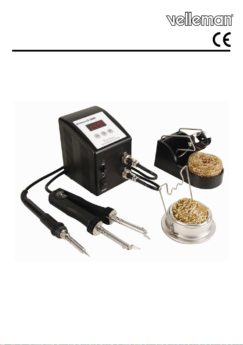
VTSSC72
MICRO DIGITAL REWORK SOLDERING STATION DIGITAAL REPARATIESTATION – 80 W/230 V
STATION DE RÉPARATION NUMÉRIQUE – 80 W/230 V
ESTACIÓN DE REPARACIÓN DIGITAL - 80W/230V
DIGITALE REPARATURSTATION - 80W/230V
USER MANUAL 3
GEBRUIKERSHANDLEIDING 7
NOTICE D’EMPLOI 12
MANUAL DEL USUARIO 16
BEDIENUNGSANLEITUNG 21
Page 2
VTSSC72
06.11.2012
2
©Velleman nv
Page 3
VTSSC72
disposal of the device after its lifecycle
Do not dispose of the unit (or batteries) as unsorted municipal waste; it should be taken to a
o a local recycling service.
Please read the manual thoroughly before bringing this device into
damaged in transit, don't install or use it and contact your dealer.
Do not use near inflammable products or in explosive atmospheres. Only use in properly
Do not touch the shaft or soldering tip as this can cause serious burns. Always re
soldering iron to its stand between uses; always let it cool down after use and before storage.
Always disconnect mains power when the device is not in use or when maintenance activities are
power cord by the plug only. Do not crimp the power cord(s) and protect
Do not inhale solder fumes. Dispose solder residue in accordance with local regulations.
Never use the device on live electronic circuits. Make sure power to the work piece is cut and
on the last pages of this manual.
this device away form rain, moisture, splashing and dripping
Keep this device away from dust and extreme heat. Make sure the ventilation openings
shocks and abuse. Avoid brute force when operating the
Familiarise yourself with the functions of the device before actually using it.
All modifications of the device are forbidden for safety reasons. Damage caused by user modifications
Only use the device for its intended purpose. Using the device in an unauthorised way will void the
Damage caused by disregard of certain guidelines in this manual is not covered by the warranty and
r will not accept responsibility for any ensuing defects or problems.
Do not switch the device on immediately after it has been exposed to changes in temperature.
Protect the device against damage by leaving it switched off until it has reached room temper
User manual
1. Introduction
To all residents of the European Union
Important environmental information about this product
This symbol on the device or the package indicates that
could harm the environment.
specialized company for recycling.
This device should be returned to your distributor or t
Respect the local environmental rules.
If in doubt, contact your local waste disposal authorities.
Thank you for choosing Velleman!
service. If the device was
The VTSSC72 comes with:
1x soldering station + power cord
1x soldering iron + tip and stand with tip cleaner
1x soldering tweezers + tip and stand with tip cleaner
2. Safety Instructions
Keep this device away from children and unauthorized users.
ventilated rooms.
Incorrect use may cause fire.
performed. Handle the
against damage. Have an authorised dealer replace it if necessary.
turn the
capacitors are discharged.
3. General Guidelines
Refer to the Velleman® Service and Quality Warranty
Indoor use only. Keep
liquids. Never put object filled with liquid on top.
are clear at all times.
Protect this device from
device.
•
•
to the device is not covered by the warranty.
•
warranty.
•
the deale
•
06.11.2012
3
©Velleman nv
ature.
Page 4
VTSSC72
VTSSC72
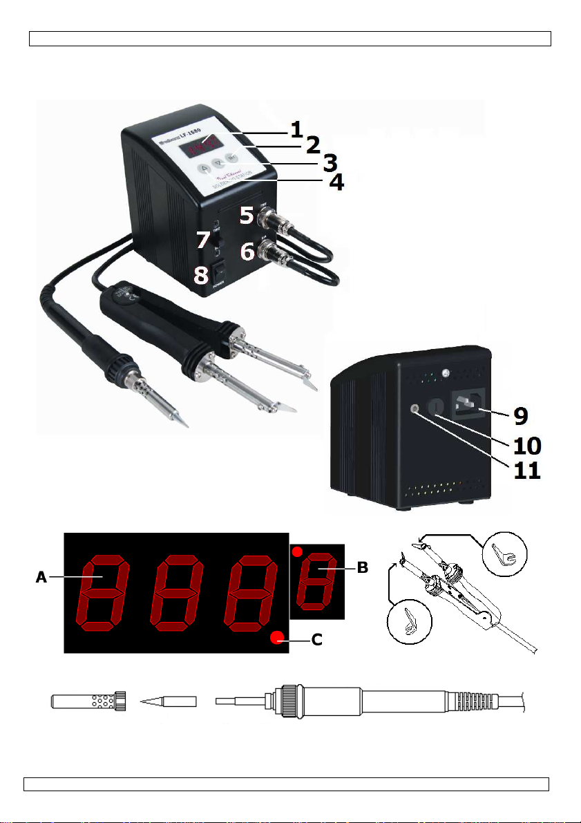
6
soldering iron connection (SIA)
1 display
7
iron/tweezers switch
2 SET-button
8
power switch
3 down-button
(▼) 9 power connector
4 up-button
(▲) 10 fuse
5 soldering tweezers connection (TWZ)
11
earth jack
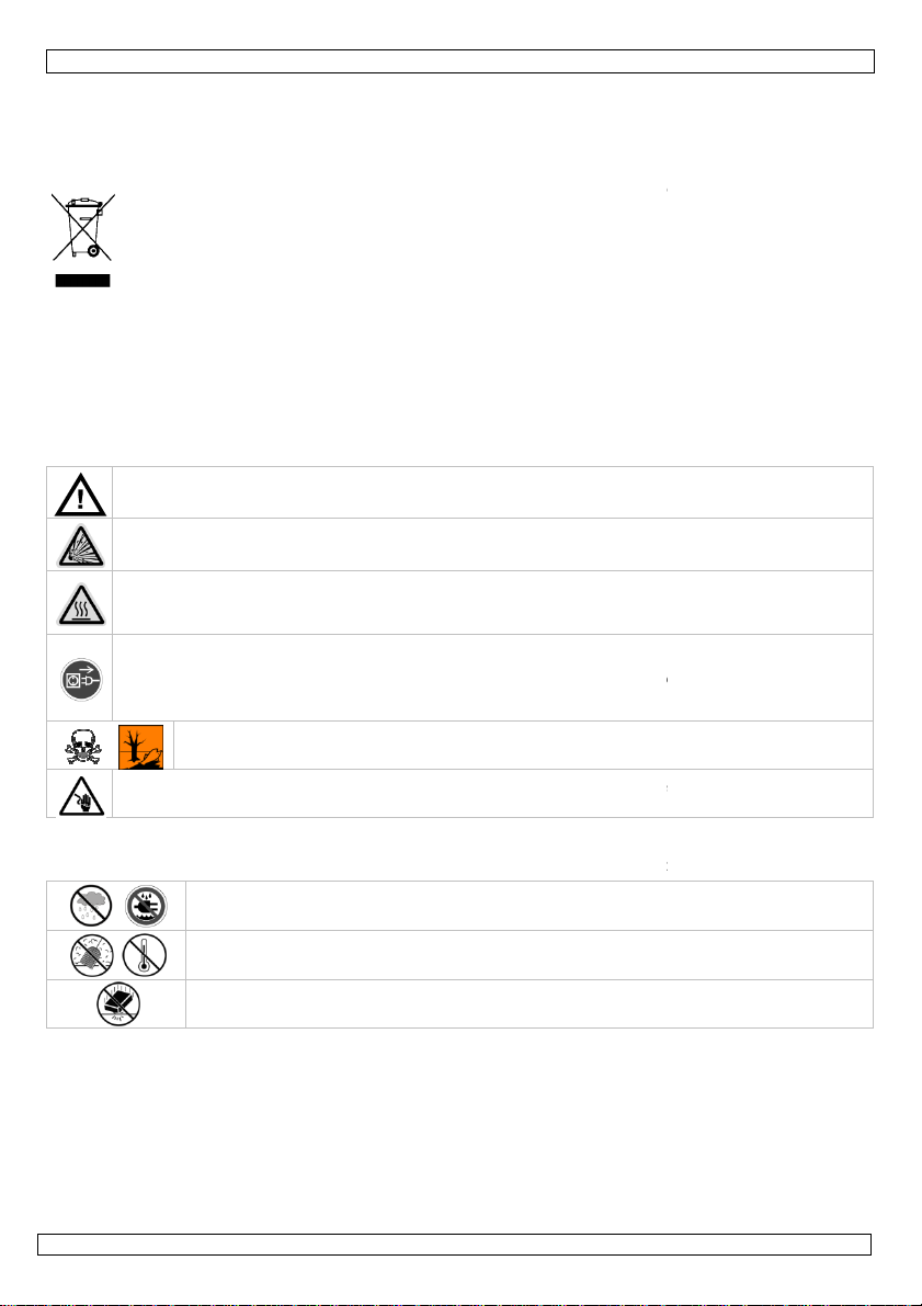
display
B
temperature unit (°C or °F)
A temperature indication
C
heating indication
4. Features
• electronic temperature control
• password lock
• sensor and heater fail notification
• LED display with digital temperature scale (°C or °F)
• with on/off switch
• ceramic heating element with temperature sensor
• HEATER/SENSOR FAILED DETECTION: if the sensor circuit fails, the display reads “S--E” and heater
power is cut. If heater circuit fails the display will read “H--E” and heater power is cut.
• TEMPERATUE “LOCK-OUT” FEATURE: the temperature can be locked with a password which might be
useful in a production line.
• ESD SAFE AND SPIKE FREE CIRCUITRY: the “Zero Voltage” electronic switching design also protects
voltage and current sensitive components (CMOS devices, etc.) against overcurrent and transient
voltage spikes.
• LIGHTWEIGHT SOLDERING IRON: ergonomic mini handle that stays cool and prevents operator
fatigue.
• isolated power supply: high-quality 32Vac transformer designed for lead-free soldering
• available options:
o spare soldering bits: 0.4mm (BITC03), 0.8mm (BITC201)
o spare soldering iron: VTSSC7/SP1
o spare SMD tweezers: VTSSC7/SP2
o spare tweezers bits: 2mm (BITTW2), 5mm (BITTW5), 15mm (BITTW15), 30mm (BITTW30)
5. Overview
Refer to the illustrations on page 2 of this manual.
6. Description
• This soldering station is designed to meet the present and future needs of the electronic production
industry. The VTSSD72 is engineered to meet the stringent demands of hobbyists, maintenance
personnel and production people alike.
• A high-quality sensor and heat transfer technology ensure precise temperature regulation which is
essential for making consistent, reliable soldered connections.
• The aluminium alloy housing has several advantages: strong, good heat sink and very resistant to
electro-magnetic interference.
• The VTSSD72s’ electronic circuitry enables the user to set soldering temperatures between 200 and
480°C (392 to 896°F) without having to replace the tip or the heating element. For tweezers, max.
temperature is slightly lower: 430~450°C (806~842°F). The temperature is maintained to within
±3°C (± 6°F) of the normal operating temperature by a thermocouple sensor placed in the head of
the heating element. The 80W power results in a rapid heat-up and fast recovery.
• The revolutionary "zero voltage" switching design also protects voltage- and current-sensitive
components (CMOS devices, etc.) against the damaging current and transient voltage spikes
commonly produced by less efficient, mechanically switched stations. The heating elements are
galvanically isolated from the electrical supply by an isolating transformer that prevents the system
from using a max. tension higher than a (safe) 32VAC.
06.11.2012 ©Velleman nv
4
Page 5
VTSSC72
leaded solder
lead-free
Melting point
215°C
(419°F)
220°C (428°F)
Normal Operation
270-320°C (518
-
608°F)
300-360°C (572
-
680°F)
Production Line Operation
320-380°C (608
-
716°F)
360-410°C (680
-
770°F)
7. Operating Temperature
The most common soldering alloys used in the electronics industry consist of 60% tin and 40% lead. The
operating temperature of this type of solder is detailed below and can vary from manufacturer to
manufacturer. However, to meet RoHS requirements, these solders are no longer allowed and are
replaced by lead-free solders that require a working temperature which is ±30°C (54°F) higher.
A good joint is assured if the iron's operating temperature is set within the parameters suitable for the
type of solder being used. The solder will flow too slowly if the temperature is too low; if the temperature
is too high, the flux in the solder may burn which will give rise to billowing white smoke. In turn, this will
result in a dry joint or in permanent damage to the PCB.
8. Operating instructions
Refer to the illustrations on page 2 of this manual.
Verify whether the operating voltage of the unit is identical to that of the electrical supply.
GENERAL
• Make sure the unit's power switch [8] is in the "OFF"-position.
• Plug in the soldering tweezers [5] and iron [6]. Note that the connectors have a notch so they only
fit in one way. Do not force.
• Connect the AC power cord to the power connector [9]. Connect the other end to a suitable mains
outlet.
• When applicable, connect an earth wrist strap to the earth jack [11] at the back of the station.
PARAMETER SETTINGS
• Switch on the station [8].
• Set the iron/tweezers switch [7] to TWZ for tweezers parameter settings or to SIA for regular
soldering iron configuration.
• Press the SET-button [2] and hold for at least 5 seconds until the display shows “— — —”
(flashing).Use the ▲-button [4] to enter the mode lock password “010” (default) and press the setbutton [2] to go into setup menu. A wrong password will return to normal working mode
(temperature indication).
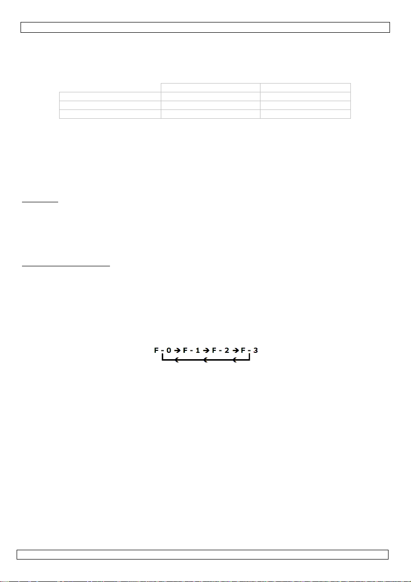
• In the setup menu, the display will show “F-0”. Press the ▲[4]- or ▼ [3]-button to select modes. If
no button is pressed within 15 seconds the device will return to normal operation mode.
• F-0: exit menu mode
Press the SET-button [2] when the display shows F-0 to exit the setup menu and return to
temperature indication.
• F-1: password mode
When password mode is enabled, the user can not change the temperature settings on the
station unless he or she knows the password.
Press the set-button [2] once to enter password mode. Press the ▲[4]- or ▼ [3]-button to
change display between 000 and 100, with 000 indicating password mode disabled and 100
indicating password enabled. Press the set-button [2] to return to the setup menu.
• F-2: temperature correction mode
Press the set-button [2] once to enter temperature correction mode. Press the ▲[4]- or ▼ [3]button to enter a correction factor for the temperature, e.g. when the display shows 300°C but
the actual temperature is only 290°C, add 10°C to the shown correction value.
When in °C Negative values are indicated with a minus in front.; in °F negative values are
indicated by a blinking display (5s interval). Press the set-button [2] to return to the setup
menu.
• F-3: unit of temperature
Press the set-button [2] once to enter temperature mode. Press the ▲[4]- or ▼ [3]-button to
change between °C and °F. Press the set-button [2] to return to the setup menu.
06.11.2012 ©Velleman nv
5
Page 6

VTSSC72
SOLDERING
IMPORTANT NOTE
Do not use temperatures in excess of 410°C (770°F) for normal soldering purposes. The device can be
used at higher temperatures for short periods of time. EXERCISE GREAT CAUTION WHEN DOING SO.
CAUTION
Do not touch the metal parts of the soldering iron while the unit is being used or while it is cooling in
order to avoid burns.
• Set the power switch [8] to the “ON”-position.
• Set the iron/tweezers switch [7] to TWZ for tweezers parameter settings or to SIA for regular
soldering iron configuration.
• Press the up-button (▲) [4] until the display [1] indicates 250°C (or 482°F). When the temperature
is stable, the heating indication [C] is off. The unit [B] is shown next to the temperature [A].
Note: to change the indicated unit, see § parameter settings above.
• Tin the surface of the soldering tip by applying a new protective layer of solder.
• Set the iron or tweezers to the desired working temperature.
• When using the tweezers, always lift components perpendicular to the PCB.
• Always return the soldering iron and tweezers to their stand between uses.
9. Common causes for tip failure
• The temperature of the tip exceeds 410°C (770°F)
• The tip is not sufficiently tinned
• Wiping the tip on a surface with a high sulphur content or on a dirty or dry sponge
• Contact with organic or chemical substances such as plastic, resin, silicone and grease
• Impurities in the solder and/or a low tin content
10. Tip maintenance
The soldering iron and tweezers use extremely high temperatures. Make sure that the unit is switched off
for maintenance purposes.
Remove the tip and clean it after heavy or moderate use. We recommend cleaning the tip daily if the
station is used frequently.
The supplied soldering tip is made of copper covered with a layer of iron. It will retain its projected life
span if used properly.
• Always tin the tip before returning it to the holder, prior to turning off the station or to storing it for
long periods of time. Wipe the tip on a wet sponge or use our tip cleaner before activating the device.
• Using excessive temperatures (more than 400°C or 750°F) will shorten the life span of the tip.
• Do not exercise excessive pressure on the tip while soldering, as this may cause damage to the tip.
• Never clean the tip with a file or with abrasive materials.
• Do not use flux containing chloride or acid. Use only resinous fluxes.
• If an oxide film has formed, you should remove it by buffing carefully with a 600-800 grit emery
cloth or by using isopropyl alcohol and consequently applying a new protective layer of solder.
• Set the desired temperature after allowing the unit to idle at 250°C for three minutes. The station
will be ready for use once the set temperature is reached.
IMPORTANT
Remove and clean the tip daily. Remove excess solder from the barrel nut assembly when installing a
new tip, otherwise the tip may be fused to the heating element or to the retaining assembly.
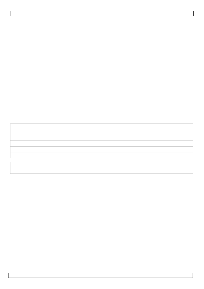
11. Maintenance
• Soldering tips can be replaced simply by unscrewing the barrel nut assembly. Turn off the station and
allow it to cool down first. Damage to the soldering station may occur if the system is left on and the
removed tip has not been replaced.
• After removing the tip, you should blow out any oxide dust that may have formed in the tip
receptacle. Be careful not to get dust in your eyes. Replace the tip and tighten the screw. Pliers can
be used to avoid contact with hot surfaces BUT SHOULD BE USED WITH CAUTION because overtightening may cause damage to the element or fuse the tip to the element.
• Tweezers tips can be replaced by releasing the screws on top. Make sure to align the new tips
properly and do not tighten the screws to hard to avoid damage.
• The outer cover of the tweezers, iron and station may be cleaned with a damp cloth using small
amounts of liquid detergent. Never submerse the unit in liquid or allow any liquid to enter the case of
the station. Never use any solvent to clean the case.
• If the tweezers, iron or station should become faulty or, for some reason does not operate normally,
the system should be returned to the service department of your authorized dealer or service agent.
06.11.2012 ©Velleman nv
6
Page 7
VTSSC72
max. heater power for soldering iron
80W
iron 200 –
480°C (392
– 896°F)
tweezers
200 –
450°C (392
– 842°F)
voltage iron
/tweezers
32V AC
weight
4kg
dimensions
90 x 110 x 130mm
Velleman nv cannot be held responsible in the
For more info
he infor
All worldwide rights reserved.
No part of this manual may be copied, reproduced, translated or reduced to any electronic medium or otherwise without
Dit symbool op het toestel of de verpakking geeft aan dat, als het na zijn levenscyclus wordt
weggeworpen, dit toestel schade kan toebrengen aan het milieu. Gooi dit toestel (en eventuele
gewone huishoudelijke afval; het moet bij een gespecialiseerd bedrijf
terechtkomen voor recyclage. U moet dit toestel naar uw verdeler of naar een lokaal
aatselijke autoriteiten inzake verwijdering.
Dank u voor uw aankoop! Lees deze handleiding grondig voor u het toestel in gebruik neemt. Werd het
het dan niet en raadpleeg uw dealer.
explosieve gassen. Gebruik enkel in
Raak de schacht of de punt van een ingeschakelde (de)soldeerbout nooit aan. Plaats na
gebruik de bout altijd terug in de houder en laat afkoelen alvorens hem op te bergen.
Ontkoppel van het lichtnet na gebruik of alvorens onderhoudswerkzaamheden uit te voeren.
Neem de voedingskabel enkel bij de stekker vast. De voedingskabel mag niet omgeplooid of
nieuwe kabel plaatsen.
Adem de vrijgekomen dampen nooit in. Gooi soldeerresidu weg volgens de plaatselijke
Gebruik dit toestel nooit op een elektronisch circuit onder spanning. Schakel eerst de
12. Technical specifications
temperature range
Use this device with original accessories only.
event of damage or injury resulted from (incorrect) use of this device.
concerning this product, please visit our website www.velleman.eu. T
manual is subject to change without prior notice.
© COPYRIGHT NOTICE
This manual is copyrighted. The copyright to this manual is owned by Velleman nv.
the prior written consent of the copyright holder.
GEBRUIKERSHANDLEIDING
1. Inleiding
Aan alle ingezetenen van de Europese Unie
Belangrijke milieu-informatie betreffende dit product
batterijen) niet bij het
recyclagepunt brengen. Respecteer de plaatselijke milieuwetgeving.
Hebt u vragen, contacteer dan de pl
mation in this
toestel beschadigd tijdens het transport, installeer
Inhoud:
1x soldeerstation + voedingskabel
1x soldeerbout + punt en houder met puntreiniger
1x SMD-pincet + punt en houder met puntreiniger
2. Veiligheidsinstructies
Houd buiten het bereik van kinderen en onbevoegden.
Vermijd gebruik in de buurt van brandbare producten of
een goed geventileerde ruimte.
verkeerd gebruik ontstaat brandgevaar.
beschadigd zijn. Laat uw dealer zo nodig een
milieuwetgeving.
voeding van het circuit uit en ontlaad alle condensatoren.
06.11.2012
7
©Velleman nv
Bij
Page 8
VTSSC72
achteraan deze handleiding.
Bescherm tegen regen, vochtigheid en
objecten gevuld met vloeistof op het toestel.
Bescherm tegen stof en extreme hitte. Zorg dat de verluchtingsopeningen niet verstopt
Bescherm tegen schokken. Vermijd brute kracht tijdens de bediening
Om veiligheidsredenen mag u geen wijzigingen aanbrengen. Schade door wijzigingen die de
g gebruik vervalt de garantie.
De garantie geldt niet voor schade door het negeren van bepaalde richtlijnen in deze handleiding en
uw dealer zal de verantwoordelijkheid afwijzen voor defecten of problemen die hier rechtstreeks
diging te vermijden, zet u het toestel best niet aan onmiddellijk nadat het werd
blootgesteld aan temperatuurschommelingen. Wacht tot het toestel op kamertemperatuur gekomen
EN DE SENSOR: Bij storing van de sensor
E’ weer en zal het verwarmingselement uitschakelen. Bij storing van het
E’ weer en zal het verwarmingselement uitschakelen.
URSINSTELLING: Dit station heeft een vergrendelbare
STROOMPIEKVRIJ CIRCUIT: Geen storing van gevoelige onderdelen zoals CMOS
LICHTGEWICHT SOLDEERBOUT: Het kleine, ergonomische handvat wordt niet warm en is geschikt
VAC speciaal ontworpen voor het solderen
tuur: temperatuur van de punt is nauwkeurig tot op ± 3°C (6°F).
15mm (BITTW15), 30mm
VTSSC72
6
aansluiting soldeerbout (SIA)
1 display
7
schakelaar soldeerbout
2 instelknop SET
8
aan-uitschakelaar
3
▼-
knop 9 voedingsaansluiting
4
▲-
knop 10 zekering
5 aansluiting voor
soldeer
pincet
(TWZ)
11 aardingsaansluiting
/-pincet
3. Algemene richtlijnen
Raadpleeg de Velleman® service- en kwaliteitsgarantie
Gebruik het toestel enkel binnenshuis.
opspattende vloeistoffen. Plaats geen
geraken.
•
Leer eerst de functies van het toestel kennen voor u het gaat gebruiken.
•
gebruiker heeft aangebracht valt niet onder de garantie.
•
Gebruik het toestel enkel waarvoor het gemaakt is. Bij onoordeelkundi
•
verband mee houden.
•
Om bescha
is.
4. Eigenschappen
• elektronische temperatuurregeling
• vergrendeling van de temperatuurregeling via paswoord
• verklikker bij defecte sensor of verwarmingselement
• LED display met digitale temperatuurschaal (°C of °F)
• met on/off schakelaar
• keramisch verwarmingselement met temperatuursensor
• STORINGSDETECTOR VOOR HET VERWARMINGSELEMENT
geeft de display ‘S-verwarmingselement geeft de display ‘H--
• VERGRENDELING VAN DE TEMPERATU
temperatuursinstelling via paswoord. Dit is handig aan de montagelijn.
•
dankzij het geaarde ontwerp en de nuldoorgangsschakeling.
•
voor langdurig gebruik.
• Geïsoleerde voeding: hoogwaardige transformator van 32
zonder lood.
• Stabiliteit van tempera
• Opties:
o reservedesoldeerpunten: 0,4 mm (BITC03), 0,8 mm (BITC201)
o reservesoldeerbout: VTSSC7/SP1
o pincet voor SMD-componenten: VTSSC7/SP2
o reservepunten voor SMD-pincet: (BITTW2), 5mm (BITTW5),
(BITTW30)
5. Omschrijving
Raadpleeg de figuren op pagina 2 van deze handleiding.
.
-componenten
06.11.2012
8
©Velleman nv
Page 9
VTSSC72
display
B
temperatuureenheid (°C of °F)
A temperatuuraanduiding
C
opwarmingsaanduiding
loodsoldeer
loodvrij soldeer
Smeltpunt
215°C
(419°F)
220°C (428°F)
Normale werking
270-320°C (518
-
608°F)
300-360°C (572
-
680°F)
Productiedoeleinden
320-380°C (608
-
716°F)
360-410°C
(680-770°F)
6. Beschrijving
• Dit soldeerstation werd ontworpen met het oog op de huidige en toekomstige kwaliteitseisen van de
elektronica-industrie. De VTSSC72 voldoet dus ruimschoots aan de eisen van hobbyisten,
onderhoudspersoneel en productiepersoneel.
• Dankzij de hoogwaardige sensor en hitteoverdrachttechnologie, die zorgen voor een precieze
temperatuurregeling, kunt u betrouwbare soldeerpunten maken.
• De behuizing in aluminium is stevig, de koelt het toestel op een efficiënte manier en houdt
elektromagnetische stralen tegen.
• Dankzij het elektronische systeem van de VTSSC72 kunt u soldeertemperaturen instellen van 200
tot 480°C (392 tot 896°F) waarbij u noch de punt, noch het verwarmingselement hoeft te vervangen.
Het solderrpincet heeft een lagere bedrijfstemperatuur: 430 tot 450°C (806 tot 842°F). De
temperatuur wordt binnen een marge van ± 3°C (± 6°F) van de normale bedrijfstemperatuur
gehouden dankzij het thermokoppel in verwarmingselement. Het vermogen van 80 W zorgt voor een
snelle ideale bedrijfstemperatuur.
• De revolutionaire ‘nuldoorgangsschakeling’ beschermt gevoelige componenten (CMOS-apparaten,
enz.) tegen de stroomstoten en spanningpieken die bij minder efficiënte, mechanisch geschakelde
stations dikwijls leiden tot beschadiging. De verwarmingselementen zijn galvanisch gescheiden van
het net door een scheidingstransformator die het systeem een veilige maximale spanning van 32 VAC
laat gebruiken.
7. Bedrijfstemperatuur
De meest gebruikte soldeerlegeringen in de elektronica-industrie bestaan uit 60% tin en 40% lood.
Hieronder vindt u de werktemperatuur van dit type soldeer. Die temperatuur kan verschillen van
fabrikant tot fabrikant. De Europese RoHS-standaard verbiedt echter het gebruik en de verkoop van
loodsoldeer. Het toegelaten loodvrije soldeer smelt aan een temperatuur die gemiddeld 30°C (54°F)
hoger ligt dan dat van loodsoldeer.
Een goede verbinding is verzekerd indien de werktemperatuur van de soldeerbout is afgestemd op de
werktemperatuur van het type soldeer dat u gebruikt. Het soldeer zal te traag vloeien bij een te lage
temperatuur; een te hoge temperatuur verbrandt de flux in het soldeer en veroorzaakt een hevige
rookontwikkeling. Dit leidt dan weer tot een droge verbinding of tot permanente beschadiging van de
printplaat.
8. Bedieningsinstructies
Raadpleeg de figuren op pagina 2 van deze handleiding.
Controleer of de werkspanning van het toestel identiek is aan die van de stroomvoorziening. Ga na of het
toestel niet werd beschadigd tijdens het transport.
ALGEMEEN
1. Plaats de voedingsschakelaar [8] op OFF.
2. Plug voorzichtig de soldeerbout [6] en SMD-pincet [5] in. Door de inkeping kunt u ze op slechts een
enkele manier aansluiten.
3. Sluit de voedingskabel aan op de voedingsaansluiting [9]. Steek de stekker in het stopcontact.
4. Sluit indien gewenst een antistatische armband aan de aardinsaansluiting [11] achteraan het toestel.
INSTELLINGEN
• Schakel het station in [8].
• Plaats de schakelaar [7] op TWZ indien u het pincet of op SIA indien u de gewonde soldeerbout
gebruikt.
• Houd SET [2] gedurende minstens 5 seconden ingedrukt tot ‘— — —’ op de display knippert. Geef
het paswoord (het standaard paswoord is ‘010’) in met ▲ [4] en druk op SET [2] om het instelmenu
weer te geven. Bij het invoeren van een ongeldig paswoord keert u terug naar de normale
werkmodus (temperatuuraanduiding).
• In het instelmenu zal de display ‘F-0’ weergeven. Selecteer de modus met ▲ [4] of ▼ [3]. Na 15
06.11.2012 ©Velleman nv
9
Page 10

VTSSC72
seconden keert het station terug naar de normale werkmodus.
• F-0: verlaten van het menu
Verlaat het instelmenu met SET [2]. U keert terug naar de temperatuurweergave.
• F-1: instellen van het paswoord
Wanneer de paswoordmodus ingeschakeld is, kan de gebruiker de temperatuursinstelling niet
wijzigen zonder eerst het paswoord ingevoerd te hebben.
Druk op SET [2] om het paswoordmenu weer te geven. Selecteer nu 000 (paswoord
uitgeschakeld) of 100 (paswoord ingeschakeld) met ▲ [4] of ▼ [3]. Druk opnieuw op SET [2]
om naar het instelmenu terug te keren.
• F-2: temperatuursinstelling
Druk op SET [2] om het instelmenu voor de temperatuur weer te geven. Geef de correctiemarge
in met ▲ [4] of ▼ [3]. Wanneer de weergegeven temperatuur afwijkt van de reële temperatuur
van de punt, kunt u de weergave hier ijken. Voorbeeld: weergegeven temperatuur = 300°C,
reële temperatuur van de punt = 290°C, voeg 10°C toe.
Een negatieve Celsiuswaarde wordt aangeduid met een minteken; een negatieve
Fahrenheitwaarde zal knipperen. Druk op SET [2] om naar het algemeen instelmenu terug te
keren.
• F-3: selecteren van de temperatuureenheid
Druk op SET [2] om het instelmenu weer te geven. Selecteer nu de eenheid (°C of °F ) met
▲[4] of ▼ [3]. Druk op SET [2] om naar het algemeen instelmenu terug te keren.
SOLDEREN
BELANGRIJKE OPMERKING
Bij het solderen mag u geen temperaturen gebruiken die de 410°C (770°F) overstijgen. U kunt het
toestel wel kortstondig gebruiken bij hogere temperaturen, maar dan moet u heel voorzichtig zijn.
OPGELET
Om brandwonden te vermijden mag u de metalen delen van de soldeer- en de desoldeerbout niet
aanraken tijdens gebruik of wanneer ze aan het afkoelen zijn.
• Plaats de voedingsschakelaar [8] op ON.
• Plaats de schakelaar [7] op TWZ indien u het pincet of op SIA indien u de gewonde soldeerbout
gebruikt.
• Druk op ▲ [4] onderaan de soldeerdisplay tot deze display de waarde 250°C weergeeft. Houd ▲ [4]
of ▼ [3] ingedrukt om de waarde sneller te wijzigen. Tijdens het opwarmen van de bout zal de
opwarmingsaanduiding op de display [C] knipperen. De eenheid [B] staat naast de temperatuur [A]
weergegeven. Opmerking: Raadpleeg de paragraaf hierboven om de eenheid te wijzigen.
• Vertin het oppervlak van de soldeerpunt en de desoldeerpunt door een nieuw beschermend laagje
soldeer aan te brengen.
• Stel de gewenste temperaturen in.
• Bij het gebruik van het pincet, verwijder het component door het loodrecht uit de printplaat te
trekken.
• Plaats na gebruik de soldeerbout en SMD-pincet altijd terug in de houders.
9. Defecte punt: mogelijke oorzaken
• De temperatuur van de punt is hoger dan 410°C (770°F).
• De stiftpunt is onvoldoende vertind.
• De punt is in contact gekomen met een vuile of droge spons of met een oppervlak met een te hoog
zwavelgehalte.
• Contact met organische of chemische stoffen zoals plastic, hars, vetten en siliconen.
• Onzuiverheden in het soldeer en/of soldeer met een te laag tingehalte.
10. Tips voor het onderhoud van de punt
De soldeerbout en SMD-pincet maken gebruik van extreem hoge temperaturen. Schakel het toestel uit
wanneer u het wil reinigen.
Verwijder en reinig de punt na intensief gebruik. U moet de punt dagelijks reinigen indien u het toestel
frequent gebruikt.
De meegeleverde soldeerpunt is vervaardigd uit koper bekleed met ijzer. De levensduur blijft enkel
behouden indien u ze gebruikt zoals het hoort.
06.11.2012 ©Velleman nv
10
Page 11
VTSSC72
max. vermogen van het
verwarmingselement
80 W
soldeerbout
200 –
480°C
SMD-pincet
200 –
450°C
spanning soldeerbout/SMD
-
pincet
32
VAC
gewicht
4 kg
afmetingen
90 x 110 x 130
mm
• U moet de punt altijd vertinnen vóór u hem terug in de houder plaatst, vóór u het apparaat
uitschakelt of bij lange periodes van inactiviteit. Veeg de punt schoon met een natte spons vóór u
begint of gebruik onze reinigingsspons.
• De levensduur van de punt vermindert indien u te hoge temperaturen gebruikt (hoger dan 400°C of
750°F).
• Duw niet te hard op de punt tijdens het solderen om beschadiging te vermijden.
• Gebruik geen vijlen of schurende materialen om de punt te reinigen.
• Gebruik geen vloeimiddelen die chloride of zuur bevatten. Gebruik enkel harshoudende
vloeimiddelen.
• Verwijder eventuele oxidelaagjes door voorzichtig te polijsten met een amarildoek met korrel 600 –
800. U kunt ook isopropylalcohol gebruiken en vervolgens een nieuw laagje soldeer aanbrengen.
• Laat het toestel opwarmen tot 250°C (482°F) en stel na een drietal minuten de gewenste
temperatuur in. Het toestel is gebruiksklaar wanneer de ingestelde temperatuur wordt bereikt.
BELANGRIJK
Reinig de punt dagelijks. Verwijder overtollig soldeer van de stiftvergrendeling en de stiftpunt, anders
kan de punt samensmelten met het verwarmingselement of met de stiftvergrendeling.
11. Onderhoud
• Om de soldeerpunt te vervangen hoeft u enkel de stiftvergrendeling los te schroeven. Schakel het
toestel eerst uit om het te laten afkoelen. Het toestel kan worden beschadigd indien het systeem is
ingeschakeld en de verwijderde punt niet werd vervangen.
• Blaas het oxidestof in de stifthouder weg wanneer u de punt heeft verwijderd. Bescherm uw ogen
tegen dit stof. Vervang de punt en draai de schroef vast. U kunt een tang gebruiken om elk contact
met hete oppervlakken te vermijden. WEES ECHTER VOORZICHTIG: indien u de schroef te hard
aanspant, kan het verwarmingselement worden beschadigd of kunnen het element en de punt
worden samengesmolten.
• Vervanging van de punten van het pincet: Draai de schroeven bovenaan los. Zorg ervoor dat de
nieuwe punten mooi in de lijn van de stang zitten en draai daarna de schroeven niet te hard vqst.
• Maak de soldeerbout/SMD-pincet en het toestel schoon met een vochtige doek een kleine
hoeveelheid mild reinigingsmiddel. Dompel het toestel nooit in een vloeistof onder en zorg ervoor dat
er geen vloeistof in de behuizing kan binnensijpelen. Gebruik geen solventen.
• Breng een defect toestel terug naar uw verdeler of agent.
12. Technische specificaties
temperatuurbereik
Gebruik dit toestel enkel met originele accessoires. Velleman nv is niet aansprakelijk voor
schade of kwetsuren bij (verkeerd) gebruik van dit toestel. Voor meer informatie over dit
product en de meest recente versie van deze handleiding, zie www.velleman.eu. De informatie
in deze handleiding kan te allen tijde worden gewijzigd zonder voorafgaande kennisgeving.
© AUTEURSRECHT
Velleman nv heeft het auteursrecht voor deze handleiding.
Alle wereldwijde rechten voorbehouden. Het is niet toegestaan om deze handleiding of gedeelten ervan over te nemen, te
kopiëren, te vertalen, te bewerken en op te slaan op een elektronisch medium zonder voorafgaande schriftelijke
toestemming van de rechthebbende.
06.11.2012 ©Velleman nv
11
Page 12

VTSSC72
Des informations environnementales importantes concernant ce produit
Ce symbole sur l'appareil ou l'emballage indique que l’élimination d’un appareil en fin de vie
peut polluer l'environnement. Ne pas jeter un appareil électrique ou éle
; une déchèterie traitera
l’appareil en question. Renvoyer les équipements usagés à votre fournisseur ou à un service de
la réglementation locale relative à la protection de
! Lire la présente notice attentivement avant la mise en service de
Si l’appareil a été endommagé pendant le transport, ne pas l’installer et consulter votre
fer à souder + panne et support avec laine d’acier pour le nettoyage
CMS + panne et support avec laine d’acier pour le nettoyage
Éviter l’usage à proximité de produits inflammables ou de gaz explosifs. N’utiliser que dans un
Ne pas toucher la tige ni la panne afin d’éviter tout risque de brûlures. Placer le fer à souder ou à
dessouder dans le support après usage. Laisser refroidir le fer avant le stockage.
Déconnecter la station du réseau après usage ou avant tout travail d’entretien. Manier le cordon
d’alimentation par la fiche. Le câble d’alimentation ne peut pas être replissé ou endommagé.
’alimentation si nécessaire.
Ne jamais respirer les fumées de soudure. Éliminer les résidus de soudure en
respectant la réglementation locale relative à la protection de l’environnement.
Il est important de couper l’alimentation
à la fin de cette notice.
Protéger de la pluie, de l’humidité et des
projections d’eau. Ne jamais placer d’objet contenant un liquide sur l’appareil.
Protéger contre la poussière. Protéger contre la chaleur extrême. Veiller à ce que les
Protéger contre les chocs et le traiter avec circonspection pendant l’opération.
Toute modification est interdite pour des raisons de sécurité. Les dommages occasionnés par des
e impropre annule d'office la garantie.
La garantie ne s’applique pas aux dommages survenus en négligeant certaines directives de cette
notice et votre revendeur déclinera toute responsabilité pour les problèmes et les défauts qui en
cher l’appareil après exposition à des variations de température. Afin d’éviter des dommages,
attendre jusqu’à ce que l’appareil ait atteint la température ambiante avant de l’utiliser.
NOTICE D’EMPLOI
1. Introduction
Aux résidents de l'Union européenne
éventuelles) parmi les déchets municipaux non sujets au tri sélectif
recyclage local. Il convient de respecter
l’environnement.
En cas de questions, contacter les autorités locales pour élimination.
Nous vous remercions de votre achat
l’appareil.
revendeur.
Contenu :
1x station de soudage avec cordon d’alimentation
1x
1x pince à souder
2. Consignes de sécurité
Garder hors de la portée des enfants et des personnes non autorisées.
endroit bien ventilé.
incorrect peut engendrer des risques d’incendie.
Demander à votre revendeur de renouveler le câble d
Ne jamais utiliser la station sur un circuit sous tension.
vers le circuit et de décharger les condensateurs au préalable.
3. Directives générales
Se référer à la garantie de service et de qualité Velleman®
Utiliser cet appareil uniquement à l'intérieur.
ctronique (et des piles
Un usage
fentes de ventilation ne soient pas bloquées.
•
Se familiariser avec le fonctionnement avant l’emploi.
•
modifications par le client ne tombent pas sous la garantie.
•
N’utiliser qu’à sa fonction prévue. Un usag
•
résultent.
•
Ne pas bran
06.11.2012
12
©Velleman nv
Page 13

VTSSC72
VTSSC72
6
connexion du fer à souder (SIA)
1 afficheur
7
sélecteur fer
/
pince à souder
2 bouton SET
8
interrupteur marche/arrêt
3 bouton
9
prise d’alimentation
4 bouton
10
fusible
5 connexion pour pince à souder
(TWZ)
11
prise de terre
afficheur
B
unité
de température (°C ou °F)
A indication de la température
C
indication de réchauffement
4. Caractéristiques
• réglage de la température électronique
• verrouillage de la température avec mot de passe
• détecteur en cas de dérèglement du capteur ou de l’élément d’échauffement
• afficheur LED avec échelle de température numérique
• avec interrupteur on/off
• élément d'échauffement céramique avec capteur de température
• DISPOSITIF DE DÉTECTION EN CAS DE DÉRÈGLEMENT DE L’ÉLÉMENT DE CHAUFFE ET DU CAPTEUR :
L’afficheur affiche « S--E » et l’alimentation vers l’élément de chauffe est coupée dès un dérèglement
du capteur. En cas d’un dérèglement de l’élément de chauffe, l’afficheur affichera « H--E » et
l’alimentation vers l’élément de chauffe sera coupée.
• DISPOSITIF DE VERROUILLAGE DE LA TEMPÉRATURE : Il est possible de verrouiller la température
du fer à l’aide d’un mot de passe. Ceci est une fonction pratique pour toute application dans une
chaîne de production.
• PROTECTION CONTRE LES CRÊTES DE TENSION ET LES POINTES DE COURANT : Pas d’interférence
d’autres appareils grâce à la mise à la terre et la connexion « zero cross ».
• FER A SOUDER LÉGER : Les formes ergonomiques du fer à souder permettent une utilisation
prolongée. En outre, le manche ne se réchauffe pas pendant l’utilisation.
• Alimentation isolée : transformateur de 32 VCA haute qualité conçu pour le soudage sans plomb.
• Options
o pannes de rechange: 0,4 mm (BITC03), 0,8 mm (BITC201)
o fer à souder de rechange : VTSSC7/SP1
o pince à souder CMS : VTSSC7/SP2
o pannes de rechange pour pince SMD : 2mm (BITTW2), 5mm (BITTW5), 15mm (BITTW15),
30mm (BITTW30)
5. Description
Se référer aux illustrations à la page 2 de cette notice.
▼
▲
6. Emploi
• Cette station de soudage/dessoudage a été conçue afin de satisfaire aux exigences présentes et
futures du monde de l'électronique. La VTSSC72 convient donc parfaitement pour les hobbyistes
comme pour les services d'entretien et les ouvriers de production.
• Le capteur haute qualité et la technologie de transfert thermique efficace garantissent un réglage de
la température en précision, ce qui permet de réaliser de points de soudure fiables et consistantes.
• Le boîtier en aluminium est résistant, dissipe la chaleur et retient les interférences
électromagnétiques.
• La VTSSC72 est équipée d'une régulation électronique de la température de soudage entre 200 et
480°C (392 à 896°F) sans nécessiter un remplacement de la panne ou de l'élément d'échauffement.
La température de service de la pince est légèrement inférieure : 430 à 450°C (806 à 842°F). La
température est maintenue dans une marge de ± 3°C (± 6°F) de la température de service normale
à l’aide d’un thermocouple placé dans l’élément de chauffe. La puissance de 80 W suffit à amplement
à atteindre la température de service idéale.
• La connexion « zero cross » (quand le réseau passe par o) protège les composants sensibles (p.ex.
les appareils CMOS, etc.) contre les pointes de courant et les crêtes de tension qui, souvent, causent
des dégâts dans des stations commutées mécaniquement. Les éléments d'échauffement sont isolé
galvaniquement de la source d'alimentation par un transformateur de séparation qui permet au
système d'utiliser un maximum (sans risque) de 32 VCA.
06.11.2012 ©Velleman nv
13
Page 14

VTSSC72
étain avec plomb
étain sans plomb
Point de fusion
215°C
(419°F)
220°C (428°F)
Opération normale
270-320°C (518
-
608°F)
300-360°C (572
-
680°F)
Usage dans la production
320-380°C (608
-
716°F)
360-410°C (680
-
770°F)
7. Température de travail
La plupart des alliages de soudure dans le monde de l'électronique sont des alliages 60/40 (étain 60% plomb 40%). Ci-dessous vous trouverez la température de travail de ce type de soudure, une
température qui varie selon le fabricant. Cependant, la vente et l’utilisation d’étain avec plomb est, par la
norme RoHS, interdite en Union européenne. L’étain sans plomb nécessite une température plus élevée
de quelque 30°C (54°F).
Une bonne connexion est assurée si la température de travail du fer à souder correspond à la
température de travail du type de soudure employée. Une température trop basse amène une coulée
trop lente : le flux de la soudure risque de brûler en cas d'une température trop élevée, ce qui donne lieu
à une fumée dense. Cette fumée peut aboutir à une connexion sèche ou peut même occasionner un
endommagement permanent du circuit imprimé.
8. Instructions d'opération
Se référer à l’illustration à la page 2 de cette notice.
Vérifiez si la tension de travail de l'appareil est identique à celle de l'alimentation en électricité. Vérifiez si
l'appareil n'a pas été endommagé pendant le transport.
EN GÉNÉRAL
• Mettez l'interrupteur d'alimentation [8] dans la position OFF.
• Branchez les fers à souder [6] et la pince [5]. Notez que les fiches de connexion ont un cran et
qu’elles ne peuvent être insérées que d’une seule façon dans la connexion.
• Connectez le cordon d’alimentation à la prise [9]. Insérez la fiche d’alimentation dans une prise de
courant.
• Si nécessaire, connectez un bracelet antistatique à la prise de terre [11] à l’arrière de la station.
PARAMÉTRAGE
• Allumez la station [8]
• Placer le sélecteur [7] sur TWZ si vous utilisez la pince ou sur SIA si vous utilisez le fer à souder.
• Maintenez enfoncé le bouton SET [2] pendant au moins 5 secondes jusqu’à ce que « — — — »
clignote sur l’afficheur. Entrez le mot de passe (010 par défaut) avec le bouton ▲ [4] et renfoncez le
bouton SET [2] pour accéder au menu. Vous reviendrez au mode d’utilisation (affichage de la
température) lors de la saisie d’un mot de passe invalide.
• Une fois accédé au menu, l’afficheur affichera « F-0 ». Enfoncez le bouton ▲ [4] ou ▼ [3] pour
sélectionner le mode. La station revient au mode d’utilisation après une période de repos de 15
secondes.
• F-0 : quitter le menu
Enfoncez le bouton SET [2] lorsque l’afficheur affiche F-0 quitter le menu et revenir à l’affichage
de la température.
• F-1 : le mot de passe
Une fois le mot de passe activé, vous ne pourrez plus modifier la température de la panne.
Enfoncez le bouton SET [2] pour accéder au menu. Sélectionnez 000 (mot de passe désactivé)
ou 100 (mot de passe activé) avec le bouton ▲ [4] ou ▼ [3]. Renfoncez le bouton SET [2] pour
revenir au menu principal.
• F-2 : instauration de la température
Enfoncez le bouton SET [2] pour accéder au menu. Entrez la valeur corrective avec le bouton
▲ [4] ou ▼ [3]. Cette fonction permet détalonner l’afficheur lorsque la température affichée ne
correspond pas avec la température réelle de la panne. Exemple : température affichée = 300°C,
température réelle : 290°C, ajouter 10°C.
Une température °C négative est indiquée par un signe moins devant la valeur ; une température
°F négative clignotera. Renfoncez le bouton SET [2] pour revenir au menu principal.
• F-3 : unité de température
Enfoncez le bouton SET [2] pour accéder au menu. Sélectionnez l’unité de température (°C ou
°F) avec le bouton ▲ [4] ou ▼ [3]. Renfoncez le bouton SET [2] pour revenir au menu
principal.
06.11.2012 ©Velleman nv
14
Page 15

VTSSC72
SOUDAGE
REMARQUES IMPORTANTES
Évitez des températures supérieures à 410°C (770°F) lors du soudage. L'appareil se laisse
néanmoins utiliser à des températures plus élevées pendants des intervalles de courte durée.
AGISSEZ AVEC CIRCONSPECTION DANS CE CAS.
ATTENTION
Évitez les brûlures: ne touchez pas les parties métalliques du fer à souder lors de l'usage ou lorsqu'ils
sont en train de refroidir.
• Placez l'interrupteur d'alimentation [8] en position ON.
• Placer le sélecteur [7] sur TWZ si vous utilisez la pince ou sur SIA si vous utilisez le fer à souder.
• Enfoncez le bouton ▲ [4] sous l’afficheur jusqu’à ce qu’il affiche 250°C. Maintenez enfoncé le bouton
▲ [4] ou ▼ [3] pour modifier la température plus rapidement. L’indication de réchauffement [C]
clignote sur l’afficheur clignote lorsque la panne se réchauffe. L’unité [B] s’affiche à côté de la
température [A]. Remarque : Voir le paramètre ci-dessus pour sélectionner l’unité.
• Étamez la surface de la panne de soudage en appliquant une nouvelle couche protectrice de soudure.
• Réglez la température de service.
• En utilisant la pince, toujours retirer le composant du circuit en le soulevant de manière
perpendiculaire.
• Placez le fer à souder et la pince dans leur support après chaque usage.
9. Panne défectueuse : causes possibles
• La température de la panne dépasse 410°C (770°F)
• La panne n'est pas suffisamment étamée.
• La panne est entré en contact avec une éponge sèche ou sale ou avec une surface trop sulfureuse.
• Du contact avec des matières organiques ou chimiques comme le plastique, la résine, les graisses et
les silicones.
• Des impuretés dans la soudure et/ou de la soudure avec une teneur d'étain trop basse.
10. Entretien de la panne
Les fers à souder et la pince à souder CMS utilisent des températures très élevées. Débranchez l'appareil
avant de le nettoyer.
Enlevez et nettoyez la panne après chaque usage intensif. Nettoyez la panne chaque jour en cas d'une
utilisation fréquente.
Les pannes incluses sont faites en cuivre avec une couche de fer. Leur durée de vie reste optimale en cas
d'une utilisation appropriée.
• N'oubliez pas d'étamer la panne avant de la replacer dans son support, avant de débrancher
l'appareil ou lors d'une longue période d'inactivité. Avant de commencer, vous devez nettoyer la
panne à l'aide d'une éponge mouillée ou de notre nettoyant.
• La durée de vie de la panne sera raccourcie si vous employez des températures excessives (qui
dépassent donc 400°C ou 750°F).
• N'appuyez pas trop fort sur la panne pendant le soudage pour éviter tout endommagement.
• Évitez l'usage de limes et de matières abrasives lors du nettoyage de la panne.
• Évitez l'usage de fondants acidifères ou de fondants qui contiennent de la chlorure. N'utilisez que des
fondants résineux.
• Enlevez des couches d'oxyde en polissant prudemment avec du papier d'émeri avec un grain de 600
à 800. Vous pouvez également utiliser de l'alcool iso propyle et appliquer par la suite une nouvelle
couche protectrice de soudure.
• Vous pouvez instaurer la température désirée trois minutes après que l'appareil à atteint une
température de 250°C (482°F). La station de soudage/dessoudage est prêt à l'emploi dès que la
température instaurée est atteinte.
IMPORTANT
Nettoyez la panne journellement. Enlevez toute soudure superflue de la panne et du dispositif de
verrouillage. Sinon, vous risquez de faire fondre soit la panne et l'élément d'échauffement, soit la panne
et son dispositif de verrouillage.
11. Entretien
• La panne de soudage est facile à remplacer : vous n'avez qu'à dévisser le dispositif de verrouillage.
Débranchez d'abord l'appareil afin de garantir un refroidissement adéquat avant de remplacer la
panne. Vous risquez d'endommager l'appareil s'il reste branché sans que la panne soit remplacée.
06.11.2012 ©Velleman nv
15
Page 16

VTSSC72
Une fois la panne enlevée, vous devez souffler la poussière du support de la panne. N'oubliez pas de
eux ! Remplacez la panne et serrez la vis au moyen d'une pince afin d'éviter tout
: si la vis est trop serrée, vous risquez
et la station à l’aide d’un chiffon humide et un peu de
détergent. Ne jamais immerger les composants dans un liquide quelconque et veillez à ce qu’aucun
Contactez votre revendeur ou votre agent en cas d’une station de soudage défectueuse.
puissance max. du corps de chauffe
80 W
fer à souder
200 -
480°C
pince à souder CMS
200 –
450°C
tension fer/pince à souder
32 VCA
poids 4 kg
dimensions
90 x 110 x 130
mm
N’employer cet appareil qu’avec des accessoires d’origine. SA Velleman ne sera aucunement
responsable de dommages ou lésions survenus à un usage (incorrect) de cet appareil.
plus d’information concernant cet article et la version la plus récente de cette notice, visitez
Toutes les informations présentées dans cette notice
Toute reproduction, traduction, copie ou diffusion, intégrale ou partielle, du contenu de
que se soit est interdite sans l’accord préalable écrit de
Importantes informaciones sobre el medio ambiente concerniente a este producto
embalaje indica que, si tira las muestras inservibles, podrían
dañar el medio ambiente. No tire este aparato (ni las pilas, si las hubiera) en la basura
doméstica; debe ir a una empresa especializada en reciclaje. Devuelva este aparato a su
a la unidad de reciclaje local. Respete las leyes locales en relación con el medio
e las instrucciones del manual antes de usarla
Si el aparato ha sufrido algún daño en el transporte no lo instale y póngase en contacto con su
Mantenga el aparato lejos del alcance de personas no capacitadas y niños.
explosivo. Utilice sólo en un lugar
No toque el vástago ni la punta para evitar cualquier riesgo de quemaduras. Ponga el soldador
en el soporte después del uso. Deje que el soldador se enfríe antes de almacenarlo.
•
protéger vos y
contact avec des surfaces chaudes. ATTENTION
d'endommager l'élément ou de faire fondre l'élément et la panne.
•
• Nettoyez le fer à souder, la pince à souder CMS
liquide ne pénètre à l’intérieur du boîtier. Ne pas utiliser de solvants.
•
12. Spécifications techniques
plage de température
notre site web www.velleman.eu.
peuvent être modifiées sans notification préalable.
© DROITS D’AUTEUR
SA Velleman est l’ayant droit des droits d’auteur pour cette notice.
Tous droits mondiaux réservés.
cette notice par quelque procédé ou sur tout support électronique
l’ayant droit.
MANUAL DEL USUARIO
1. Introducción
A los ciudadanos de la Unión Europea
Este símbolo en este aparato o el
Pour
distribuidor o
ambiente.
Si tiene dudas, contacte con las autoridades locales para residuos.
Gracias por haber comprado la VTSSC72! Lea atentament
distribuidor.
Incluye:
1x estación de soldadura con cable de alimentación
1x soldador + punta y soporte con limpiador para puntas
1x pinzas SMD + punta y soporte con limpiador para puntas
2. Instrucciones de seguridad
No utilice el aparato cerca de productos inflamables o de gas
aireado.
incorrecto puede causar peligro de incendio.
06.11.2012
16
Un uso
©Velleman nv
.
Page 17

VTSSC72
Desconecte el aparato de la red eléctrica después del uso o antes de limpiarlo. Tire siempre del
enchufe para desconectar el cable de red, nunca del propio cable. No aplaste el cable de
daños causados por algún tipo de superficie afilada. Si
es necesario, pida a su distribuidor reemplazar el cable de alimentación.
Nunca respire los humos de soldadura. Tire los residuos de soldadura al respetar la
la protección del ambiente.
Nunca utilice el aparato si el circuito está bajo tensión. Primero desconecte la alimentación del
al final de este manual del usuario.
No exponga este equipo a lluvia, humedad ni
No exponga este equipo a polvo. No exponga este equipo a temperaturas extremas.
Asegúrese de que los orificios de ventilación no estén bloqueados.
No agite el aparato. Evite usar excesiva fuerza durante el manejo y la instalación.
Por razones de seguridad, las modificaciones no autorizadas del aparato están prohibidas. Los daños
causados por modificaciones no autorizadas, no están cubiertos por la garantía.
a las aplicaciones descritas en este manual. Su uso incorrecto anula la
Los daños causados por descuido de las instrucciones de seguridad de este manual invalidarán su
otros problemas resultantes.
No conecte el aparato si ha estado expuesto a grandes cambios de temperatura. Espere hasta que el
detector en caso de mal funcionamiento del elemento calentador y el sensor
FUNCIONAMIENTO DEL ELEMENTO CALENTADOR Y EL SENSOR: Se
» en la pantalla y se desactiva el elemento calentador si el sensor no funciona
correctamente. Si el elemento calentador no funciona correctamente, aparece «
BLOQUEO DEL AJUSTE DE LA TEMPERATURA: Es posible bloquear la temperatura del soldador con
una contraseña. Esto es una función práctica para cualquier aplicación de una cadena de producción.
E TENSIÓN Y LOS PICOS DE CORRIENTE: no hay
interferencias de otros aparatos gracias al diseño completamente puesto a tierra y la conmutación de
SOLDADOR LIGERO: Las formas ergonómicas del soldador permiten un uso pro
: transformador 32VAC de alta calidad diseñada para soldar sin plomo
: precisión de la temperatura de la punta hasta ±3°C
2mm (BITTW2), 5mm (BITTW5), 15mm (BITTW15),
alimentación y protéjalo contra posibles
reglamentación local con respecto a
circuito y descargue todos los condensadores.
3. Normas generales
Véase la Garantía de servicio y calidad Velleman ®
Utilice el aparato sólo en interiores.
ningún tipo de salpicadura o goteo.
• Familiarícese con el funcionamiento del aparato antes de utilizarlo.
•
• Utilice sólo el aparato par
garantía completamente.
•
garantía y su distribuidor no será responsable de ningún daño u
•
aparato llegue a la temperatura ambiente.
4. Características
• ajuste de la temperatura electrónico
• bloqueo de la temperatura con contraseña
•
• display LED con escala digital de la temperatura (°C o °F)
• con interruptor ON/OFF
• elemento calentador cerámico con sensor de temperatura
• DETECTOR EN CASO DE MAL
visualiza « S--E
y se desactiva el elemento calentador.
•
• PROTECCIÓN CONTRA LAS CRESTAS D
tensión « cruce de cero » (zero cross).
•
mango no se calienta durante el uso.
• alimentación aislada
• estabilidad de la temperatura
• opción
o puntas de soldadura de recambio: 0.4mm (BITC03), 0.8mm (BITC201)
o soldador de recambio: VTSSC7/SP1
o pinzas SMD: VTSSC7/SP2
o puntas de recambio para pinzas SMD:
30mm (BITTW30)
a
H--E » en la pantalla
longado. Además, el
06.11.2012
17
©Velleman nv
Page 18

VTSSC72
VTSSC72
6
conexión del soldador (SIA)
1 pantalla
7
selector soldador /pinzas SMD
2 botón SET
8
interruptor ON/OFF
3 botón
9
entrada de alimentación
4 botón
10
fusible
5 conexión para pinzas SMD (TWZ)
11
conexión a tierra
pantalla
B
unidad de temperatura (°C o °F)
A indicador de la temperatura
C
indicación de recalentamiento
estaño con plomo
estaño sin plomo
Punta de fusión
215°C
(419°F)
220°C (428°F)
Funcionamiento normal
270-320°C (518
-
608°F)
300-360°C (572
-
680°F)
Uso en la producción
320-380°C (608
-
716°F)
360-410°C (680
-
770°F)
5. Descripción
Véase las figuras en la página 2 de este manual del usuario.
▼
▲
6. Descripción
• Esta estación de soldadura ha sido diseñada para cumplir con los requisitos presentes y futuros del
mundo de la electrónica. La VTSSC72 resulta idónea no sólo para los aficionados sino también para
los servicios de mantenimiento y la producción.
• El sensor de alta calidad y la tecnología de transferencia de calor eficaz garantizan un ajuste de la
temperatura muy preciso, lo que permite realizar puntas de soldadura fiables y consistentes.
• La caja de aluminio es robusta, disipa el calor y retiene las interferencias electromagnéticas.
• La VTSSC72 está equipada con una regulación electrónica de la temperatura de soldadura entre 200
y 480°C (de 392 a 896°F) sin necesidad de cambiar la punta o el elemento calentador. La
temperatura de funcionamiento de las pinzas SMD es ligeramente inferior: 430~450°C (806~842°F).
La temperatura se mantiene en un margen de ± 3°C (± 6°F) de la temperatura de funcionamiento
normal gracias al termopar colocado en el elemento calentador. La potencia de 80W asegura un
alcance rápido de la temperatura de funcionamiento ideal.
• La conexión "cruce de cero" (si la red pasa por cero) protege los componentes sensibles (por ejemplo
los aparatos CMOS, etc.) contra los picos de corriente y las crestas de tensión que causan
normalmente daños en las estaciones conmutadas mecánicamente. Los elementos calentador están
aislados galvánicamente de la fuente de alimentación por un transformador de separación que
permite al sistema usar un máximo (sin riesgo) de 32VCA. Los soldadores y desoldadores están
equipados con un ajuste de temperatura que está en el panel frontal. Gracias a este ajuste, el
usuario puede ajustar la temperatura de manera fácil y eficaz.
7. Temperatura de funcionamiento
La mayoría de las aleaciones de soldadura en el mundo de la electrónica son aleaciones "60/40" (estaño
60% - plomo 40%). Véase abajo para la temperatura de trabajo de este tipo de soldadura, una
temperatura que varia según el fabricante. Sin embargo, la norma RoHS prohíbe la venta y el uso de
estaño con plomo en la Unión Europea. El estaño sin plomo necesita una temperatura más elevada de
unos 30°C (54°F).
Se asegura una buena soldadura si la temperatura de trabajo del soldador corresponde con la
temperatura de trabajo del tipo de estaño usado. Tenga en cuenta que una temperatura demasiada baja
causa un flux demasiado lento: a temperaturas muy elevadas, el flux del estaño se quema, lo que da
lugar a un humo denso. Este humo puede tener como resultado una soldadura seca o puede dañar
permanentemente el circuito impreso.
8. Instrucciones de funcionamiento
Véase la figura en la página 2 de este manual del usuario.
Verifique si la tensión eléctrica es la adecuada para el aparato. Verifique si el aparato no ha sido dañado
durante el transporte.
06.11.2012 ©Velleman nv
18
Page 19

VTSSC72
GENERAL
• Ponga el interruptor de alimentación [8] en la posición "OFF".
• Conecte el soldador [6] y las pinzas SMD [5]. A causa de la muesca sólo puede conectarlos de una
sola manera.
• Conecte el cable de alimentación a la entrada [9]. Conecte el aparato a la red eléctrica.
• Si fuera necesario, conecte una pulsera antiestática a la conexión a tierra [11] de la parte trasera de
la estación.
AJUSTES
• Active la estación [8].
• Ponga el selector [7] en la posición TWZ si utiliza las pinzas SMD o en la posición SIA si utiliza el
soldador.
• Mantenga pulsado el botón SET [2] durante al menos 5 segundos hasta que « — — — » parpadee en
la pantalla. Introduzca la contraseña (010 por defecto) con el botón ▲ [4] y vuelva a pulsar el botón
SET [2] para entrar en el menú. Volverá al modo de funcionamiento (visualización de la
temperatura) al introducir una contraseña inválida.
• Después de haber entrado en el menú, la pantalla visualiza « F-0 ». Pulse el botón ▲ [4] o ▼ [3]
para seleccionar el modo. La estación vuelve al modo de funcionamiento después de 15 segundos.
• F-0 : salir del menú
Pulse el botón SET [2] si la pantalla visualiza F-0 para salir del menú y volver a la visualización
de la temperatura.
• F-1 : la contraseña
Después de haber activado la contraseña, ya no puede modificar la temperatura de la punta.
Pulse el botón SET [2] para entrar en el menú. Seleccione 000 (contraseña desactivada) o 100
(contraseña activada) con el botón ▲ [4] o ▼ [3]. Vuelva a pulsar el botón SET [2] para volver
al menú principal.
• F-2 : ajustar la temperatura
Pulse el botón SET [2] para entrar en el menú. Introduzca el valor de corrección con el botón
▲ [4] o ▼ [3]. Esta función permite calibrar la pantalla si la temperatura visualizada no coincide
con la temperatura real de la punta. Ejemplo: temperatura visualizada = 300°C, temperatura
real: 290°C, añadir 10°C.
Una temperatura °C negativa está indicada por signo negativo delante del valor; una
temperatura °F negativa parpadeará. Vuelva a pulsar el botón SET [2] para volver al menú
principal.
• F-3 : unidad de temperatura
Pulse el botón SET [2] para entrar en el menú. Seleccione la unidad de temperatura (°C o °F)
con el botón ▲ [4] o ▼ [3]. Vuelva a pulsar el botón SET [2] para volver al menú principal.
SOLDAR
OBSERVACIONES IMPORTANTES
Evite temperaturas superiores a 410°C (770°F) al soldar. No obstante, puede usar el aparato a
temperaturas muy elevadas durante períodos cortos. EN ESTE CASO: SEA EXTREMADAMENTE
CUIDADOSO.
¡OJO!
Evite quemaduras: no toque las partes metálicas del soldador durante el uso o la refrigeración.
• Ponga el interruptor de alimentación [8] en la posición "ON".
• Ponga el selector [7] en la posición TWZ si utiliza las pinzas SMD o en la posición SIA si utiliza el
soldador.
• Pulse el botón ▲ [4] en la parte inferior izquierda de la pantalla hasta que visualiza 250°C.
Mantenga pulsado el botón ▲ [4] o ▼ [3] para modificar la temperatura de manera más rápida. La
indicación de recalentamiento [C] parpadea si la punta se recalienta. La unidad [B] se visualiza al
lado de la temperatura [A]. Nota: Véase arriba para seleccionar la unidad.
• Aplique una nueva capa de protección de estaño en la superficie de la punta del soldador.
• Ajuste la temperatura de funcionamiento.
• Al utilizar las pinzas SMD, saque siempre el componente del circuito al levantarlo de manera
perpendicular
• Ponga el soldador y la pinza en su soporte correspondiente después de cada uso.
06.11.2012 ©Velleman nv
19
Page 20

VTSSC72
9. Punta defectuosa: causas posibles
• La temperatura de la punta sobrepasa 410°C (770°F)
• La punta no tiene suficiente estaño
• La punta ha tocado una esponja seca o sucia o una superficie demasiado sulfúrica.
• El contacto con materias orgánicas o químicas como el plástico, la resina, las grasas y las siliconas.
• Impurezas en la soldadura y/o soldadura con insuficientemente estaño.
10. Mantenimiento de la punta
El soldador y las pinzas SMD alcanzan temperaturas muy elevadas. Desconecte el aparato antes de
limpiarlo.
Quite y limpie la punta después de cada uso intensivo. Limpie la punta cada día en caso de uso
frecuente.
La punta incluida es de cobre con una capa de hierro. Usándolas correctamente, aumentará su larga
duración.
• No se olvide de estañar la punta antes de colocarla en el soporte, antes de desactivar el dispositivo o
durante un largo periodo de inactividad. Antes de empezar, limpie la punta con una esponja húmeda
o con nuestro limpiador.
• Se disminuye la duración de vida de la punta al utilizar temperaturas excesivas (más de 400°C o
750°F).
• No apoye excesivamente la punta durante la soldadura para evitar daños.
• Nunca limpie la punta con una lima o materiales abrasivos.
• Nunca use flux conteniendo cloruro o ácido. Sólo use flujos que contienen resina.
• Si se ha formado una película de óxido, quítela cuidadosamente puliéndola con papel de lija con un
grano de 600 a 800. Puede usar también alcohol isopropilo al aplicar después una nueva capa de
protección de soldadura.
• Ponga la temperatura deseada 3 minutos después de que el aparato haya alcanzado una temperatura
de 250°C (482°F). La estación de soldadura está lista para usar después de haber alcanzado la
temperatura deseada.
IMPORTANTE
Limpie la punta diariamente. Elimine todo exceso de soldadura de la punta y del dispositivo de
bloqueo. Si no, se arriesga a que se funda, bien la punta y el elemento calentador, bien la punta y el
dispositivo de bloqueo.
11. Mantenimiento
• Es fácil de cambiar la punta: desatornille sólo el dispositivo de bloqueo. Ante todo, desconecte el
aparato para garantizar un enfriamiento adecuado antes de reemplazar la punta. Es posible dañar la
estación de soldadura al dejarla activada sin reemplazar la punta.
• Una vez extraída la punta, elimine el polvo del soporte de la punta. ¡Proteja sus ojos! Introduzca la
nueva punta y apriete el tornillo con una pinza para evitar todo contacto con las superficies calientes.
¡OJO!: Puede dañar el elemento o puede hacer fundir el elemento y la punta al apretar demasiado el
tornillo.
• Para reemplazar las puntas de las pinzas SMD suelte los tornillos del lado superior. Asegúrese de que
alinee las puntas nuevas correctamente y no apriete demasiado los tornillos para evitar daños.
• Limpie el soldador, la pinza y la estación con un paño húmedo y un poco de detergente. Nunca
sumerja el aparato en un líquido y asegúrese de que no pueda entrar ningún líquido en el interior de
la caja. No utilice disolventes.
• Contacte con su distribuidor o representante en caso de una estación de soldadura defectuosa.
06.11.2012 ©Velleman nv
20
Page 21

VTSSC72
potencia máx. del elemento calentador para el soldador
80W
soldador
200 -
480°C
pinzas SMD
200 –
450°C
tensión soldador/pinzas SMD
32V AC
peso 4kg
dimensiones
90 x 110 x 130mm
Utilice este aparato sólo con los accesorios originales. Velleman NV no será responsable de
Para más información sobre
de este manual del usuario, visite nuestra página
Se pueden modificar las especificaciones y el contenido de este manual sin
Está estrictamente prohibido reproducir, traducir, copiar, editar y guardar este
Dieses Symbol auf dem Produkt oder der Verpackung zeigt an, dass die Entsorgung dieses
Schaden zufügen kann. Entsorgen Sie die
Einheit (oder verwendeten Batterien) nicht als unsortiertes Hausmüll; die Einheit oder
verwendeten Batterien müssen von einer spezialisierten Firma zwecks Recycling entsorgt
oder ein örtliches Recycling
retourniert werden. Respektieren Sie die örtlichen Umweltvorschriften.
Falls Zweifel bestehen, wenden Sie sich für Entsorgungsrichtlinien an Ihre örtliche Behörde
! Lesen Sie diese Bedienungsanleitung vor Inbetriebnahme
Halten Sie das Gerät von brennbaren Produkten oder explosivem Gas. Verwenden Sie das
Berühren Sie nie die Schacht oder die Spitze eines eingeschalteten (Ent)Lötkolbens. Stecken
Sie den Lötkolben nach Gebrauch immer wieder in den Ständer und lassen Sie ihn abkühlen
Bei falscher Anwendung entsteht Brandgefahr.
Sie das Gerät bei Nichtbenutzung und vor jeder Reinigung vom Netz. Fassen Sie den
Netzstecker an der Grifffläche an und ziehen Sie nie an der Netzleitung. Achten Sie darauf,
dass die Netzleitung nicht gequetscht oder durch scharfe Kanten beschädigt werden
gemäß den örtlichen
Verwenden Sie das Gerät nie wenn der elektronische unter Spannung steht. Schalten Sie zuerst
die Stromversorgung des Kreises ab und entladen Sie alle Kondensatoren.
12. Especificaciones
gama de temperatura
daños ni lesiones causados por un uso (indebido) de este aparato.
este producto y la versión más reciente
www.velleman.eu.
previo aviso.
© DERECHOS DE AUTOR
Velleman NV dispone de los derechos de autor para este manual del usuario.
Todos los derechos mundiales reservados.
manual del usuario o partes de ello sin previo permiso escrito del derecho habiente.
BEDIENUNGSANLEITUNG
1. Einführung
An alle Einwohner der Europäischen Union
Wichtige Umweltinformationen über dieses Produkt
Produktes nach seinem Lebenszyklus der Umwelt
werden. Diese Einheit muss an den Händler
Wir bedanken uns für den Kauf der VTSSC72
sorgfältig durch. Überprüfen Sie, ob Transportschäden vorliegen.
Lieferumfang:
1x Lötstation + Netzkabel
1x Lötkolben + Spitze und Halter mit Spitzenreiniger
1x SMD-Pinzette + Spitze und Halter mit Spitzenreiniger
2. Sicherheitshinweise
Halten Sie Kinder und Unbefugte vom Gerät fern.
Gerät nur in gut gelüfteten Räumen.
ehe Sie ihn lagern.
Trennen
Beschädigungen soll eine Fachkraft das Kabel ersetzen.
Atmen Sie die Dämpfe nie ein. Entsorgen Sie Lötrückstände
Umweltvorschriften.
06.11.2012
21
-Unternehmen
.
kann. Bei
©Velleman nv
Page 22

VTSSC72
am Ende dieser Bedienungsanleitung.
Verwenden Sie das Gerät
nur im Innenbereich
. Schützen Sie das Gerät vor Regen
und Feuchte. Setzen Sie das Gerät keiner Flüssigkeit wie z.B. Tropf
Schützen Sie das Gerät vor Staub. Schützen Sie das Gerät vor extremen
Temperaturen. Beachten Sie, dass die Lüftungsschlitze nicht blockiert werden.
Vermeiden Sie Erschütterungen. Vermeiden Sie rohe Gewalt während der Installation
Nehmen Sie das Gerät erst in Betrieb, nachdem Sie sich mit seinen Funktionen vertraut gemacht
Eigenmächtige Veränderungen sind aus Sicherheitsgründen verboten. Bei Schäden verursacht durch
Verwenden Sie das Gerät nur für Anwendungen beschrieben in dieser Bedienungsanleitung sonst
kann dies zu Schäden am Produkt führen und erlischt der Garantieanspruch.
Bei Schäden, die durch Nichtbeachtung der Bedienungsanleitung verursacht werden, erl
Garantieanspruch. Für daraus resultierende Folgeschäden übernimmt der Hersteller keine Haftung.
Das Gerät bei Temperaturschwankungen nicht sofort einschalten. Schützen Sie das Gerät vor
matisiert ist (Zimmertemperatur
: Bei Störing des Sensors zeigt
E’ an und schaltet sich das Heizkörper abschalten. Bei Störing des Heizkörpers zeigt
VERRIEGELUNG DER TEMPERATURSEINSTELLUNG: Diese Station verfügt über eine verriegelbare
Temperatureinstellung über Passwort. Dies ist praktisch in einem Montageband.
ng anderer Geräte dank der Nulldurchgangsverbindung
LEICHTGEWICHT LÖTKOLBEN: Der kleine, ergonomische Griff wird nicht warm und eignet sich für
2VAC speziell entworfen zum bleifreien
2mm (BITTW2), 5mm (BITTW5), 15mm (BITTW15), 30mm
VTSSC72
6
Anschluss Lötkolben (SIA)
1 Display
7
Schalter
Lötkolben
/SMD
2 Einstellknopf
SET 8 EIN/AUS
-
Schalter
3
▼ 9
Netzanschluss
4
▲ 10
Sicherung
5 Anschluss für SMD
-
Pinzette (TWZ)
11 Massenanschluss
-
Pinzette
3. Allgemeine Richtlinien
Siehe Velleman® Service- und Qualitätsgarantie
aus.
und Bedienung des Gerätes.
•
haben.
•
eigenmächtige Änderungen erlischt der Garantieanspruch.
•
•
•
Beschädigung, indem Sie es ausgeschaltet lassen bis es akkli
erreicht hat).
4. Eigenschaften
• elektronische Temperaturregelung
• Verriegelung der Temperaturregelung über Passwort
• Störungsmelder bei defektem Sensor oder Heizkörper
• LED-Display mit digitaler Temperaturskala (°C oder °F)
• mit EIN/AUS-Schalter
• keramischer Heizkörper mit Temperatursensor
• STÖRUNGSMELDER BEI DEFEKTEM HEIZKÖRPER UND DEN SENSOR
das Display ‘S--
das Display ‘H--E’ an und schaltet sich das Heizkörper ab.
•
• SCHUTZ VOR STROMSPITZEN: keine Störu
und des völlig geerdeten Designs.
•
längere Anwendung.
• isolierte Stromversorgung: hochwertiger Transformator von 3
Löten
• Stabilität der Temperatur: Genauigkeit der Spitzentemperatur bis ±3°C
• Option
o Ersatzlötspitzen: 0.4mm (BITC03), 0.8mm (BITC201)
o Ersatzlötkolben: VTSSC7/SP1
o SMD-Pinzette: VTSSC7/SP2
o Ersatzspitzen für SMD-Pinzette:
(BITTW30)
5. Umschreibung
Siehe Abbildungen, Seite 2 dieser Bedienungsanleitung.
- oder Spritzwasser,
ischt der
06.11.2012
22
©Velleman nv
Page 23

VTSSC72
Display
B
Temperatureinheit (°C oder °F)
A Temperaturanzeige
C
Aufheizungsanzeige
Lötzinn mit Blei
bleifreies Lötzinn
Schmelzpunkt
215°C
(419°F)
220°C (428°F)
Normaler Betrieb
270-320°C (518
-
608°F)
300-360°C (572
-
680°F)
Produktionsapplikationen
320-380°C (608
-
716°F)
360-410°C (680
-
770°F)
6. Beschreibung
• Diese Lötstation wurde im Hinblick auf die heutigen und künftigen Qualitätsbedingungen der
Elektronikindustrie entwickelt. Die VTSSC72 erfüllt also reichlich die Bedingungen von Hobbyisten,
Wartungspersonal und Produktionspersonal.
• Dank des hochwertigen Sensors und der Wärmeübertragungstechnologie, die für eine präzise
Temperaturregelung sorgen, können Sie zuverlässige Lötpunkte machen.
• Das Aluminiumgehäuse ist robust, kühlt das Gerät auf wirksame Weise und verhindert
elektromagnetische Strahlen.
• Dank dem elektrischen System der VTSSC72 können Sie die Löttemperaturen von 200 bis 480°C
(392 bis 896°F) einstellen. Dabei brauchen Sie die Spitze und das Heizelement nicht zu ersetzen. Die
SMD-Pinzette hat eine niedrigere Betriebstemperatur: 430~450°C (806~842°F). Die Temperatur
wird dank des Wärmefühlers im Heizelement innerhalb einer Marge von ± 3°C (± 6°F) der normalen
Betriebstemperatur gehalten. Die Leistung von 80W sorgt für eine schnelle ideale
Betriebstemperatur.
• Das revolutionäre "Nullspannung" Switching-Design schützt empfindliche Komponenten (CMOS-
Geräte, usw.) vor Stromstößen und Spannungsspitzen, die bei weniger effizienten, mechanisch
geschalteten Stationen zu Beschädigung führen. Die Heizelemente sind galvanisch vom Netz getrennt
durch einen Isolationstransformator, der das System eine sichere max. Spannung von 32VAC
verwenden lässt. Sowohl der Löt- als auch der Entlötkolben sind mit einem Temperaturregler, der
sich auf der Frontplatte befinden, ausgestattet. Dank diesen Reglern kann der Benutzer die
Temperatur schnelle und genau regeln.
7. Betriebstemperatur
Die meistverwendeten Lötlegierungen in der Elektronikindustrie bestehen aus 60% Zinn und 40% Blei.
Unten finden Sie die Betriebstemperatur dieses Lötzinns. Die Temperatur hängt auch vom Hersteller ab.
Die Europäische RoHS-Norm verbietet aber die Anwendung und den Verkauf von Lötzinn mit Blei. Das
erlaubte bleifreie Lötzinn schmilzt bei einer Temperatur die durchschnittlich um 30°C (54°F) höcher liegt
als die von Lötzinn mit Blei
Eine gute Lötverbindung wird gewährleistet wenn die Temperatur des Lötkolbens für die
Betriebstemperatur des verwendeten Lötzinns geeignet ist. Das Lötzinn wird bei einer zu niedrigen
Temperatur zu langsam fließen und bei einer zu hohen Temperatur verbrennt das Flussmittel im Lötzinn
und verursacht eine starke Rauchentwicklung. Das führt zu einer trocknen Verbindung oder zur
permanenten Beschädigung der Leiterplatte.
8. Bedienungsanweisungen
Siehe Abbildungen, Seite 2 dieser Bedienungsanleitung.
Überprüfen Sie, ob die Betriebsspannung des Gerätes mit der der Stromversorgung übereinstimmt.
Überprüfen Sie auch, ob keine Transportschäden vorliegen.
ALLGEMEINES
• Stellen Sie den Stromschalter [8] auf "OFF".
• Schließen Sie den Lötkolben[6] und die SMD-Pinzette [5] an. Beachten Sie, dass Sie diese durch die
Einkerbung nur auf eine einzige Weise anschließen können.
• Verbinden Sie das Netzkabel mit dem Netzanschluss [9]. Stecken Sie den Stecker in die Steckdose.
• Verbinden Sie, wenn nötig, ein antistatisches Armband mit dem Massenanschluss [11] auf der
Rückseite des Gerätes.
EINSTELLUNGEN
• Schalten Sie die Station ein [8].
• Stellen Sie den Schalter [7] auf TWZ wenn Sie die Pinzette verwenden oder auf SIA wenn Sie den
Lötkolben verwenden.
• Halten Sie SET [2] mindestens 5 Sekunden gedrückt bis ‘— — —’ im Display blinkt. Geben Sie das
Passwort (Standard Passwort ist ‘010’) mit ▲ [4] ein und drücken Sie SET [2] um das
06.11.2012 ©Velleman nv
23
Page 24

VTSSC72
Konfigurationsmenü anzuzeigen. Bei Eingabe eines ungültigen Passwortes kehren Sie zum normalen
Betriebsmodus zurück (Temperaturanzeige).
• Im Konfigurationsmenü zeigt das Display ‘F-0’ an. Wählen Sie den Modus mit ▲ [4] oder ▼ [3] aus.
Nach 15 Sekunden kehrt die Station zum normalen Betriebsmodus zurück.
• F-0: Das Menü verlassen
Verlassen Sie das Konfigurationsmenü mit SET [2]. Sie kehren zur Temperaturanzeige zurück.
• F-1: das Passwort einstellen
Ist der Passwortmodus eingeschaltet, so kann der Benutzer die Temperatureinstellung nicht
ändern ohne zuerst das Passwort eingegeben zu haben.
Drücken Sie SET [2] um das Passwortmenü anzuzeigen. Wählen Sie nun 000 (Passwort
ausgeschaltet) oder 100 (Passwort eingeschaltet) mit ▲ [4] oder ▼ [3] aus. Drücken Sie wieder
auf SET [2] um zum Konfigurationsmenü zurückzukehren.
• F-2: Temperatureinstellung
Drücken Sie SET [2] um das Konfigurationsmenü für die Temperatur anzuzeigen. Geben Sie den
Korrekturwert mit ▲ [4] oder ▼ [3] ein. Weicht die angezeigte Temperatur von der reellen
Temperatur der Spitze ab, dann können Sie das Display hier kalibrieren. Beispiel: angezeigte
Temperatur = 300°C, reelle Temperatur der Spitze = 290°C, fügen Sie 10°C hinzu.
Ein negativer Celsiuswert wird mit einem Minuszeichen angezeigt; ein negativer Fahrenheitwert
blinkt. Drücken Sie SET [2] um zum allgemeinen Konfigurationsmenü zurückzukehren.
• F-3: die Temperatureinheit auswählen
Drücken Sie SET [2] um das Konfigurationsmenü anzuzeigen. Wählen Sie nun die Einheit (°C
oder °F ) mit ▲ [4] oder ▼ [3]. Drücken Sie SET [2] um zum allgemeinen Konfigurationsmenü
zurückzukehren.
LÖTEN
WICHTIGE BEMERKUNG
Verwenden Sie beim Löten keine Temperaturen, die 410°C (770°F) überschreiten. Sie können das
Gerät kurzfristig bei hohen Temperaturen verwenden, aber Sie müssen sehr vorsichtig sein.
ACHTUNG
Um Brandwunden zu vermeiden, berühren Sie nie die Metallteile des Lötkolbens während des
Betriebs oder wenn sie abkühlen.
• Stellen Sie den Stromschalter [8] in die "ON"-Position.
• Stellen Sie den Schalter [7] auf TWZ wenn Sie die Pinzette verwenden oder auf SIA wenn Sie den
Lötkolben verwenden.
Drücken Sie ▲ [4] unten am Lötdisplay bis es den Wert 250°C anzeigt. Halten Sie ▲ [4] oder ▼ [3]
gedrückt um den Wert schneller zu ändern. Während der Aufheizung des Lötkolbens, blinkt die
Aufheizungsanzeige [C] im Display. Die Einheit [B] wird neben der Temperatur [A] angezeigt.
Bemerkung: Siehe oben, um die Einheit zu ändern.
• Verzinnen Sie die Oberfläche der Lötspitze mit einer neuen schützenden Lötzinnschicht.
• Stellen Sie die gewünschte Temperatur ein.
• Bei Anwendung der SMD-Pinzette, entfernen Sie die Komponente, indem Sie diese senkrecht aus der
Leiterplatte ziehen.
• Stellen Sie den Lötkolben/SMD-Pinzette nach Anwendung immer in den entsprechenden Ständer
zurück.
9. Defekte Spitze: mögliche Ursachen
• Die Spitzentemperatur ist höher als 410°C (770°F)
• Die Spitze ist nicht ausreichend verzinnt.
• Die Spitze ist mit einem schmutzigen oder trocknen Schwamm oder mit einer schwefelhaltigen
Oberfläche in Kontakt gekommen.
• Kontakt mit organischen oder chemischen Stoffen wie Plastik, Harz, Fetten und Silikonen.
• Unreinheiten im Lötzinn oder Lötzinn mit einem niedrigen Zinngehalt.
10. Hinweise für die Wartung der Spitze
Der Lötkolben und die SMD-Pinzette verwenden extrem hohe Temperaturen. Schalten Sie das Gerät aus
wenn Sie es reinigen wollen.
Entfernen und reinigen Sie die Spitze nach intensivem Gebrauch. Sie müssen die Spitze täglich reinigen
wenn Sie das Gerät täglich verwenden.
06.11.2012 ©Velleman nv
24
Page 25

VTSSC72
max. Heizleistung für Lötkolben
80W
Lötkolben
200 -
480°C
SMD-Pinzette
200 –
450°C
Spannung Lötkolben/SMD
-
Pinzette
32V AC
Gewicht
4kg
Abmessungen
90 x 110 x 130mm
Die mitgelieferte Spitze ist aus mit Eisen beschichtetem Kupfer hergestellt. Die Lebensdauer wird nur
verwendet wenn Sie sie korrekt verwenden.
• Sie müssen die Spitze immer verzinnen bevor Sie den Lötkolben in die Halterung stellen, das Gerät
ausschalten oder langfristig nicht verwenden. Reinigen Sie die Spitze mit einem nassen Schwamm
bevor Sie anfangen oder verwenden Sie unseren Reinigungsschwamm.
• Die Lebensdauer der Spitze nimmt ab wenn Sie überhöhte Temperaturen verwenden (über 400°C
oder 750°F).
• Drücken Sie während der Lötarbeiten nicht zu hart um Beschädigung zu vermeiden.
• Benutzen Sie keine Feilen oder scheuernden Materialien um die Spitze zu reinigen.
• Benutzen Sie keine Flussmittel mit Chlorid oder Säure. Verwenden Sie nur harzige Flussmittel.
• Entfernen Sie mögliche Oxidschichten, indem Sie mit Schmirgelpapier (Korn 600 – 800) polieren. Sie
können auch Isopropyl-Alkohol verwenden und danach eine neue Schicht Lötzinn anbringen.
• Lassen Sie das gerät bis 250°C (482°F) erhitzen und stellen Sie nach ungefähr 3 Minuten die
gewünschte Temperatur ein. Das Gerät ist betriebsfertig wenn die gewünschte Temperatur erreicht
wird.
WICHTIG
Reinigen Sie die Spitze täglich. Entfernen Sie überflüssiges Lötzinn von der Zylindermutter der
Verriegelung, sonst kann die Spitze mit dem Heizelement oder der Verriegelung
zusammenschmelzen.
11. Wartung
• Um die Lötspitze zu wechseln brauchen Sie nur die Verriegelung loszuschrauben. Schalten Sie das
Gerät zuerst aus und lassen Sie es abkühlen. Das Gerät kann beschädigt werden wenn es Gerät
eingeschaltet ist und die entfernte Spitze nicht gewechselt wurde.
• Blasen Sie den Oxidstaub aus dem Spitzenhalter wenn Sie die Spitze entfernt haben. Schützen Sie
Ihre Augen vor dem Staub. Ersetzen Sie die Spitze und drehen Sie die Schraube fest. Sie können
eine Zange verwenden um jeden Kontakt mit heißen Oberflächen zu vermeiden. SEIEN SIE
VORSICHTIG, wenn Sie die Schraube zu fest andrehen, kann das Heizelement beschädigt werden
und können das Element und die Spitze zusammenschmelzen.
• Die Spitzen der Pinzette ersetzen: Drehen Sie die Schrauben oben los. Beachten Sie, dass die neuen
Spitzen korrekt installiert worden sind und drehen Sie danach die Schrauben nicht zu hart fest.
• Reinigen Sie den Lötkolben, die SMD-Pinzette und die Station mit einem feuchten Tuch und ein
bisschen Reinigungsmittel. Tauchen Sie das Gerät nie in Wasser oder eine andere Flüssigkeit und
beachten Sie, dass keine Flüssigkeit in das Gehäuse eindringen kann. Verwenden Sie keine
Lösungsmittel.
• Bringen Sie ein defektes Gerät zum Händler oder Vertreter zurück.
12. Technische Daten
Temperaturbereich
Verwenden Sie dieses Gerät nur mit originellen Zubehörteilen. Velleman NV übernimmt keine
Haftung für Schaden oder Verletzungen bei (falscher) Anwendung dieses Gerätes. Für mehr
Informationen zu diesem Produkt und die neueste Version dieser Bedienungsanleitung, siehe
www.velleman.eu. Alle Änderungen ohne vorherige Ankündigung vorbehalten.
© URHEBERRECHT
Velleman NV besitzt das Urheberrecht für diese Bedienungsanleitung.
Alle weltweiten Rechte vorbehalten. Ohne vorherige schriftliche Genehmigung des Urhebers ist es nicht gestattet, diese
Bedienungsanleitung ganz oder in Teilen zu reproduzieren, zu kopieren, zu übersetzen, zu bearbeiten oder zu speichern.
06.11.2012 ©Velleman nv
25
Page 26

Velleman® Service and Quality Warranty
Velleman® has over 35 years of experience in the electronics world
and distributes its products in more than 85 countries.
All our products fulfil strict quality requirements and legal
stipulations in the EU. In order to ensure the quality, our products
regularly go through an extra quality check, both by an internal
quality department and by specialized external organisations. If, all
precautionary measures notwithstanding, problems should occur,
please make appeal to our warranty (see guarantee conditions).
General Warranty Conditions Concerning Consumer Products
(for EU):
• All consumer products are subject to a 24-month warranty on
production flaws and defective material as from the original date of
purchase.
• Velleman® can decide to replace an article with an equivalent
article, or to refund the retail value totally or partially when the
complaint is valid and a free repair or replacement of the article is
impossible, or if the expenses are out of proportion.
You will be delivered a replacing article or a refund at the value of
100% of the purchase price in case of a flaw occurred in the first
year after the date of purchase and delivery, or a replacing article at
50% of the purchase price or a refund at the value of 50% of the
retail value in case of a flaw occurred in the second year after the
date of purchase and delivery.
• Not covered by warranty:
- all direct or indirect damage caused after delivery to the article
(e.g. by oxidation, shocks, falls, dust, dirt, humidity...), and by the
article, as well as its contents (e.g. data loss), compensation for loss
of profits;
- frequently replaced consumable goods, parts or accessories such as
batteries, lamps, rubber parts, drive belts... (unlimited list);
- flaws resulting from fire, water damage, lightning, accident, natural
disaster, etc. …;
- flaws caused deliberately, negligently or resulting from improper
handling, negligent maintenance, abusive use or use contrary to the
manufacturer’s instructions;
- damage caused by a commercial, professional or collective use of
the article (the warranty validity will be reduced to six (6) months
when the article is used professionally);
- damage resulting from an inappropriate packing and shipping of
the article;
- all damage caused by modification, repair or alteration performed
by a third party without written permission by Velleman®.
• Articles to be repaired must be delivered to your Velleman®
dealer, solidly packed (preferably in the original packaging), and be
completed with the original receipt of purchase and a clear flaw
description.
• Hint: In order to save on cost and time, please reread the manual
and check if the flaw is caused by obvious causes prior to presenting
the article for repair. Note that returning a non-defective article can
also involve handling costs.
• Repairs occurring after warranty expiration are subject to shipping
costs.
• The above conditions are without prejudice to all commercial
warranties.
The above enumeration is subject to modification according
to the article (see article’s manual).
Velleman® service- en kwaliteitsgarantie
Velleman® heeft ruim 35 jaar ervaring in de elektronicawereld en
verdeelt in meer dan 85 landen.
Al onze producten beantwoorden aan strikte kwaliteitseisen en aan
de wettelijke bepalingen geldig in de EU. Om de kwaliteit te
waarborgen,
ondergaan onze producten op regelmatige tijdstippen een extra
kwaliteitscontrole, zowel door onze eigen kwaliteitsafdeling als door
externe gespecialiseerde organisaties. Mocht er ondanks deze
voorzorgen toch een probleem optreden, dan kunt u steeds een
beroep doen op onze waarborg (zie waarborgvoorwaarden).
Algemene waarborgvoorwaarden consumentengoederen
(voor Europese Unie):
• Op alle consumentengoederen geldt een garantieperiode van 24
maanden op productie- en materiaalfouten en dit vanaf de
oorspronkelijke aankoopdatum.
• Indien de klacht gegrond is en een gratis reparatie of vervanging
van een artikel onmogelijk is of indien de kosten hiervoor buiten
verhouding zijn, kan Velleman® beslissen het desbetreffende artikel
te vervangen door een gelijkwaardig artikel of de aankoopsom van
het artikel gedeeltelijk of volledig terug te betalen. In dat geval krijgt
u een vervangend product of terugbetaling ter waarde van 100% van
de aankoopsom bij ontdekking van een gebrek tot één jaar na
aankoop en levering, of een vervangend product tegen 50% van de
kostprijs of terugbetaling van 50 % bij ontdekking na één jaar tot 2
jaar.
• Valt niet onder waarborg:
- alle rechtstreekse of onrechtstreekse schade na de levering
veroorzaakt aan het toestel (bv. door oxidatie, schokken, val, stof,
vuil, vocht...), en door het toestel, alsook zijn inhoud (bv. verlies van
data), vergoeding voor eventuele winstderving.
- verbruiksgoederen, onderdelen of hulpstukken die regelmatig
dienen te worden vervangen, zoals bv. batterijen, lampen, rubberen
onderdelen, aandrijfriemen... (onbeperkte lijst).
- defecten ten gevolge van brand, waterschade, bliksem, ongevallen,
natuurrampen, enz.
- defecten veroorzaakt door opzet, nalatigheid of door een
onoordeelkundige behandeling, slecht onderhoud of abnormaal
gebruik of gebruik van het toestel strijdig met de voorschriften van
de fabrikant.
- schade ten gevolge van een commercieel, professioneel of collectief
gebruik van het apparaat (bij professioneel gebruik wordt de
garantieperiode herleid tot 6 maand).
- schade veroorzaakt door onvoldoende bescherming bij transport
van het apparaat.
- alle schade door wijzigingen, reparaties of modificaties uitgevoerd
door derden zonder toestemming van Velleman®.
• Toestellen dienen ter reparatie aangeboden te worden bij uw
Velleman®-verdeler. Het toestel dient vergezeld te zijn van het
oorspronkelijke aankoopbewijs. Zorg voor een degelijke verpakking
(bij voorkeur de originele verpakking) en voeg een duidelijke
foutomschrijving bij.
• Tip: alvorens het toestel voor reparatie aan te bieden, kijk nog
eens na of er geen voor de hand liggende reden is waarom het
toestel niet naar behoren werkt (zie handleiding). Op deze wijze kunt
u kosten en tijd besparen. Denk eraan dat er ook voor niet-defecte
toestellen een kost voor controle aangerekend kan worden.
• Bij reparaties buiten de waarborgperiode zullen transportkosten
aangerekend worden.
• Elke commerciële garantie laat deze rechten onverminderd.
Bovenstaande opsomming kan eventueel aangepast worden
naargelang de aard van het product (zie handleiding van het
betreffende product).
Garantie de service et de qualité Velleman®
Velleman® jouit d’une expérience de plus de 35 ans dans le monde
de l’électronique avec une distribution dans plus de 85 pays.
Tous nos produits répondent à des exigences de qualité rigoureuses
et à des dispositions légales en vigueur dans l’UE. Afin de garantir la
qualité, nous soumettons régulièrement nos produits à des contrôles
de qualité supplémentaires, tant par notre propre service qualité que
par un service qualité externe. Dans le cas improbable d’un défaut
malgré toutes les précautions, il est possible d’invoquer notre
garantie (voir les conditions de garantie).
Conditions générales concernant la garantie sur les produits
grand public (pour l’UE) :
• tout produit grand public est garanti 24 mois contre tout vice de
production ou de matériaux à dater du jour d’acquisition effective ;
• si la plainte est justifiée et que la réparation ou le remplacement
d’un article est jugé impossible, ou lorsque les coûts s’avèrent
disproportionnés, Velleman® s’autorise à remplacer ledit article par
un article équivalent ou à rembourser la totalité ou une partie du prix
d’achat. Le cas échéant, il vous sera consenti un article de
remplacement ou le remboursement complet du prix d’achat lors
d’un défaut dans un délai de 1 an après l’achat et la livraison, ou un
article de remplacement moyennant 50% du prix d’achat ou le
remboursement de 50% du prix d’achat lors d’un défaut après 1 à 2
ans.
• sont par conséquent exclus :
- tout dommage direct ou indirect survenu à l’article après livraison
(p.ex. dommage lié à l’oxydation, choc, chute, poussière, sable,
impureté…) et provoqué par l’appareil, ainsi que son contenu (p.ex.
perte de données) et une indemnisation éventuelle pour perte de
revenus ;
- tout bien de consommation ou accessoire, ou pièce qui nécessite un
remplacement régulier comme p.ex. piles, ampoules, pièces en
caoutchouc, courroies… (liste illimitée) ;
- tout dommage qui résulte d’un incendie, de la foudre, d’un
accident, d’une catastrophe naturelle, etc. ;
- out dommage provoqué par une négligence, volontaire ou non, une
utilisation ou un entretien incorrects, ou une utilisation de l’appareil
contraire aux prescriptions du fabricant ;
- tout dommage à cause d’une utilisation commerciale,
professionnelle ou collective de l’appareil (la période de garantie sera
réduite à 6 mois lors d’une utilisation professionnelle) ;
Page 27

- tout dommage à l’appareil qui résulte d’une utilisation incorrecte ou
différente que celle pour laquelle il a été initialement prévu comme
décrit dans la notice ;
- tout dommage engendré par un retour de l’appareil emballé dans
un conditionnement non ou insuffisamment protégé.
- toute réparation ou modification effectuée par une tierce personne
sans l’autorisation explicite de SA Velleman® ; - frais de transport
de et vers Velleman® si l’appareil n’est plus couvert sous la garantie.
• toute réparation sera fournie par l’endroit de l’achat. L’appareil doit
nécessairement être accompagné du bon d’achat d’origine et être
dûment conditionné (de préférence dans l’emballage d’origine avec
mention du défaut) ;
• tuyau : il est conseillé de consulter la notice et de contrôler câbles,
piles, etc. avant de retourner l’appareil. Un appareil retourné jugé
défectueux qui s’avère en bon état de marche pourra faire l’objet
d’une note de frais à charge du consommateur ;
• une réparation effectuée en-dehors de la période de garantie fera
l’objet de frais de transport ;
• toute garantie commerciale ne porte pas atteinte aux conditions
susmentionnées.
La liste susmentionnée peut être sujette à une
complémentation selon le type de l’article et être mentionnée
dans la notice d’emploi.
Garantía de servicio y calidad Velleman®
Velleman® disfruta de una experiencia de más de 35 años en el
mundo de la electrónica con una distribución en más de 85 países.
Todos nuestros productos responden a normas de calidad rigurosas y
disposiciones legales vigentes en la UE. Para garantizar la calidad,
sometimos nuestros productos regularmente a controles de calidad
adicionales, tanto por nuestro propio servicio de calidad como por un
servicio de calidad externo. En el caso improbable de que surgieran
problemas a pesar de todas las precauciones, es posible apelar a
nuestra garantía (véase las condiciones de garantía).
Condiciones generales referentes a la garantía sobre
productos de venta al público (para la Unión Europea):
• Todos los productos de venta al público tienen un período de
garantía de 24 meses contra errores de producción o errores en
materiales desde la adquisición original;
• Si la queja está fundada y si la reparación o la sustitución de un
artículo es imposible, o si los gastos son desproporcionados,
Velleman® autoriza reemplazar el artículo por un artículo
equivalente o reembolsar la totalidad o una parte del precio de
compra. En este caso, recibirá un artículo de recambio o el
reembolso completo del precio de compra al descubrir un defecto
hasta un año después de la compra y la entrega, o un artículo de
recambio al 50% del precio de compra o la sustitución de un 50% del
precio de compra al descubrir un defecto después de 1 a 2 años.
• Por consiguiente, están excluidos entre otras cosas:
- todos los daños causados directamente o indirectamente al aparato
y su contenido después de la entrega (p.ej. por oxidación, choques,
caída,...) y causados por el aparato, al igual que el contenido (p.ej.
pérdida de datos) y una indemnización eventual para falta de
ganancias;
- partes o accesorios que deban ser reemplazados regularmente,
como por ejemplo baterías, lámparas, partes de goma, ... (lista
ilimitada)
- defectos causados por un incendio, daños causados por el agua,
rayos, accidentes, catástrofes naturales, etc. ;
- defectos causados a conciencia , descuido o por malos tratos, un
mantenimiento inapropiado o un uso anormal del aparato contrario a
las instrucciones del fabricante;
- daños causados por un uso comercial, profesional o colectivo del
aparato (el período de garantía se reducirá a 6 meses con uso
profesional) ;
- daños causados por un uso incorrecto o un uso ajeno al que est
está previsto el producto inicialmente como está descrito en el
manual del usuario ;
- daños causados por una protección insuficiente al transportar el
aparato.
- daños causados por reparaciones o modificaciones efectuadas por
una tercera persona sin la autorización explicita de SA Velleman® ;
- se calcula gastos de transporte de y a Velleman® si el aparato ya
no está cubierto por la garantía.
• Cualquier reparación se efectuará por el lugar de compra. Devuelva
el aparato con la factura de compra original y transpórtelo en un
embalaje sólido (preferentemente el embalaje original). Incluya
también una buena descripción del defecto ;
• Consejo: Lea el manual del usuario y controle los cables, las pilas,
etc. antes de devolver el aparato. Si no se encuentra un defecto en
el artículo los gastos podrían correr a cargo del cliente;
• Los gastos de transporte correrán a carga del cliente para una
reparación efectuada fuera del periode de garantía.
• Cualquier gesto comercial no disminuye estos derechos.
La lista previamente mencionada puede ser adaptada según el
tipo de artículo (véase el manual del usuario del artículo en
cuestión)
Velleman® Service- und Qualitätsgarantie
Velleman® hat gut 35 Jahre Erfahrung in der Elektronikwelt und
vertreibt seine Produkte in über 85 Ländern.
Alle Produkte entsprechen den strengen Qualitätsforderungen und
gesetzlichen Anforderungen in der EU. Um die Qualität zu
gewährleisten werden unsere Produkte regelmäßig einer zusätzlichen
Qualitätskontrolle unterworfen, sowohl von unserer eigenen
Qualitätsabteilung als auch von externen spezialisierten
Organisationen. Sollten, trotz aller Vorsichtsmaßnahmen, Probleme
auftreten, nehmen Sie bitte die Garantie in Anspruch (siehe
Garantiebedingungen).
Allgemeine Garantiebedingungen in Bezug auf Konsumgüter
(für die Europäische Union):
• Alle Produkte haben für Material- oder Herstellungsfehler eine
Garantieperiode von 24 Monaten ab Verkaufsdatum.
• Wenn die Klage berechtigt ist und falls eine kostenlose Reparatur
oder ein Austausch des Gerätes unmöglicht ist, oder wenn die Kosten
dafür unverhältnismäßig sind, kann Velleman® sich darüber
entscheiden, dieses Produkt durch ein gleiches Produkt zu ersetzen
oder die Kaufsumme ganz oder teilweise zurückzuzahlen. In diesem
Fall erhalten Sie ein Ersatzprodukt oder eine Rückzahlung im Werte
von 100% der Kaufsumme im Falle eines Defektes bis zu 1 Jahr nach
Kauf oder Lieferung, oder Sie bekommen ein Ersatzprodukt im Werte
von 50% der Kaufsumme oder eine Rückzahlung im Werte von 50 %
im Falle eines Defektes im zweiten Jahr.
• Von der Garantie ausgeschlossen sind:
- alle direkten oder indirekten Schäden, die nach Lieferung am Gerät
und durch das Gerät verursacht werden (z.B. Oxidation, Stöße, Fall,
Staub, Schmutz, Feuchtigkeit, ...), sowie auch der Inhalt (z.B.
Datenverlust), Entschädigung für eventuellen Gewinnausfall.
- Verbrauchsgüter, Teile oder Zubehörteile, die regelmäßig
ausgewechselt werden, wie z.B. Batterien, Lampen, Gummiteile,
Treibriemen, usw. (unbeschränkte Liste).
- Schäden verursacht durch Brandschaden, Wasserschaden, Blitz,
Unfälle, Naturkatastrophen, usw.
- Schäden verursacht durch absichtliche, nachlässige oder
unsachgemäße Anwendung, schlechte Wartung, zweckentfremdete
Anwendung oder Nichtbeachtung von Benutzerhinweisen in der
Bedienungsanleitung.
- Schäden infolge einer kommerziellen, professionellen oder
kollektiven Anwendung des Gerätes (bei gewerblicher Anwendung
wird die Garantieperiode auf 6 Monate zurückgeführt).
- Schäden verursacht durch eine unsachgemäße Verpackung und
unsachgemäßen Transport des Gerätes.
- alle Schäden verursacht durch unautorisierte Änderungen,
Reparaturen oder Modifikationen, die von einem Dritten ohne
Erlaubnis von Velleman® vorgenommen werden.
• Im Fall einer Reparatur, wenden Sie sich an Ihren Velleman®Verteiler. Legen Sie das Produkt ordnungsgemäß verpackt
(vorzugsweise die Originalverpackung) und mit dem OriginalKaufbeleg vor. Fügen Sie eine deutliche Fehlerumschreibung hinzu.
• Hinweis: Um Kosten und Zeit zu sparen, lesen Sie die
Bedienungsanleitung nochmals und überprüfen Sie, ob es keinen auf
de Hand liegenden Grund gibt, ehe Sie das Gerät zur Reparatur
zurückschicken. Stellt sich bei der Überprüfung des Geräts heraus,
dass kein Geräteschaden vorliegt, könnte dem Kunden eine
Untersuchungspauschale berechnet.
• Für Reparaturen nach Ablauf der Garantiefrist werden
Transportkosten berechnet.
• Jede kommerzielle Garantie lässt diese Rechte unberührt.
Die oben stehende Aufzählung kann eventuell angepasst
werden gemäß der Art des Produktes (siehe
Bedienungsanleitung des Gerätes).
 Loading...