VEGA VEGAPOINT 21 Operating Instructions

Operating Instructions

Capacitive level switch

VEGAPOINT 21

Transistor (NPN/PNP)

Document ID: 56623

Contents

Contents

1 About this document................................................................................................................

4

1.1

Function............................................................................................................................

4

1.2

Target group......................................................................................................................

4

1.3

Symbols used...................................................................................................................

4

2 For your safety..........................................................................................................................

5

2.1

Authorised personnel........................................................................................................

5

2.2

Appropriate use................................................................................................................

5

2.3

Warning about incorrect use.............................................................................................

5

2.4

General safety instructions................................................................................................

5

2.5

Installation and operation in the USA and Canada............................................................

5

2.6

Safety instructions for Ex areas.........................................................................................

6

3 Product description..................................................................................................................

7

3.1

Configuration....................................................................................................................

7

3.2

Principle of operation........................................................................................................

8

3.3

Adjustment........................................................................................................................

9

3.4

Packaging, transport and storage...................................................................................

10

3.5

Accessories....................................................................................................................

11

4

Mounting..................................................................................................................................

12


4.1

General instructions ........................................................................................................

12


4.2

Mounting instructions ......................................................................................................

13

5

Connecting to power supply.................................................................................................

15


5.1

Preparing the connection ................................................................................................

15


5.2

Connecting .....................................................................................................................

16


5.3

Wiring plan ......................................................................................................................

19


5.4

Switch - on phase .............................................................................................................

19

6

Access protection...................................................................................................................

20


6.1

Bluetooth radio interface .................................................................................................

20


6.2

Protection of the parameterization ..................................................................................

20


6.3

Storing the codes in myVEGA .........................................................................................

21

7

Setup

........................................................................................................................................ Indication of the switching status

22


7.1

22


7.2

Function table .................................................................................................................

22


7.3 ................................................................................................................

Menu overview

22


7.4 .....................................................................................................

Parameter adjustment

24

8

Setup ..........................................................................with smartphone/tablet (Bluetooth)

32


8.1 ...................................................................................................................

Preparations

32


8.2 .....................................................................................................................

Connecting

32


8.3 .........................................................................................

Sensor parameter adjustment

33

9

Setup ....................................................................................with PC/notebook (Bluetooth)

34


9.1 ...................................................................................................................

Preparations

34


9.2 .....................................................................................................................

Connecting

34


9.3 .........................................................................................

Sensor parameter adjustment

35

10

Diagnostics .....................................................................................................and servicing

36


10.1 ...................................................................................................................

Maintenance

36


2


VEGAPOINT 21 • Transistor (NPN/PNP)

<![if ! IE]>

<![endif]>210210-EN-56623

<![if ! IE]>

<![endif]>56623-EN-210210


Contents

10.2

Rectify faults...................................................................................................................

36

10.3

Diagnosis, fault messages..............................................................................................

37

10.4

Status messages according to NE 107...........................................................................

37

10.5

Software update..............................................................................................................

39

10.6

How to proceed if a repair is necessary..........................................................................

39

11 Dismount.................................................................................................................................

40

11.1

Dismounting steps..........................................................................................................

40

11.2

Disposal..........................................................................................................................

40

12 Certificates and approvals....................................................................................................

41

12.1

Radio licenses................................................................................................................

41

12.2

Approvals as overfill protection.......................................................................................

41

12.3

Food and pharmaceutical certificates.............................................................................

41

12.4

EU conformity.................................................................................................................

41

12.5

Environment management system..................................................................................

41

13 Supplement.............................................................................................................................

42

13.1

Technical data.................................................................................................................

42

13.2

Dimensions.....................................................................................................................

45

13.3

Industrial property rights.................................................................................................

47

13.4

Licensing information for open source software..............................................................

47

13.5

Trademark.......................................................................................................................

47

Editing status: 2021-02-08

VEGAPOINT 21 • Transistor (NPN/PNP)

3

1 About this document

1 About this document

1.1Function

This instruction provides all the information you need for mounting, connection and setup as well as important instructions for maintenance, fault rectification, the exchange of parts and the safety of the user. Please read this information before putting the instrument into operation and keep this manual accessible in the immediate vicinity of the device.

1.2Target group

This operating instructions manual is directed to trained personnel.

The contents of this manual must be made available to the qualified personnel and implemented.

1.3Symbols used

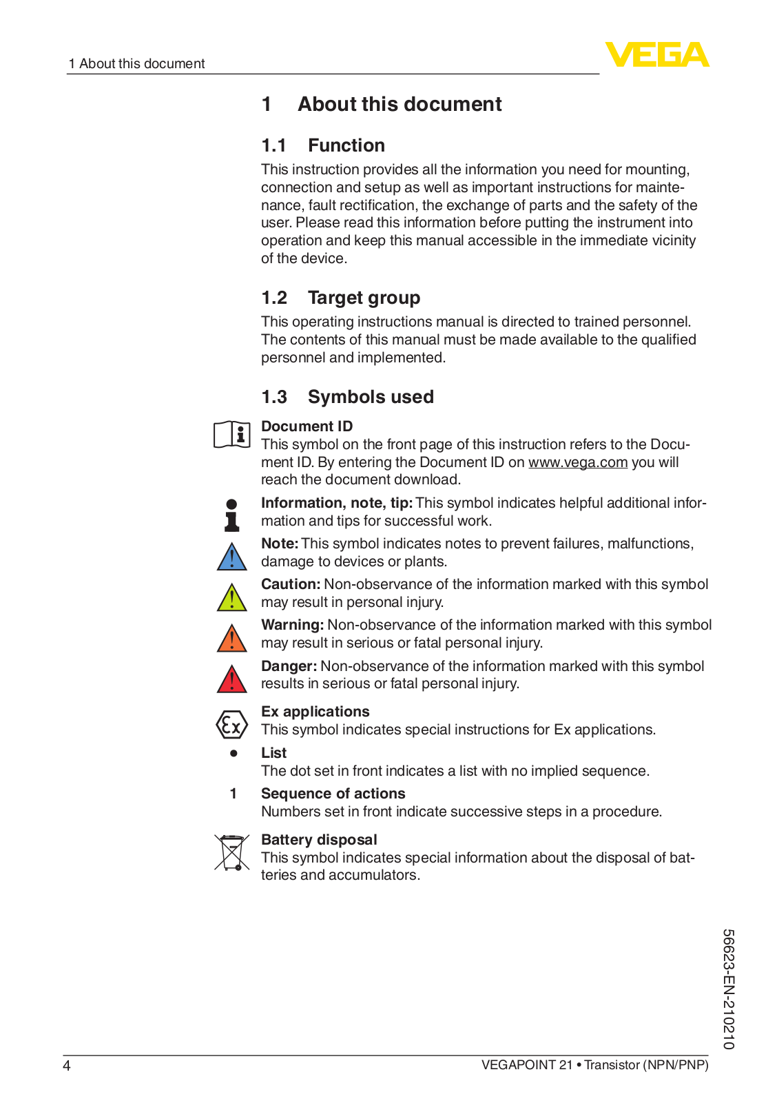
Document ID

This symbol on the front page of this instruction refers to the Document ID. By entering the Document ID on www.vega.com you will reach the document download.

Information, note, tip: This symbol indicates helpful additional information and tips for successful work.

Note: This symbol indicates notes to prevent failures, malfunctions, damage to devices or plants.

Caution: Non-observance of the information marked with this symbol may result in personal injury.

Warning: Non-observance of the information marked with this symbol may result in serious or fatal personal injury.

Danger: Non-observance of the information marked with this symbol results in serious or fatal personal injury.

Ex applications

This symbol indicates special instructions for Ex applications.

ListThe dot set in front indicates a list with no implied sequence.

1Sequence of actions

Numbers set in front indicate successive steps in a procedure.

Battery disposal

This symbol indicates special information about the disposal of batteries and accumulators.

<![if ! IE]>

<![endif]>210210-EN-56623

4

VEGAPOINT 21 • Transistor (NPN/PNP)

<![if ! IE]>

<![endif]>56623-EN-210210

2 For your safety

2 For your safety

2.1Authorised personnel

All operations described in this documentation must be carried out only by trained, qualified personnel authorised by the plant operator.

During work on and with the device, the required personal protective equipment must always be worn.

2.2Appropriate use

The VEGAPOINT 21 is a sensor for point level detection.

You can find detailed information about the area of application in chapter " Product description".

Operational reliability is ensured only if the instrument is properly used according to the specifications in the operating instructions manual as well as possible supplementary instructions.

2.3Warning about incorrect use

Inappropriate or incorrect use of this product can give rise to applica- tion-specific hazards, e.g.vessel overfill through incorrect mounting or adjustment. Damage to property and persons or environmental contamination can result. Also, the protective characteristics of the instrument can be impaired.

2.4General safety instructions

This is a state-of-the-art instrument complying with all prevailing regulations and directives. The instrument must only be operated in a technically flawless and reliable condition.The operator is responsible for the trouble-free operation of the instrument. When measuring aggressive or corrosive media that can cause a dangerous situation if the instrument malfunctions, the operator has to implement suitable measures to make sure the instrument is functioning properly.

The safety instructions in this operating instructions manual, the national installation standards as well as the valid safety regulations and accident prevention rules must be observed by the user.

For safety and warranty reasons, any invasive work on the device beyond that described in the operating instructions manual may be carried out only by personnel authorised by the manufacturer. Arbitrary conversions or modifications are explicitly forbidden.For safety reasons, only the accessory specified by the manufacturer must be used.

To avoid any danger, the safety approval markings and safety tips on the device must also be observed.

2.5Installation and operation in the USA and Canada

This information is only valid for USA and Canada. Hence the following text is only available in the English language.

VEGAPOINT 21 • Transistor (NPN/PNP)

5

2 For your safety

Installations in the US shall comply with the relevant requirements of the National Electrical Code (ANSI/NFPA 70).

Installations in Canada shall comply with the relevant requirements of the Canadian Electrical Code

A Class 2 power supply unit has to be used for the installation in the USA and Canada.

2.6Safety instructions for Ex areas

For Ex applications, only devices with corresponding Ex approval may be used.Observe the Ex-specific safety instructions.These are an integral part of the operating instructions and are enclosed with every device with Ex approval.

<![if ! IE]>

<![endif]>210210-EN-56623

6

VEGAPOINT 21 • Transistor (NPN/PNP)

3 Product description


3

Product description


3.1 Configuration

Scope of delivery


The scope of delivery encompasses:


VEGAPOINT 21 point level switch


Information sheet " Documents and software" with:


–– Instrument serial number


–– QR code with link for direct scanning


with:Information sheet " PINs and Codes" (with Bluetooth versions)


–– Bluetooth access code


Note:


Optional instrument features are also described in this operating


instructions manual. The respective scope of delivery results from the


order specification.

Scope of this operating


This operating instructions manual applies to the following instrument

instructions


versions:


Hardware version from 1.0.0


Software version from 1.3.0

Constituent parts


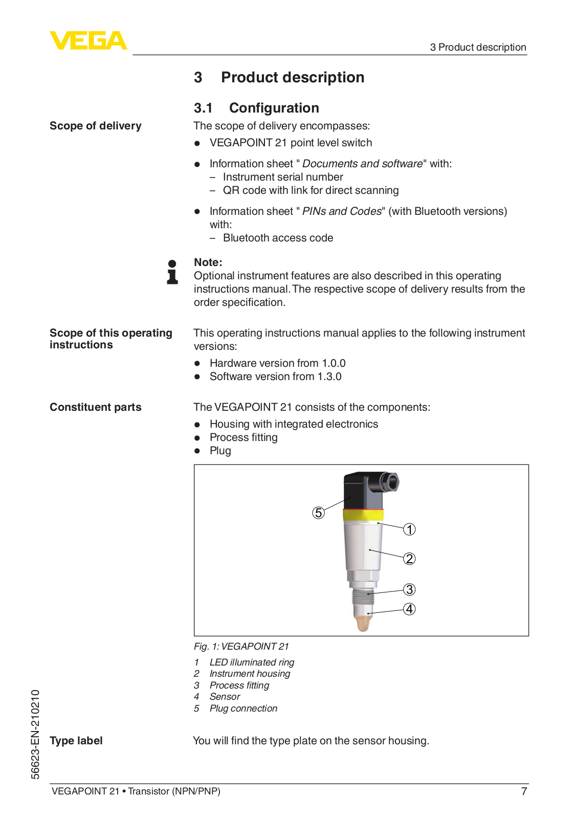
The VEGAPOINT 21 consists of the components:


Housing with integrated electronics


Process fitting


Plug


5


1


2


3


4


<![if ! IE]>

<![endif]>56623-EN-210210


Fig. 1: VEGAPOINT 21


1

LED illuminated ring


2

Instrument housing


3

Process fitting


4

Sensor


5

Plug connection


Type label

You will find the type plate on the sensor housing.


VEGAPOINT 21 • Transistor (NPN/PNP)

7

3 Product description

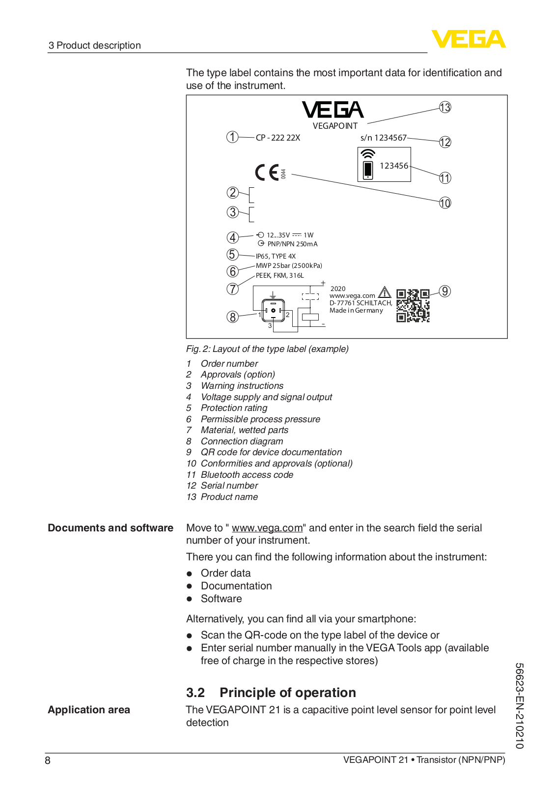
The type label contains the most important data for identification and use of the instrument.


13

1


VEGAPOINT


CP - 222 22X

s/n 1234567

12


<![if ! IE]>

<![endif]>0044

123456

11


2


10

3


4


12...35V

1W


5


PNP/NPN 250mA


IP65, TYPE 4X


6

MWP 25bar (2500kPa)


PEEK, FKM, 316L


7


+ 2020

9


www.vega.com


D-77761 SCHILTACH,


8

1

2

Made in Germany


-


3


Fig. 2: Layout of the type label (example)

1Order number

2Approvals (option)

3Warning instructions

4Voltage supply and signal output

5Protection rating

6Permissible process pressure

7Material, wetted parts

8Connection diagram

9QR code for device documentation

10Conformities and approvals (optional)

11Bluetooth access code

12Serial number

13Product name

Documents and software Move to " www.vega.com" and enter in the search field the serial number of your instrument.

There you can find the following information about the instrument:

Order data

Documentation

Software

Alternatively, you can find all via your smartphone:

Scan the QR-code on the type label of the device or

Enter serial number manually in the VEGA Tools app (available free of charge in the respective stores)

3.2Principle of operation

Application area

The VEGAPOINT 21 is a capacitive point level sensor for point level


detection


8

VEGAPOINT 21 • Transistor (NPN/PNP)

<![if ! IE]>

<![endif]>210210-EN-56623

3 Product description

It is designed for industrial use in all areas of process technology and can be used in water-based liquids.

Typical applications are overfill and dry run protection.With a the small sensor unit, VEGAPOINT 21 can be also mounted e.g. in thin pipelines. The sensor allows use in vessels, tanks and pipes. Thanks to its simple and robust measuring system, VEGAPOINT 21 is virtually unaffected by the chemical and physical properties of the liquid.

It also works under difficult measuring conditions such as turbulence, air bubbles, strong external vibrations or changing media. In addition, the sensor can also detect foam.

Function monitoring

The electronics module of VEGAPOINT 21 continuously monitors the following criteria via frequency generation:


Failure of the signal generation


Line break to the sensor element


If a malfunction is detected or in case of voltage supply, the electron-


ics takes on a defined switching status, i.e.the output is open (safe


state).

Functional principle

An alternating electric field is generated at the tip of the measur-


ing electrode. If the sensor is covered with medium, the resonance


frequency changes. This change is detected by the electronics and


converted into a switching command.


Buildup is ignored to a certain degree and therefore has no influence


on the measurement.


3.3 Adjustment

Local adjustment

The switching status of VEGAPOINT 21 can be checked from outside


(LED illuminated ring).

Wireless adjustment

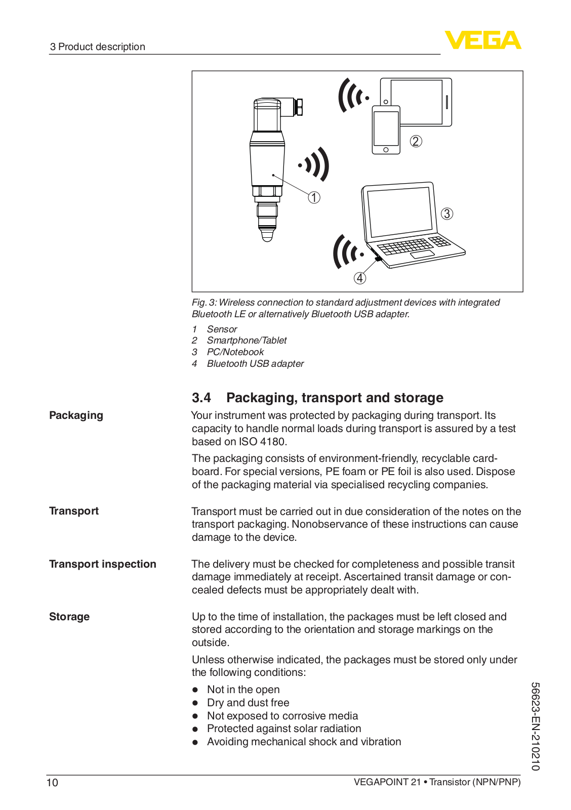
The optionally integrated Bluetooth module enables in addition a wire-


less adjustment of VEGAPOINT 21.


This is done via standard operating devices:


Smartphone/tablet (iOS or Android operating system)


PC/notebook with Bluetooth LE or Bluetooth USB adapter (Win-


dows operating system)

<![if ! IE]>

<![endif]>56623-EN-210210

VEGAPOINT 21 • Transistor (NPN/PNP)

9

3 Product description

2

1

3


4


Fig. 3: Wireless connection to standard adjustment devices with integrated

Bluetooth LE or alternatively Bluetooth USB adapter.

1

Sensor

2

Smartphone/Tablet

3

PC/Notebook

4

Bluetooth USB adapter


3.4 Packaging, transport and storage

Packaging

Your instrument was protected by packaging during transport. Its


capacity to handle normal loads during transport is assured by a test


based on ISO 4180.


The packaging consists of environment-friendly, recyclable card-


board. For special versions, PE foam or PE foil is also used. Dispose


of the packaging material via specialised recycling companies.

Transport

Transport must be carried out in due consideration of the notes on the


transport packaging. Nonobservance of these instructions can cause


damage to the device.

Transport inspection

The delivery must be checked for completeness and possible transit


damage immediately at receipt. Ascertained transit damage or con-


cealed defects must be appropriately dealt with.

Storage

Up to the time of installation, the packages must be left closed and


stored according to the orientation and storage markings on the


outside.


Unless otherwise indicated, the packages must be stored only under


the following conditions:


Not in the open


Dry and dust free


Not exposed to corrosive media


Protected against solar radiation


Avoiding mechanical shock and vibration


10


VEGAPOINT 21 • Transistor (NPN/PNP)

<![if ! IE]>

<![endif]>210210-EN-56623


3 Product description

Storage and transport

Storage and transport temperature see chapter " Supplement -

temperature

Technical data - Ambient conditions"


Relative humidity 20 … 85 %

3.5 Accessories

Threaded and hygienic socket

The instructions for the listed accessories can be found in the download area on our homepage.

Various threaded and hygienic sockets are available for devices with threaded version.

You can find further information in the "Technical data"

<![if ! IE]>

<![endif]>56623-EN-210210

VEGAPOINT 21 • Transistor (NPN/PNP)

11

4 Mounting

4 Mounting

Ambient conditions

Process conditions

Switching point

4.1General instructions

The instrument is suitable for standard and extended ambient conditions acc. to DIN/EN/IEC/ANSI/ISA/UL/CSA 61010-1. It can be used indoors as well as outdoors.

Note:

For safety reasons, the instrument must only be operated within the permissible process conditions.You can find detailed information on the process conditions in chapter " Technical data" of the operating instructions or on the type label.

Hence make sure before mounting that all parts of the instrument exposed to the process are suitable for the existing process conditions.

These are mainly:

Active measuring component

Process fitting

Process seal

Process conditions in particular are:

Process pressure

Process temperature

Chemical properties of the medium

Abrasion and mechanical influences

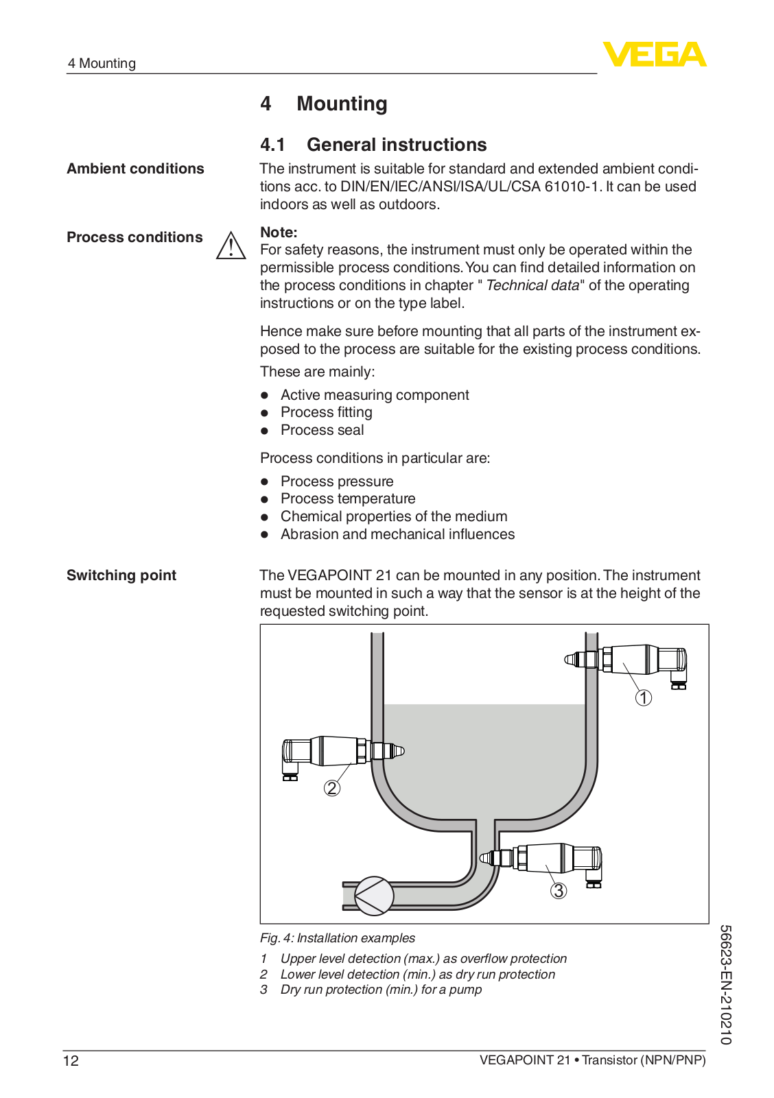
The VEGAPOINT 21 can be mounted in any position. The instrument must be mounted in such a way that the sensor is at the height of the requested switching point.

1

2

Fig. 4: Installation examples

1 Upper level detection (max.) as overflow protection

2Lower level detection (min.) as dry run protection

3Dry run protection (min.) for a pump

12

VEGAPOINT 21 • Transistor (NPN/PNP)

<![if ! IE]>

<![endif]>210210-EN-56623

4 Mounting

Note that the switching point varies depending on the type of medium and the mounting position of the sensor.

Protection against mois- Protect your instrument against moisture ingress through the following

ture

measures:


Use a suitable connection cable (see chapter " Connecting to


power supply")


Tighten the cable gland or plug connector


Lead the connection cable downward in front of the cable entry or


plug connector


This applies mainly to outdoor installations, in areas where high


humidity is expected (e.g. through cleaning processes) and on cooled


or heated vessels.

Handling

The level switch is a measuring device for stationary screw mounting


and must be treated accordingly. Damage to the measuring tip will


destroy the instrument.


Use the hexagon above the thread for screwing in.


After mounting, make sure that the process fitting is screwed in cor-


rectly and thus securely seals even at maximum process pressure.


4.2 Mounting instructions

Adhesive products

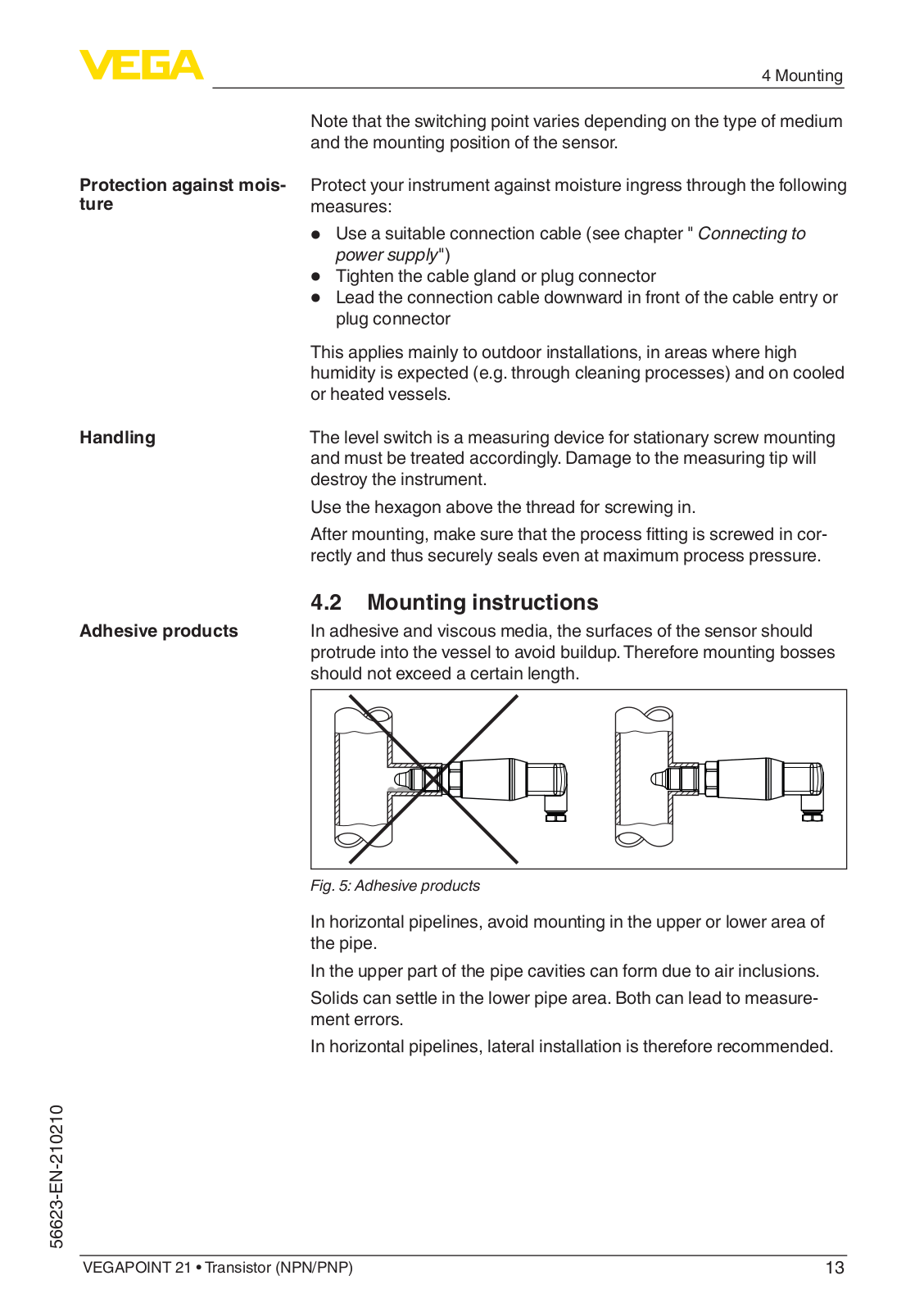
In adhesive and viscous media, the surfaces of the sensor should


protrude into the vessel to avoid buildup. Therefore mounting bosses


should not exceed a certain length.


Fig. 5: Adhesive products

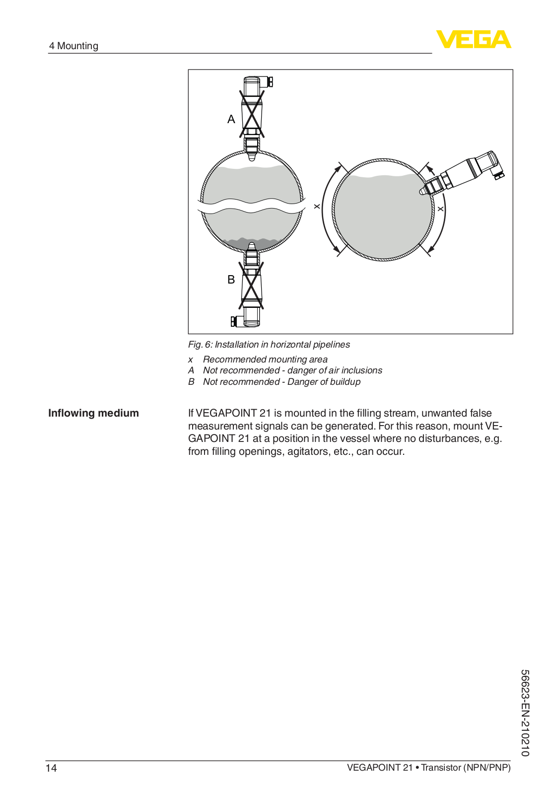
In horizontal pipelines, avoid mounting in the upper or lower area of the pipe.

In the upper part of the pipe cavities can form due to air inclusions.

Solids can settle in the lower pipe area. Both can lead to measurement errors.

In horizontal pipelines, lateral installation is therefore recommended.

<![if ! IE]>

<![endif]>56623-EN-210210

VEGAPOINT 21 • Transistor (NPN/PNP)

13

VEGA VEGAPOINT 21 Operating Instructions

4 Mounting

A

<![if ! IE]>

<![endif]>x

B

Fig. 6: Installation in horizontal pipelines x Recommended mounting area

ANot recommended - danger of air inclusions

BNot recommended - Danger of buildup

Inflowing medium

IfVEGAPOINT 21 is mounted in the filling stream, unwanted false


measurement signals can be generated. For this reason, mount VE-


GAPOINT 21 at a position in the vessel where no disturbances, e.g.


from filling openings, agitators, etc., can occur.

<![if ! IE]>

<![endif]>210210-EN-56623

14

VEGAPOINT 21 • Transistor (NPN/PNP)


5 Connecting to power supply


5

Connecting to power supply


5.1 Preparing the connection

Safety instructions

Always keep in mind the following safety instructions:


Carry out electrical connection by trained, qualified personnel


authorised by the plant operator


If overvoltage surges are expected, overvoltage arresters should


be installed


Warning:


Only connect or disconnect in de-energized state.

Voltage supply

The data for power supply are specified in chapter " Technical data".


Note:


Power the instrument via an energy-limited circuit (power max. 100 W)


acc. to IEC 61010-1, e.g.


Class 2 power supply unit (acc. to UL1310)


SELV power supply unit (safety extra-low voltage) with suitable


internal or external limitation of the output current


Keep in mind the following additional factors that influence the operat-


ing voltage:


Lower output voltage of the power supply unit under nominal load


Influence of additional instruments in the circuit (see load values in


chapter " Technical data")

Connection cable

Use cable with round cross section. Depending on the plug connec-


tion, you have to select the outer diameter of the cable respectively so


that the seal effect of the cable gland is ensured.

The instrument is connected with standard four-wire cable. If electromagnetic interference is expected which is above the test values of EN 61326-1 for industrial areas, shielded cable should be used.

Valve plug ISO 4400, ø 4.5 … 7 mm

Valve plug ISO 4400 with IDC crimping technology, ø 5.5 … 8 mm

Valve plug ISO 4400 with hinged cover, ø 4,5 … 7 mm

<![if ! IE]>

<![endif]>56623-EN-210210

VEGAPOINT 21 • Transistor (NPN/PNP)

15

Loading...
+ 33 hidden pages