

Page 1
Operating Instructions
VEGADIF 34 … 51
Level and Pressure
p
Page 2

Contents
Safety information ......................................................................... 3
Note Ex-area ................................................................................ 3
1 Product description
1.1 Function and configuration ................................................... 4
1.2 Types and versions .............................................................. 5
1.3 Type plate ............................................................................. 7
1.4 Technical data ....................................................................... 8
1.5 Dimensions ......................................................................... 15
1.6 Approvals ........................................................................... 20
2 Mounting
2.1 Verifying operating conditions ........................................... 21
2.2 Pre-installation ..................................................................... 22
2.3 Mounting .............................................................................. 24
3 Electrical connection
3.1 Connection instructions ...................................................... 28
3.2 Load resistance .................................................................. 28
3.3 Connections ........................................................................ 29
3.4 Ex-applications ................................................................... 30
Contents
4 Setup
4.1 Adjustment structure .......................................................... 32
4.2 Adjustment with 4-key adjustment element ....................... 32
4.3 Adjustment with HART® handheld ...................................... 38
4.4 Adjustment with PC ............................................................ 46
2 VEGADIF 34 … 51
Page 3

Contents
5 Typical installation connections
5.1 Valves .................................................................................. 53
5.2 Impulse lines ....................................................................... 54
5.3 Differential pressure measurement ................................... 55
5.4 Level measurement ............................................................ 57
5.5 Flow measurement ............................................................. 65
6 Diagnostics
6.1 Failure codes ...................................................................... 69
7 Instrument modification ......................................................... 70
Safety information
The described module must only be installed
and operated as described in these operating
instructions. Please note that other action can
cause damage for which VEGA does not take
responsibility.
VEGADIF 34 … 51 3
Note Ex-area
Please note the approval documents (yellow
binder), and especially the included safety data
sheet.
Page 4

1 Product description
Product description
1.1 Function and configuration
Function
VEGADIF 34 … 51 differential pressure transmitters are an efficient, modular instrument
series for differential pressure, level and flow
measurement.
The sensor element of VEGADIF 34 and 44 is
a single-chamber ceramic measuring cell. It
consists of a disk-shaped ceramic body with
ceramic diaphragms on both sides. According to the pressure the diaphragms move and
the capacitances change. The difference of
the individual capacitances is reciprocally
proportional to the difference of the pressures.
The sensor element of VEGADIF 35, 45 and 51
is a silicium plate with pressure sensitive resistors. The differential pressure to be measured is received via separating diaphragms
and transmitted to the sensor element via
incompressible oil (silicone oil or inert oil). The
silicium plate moves according to the differential pressure. The values of the resistors
change (piezoresistive principle).
The capacitance or resistance values are
detected by the integral electronics and converted into a 4 … 20 mA output signal. This
output signal is proportional to the difference
of the pressures. Precise digital processing of
measured data with maximum resolution ensures excellent technical performance.
The external power supply is provided via a
separate supply instrument, e.g.:
- power supply instrument
(e.g. VEGASTAB 690)
- processing unit with integral direct voltage
source (e.g. active DCS-input)
- VEGAMET series 500 or 600 signal conditioning instrument, VEGALOG 571 processing system or VEGADIS 371 indicating
instrument
Configuration
Each VEGADIF consists of only two modular
components:
- the electronics housing
- the measuring cell housing.
Sensor specific data are permanently stored
in an ASIC in the sensor. Hence the measuring
cell modules can be changed, e.g. ceramic for
silicium and vice versa. The electronics can be
changed, e.g. from 4 … 20 mA standard to
4 … 20 mA with HART®-communication protocol, without dismounting the transmitter.
The electronics in the pressure transmitter
requires a supply voltage of 11.5 … 45 V DC.
4 VEGADIF 34 … 51
Page 5
Product description
1.2 T ypes and versions
VEGADIF 34
Measuring cell:
ceramic-capacitive
Process connection:
acc. to DIN 19 213
Standard application:
Differential pressure and flow measurement
with gases, vapours and liquids
VEGADIF 35
Measuring cell:
silicium-piezoresistive with metal separating
diaphragms
Process connection:
acc. to DIN 19 213
VEGADIF 34
Standard application:
Differential pressure and flow measurement
with gases, vapours and liquids, with differential pressure up to 40 bar and static pressures up to 420 bar
VEGADIF 35
VEGADIF 44
Measuring cell:
ceramic-capacitive
Process connection:
Plus side flange,
minus side acc. to DIN 19 213
Standard application:
Level measurement in pressurized vessels,
even with suspended solids, abrasive or high
viscosity products
VEGADIF 34 … 51 5
VEGADIF 44
Page 6
VEGADIF 45
Measuring cell:
silicium-piezoresistive with metal separating
diaphragm
Process connection:
Plus side flange,
minus side acc. to DIN 19 213
Standard application:
Level measurement in pressurized vessels,
even with product temperatures up to 400°C
VEGADIF 51
Measuring cell:
silicium-piezoresistive with metal separating
diaphragms
Product description
VEGADIF 45
Process connection:
Cell isolating diaphragm in standard series,
connected via capillary lines
Standard application:
Level, differential pressure and flow measurement especially with high-viscosity products,
high temperatures and in food processing
industries
For applications in hazardous areas as well as
overfill protection acc. to WHG certified instruments are available
6 VEGADIF 34 … 51
VEGADIF 51
Page 7
Product description
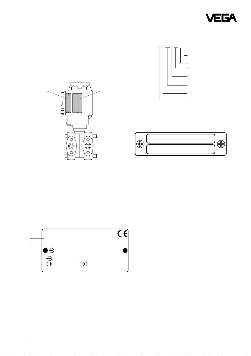
1.3 T ype plate
Check before mounting and electrical connection that you are using a suitable differential
pressure transmitter. Observe type and calibration plate which are located as follows:
Calibration plate
Both plates include important data required for
mounting and connection. The configuration
and contents of the plates are explained in the
following example.
Type plate
Product coding example
type DIF35AC4E1VH3C
Process connection flange
1.4435
Measuring cell seal PTFE
2 ventilation valves,
1 mounting loop
Nominal value calibration
in mbar/bar
Nom. meas. range 160 mbar,
static pressure max. 140 bar
LC-indication top
Cable entry Pg 13.5
Configuration of the calibration plate
(example)
Cal.
Adj. 0 … 160 MBAR
Calibration range 0 … 160 mbar
Configuration of the type plate (example)
1
2
Order Code
Ser.-No.
p
Pmax
4…20mA U
Mat.
1 Basic data of the order no.
2 Serial number
VEGADIF 34 … 51 7
DIF35 AC4E1 VH 3C
10612892
-160 … 160 mbar
140 bar
1.4571 PTFE
VEGA VEGADIF
Made in
Germany
11,5 … 45 V DC
Page 8

Product description
1.4 T echnical data
Mechanical data
Materials, wetted parts
VEGADIF 34
- Diaphragm Aluminiumoxideceramic (Al2O3)
- Process seal FPM, Hastelloy C4 PTFE-plated, EPDM,
- Process connection carbon steel C22.8 chromized 1.0460,
- Ventilation valves stainless steel 1.4571 or 1.4404, Hastelloy C276
VEGADIF 35
- Separating diaphragms stainless steel 1.4401
- Process seal FPM, NBR, PTFE, FPM for oxygen
- Process connection carbon steel C22.8 chromized 1.0460
- Ventilation valves stainless steel 1.4571 or 1.4404, Hastelloy C276
VEGADIF 44
- Diaphragm Aluminiumoxideceramic (Al2O3)
- Process seal FPM, Hastelloy C-4 PTFE-plated, EPDM,
- Process connection (plus side) carbon steel C22.8 chromized 1.0460,
- Process connection (minus side) carbon steel C22.8 chromized 1.0460,
FPM for oxygen application, Kalrez
stainless steel 1.4571 or 1.4404, Hastelloy C276
2.4819, PVDF (PN 10)
2.4819 (only with process connection Hastelloy)
applications
stainless steel 1.4571 or 1.4404, Hastelloy C276
2.4819
2.4819 (only with process connection Hastelloy)
FPM for oxygen application, Kalrez
stainless steel 1.4571, stainless steel 1.4571
PTFE coated
Hastelloy C276 2.4819
stainless steel 1.4571 or 1.4404, Hastelloy C276
2.4819
VEGADIF 45
- Isolating diaphragm stainless steel 1.4435
- Process flange (plus side) stainless steel 1.4435
- Process flange (minus side) carbon steel C22.8 chromized 1.0460,
VEGADIF 51
- Isolating diaphragm stainless steel 1.4435
- Process connection carbon steel C22.8 chromized 1.0460,
8 VEGADIF 34 … 51
stainless steel 1.4571 or 1.4404, Hastelloy C276
2.4819
stainless steel 1.4571 or 1.4404, Hastelloy C276
2.4819
Page 9

Product description
Materials, non-wetted parts
Common components
- Electronics housing and cover Al-casting (Cu-free), protective coating
Polyester based, colour yellow RAL 1018,
black RAL … (cover)
- Type plates stainless steel 1.4301
- O-rings for cover seal NBR
- Screws and nuts
for measuring cell housing or
process connection carbon steel C22.8
- Mounting loop corresponding to process connection
carbon steel C22.8, stainless steel 1.4571
1)
VEGADIF 34
- Fill fluid of the measuring cell silicone oil, mineral oil, Voltalef 1 A
VEGADIF 35
- Measuring cell housing stainless steel 1.4571
- Fill fluid of the measuring cell silicone oil, Fluorlube
2)
VEGADIF 44
- Fill fluid of the measuring cell silicone oil, mineral oil, Voltalef 1 A
VEGADIF 45 and VEGADIF 51
- Measuring cell housing stainless steel 1.4571
- Fill fluid of the measuring cell silicone oil, vegetable oil, glycerine, high
temperature oil, oil for oxygen applications
- Capillary line stainless steel 1.4571
- Fill fluid of the measuring cell silicone oil, Fluorlube
2)
Weights
VEGADIF 34 approx. 5 kg
VEGADIF 35 4 … 6 kg, depending on version
VEGADIF 44 8 … 10.5 kg, depending on flange size
VEGADIF 45 6 … 12 kg, depending on flange size and
extension length
VEGADIF 51 4 kg plus capillaries and flange isolating
diaphragm
Isolating diaphragm see tables in "1.5 Dimensions - Isolating
diaphragm"
2)
2)
1)
Sea water resistance (salt spray test acc. to DIN 50 021 passed for 504 h)
2)
for applications in pure gases
VEGADIF 34 … 51 9
Page 10
Electrical data
Product description
Connection
Cable entry Pg 13.5 (for cable-ø 9 … 12 mm)
1)
Screw terminals for conductor cross-sections up to 2.5 mm
Earth terminal for conductor cross-sections up to 4 mm
Supply and signal circuit (4 … 20 mA-signal)
Supply voltage
- not Ex-instruments 11.5 … 45 V DC
- Ex-instruments 11.5 … 30 V DC
Residual ripple no influence at USS £ 4.5 V
Output signal 4 … 20 mA linear (differential pressure proportio
nal) or square root (flow proportional changeable)
Resolution better than 6 µA
Current limitation approx. 23 mA
Measuring range decrease 2.8 mA (standard) or 4 mA
Measuring range exceed 20.5 mA acc. to NAMUR
Fault signal (adjustable) 3.6 mA, 21.5 mA, current value
Integration time
2)
0 … 16 s with keys on the instrument
0 … 40 s with HART® handheld
Adjustment period 0.5 … 2.0 s depending on measuring range
Raising time 0.4 … 1.6 s depending on measuring range
Heating time 2 s
Connection line 2-wire
Max. permissible load depending on supply voltage
1560
1000
in Ohm
R total
500
Load
0
20 28,5 37 4511,5
Voltage of the external energy UH in Volts
Supply and signal circuit (digital communication signal HART®)
Connection line 2-wire (the communication must not be influenced
by unshielded cables)
Line resistance £ 25 W/km
Total resistance higher than 250 W (communication resistance of
min. 250 W required)
Total capacitance smaller than 180 nF
Max. length 1000 m
2
2
1)
with smaller cable diameter a suitable seal must be provided by the customer
2)
adjustment time of 10 % … 63 % of the measuring range final value
10 VEGADIF 34 … 51
Page 11
Product description
Protective measures
Protection IP 65
IP 68 (option for VEGADIF 35, 45 and 51)
Protection class III
CE-protective measures
VEGADIF 34, VEGADIF 35, VEGADIF 44, VEGADIF 45 and VEGADIF 51 differential pressure
transmitters meet the protective regulations of EMC (89/336/EWG) and NSR (73/23/EWG).
The conformity has been judged acc. to the following standards:
EMC Emission EN 50 081 - 1
Susceptibility EN 50 082 - 2
NSR EN 61 010
NAMUR-regulations
Full compliance with the NAMUR-regulations NE21, May 1993.
Transmission reaction
Measuring ranges
VEGADIF 34 and VEGADIF 44
Features Limits Span System pressure Pressure transmission
Nom. liquid
meas. Initial Final value minimum maximum Overload Overload in the sensor
ranges value unilateral bilateral
25 mbar -25 mbar 25 mbar 5 mbar 25 mbar 10 bar 10 bar silicone oil
100 mbar -100 mbar 100 mbar 5 mbar 100 mbar 16 bar 2)25 bar 2)silicone oil
500 mbar -500 mbar 500 mbar 25 mbar 500 mbar 100 bar 2)140 bar 2)mineral oil
3000 mbar -3000 mbar 3000 mbar 150 mbar 3000 mbar 100 bar 2)140 bar 2)mineral oil
1)
1)
1)
1)
VEGADIF 35, VEGADIF 45 and VEGADIF 51
Features Limits Span System pressure Pressure transmission
Nom. liquid
meas. Initial Final value minimum maximum Overload Overload in the sensor
ranges value unilateral bilateral
3)
10 mbar
40 mbar
160 mbar -160 mbar 160 mbar 10 mbar 160 mbar 140 bar 140 bar silicone oil
1000 mbar -1000 mbar 1000 mbar 50 mbar 1000 mbar 420 bar 4)420 bar 4)silicone oil
6000 mbar -6000 mbar 6000 mbar 300 mbar 6000 mbar 420 bar 4)420 bar 4)silicone oil
40000 mbar3)-40000 mbar 40000 mbar 2000 mbar 40000 mbar 100 bar 420 bar 4)silicone oil
-10 mbar 10 mbar 2 mbar 10 mbar 140 bar 140 bar s ilicone oil
3)
-40 mbar 40 mbar 5 mbar 40 mbar 140 bar 140 bar s ilicone oil
1)
1)
1)
1)
1)
1)
Minimum pressure
VEGADIF 34, 35 and 44 1 mbar
VEGADIF 45 and 51 10 mbar
1)
in applications with pure gases Voltalef 1 A
2)
10 bar with process connection PVDF for VEGADIF 34; 40 bar with process flange for VEGADIF 44
3)
only VEGADIF 35
4)
note nominal pressure of the flanges
VEGADIF 34 … 51 11
abs
abs
Page 12

Product description
Output characteristics
Determination of characteristics fixed point method acc. to VDI/VDE 2600, sheet 4
(corresponds to the limit point adjustment acc. to
DIN 16 086)
Characteristics linear (differential pressure proportional),
changeable to square root (flow proportional)
Accuracy data
1)
Feature Accuracy
2)
Hysteresis Repeatability
Instrument
VEGADIF 34 better than 0.1 % better than 0.05 % better than 0.05 %
VEGADIF 35 better than 0.1 % better than 0.1 % better than 0.1 %
VEGADIF 44 better than 0.1 % better than 0.05 % better than 0.05 %
VEGADIF 45 better than 0.2 % better than 0.1 % better than 0.1 %
VEGADIF 51 better than 0.2 % better than 0.1 % better than 0.1 %
Long-term stability of the zero signal
3)
better than 0.1%/12 months (VEGADIF 34 and 44)
better than 0.2%/12 months (VEGADIF 35, 45, 51)
Influence of other actuating variables
Influence of the static pressure
to zero and span better than 0.2 %/PN (VEGADIF 34 and 44)
better than 0.2 %/100 bar (VEGADIF 35, 45, 51)
Electromagnetic compatibility (EMC) interference immunity to NAMUR: 30 V/m
Influence of vibration
5) 6)
better than ±0.1 % acc. to DIN/IEC 68, part 2 - 6
Climatic class GPC acc. to DIN 40 040
Calibration position upright
Influence of the mounting position max. 2 mbar
Temperature influence
Average temperature influence of the
zero signal
3) 4)
or the output span better than 0.02 %/10 K (+10 … +60°C)
better than 0.1 %/10 K (-40 … + 10°C a.
60°C…85°C)
1)
Similar to DIN 16 086
2)
relating to the nominal measuring range with recommended turn-down limit of 20 : 1
3)
relating to the nominal measuring range, reference temperature 25°C, with recommended turn-down limit of
20 : 1
4)
with VEGADIF 45 and 51 without isolating diaphragm or capillaries, see temperature influence
5)
relating to the nominal measuring range
6)
with silicium measuring cell measured on 6000 mbar sensor
12 VEGADIF 34 … 51
Page 13
Product description
Additional temperature influence 1) with VEGADIF 45:
- by isolating diaphragm
Process connection effective Temperature coefficient
diaphragm-ø [mbar/10 K]
Flange DN 50 PN 40 acc. to DIN 2501,
Seal surface acc. to DIN 2526 form D 46 mm 5.0
Flange DN 80 PN 40 acc. to DIN 2501,
Seal surface acc. to DIN 2526 form D 70 mm 3.0
Flange DN 80 PN 40 with extension 50 mm 70 mm 3.0
Flange DN 80 PN 40 with extension 100 mm 70 mm 3.0
Flange DN 80 PN 40 with extension 150 mm 70 mm 3.0
Flange DN 80 PN 40 with extension 200 mm 70 mm 3.0
Additional temperature influence
1)
with VEGADIF 45:
- by isolating diaphragm
Isolating diaphragm series effective Temperature coefficient
diaphragm-ø [mbar/10 K]
unilateral bilateral
Cell DN 50 PN 16/400 46 mm 3.0 0.5
Cell DN 80 PN 16/400 70 mm 0.7 0.1
Cell DN 100 PN 16/400 70 mm 0.7 0.1
Cell 3" class 150/2000 2
3
/4" 0.7 0.1
Cell 4" class 150/2000 23/4" 0.7 0.1
DIN 11 851, nut DN 50 PN 25 46 mm 3.0 0.5
DIN 11 851, nut DN 65 PN 25 52 mm 1.0 0.2
DIN 11 851, nut DN 80 PN 25 71.5 mm 0.7 0.1
DIN 11 851, socket DN 50 PN 25 46 mm 3.0 0.5
DIN 11 851, socket DN 65 PN 25 52 mm 1.0 0.2
DIN 11 851, socket DN 80 PN 25 71.5 mm 0.7 0.1
Clamp 2" PN 25 45 mm 3.0 0.5
Clamp 3" PN 25 71.5 mm 0.7 0.1
DRD-flange DN 25 46 mm 1 .5 0.25
- by capillary line 2) per m 0.5 mbar/10 K (unilateral)
0.12 mbar/10 K (bilateral)
Operating conditions
Product features
Aggregate gaseous, vapour, liquid to high viscosity
Condition also abrasive or aggressive with suitable
1)
standard values relating to isolating liquid silicone oil
2)
both capillary lines are supplied with the same length
VEGADIF 34 … 51 13
material selection of wetted parts acc. to
order code
Page 14

Product description
Temperatures
Ambient temperature -40°C … +85°C (for indication: -20°C … +85°C)
Medium temperature
- VEGADIF 34 and VEGADIF 44
FPM (Viton, Fluor-caoutchouc) -20°C … +85°C
PTFE (Hastelloy C4, from p
EPDM -40°C … +85°C
³ 900 mbar) -40°C … +85°C
abs
FPM (Viton for oxygen, oil and grease free) -10°C … +85°C
Kalrez -10°C … +85°C
- VEGADIF 35 and minus side VEGADIF 45
FDM (Viton, Fluor-caoutchouc) -20°C … +85°C
NBR -20°C … +85°C
PTFE, from p
FPM (Viton for oxygen, oil and grease free) -10°C … +85°C
³ 1 mbar -40°C … +85°C
abs
- Plus side VEGADIF 45 and VEGADIF 51
Isolating liquid: p
- silicone oil -40°C … +200°C / -40°C … +180°C
³ 1 bar / 0.05 bar £ p
abs
- vegetable oil -10°C … +200°C / -10°C … +120°C
- glycerine +15°C … +200°C / – ––
- high temperature oil -10°C … +350°C / -10°C … +200°C
- oil for oxygen application -40°C … +175°C / -40°C … +80°C
Storage and transport temperature -40°C … +100°C (VEGADIF 34 and 44)
-50°C … +100°C (VEGADIF 35, 45 and 51)
Ex-technical data CENELEC
General data
Classification mark EEx ia IIC T4/T6
Intrinsically safe supply and signal circuit
Classification EEx ia IIC
Only for connection to certified, intrinsically
safe circuits with the max. values:
- voltage UO = 30 V
- current IK = 300 mA
- efficiency P = 1 W
Inner effective capacitance C
Inner effective inductance L
Ambient conditions
Ambient temperature around the
oscillator
- temperature class T6 -40°C … +40°C
- temperature class T5 -40°C … +55°C
- temperature class T4 -40°C … +85°C
= 11.2 nF
int
= 0.2 mH
int
1)
abs
< 1 bar
1)
at p
< 1 bar (vacuum range) the isolating liquid boils already at lower temperatures
abs
14 VEGADIF 34 … 51
Page 15
Product description
0-500 mbar
2 5 0
39
Z S
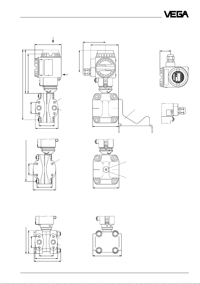
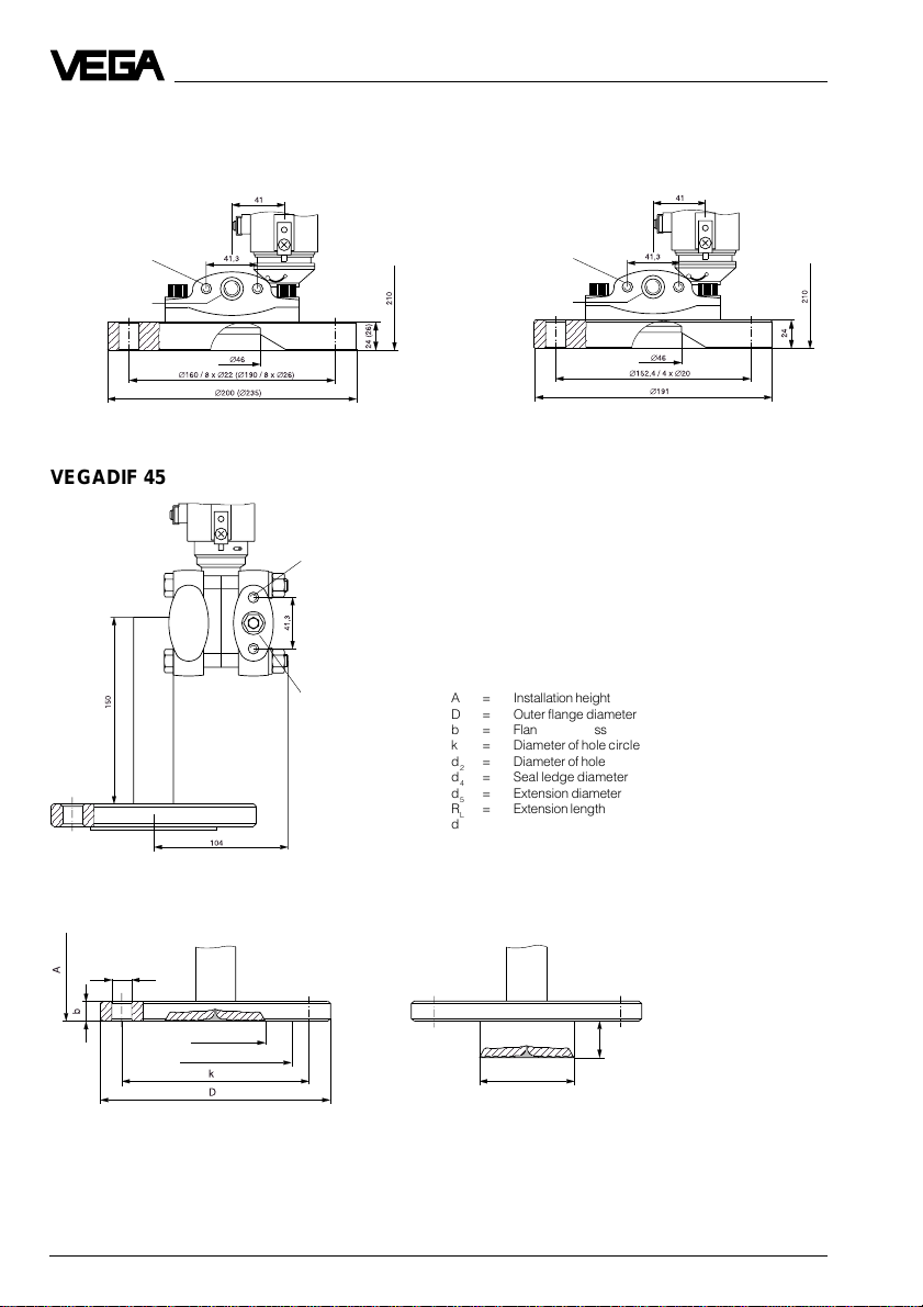
1.5 Dimensions
VEGADIF 34
104
x
81
104
80
View x
150
136
255
41,3
255
41,3
with PVDF-flange
VEGADIF 35
y
M10
7
/16 - 20 UNF
1
/4" - 18 NPT
54
82
M10
7
/16 - 20 UNF
54
82
96
96
Mounting loop
(optional)
PVDF
1
/4" - 18 NPT
View y
235
41,3
85 (93)
54
85
100 (135)
The values in brackets relate to PN 420
VEGADIF 34 … 51 15
M10 (M12)
7
/16 - 20 UNF
1
/4" - 18 NPT
106 (110)
Page 16
VEGADIF 44
;
;;;;;;;
DIN-flange DN 80/DN 100 ANSI-flange 3"
Product description
M10
7
/16 - 20 UNF
1
/4" - 18 NPT
VEGADIF 45
M10
7
/16 - 20 UNF
1
/4" - 18 NPT
M10
7
/16 - 20 UNF
1
/4" - 18 NPT
A = Installation height
D = Outer flange diameter
b = Flange thickness
k = Diameter of hole circle
d2= Diameter of hole
d4= Seal ledge diameter
d5= Extension diameter
RL= Extension length
dM= Diaphragm diameter
d
2
d
M
d
4
d
5
L
R
16 VEGADIF 34 … 51
Page 17
Product description
Flange connection acc. to DIN 2501, seal ledge acc. to DIN 2526 form D
Order Flange Holes Seal ledge Dia. Extension Install.
code Size/Nominal pressure D b k No. d2d
dMR
4
d5dMheight A
L
B DN 50 / PN 40 165 20 125 4 18 102 46 –– –– –– 360
C DN 80 / PN 40 200 24 160 8 22 138 70 –– –– – – 360
D DN 80 / PN 40 200 24 160 8 22 138 –– 50 76.5 70 360
E DN 80 / PN 40 200 24 160 8 22 138 –– 100 76.5 70 360
F DN 80 / PN 40 200 24 160 8 22 138 –– 200 76.5 70 360
G DN 100 / PN 40 235 26 190 8 26 162 70 –– 76.5 70 360
Flange connection acc. to ANSI B 16.5
Order Flange Holes Seal ledge Dia. Extension Install.
code Size/Nominal press. D b k No. d
in lb/sq in in/mm in/mm in/mm in/mm in/mm in/mm in/mm in/mm in/mm A
3
P 2 / 150 6/152
/4 /43/4/43/4/35/8/13/4/ –– –– –– 14.2/
19.5 120.7 20 92 46 360
15
R 3 / 150 8.25/
/16 /6/ 43/4/5 /23/4/ –– –– –– 14.2/
191 24 152.4 20 127 70 360
15
S 3 / 150 8.25/
/16 /6/ 43/4/5/–– 2/ 3/23/4/ 14.2/
191 24 152.4 20 127 50.8 76.5 70 360
15
T 3 / 150 8.25/
/16 /6/ 43/4/5/–– 4/ 3/23/4/ 14.2/
191 24 152.4 20 127 101.6 76.5 70 360
15
U 3 / 150 8.25/
/16 /6/ 43/4/5/–– 8/ 3/23/4/ 14.2/
191 24 152.4 20 127 203.2 76.5 70 360
1
W 4 / 300 10/ 1
/2 /78/9/814/16/62/9/23/4/ –– –– –– 14.2/
254 32 200.1 23 158 70 360
d4d
2
R
M
d5d
L
height
M
VEGADIF 34 … 51 17
Page 18
;
;;;;;;;
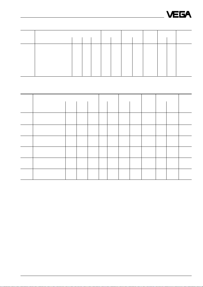
VEGADIF 51
;
7
/16 - 20 UNF
1
/4" -
18 NPT
Isolating diaphragm as cell version, AA … CR
Product description
d
M
acc. to DIN 2501
Order Socket Cell Min. mounting Max. Weight
code Size/Nominal pressure D b d
distance A pressure approx.
M
AA DN 50 PN 16 102 20 46 130 400 bar 2.6 kg
AK DN 80 PN 16 138 20 70 130 400 bar 4.6 kg
AM DN 80 PN 16 PTFE 138 20 70 130 400 bar 4.6 kg
AN DN 80 PN 16 Hastelloy 138 20 70 130 400 bar 4.6 kg
AR DN 100 PN 16 158 20 70 130 400 bar 6.2 kg
acc. to ANSI 16.5
Order Socket Cell Min. mounting Max. Weight
code Size/Nom. pr. D b d
in / lb sq in in/mm in/mm in/mm A in/mm lb/sq in
M
CK 3 / 150 71/2 / 1343/4 / 20 23/4 / 70 5 / 130 –– 4.5 kg
CR 4 / 150 81/4 / 1583/4 / 20 23/4 / 70 5 / 130 2500 6.2 kg
18 VEGADIF 34 … 51
distance pressure approx.
Page 19
Product description
;;;;;;;;;;
;;;;;;;;;;
;;;;;;;;;;
;;;;;;;;;;
;;;;;;;;;;
;;;;;;;;;;
;;;;;;;;;;
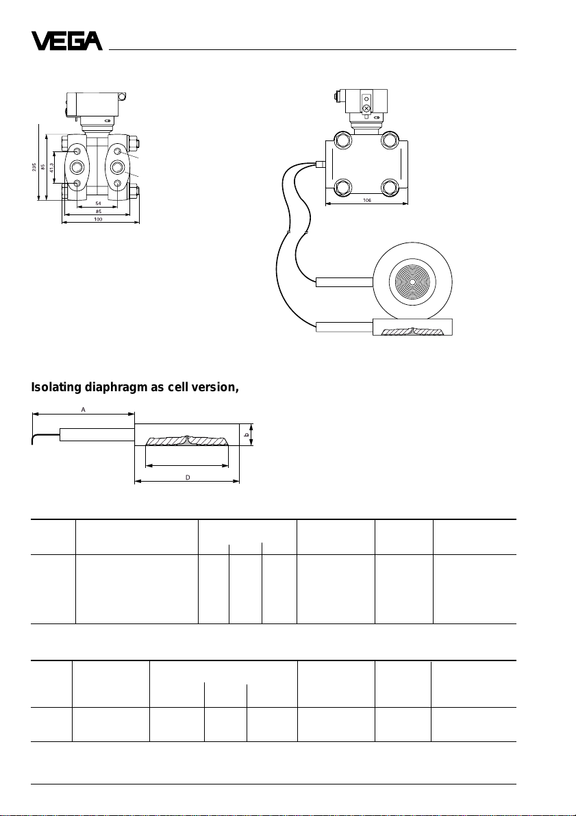
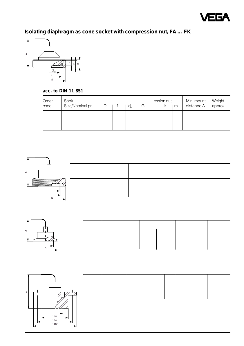
Isolating diaphragm as cone socket with compression nut, FA … FK
d
M
acc. to DIN 11 851
Order Socket Cell Compression nut Min. mount. Weight
code Size/Nominal pr. D f dMG k m distance A approx.
FA DN 50/PN 25 68 11 46 Rd78x
FE DN 65/PN 25 86 12 52 Rd95x1/6" 25 21 120 4.0 kg
FK DN 80/PN 25 100 12 71.5 Rd110x1/4" 29 25 120 5.1 kg
1
/6" 22 19 120 2.2 kg
Isolating diaphragm as threaded socket, GA … GK
acc. to DIN 11 851
Order Socket Threaded socket Min. mounting Weight
code Size/Nominal pres. d1GdMdistance A approx.
d
1
d
M
GA DN 65/PN 25 66 Rd95x1/6" 52 110 3.4 kg
GK DN 80/PN 25 91 Rd110x1/6" 71.5 110 4.0 kg
GA DN 50/PN 25 60 Rd78/
1
/6" 46 110 1.8 kg
Isolating diaphragm as Clamp, HA and HK
Order Socket Terminal socket Min. mounting Weight
code Size/Nominal pres. D d
d
M
HA DN 2" PN 40 64 46 100 1.4 kg
HK DN 3" PN 40 91 71.5 100 2.4 kg
M
distance A approx.
Isolating diaphragm as DRD-flange, KE
Order Socket Dimensions Min. mounting Weight
code Nominal pr. dMdistance A approx.
A
d
M
˘64
˘84
˘105
VEGADIF 34 … 51 19
KE PN 25 see drawing 46 100 1.5 kg
Page 20
Product description
;
;
;
;
;
;
;
;
;
;
;
;
;
;
;
;
;
;
;
;
;
;
;
;
;
;
;
;
;
;
;
105
119
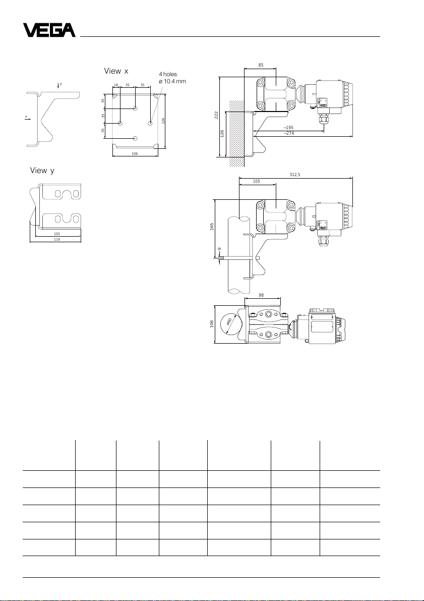
Mounting bracket Installation instructions
;;;;;;
;;;;;;
;;;;;;
;;;;;;
;;;;;;
;;;;;;
;;;;;;
;;;;;;
;;;;;;
;;;;;;
;;;;;;
;;;;;;
;;;;;;
;;;;;;
;;;;;;
;;;;;;
;;;;;;
;;;;;;
;;;;;;
;;;;;;
;;;;;;
;;;;;;
;;;;;;
;;;;;;
;;;;;;
;;;;;;
;;;;;;
;;;;;;
;;;;;;
;;;;;;
;;;;;;
ø60
85
~195
~274
105
312,5
98
x
View y
View x
y
18
35 35
4 holes
ø 10.4 mm
35
35
126
35
222
126
106
165
9
106
+
Z S
-
+
Z S
-
1.6 Approvals
For these applications the appropriate official documents (test reports, test certificates and
conformity certificates) have to be noted. These are supplied with the appropriate instrument.
Survey on the approvals which are in preparation or for which we applied
Approval CENELEC CENELEC PTB-Zone 0 FM FM WHG
Type and non incentive safe
VEGADIF 34 • • • • • •
VEGADIF 35 • • • • • •
VEGADIF 44 • • • • • •
VEGADIF 45 • • • • • •
VEGADIF 51 • • • • • •
20 VEGADIF 34 … 51
EEx ia IIC EEx d IIC EEx ia IIC Explosion proof Intrinsically
Page 21

Mounting
2 Mounting
2.1 Verifying operating conditions
VEGADIF is a rugged transmitter for precise
differential pressure, level and flow measurement. The accuracy of the measurement
mainly depends on the correct installation and
the connection of the impulse lines.
Detailed information for differential pressure
measurement in aggressive products as well
as further information on wiring and coordination of valves, measuring lines and components is given in the VDI/VDE-regulations 3512
as well as DIN 19 201 and DIN 1952. Further
information on level measurement is stated in
the VDI/VDE-regulations 3519.
The differential pressure transmitter used
must meet the technical and safety requirements of the application. Therefore check from
the type plate, calibration plate and order
code the following data:
Nominal pressure
The pressure stage rating of VEGADIF must
be above the operating pressure of the process.
Measuring range
The measuring range is calibrated (factory
set) acc. to the order. The pressure values
adjusted for zero and span are documented
on the calibration plate. The values must cover
the application. If an adaptation is necessary,
this should be carried out acc. to section
4 Setup.
Materials of wetted parts
The material of the wetted parts must be sufficiently resistant. Use the respective material
tables for control. A table is given in the product information to VEGADIF, for more information we recommend the VEGA-resistance lists.
Ambient temperature
The ambient temperature in the installation
place must be in the range of -40°C … +85°C.
The surface temperature of the electronics
housing must not exceed +85°C. Hence it
should be noted that the electronics housing
should not be heated to more than +85°C due
to radiation by neighbouring instruments or
systems. If temperatures below -40°C are
expected at the installation, the transmitter
should be installed in a temperature isolated
and heated protection box. If there is danger
that measured product or condensate freezes
in the process connection or on the measuring
cell, the transmitter must be installed in a
warmer place or in a heated protection box for
process connections and process seals.
Similar measures should be taken to protect
the impulse lines.
Medium temperature
The permissible medium temperature depends on the process seal, the measuring cell
and the isolating liquid. When VEGADIF 45 or
51 are used, note that the product temperature can differ between plus and minus side.
Moisture
Mount horizontally installed instruments such
that the cable entry points to the bottom to
avoid moisture ingress. The sensor housing is
therefore rotational by approx. 350°. For vertically installed instruments loop the connection
lines in a bow pointing to the bottom to the
instrument housing, so that rain or condensation
water can drain off the cable. This is mainly
valid for mounting outside, in humid areas (e.g.
by cleaning processes) or on cooled or heated
vessels.
VEGADIF 34 … 51 21
Page 22
Mounting
2.2 Pre-installation
Selection of the installation location
The selection of a suitable installation location
under extreme ambient conditions is needed
for
- quality of the measurement
- a long lifetime of the transmitter
- low maintenance expenses.
Note the following regulations:
Installation level
• For level measurements install below the
minimum level (the diaphragm or the isolating diaphragm must be completely covered).
• For measurement of gases, install transmit-
ter above the pressure tapping points.
• For the measurement of vapours and liq-
uids, install transmitter below the pressure
tapping points.
Mounting locations
• Mount the transmitter as near as possible to
the pressure tapping points.
• Keep impulse lines as short as possible.
• Mounting and maintenance work should be
carried out without obstruction.
• The transmitter, the tapping points, the
impulse lines and the valves should be
easily accessible.
• If available, the mounting place should provide a good view to the LC-display.
Adaptation of the transmitter
For optimum adaptation of your VEGADIF to
the installation place the following measures
can be carried out:
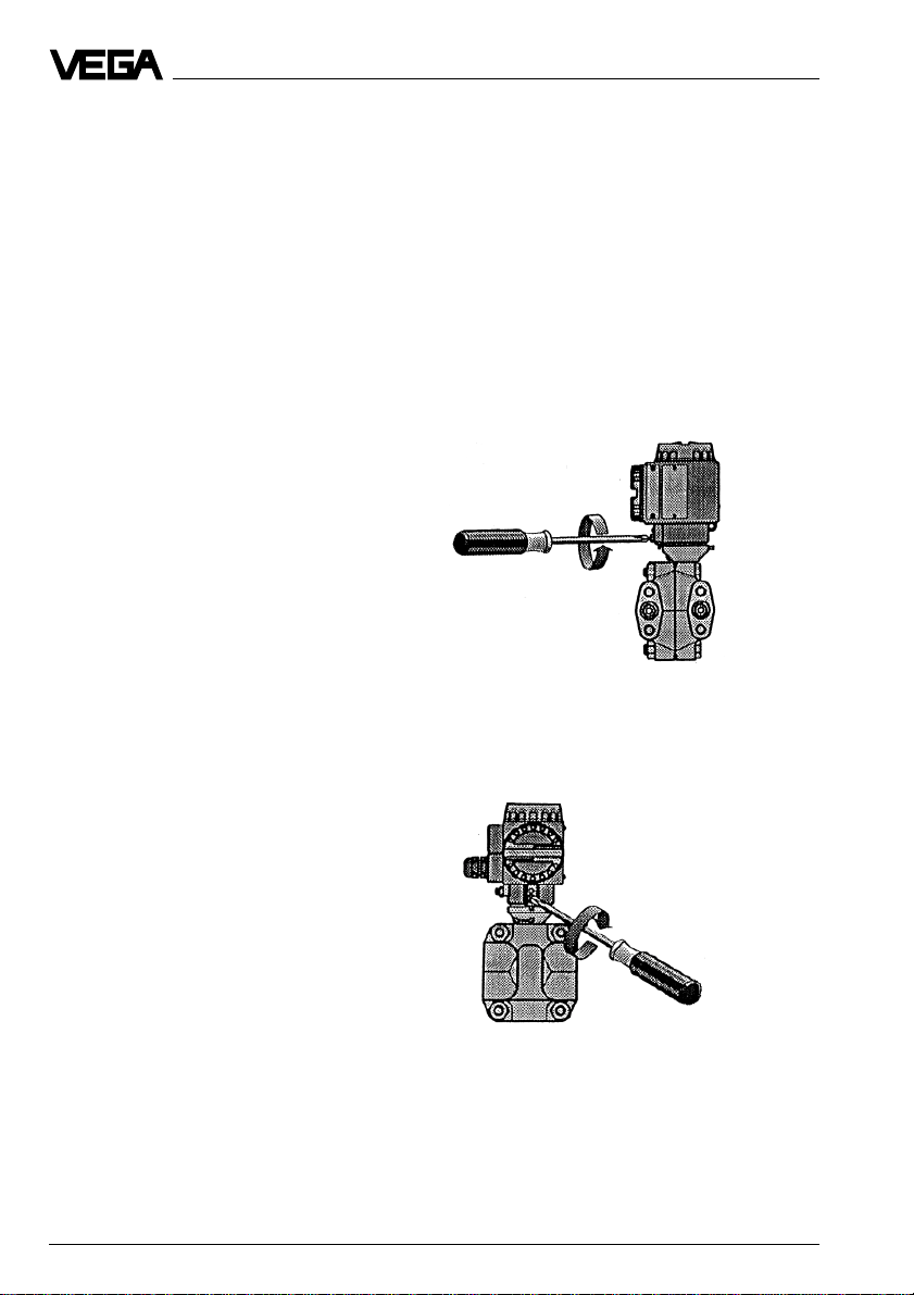
Rotate the electronics housing
After loosening the locking screw below the
electronics housing, the housing can be rotated by approx. 330°. A stop prevents further
turning. Hence the terminal compartment can
be set to an optimum position for cable entry
or the LC-display into an optimum reading
position.
Fig. 2.1 Loosen the locking screw
When the best position is reached, tighten the
locking screw again.
Ambient influences
• Keep the vibration and shock effect to a
minimum.
• Avoid corrosive ambient atmosphere.
• Reduce condensation to a minimum.
Note:
Under arduous ambient conditions, a protective housing is recommended.
22 VEGADIF 34 … 51
Fig. 2.2 Fastening of the locking screw
Page 23

Mounting
Rotating the display
If the integrated display is not correctly positioned it can be rotated in 90°-steps after
opening the housing cover.
Avoid exposure of the electronics compartment and carry out these measures if possible
in a workshop.
1 Unscrew the display cover
2 Push the protruding clamp with a screw-
driver outwards
3 Tilt the display in this position and take
out
Note
Do not turn more than 2 x 90° to the left or
right, otherwise the connection cable may be
damaged.
5 Insert the display into the clamp and
snap-in
6 Replace the outer cover
Remove the protective plugs
Transmitter or isolating diaphragm are provided with protective plastic plugs. Remove
them before installation.
4 Rotate display as needed
VEGADIF 34 … 51 23
Page 24

Mounting
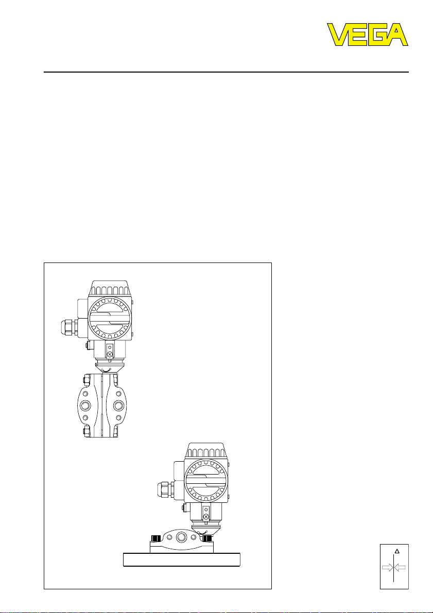
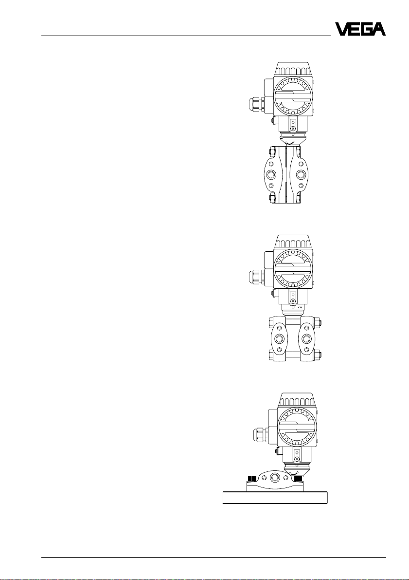
2.3 Mounting
2.3.1 VEGADIF 34, 35 and 51
The differential pressure transmitter mounting
is generally fixed. There are three versions
with VEGADIF 34, 35 and 51:
- pipe mounting (2“-pipe)
- wall mounting
- mounting on a valve block
Hanging the transmitter on the impulse lines is
not recommended, nor with capillary lines.
For correct mounting VEGA offers a universal
mounting kit consisting of:
- a mounting bracket
- a pipe shackle for 2“-pipes (up to outer-ø
63 mm)
- two hexagon nuts M8 with plain washers
- four hexagon screws (7/16 UNF or
M10 x 182))
For easy removal of the transmitter a three or
five valve manifold can be mounted to the
transmitter 1).
In this case the valve block can be mounted
with the mounting kit to a pipe or wall instead
of the transmitter. The impulse lines can be
sealed via valves and the manifold with the
connected impulse lines can be left in place
after removal of the transmitter.
1)
Pipe mounting
Use the complete mounting kit and note the
following procedure:
1 Hold the mounting bracket in the required
direction on the pipe.
2 Insert the u-bolt via the pipe through the
holes of the mounting bracket.
3 Screw two hexagon nuts to the u-bolt and
fasten the bracket by fastening the nuts on
the pipe.
4 Fasten the transmitter to the bracket (the
screws with plain washers pass through the
holes of the bracket into the thread).
Mounting on vertical pipe
approx. dimensions in mm
105
165
9
312,5
+
Z S
-
+
Z S
-
1)
not with VEGADIF 51
2)
M12 x 18 with 420 bar-version of VEGADIF 35
24 VEGADIF 34 … 51
Page 25

Mounting
Mounting on horizontal pipe
Z S
-
+
Wall mounting
Use the following material of the mounting kit:
- bracket
- four hexagon screws
Provide the following material:
- four screws with suitable plugs
Note the following procedure:
1 Screw the bracket by means of the screws
and suitable plugs to the wall.
2 Screw the transmitter to the bracket (the
screws with plain washers pass via the
holes of the bracket to the thread).
Mounting with valve block
1)
The valve block is fastened as described
before by tube or wall mounting.
Procedure:
1 Fasten bracket to a tube or wall.
2 Screw the valve block to the mounting
bracket with two hexagon screws and plain
washers.
The transmitter is normally flanged to the valve
block just before setup of the measurement
loop.
2.3.2 VEGADIF 44 and 45
The following instructions are given for VEGADIF 44 however are also valid for VEGADIF
45.
Open vessel
The minus side of the transmitter is open to
atmospheric pressure. Therefore the open
process connection of the minus side should
point downwards.
Max.
Min.
P
atm
Atmospheric pressure on the minus
side of the transmitter
1) not with VEGADIF 51
VEGADIF 34 … 51 25
Page 26

Mounting
Closed vessel
The minus side of the transmitter is connected
via an impulse line with the vessel and feels
the pressure. The pressure must be above
the maximum level. The impulse line should
have a block valve.
Block
valve
Steam trap
Block
valve
If the static pressure is caused by steam above
the product the minus side is connected via a
condensation leg. Before opening the block
valve the impulse line must be filled via the
condensation pot.
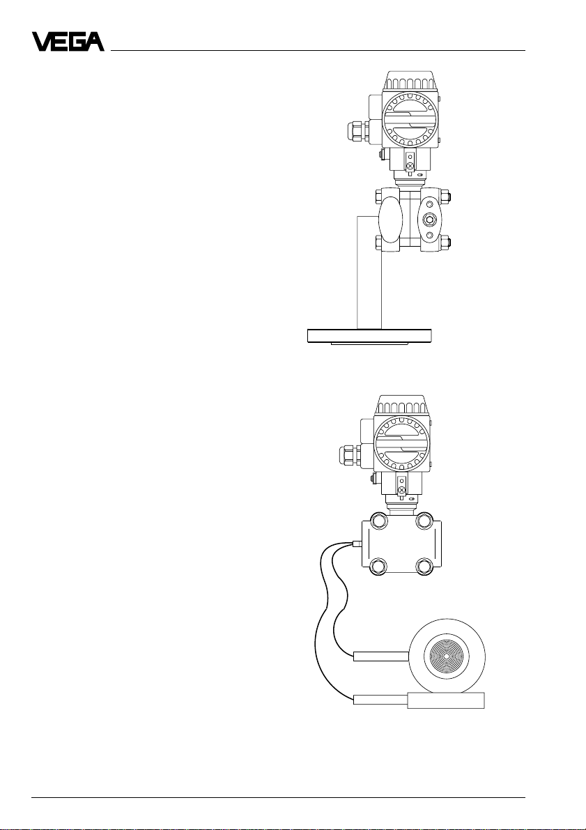
2.3.3 Isolating diaphragm mounting on
VEGADIF 51
The two isolating diaphragms connect the
pressure transmitter with the process. The
dimensions of the cell isolating diaphragm are
dependent to the respective standard flange.
The fastening is made by means of a suitable
blind flange. Depending upon the flange a
seal acc. to DIN 2690 or ANSI B 16.5 must be
used.
Mounting
Blind flange
Isolating diaphragm
Seal
Measuring point
connection flange
Vessel wall
Level measurement
Block
Condensation pot
valve
Condensate
Steam
Max.
Min.
Min.
Recommended mounting
Block
valve
26 VEGADIF 34 … 51
Condensation outlet
Page 27

Mounting
Only permitted with continuous positive pressures.
Differential pressure measurement
-+
Flow measurement
+
-
Avoid buildup on the isolating diaphragm of
solids or by sticky materials. If possible position the flange connections on top of the pipe.
VEGADIF 34 … 51 27
Page 28

3 Electrical connection
Electrical connection
3.1 Connection instructions
The electronics of the pressure transmitters
requires a supply voltage of 11.5 … 45 V DC.
Supply voltage (DC voltage) and current
signal are on the same two-wire connection
cable to the terminals.
This external supply can be provided via a
separate instrument:
- power supply
(e.g VEGASTAB 690)
- processing unit with integral DC voltage
source (e.g. active DCS-input)
- VEGAMET series 500 or 600 signal conditioning instrument, VEGALOG 571 processing system or VEGADIS 371 indication
Note that the external supply source is reliably
isolated acc. to DIN VDE 0106, part 101 from
the mains circuits. The above mentioned systems meet these requirements and protection
class III is therefore ensured.
For electrical connection note the following
instructions:
- The connection must be made acc. to the
specific national installation standards (e.g.
in Germany acc. to the VDE-regulations).
- The wiring between pressure transmitter
and supply can be made by standard twowire cable.
- If strong electromagnetic interference is
expected, use screened cable. The screening must be earthed at the sensor end.
- The connection cable for the external supply
must never be connected to terminal 3 of
the terminal block or to the test plug connection via terminal 1 of the terminal block
(danger of damage to the electronics).
- Housing cover and cable entry must be
tight after electrical connection, so that humidity ingress to the terminal compartment
is avoided.
3.2 Load resistance
Various instruments can be connected to the
signal output of the pressure transmitter, e.g.:
- remote transmission systems
- computers
- indicating instruments
- recorders
- controllers etc.
The total resistance of the connected instruments and the connection cable must not
exceed the value of the max. load resistance.
The load resistance consists of the line resistance RL, the adjustment resistance RX, and the
resistance of the processing system and/or
indicating instrument.
This max. load resistance depends on the
voltage of the external supply and can be
calculated acc. to the following formula:
US – U
R
= –––––––––
Lmax
R
Lmax
US= supply voltage
UKl= terminal voltage
I
max
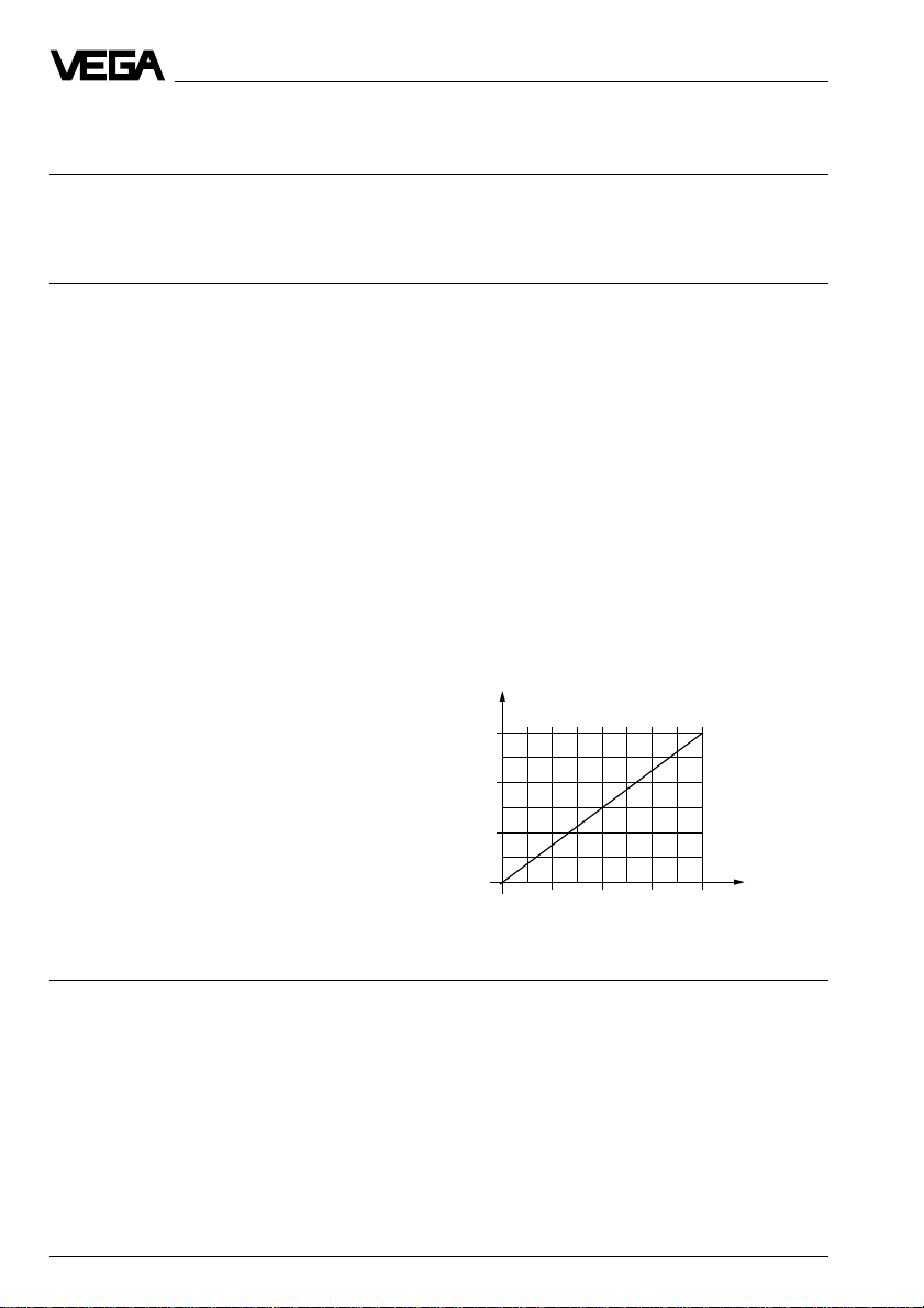
The following load diagram is used for simplified determination of this value:
1560
1000
in Ohm
500
total
Load R
K
I
max
= max. load resistance
1)
= max. current (approx. 23 mA)
0
20 28,5 37 4511,5
Supply voltage US in Volts
28 VEGADIF 34 … 51
Page 29

Electrical connection
3.3 Connections
Electronics powered by the power supply unit
Processing via an indicating instrument.
Ammeter for local testing
1+2–3
–
+
U
Transmitter
terminals
R
Kl
L
analogue / digital
indicating instrument
e.g. VEGADIS
U
A
4 … 20 mA
U
S
+
~
–
Voltage supply
US= power supply
UA= voltage loss in the indication instrument
UKL= terminal voltage (supply voltage)
RL= resistance processing systems and connec-
tion cable (load resistance)
Electronics powered by a VEGA-signal conditioning instrument or a PLC with active
input circuit
Processing is made via the PLC or the VEGAMET signal conditioning instrument.
Ammeter for local testing
–
+
1+2–3
Transmitter
terminals
U
Kl
R
L
4 … 20 mA
PLC active
or
0/4 … 20 mA
U
S
DISBUS
!
Note:
An ammeter for local testing of the output current can be connected between terminal 1 and its
tag. This measurement can be made during operation without interrupting the supply line.
VEGADIF 34 … 51 29
Page 30

Electrical connection
3.4 Ex-applications
Applications in Ex-areas require the use of
approved instruments.
For these applications the appropriate documents (test reports, test and conformity certificates) should be noted. These are supplied
with the appropriate instrument.
Therefore note the attached approval documents (yellow binder) and especially the attached safety data sheet.
The voltage supply in Ex-applications must be
only made via an intrinsically safe circuit.
There are the following possibilities:
- VEGAMET signal conditioning instrument in
Ex-version
- not certified signal conditioning instrument
VEGAMET with VEGA-safety barrier type
145
- Ex-separator (e.g. VEGATRENN 149 Ex)
- indicating and supply instrument VEGADIS
371 in Ex-version.
The legal documents of these instruments
must also be noted.
Application with supply by Ex-separator,
e.g. VEGATRENN 149 Ex
The processing is made by an indicating
instrument in the non-Ex-area.
-
+
1+2-3
U
Kl
Ex-area
Terminals
VEGADIF
Non-Ex-area
e.g. Ex-separator
VEGATRENN
149 Ex
-
U
S
+
4…20 mA
=
~
Ex-application with supply via a VEGA
non-Ex-signal conditioning instrument
with safety barrier type 145
The processing is made via the signal conditioning instrument in the non-Ex-area.
Non-Ex-area
Safety barrier
type 145
VEGAMET in
non-Ex-version
-
+
Ex-area
1+2-3
Terminals
VEGADIF
U
Kl
Note
- Carry out the adjustment only with connected safety barrier (reason: the current
consumption of approx. 300 µA is considered).
- When connecting a VEGADIS 11 Ex the
regulations for wiring of intrinsically safe
circuits should be noted.
Determination of the line length in the
ia-IIC-circuit
The sum of the inner capacitances and inductances of the components must not exceed
the max. permissible values of the ia-IICcircuit.
Example:
ia-IIC-circuit Pressure 1 pce. Line
max. total transmitter overv.arrester L
L
ext/Cext
L
int/Cint
L
int/Cint
0.5 mH 0.2 mH 0.13 mH 0.17 mH
56 nF 11.2 nF 1 nF 44.8 nF
1)
int/Cint
VEGADIS 11
Processing e.g.
indicating instrument
1)
Typical values for unshielded two-wire lines:
L‘ = 0.00065 mH/m; C‘ = 0.00012 nF/m
30 VEGADIF 34 … 51
Page 31

Electrical connection
Calculation of L
L
(cable) = L
int
transmitter) – L
of the cable:
int/Cint
(ia-IIC-circuit) – L
ext
(overvoltage arrester)
int
(pressure
int
= 0.5 mH – 0.2 mH - 0.13 mH
= 0.17 mH
C
(cable) = C
int
sure transmitter) – C
(ia-IIC-circuit) – C
ext
(overvoltage arrester)
int
(pres-
int
= 56 nF – 11.2 nF - 1 nF
= 44.8 nF
Calculation of the cable length:
0.17 mH
I = –––––––––– • m = 262 m
0.65 µH
44.8 nF
I = ––––––––––– • m = 373 m
120 pF *
To be on the safe side, the cable length in this
example should not exceed a value of 250 m.
VEGADIF 34 … 51 31
Page 32

4 Setup
Setup
4.1 Adjustment structure
The differential pressure transmitters can be
setup
- with the PC and the VEGA-adjustment program VVO,
- with the HART® handheld or
- with the integral 4-key adjustment elements.
Adjustment program VVO
With the adjustment program VVO (VEGA
Visual Operating) on the PC you adjust the
sensors in a very comfortable way. The PC
communicates via the interface converter
VEGACONNECT 2 with the sensor. The signal
and supply line is therefore superimposed by
a digital adjustment signal. The adjustment
can be made in any position of the signal line,
naturally also directly on the sensor.
HART® handheld
Beside the PC and the 4-key adjustment elements, the sensors can be also adjusted with
the HART® handheld.
4-key adjustment elements with LCdisplay
If you have neither a PC nor a HART® handheld,
the sensors can also be setup directly with the
integral 4-key adjustment elements.
4.2 Adjustment with 4-key adjustment element
LC-display in operating mode
According to the ordered version your VEGADIF is provided with an integral LC-display.
This display can be retrofitted or removed.
The display is located below the upper housing cover behind a glass pane.
The LC-display provides the following information in the adjustment mode:
Span indication during
full adjustment
Appropriate
pressure value
s
5 .0 0 0
z
Zero indication during
empty adjustment
Position of
zero
Bar graph for measuring span =
span – zero
LC-display
The following examples show possible indication
values.
Example 1: Meas. range -0.5 … 1.5 bar, LCD
in operating mode
Position of
span
D p
-0,5 bar
0 bar
1,5 bar
32 VEGADIF 34 … 51
Display I
- 0 .5 0 0
4 mA
- 0 .0 0 0
8 mA
1 .5 0 0
20 mA
Page 33

Setup
Example 2: Measuring range 0 … 10 bar
D p
0 bar
2,5 bar
10 bar
Display I
0 .0 0
4 mA
2 .5 0
8 mA
1 0 .0 0
20 mA
4-key adjustment elements
Your VEGADIF is provided with the following
direct adjustment elements:
- four adjustment keys
- one step switch
The adjustment keys are located below a slide
laterally on the electronics housing. The slide
is marked with z (zero) and s (span) and can
be moved after loosening of the recessed
head screws. When moving the slide, two adjustment keys are released, when then rotating
the slide, all four adjustment keys are released.
+
Z S
-
First of all the slide releases 2 keys and then
all four keys
Via these four keys in conjunction with the LCdisplay you can carry out the most important
adjustments such as zero, span and bias pressure directly on the transmitter.
++
ZS
-
If you have a VEGADIF without LC-display,
connect to the terminal and to tag 1 an ammeter
with measuring range 0 … 20 mA (e.g. digital
multimeter). For the exact adjustment connect a
precision ammeter. Push the keys with a small
screwdriver.
The second adjustment element, the step
switch, is located below the LC-display; therefore remove the display, as described under
"2.2 Pre-installation“.
The step switch below LC-display
The adjustments on the step switch mean:
- 0 Adjustment with PC or HART®, therefore
damping adjustable from 0 … 40 s
- 2 Damping 0.5 s linear
- 3 Damping 1.0 s linear
- 4 Damping 2.0 s linear
- 5 Damping 4.0 s linear
- 6 Damping 8.0 s linear
- 7 Damping 16.0 s linear
- 8 Adjustment with PC or HART®, there-
fore damping adjustable from 0 … 40 s
- 9 Damping 0 s extracted by root
- A Damping 0.5 s extracted by root
- B Damping 1.0 s extracted by root
- C Damping 2.0 s extracted by root
- D Damping 4.0 s extracted by root
- E Damping 8.0 s extracted by root
- F Damping 16.0 s extracted by root
Current I
Current I
Dp
linear extracted by root
VEGADIF 34 … 51 33
Dp/p
Page 34

Setup
Display zero
1 Push +z or –z key
2 Monitor the displayed value and release the
key again.
After approx. 2 s the indication resets automatically to operating mode.
Example for display of zero:
Meas. range Display
-3…0 bar
0…1,5 bar
2,5…-0,5 bar
Display span
1 Push +s or –s key
2 Monitor the displayed value for s and re-
lease the key again
The display resets automatically to operating
mode after approx. 2 s.
Examples for display of span:
Meas. range Display
-3…0 bar
1)
z
- 3 .0 0 0
z
0 .0 0 0
z
2 .5 0 0
s
0 .0 0 0
Data of the factory setting
Measuring range
Your VEGADIF is calibrated acc. to the order.
The calibration data is stated on the calibration
plate, e.g. 0 … 1000 mbar.
For this measuring range:
- The 4 mA-signal is coordinated to the first
pressure value (in the example 0 mbar).
- The 20 mA-signal is always coordinated to
the second pressure value (in the example
1000 mbar).
Check if the calibrated measuring range corresponds to the application and if necessary
readjust, see the following section "Adjustment“.
Integration time
A factory set integration time of 0 s is supplied. Via the step switch this time can be
changed from 0 … 16 s, with the PC to
0 … 40 s, to achieve an increased smoothing
of the output signal.
Output characteristics
As factory setting a linear characteristics is
adjusted. A square root output can be selected with the step switch.
Electronics replacement
The calibration data is stored in the EEPROMmemory of the electronics. Always check the
data when replacing the electronics and
modify if necessary.
Adjustment
0…1,5 bar
2,5…-0,5 bar
1)
This adjustment effects an inversion of the current
output
34 VEGADIF 34 … 51
s
1)
1 5 0 0
- 5 0 0 .0
First note the adjustment ranges for zero and
span. The values are stated under "1.4 Technical data - Transmission reaction“. Make sure
that your requested values are within the
possible adjustment range.
Page 35

Setup
Two methods are available for adjustment
- adjustment without pressure (dry)
- adjustment with pressure (wet)
The dry adjustment can be made before
mounting in the workshop or after mounting at
the measuring point. Note with the adjustment
before mounting, that the position of the transmitter corresponds to the intended installation
position. This is particularly necessary for
VEGADIF 45 and 51 with isolating system or
capillaries. Use for sensors without display a
precision ammeter (class 0.03 or better) to
adjust the current output.
Adjustment without pressure (dry)
Reduce zero
1 Push key z– twice and hold.
2 Note the change of the current.
3 When the requested current value is
reached, release z–.
4 The display resets automatically to operat-
ing mode after approx. 2 s and the adjusted
value is saved.
Example:
given: 0 … 1000 mbar, (z = 0 mbar,
s = 1000 mbar)
z to be changed to: z = -500 mbar
Example:
given: 0 … 1000 mbar, (z = 0 mbar,
s = 1000 mbar)
to be changed to: s = 500 mbar
Push the key s– twice and hold until 500 mbar
are adjusted.
Adjustment with pressure (wet)
For the adjustment with pressure, VEGADIF
must be connected to a variable pressure
source, e.g.:
- a pressure calibrator
- directly to the process
Adjust zero with display
1) Set pressure precisely for zero (e.g.
0 bar) and check via the display.
2) Push key z+ and z– together.
The pressure (e.g. 0 bar) corresponds to the
output current 4 mA.
Adjust span with display
1) Set pressure precisely for span (e.g.
1 bar) and check via the display.
2) Push key s+ and s– together.
Increase zero
Push the key z+ twice and hold. The procedure is the same as above.
Reduce span
1 Push key s– twice and hold.
2 Note the change of the current.
3 When the requested current value is
reached, release s–.
4 The display resets automatically to operat-
ing mode after approx. 2 s and the adjusted
value is saved.
VEGADIF 34 … 51 35
The pressure (e.g. 1 bar) corresponds to the
output current 20 mA.
Adjust zero without display
1) Set pressure precisely for zero (e.g.
0 bar) and check via an external pressure
calibrator.
2) Push key z+ and z– together.
The pressure (e.g. 0 bar) corresponds to the
output current 4 mA.
Page 36

Setup
Adjust span without display
1) Set pressure precisely for span (e.g.
1 bar) and check via an external pressure
calibrator.
2) Push key s+ and s– together.
The pressure (e.g. 1 bar) corresponds to the
output current 20 mA.
Adjust zero/span without display however
with current meter
For adjustment a control instrument with measuring range 0 ... 20 mA is connected to terminal 1 and tag 1.
1) Set pressure precisely for zero (e.g.
0 bar) and check via an external pressure
calibrator.
2) Adjust with keys z+ and z– a current of
4 mA.
The pressure (e.g. 0 bar) corresponds to an
output current 4 mA.
3) Set pressure precisely for span (e.g.
1 bar) and check via an external pressure
calibrator.
4) Adjust with the keys s+ and s– a current
of 20 mA.
Example:
Meas. range 0 … 1000 mbar
Reference pressure span ps = 1000 mbar,
zero pz = 0 mbar, reference pressure
p = 250 mA (750 mbar)
250 mbar – 0 mbar
Iz = 4 mA + 16 mA • ––––––––––––––––––––
1000 mbar – 0 mbar
Iz = 8 mA
750 mbar – 0 mbar
Is = 4 mA + 16 mA • –––––––––––––––––––
1000 mbar – 0 mbar
Is = 16 mA
Bias pressure
Bias pressure is the pressure indicated although a differential pressure of 0 mbar is
present at the pressure tappings. The bias
pressure is caused by unequal hydrostatic
pressures 1) on the measuring cell.
The following relation is valid:
Pressure indication = Sensor pressure – Bias
pressure
The pressure (e.g. 1 bar) corresponds to an
output current 20 mA.
Example:
Pressure indication: 0.025 bar
Sensor pressure: 0.035 bar
Bias pressure: 0.010 bar
Note:
When only intermediate values are available
0.025 bar = 0.035 bar – 0.010 bar
for the reference pressures, the current to be
adjusted can also be calculated:
Note:
p – p
I = 4 mA + 16 mA • –––––––––
p = reference pressure
ps= pressure at span
pz= pressure at zero
ps – p
z
z
- The adjustment of the bias pressure must
be carried out before the adjustment of zero
and end, as these values had been modified.
- The adjustment of the bias pressure does
not influence the current output. The signal
current and its characteristics are not modified.
1)
This can be caused e.g. by non-level pressure tappings and therefore different needs in the impulse lines, by
the installation of the capillary lines or the position of the measuring cell itself (max. 2 mbar when tipped by
90°).
36 VEGADIF 34 … 51
Page 37

Setup
Indicate bias pressure
1) Push keys z+ and s+ once together.
2) Adjusted bias pressure is indicated.
3) After approx. 2 s the display resets automatically to operating mode.
Save/take over bias pressure
1) Push keys z+ and s+ twice together. The
available pressure value is taken over as
bias pressure.
2) After approx. 2 s the display resets automatically to operating mode and shows
0.000 bar. Therefore the available pressure (0 bar) was taken over as bias pressure (correction value).
Delete bias pressure
1) Push the keys z– and s– twice together.
2) After approx. 2 s the display resets automatically to operating mode and shows
the value of the uncorrected bias pressure.
Lock/unlock keys
Lock
1) Push keys z+ and s– once together.
2) "Prot“ = protected appears (locked).
3) After approx. 2 s the display resets automatically to operating mode.
Unlock
1) Push keys z– and s+ once together.
2) "Free“ = unlocked appears.
3) After approx. 2 s the display resets automatically to operating mode.
Integration time and output characteristics
An integration time of 0, 1, 2, 4, 8, 16 s can be
adjusted via the step switch to smooth the
output signal of your VEGADIF. The output
characteristics for pressure, level and flow
can be selected as line or square root.
The integration time is the time required by the
output to reach 63 % of the actual change
after a step change of the differential pressure. After three times the adjusted integration
time, the current output signal will have
reached 95 % of the step change.
Explanation:
- an integration time of 0 s means tracking of
the current output without additional delay
- an integration time of 16 s means that the
output has reached its final value only after
more than one minute.
Adjust the integration time and the output
characteristics acc. to the table. All figures
indicate the switch positions:
Characteristics linear by root
Integration time
0 s 1 9
0.5 s 2 A
1 s 3 B
2 s 4 C
4 s 5 D
8 s 6 E
16 s 7 F
I ~ DpI ~ ÖDp/Dp
I
Dp
I
max.
Dp
The positions 0 and 8 enable the adjustment
with PC (VVO) or with HART® handheld by which
you can also adjust the integration time of
0 … 40 s.
VEGADIF 34 … 51 37
Page 38

Setup
4.3 Adjustment with HART® handheld
Beside the adjustment with the 4-key adjustment element in the sensor and the adjustment with
the PC and the adjustment software VVO a VEGADIF can be also operated with a HART® handheld. If
the inner resistance of the voltage supply is less than 250 W, a resistor of RX = 250 W 1/4 W must be
looped into the signal/connection line during adjustment.
The digital adjustment and communication signals would be shortcircuited via too small resistances of the supply current source or the processing system so that the sensor communication
would not be assured.
Electronics powered by PLC with active input circuit
+
PLC
-
Ri > 250
+
PLC
250
-
Ri < 250
38 VEGADIF 34 … 51
Page 39

Setup
Electronics powered by power supply unit
Ammeter for local testing
analogue / digital indicating instrument
-
+
1+2-3
Transmitter
terminals
U
S
-
~
+
Supply voltage
(Ri < 250 W)
U
Kl
U
4 … 20 mA
U
A
K
R
X
Note:
An ammeter for local testing of the output current can be connected between terminal 1 and its
tag. This measurement can be made during operation without interrupting the supply line.
Electronics powered by a VEGA-signal conditioning instrument
Ammeter for local testing
Transmitter
terminals
1+2-3
-
+
U
U
Kl
4 … 20 mA
K
U
S
R
X
0/4 … 20 mA
DISBUS
!
If the differential pressure transmitters are operated on a VEGA-signal conditioning instrument, you
have to connect the sensor via a resistor acc. to the following schedule to the signal conditioning
instrument during the HART® adjustment. Together with the inner resistor of the signal conditioning
instrument, the resistance value of 250 W required for the HART® instrument is reached.
If the resistor of the processing system or the voltage supply is more than 250 W, there is no
"Adjustment resistor“ required.
VEGADIF 34 … 51 39
Page 40

Setup
+
PLC
-
Ri > 250
VEGALOG VEGAMET
Rx
VEGA-signal conditioning instr. R
X
VEGAMET 513, 514, 515, 602
VEGATRENN 544
VEGATOR 521…527 50 … 100 Ohm
VEGAMET 614 no additional
VEGADIS 371 resistance
required
VEGAMET 601 200 … 250 Ohm
VEGASEL 643 150 … 200 Ohm
VEGAMET 513 S4, 514 S4
515 S4,
VEGALOG EA-card 100 … 150 Ohm
40 VEGADIF 34 … 51
Page 41

Setup
The most important adjustment steps
On the following two pages you see the
HART®-menu plan to differential pressure
transmitter VEGADIF.
The most important adjustment steps are
marked in the menu plan with the figures
A … F. Setup the sensor in the sequence
A…F.
A: Empty adjustment without medium
(
zero
– dry)
B: Full adjustment without medium
(
span
– dry)
A1: Empty adjustment with medium
(
zero
)
B1: Full adjustment with medium
(
span
)
C: LOW/HIGH SENSOR CAL.
(only if required, see following diagram)
Here the proportionality defined by the
empty and full adjustment between pressure and signal current (characteristics)
can be shifted in the position (vertically).
The characteristics can be quasi hold or
shifted in the range of the zero point or the
range of the measuring range final value
(see right diagram), to get a requested
signal current in the zero point or at the
measurement end.
Adjustment characteristics
(e.g. -70 … 80 mbar) after
LOW/HIGH SENSOR CAL.
was carried out (point C)
LOW SENSOR CAL.
-100
mbar
zero
- 50
D: BIAS PRESSURE AUTOM.
Means that the indication can be set to
zero, to suppress a certain pressure in
the indication. The output characteristics
and the signal current are not concerned.
E: Damping of the signal output.
The pressures on the measuring cell are
integrated and averaged in the given
times, to get a stable indication and signal
current output even in case of quick pressure fluctuations.
F: Selection of the physical unit
mA
HIGH SENSOR CAL.
○ ○ ○ ○ ○ ○
20
19
18
17
16
15
14
13
12
11
10
9
8
7
6
5
0
Adjustment characteristics
(e.g. -70…80 mbar)
after empty/full adjustment
50 100
○ ○ ○ ○ ○ ○ ○ ○○○○○○○○○○○○○○○○○○○○○
span
mbar
VEGADIF 34 … 51 41
Page 42

HART® menu plan VEGADIF
Setup
Switch on:
Hart Communicator
Self T est
in Progress
Firmware Rev: F2.2
Module Rev: 3.6
01992-96 FRSI
after approx. 20 s
Generic: 10956186
Online (Generic)
1 Device setup
2 PV 2.633 mbar
3 PV AO 4.014 mbar
4 PV LRV 0.000 mbar
5 URV 3000.000 mbar
HELP SEND
Setup the sensor in the sequence of the letters A,
B, C and D (dry adjustment: adjustment without
medium).
For the adjustment with medium, setup the
sensor in the sequence A1, B1, C and D
Generic: 10956186
Device setup
1 Process variables
2 Diag/Service
3 Basic setup
4 Detailed setup
5 Review
SAVE HOME
Generic: 10956186
PV
2.405 mbar
HELP EXIT
Generic: 10956186
A01
3.987 mA
HELP EXIT
1
2
3
Generic: 10956186
Process variables
1 Snsr 2.684 mbar
2 AI % rnge 0.090
3 AO1 4.014
HELP SAVE HOME
Generic: 10956186
1 PV LRV 0.000 mbar
2 URV 3000.000 mbar
HELP HOME
Generic: 10956186
– WARNING –
Return control loopo
to automatic control
OK
Generic: 10956186
– WARNING –
Pressing ÒK`will
change device output.
Put loop in manual.
ABORT OK
Generic: 10956186
1 PV LRV 0.000 mbar
2 URV 3000.000 mbar
1.1
Important menu
windows
Less important
menu windows
Dry adjustment:
Empty and full adjustment
without medium
(with medium see next
page)
Generic: 10956186
1 PV LRV 0.000 mbar
2 URV 3000.000 mbar
HELP HOME
Generic: 10956186
1 PV LRV 0.000 mbar
2 URV 3000.000 mbar
HELP HOME
4
5
HELP SEND HOME
Generic: 10956186
PV LRV
A
B
0.000 mbar
0.000 mbar
HELP DEL ESC ENTER
Empty adjustment without
medium
Generic: 10956186
PV URV
3000.000 mbar
900.300 mbar
HELP DEL ESC ENTER
Full adjustment
without
medium
continue as under A
(figure 4.1 or 5.1)
4.2 (5.2)
4.1
(5.1)
42 VEGADIF 34 … 51
Page 43

Setup
1.2.2
Simulation:
Output of individual current
values for test purposes
1.2.3
A1
B1
Generic: 10956186
Tag
10956776
LEV 34
HELP DEL ESC ENTER
Generic: 10956186
PV Snsr unit
mbar
mbar
g/Sqcm
kg/Sqcm
Pa
Generic: 10956186
Range values
1 PV LRV 0.000 mbar
2 URV 3000.000 mbar
3 LSL -3000.000 mbar
4 USL 3000.000 mbar
HELP HOME
Generic: 10956186
Device information
1 Distributor
2 Model
3 Dev id
4Tag
5 Date **/**/**
HELP SA VE HOME
6 Schreibgeschützt
7 Beschreibung
8 Nachricht
9 PV Sens. Seriennr.
Werknummer
Revisionsnummer
1.4.1
ESC ENTER
Measured value
Change measuring unit
Info on lower and upper
measuring range limit as well
as the min. span (also the
sensor characteristics values)
1.4.2
Adjustment of the integration time
Adjustment of zero and span
Adjustment of zero and span
linear
Display of the level in % of the
adjusted span
Wet adjustment:
Empty and full adjustment
with medium
(see next page)
1.3.1
New measurement
loop designation to
save with ENTER
and SEND
1.3.2
1.3.3
Display of the used
}
measuring range
Display of
}
measuring
range
1.3.4
see next
page
Generic: 10956186
PV
2.676 mbar
HELP EXIT
Generic: 10956186
PV % rnge
0.086 %
HELP EXIT
Generic: 10956186
AO1
4.014 mA
HELP EXIT
Generic: 10956186
Diag/Service
1 Test device
2 Loop test
3 Calibration
4 D/A trim
HELP SAVE HOME
Generic: 10956186
Basic setup
1Tag
2 PV Unit
3 Range values
4 Device information
5 PV Xfer fnctn
HELP SA VE HOME
6 PV Damping
Generic: 10956186
Dateiled setup
1 Sensors
2 Signal condition
3 Output condition
4 Device information
SAVE HOME
1.1.1
Safety
enquiry
Acknowledge-
1.1.2
1.1.3
1.2
Correction possibility of the
digital/analogue converter in
conjunction with a prevision
ammeter as reference
instrument (only for service
purposes).
1.3
1.4
as menu
1.3.4
ment
Transmission function (linear)
Adjustment of the integration time
Generic: 10956186
Sensors
HELP SAVE HOME
Generic: 10956186
Choose analog output
level
14 mA
2 20 mA
3 Other
4 End
ENTER
Generic: 10956186
Calibration
HELP SEND HOME
ABORT
1 Apply values
2 Enter values
D
C
1 PV 2.601 mbar
2 PV Snsr unit
3 Sensor information
Generic: 10956186
Signal condition
1 Snsr Damp 0.000s
2 URV 3000.000 mbar
3 AI LRV 0.000 mbar
4 Xfer fnctn Linear
5 AI % rnge 0.082 %
HELP SAVE HOME
VEGADIF 34 … 51 43
Page 44

Continuation HART® menu plan VEGADIF
Wet adjustment
Generic: 10956186
Set the:
Generic: 10956186
Calibration
1 Apply values
2 Enter values
HELP SAVE HOME
1.2.3
Safety
enquiry
Acknowledge
1 4mA
2 20mA
3 Exit
ABORT ENTER
1.2.3.1
Empty adjustment with
medium
Generic: 10956186
Apply new 4ma input
ABORT OK
Full adjustment with
medium
Generic: 10956186
Apply new 20ma input
ABORT OK
Setup
Generic: 10956186
Analog output
1 AO1 4.014 mA
2 AO Alrm typ Hi
3 Loop test
4 D/A trim
5 Skaled D/A trim
HELP SAVE HOME
Dry adjustment
Generic: 10956186
Enter values
HELP HOME
Generic: 10956186
AO Alrm typ
Hi
1.4.3.1
Generic: 10956186
WARNING–Loop should be
removed from
automatic control
}
1.2.3.2
1 PV LRV 0.000 mbar
2 URV 3000.000 mbar
3 PV USL
4 PV LSL
1.4.3.1.2
EXIT
ABORT OK
Correction possibility of the digital/analogue
converter in conjunction with a precision
ammeter as reference instrument (only for
service purposes)
Empty adjustment without medium (as
menu 4.1 or 4.2 on previous page)
Display of the
}
measuring
range
Low: In case of failure current output
High: In case of failure current output
Generic: 10956186
Choose analog output
level
14 mA
2 20 mA
3 Other
4 End
ABORT
ENTER
goes to 22 mA
goes to < 3.6 mA
1.4.3.1.3
Full adjustment
without medium
Set signal current
for test purposes
to a certain value.
1.4.3.2
from menu window
1.4.
menu point 3
Condition output
Generic: 10956186
Output condition
1 Analog output
2 HART output
SAVE HOME
1.4.3
Generic: 10956186
HART output
1 Poll addr
2 Num req preams 0
3 Burst mode Off
4 Burst option
HELP SAVE HOME
44 VEGADIF 34 … 51
Page 45

Setup
A1
B1
Generic: 10956186
Current applied
Process value: 2.492
mbar
1 Set as 4mA value
2 Read new value
3 Leave as found
ABORT ENTER
Generic: 10956186
Current applied
process value: 2.498
mbar
1 Set as 4mA value
2 Read new value
3 Leave as found
ABORT ENTER
Generic: 10956186
PV LRV
A
B
2.547 mbar
2.547 mbar
HELP DEL ESC ENTER
Generic: 10956186
PV LRV
2.547 mbar
2.547 mbar
HELP DEL ESC ENTER
1.2.3.1.1
1.2.3.1.2
1.2.3.2.1
1.2.3.2.1
1.2.3.1.1.1
Generic: 10956186
Set the:
14 mA
2 20 mA
3 Exit
ABORT
ENTER
Generic: 10956186
Set the:
14 mA
2 20 mA
3 Exit
ABORT ENTER
Generic: 10956186
Enter values
HELP SEND HOME
Generic: 10956186
Enter values
HELP SEND HOME
Quit the menu with
„3 Quit“
1.2.3.1.2.1
Quit the menu with
„3 Quit“
1 PV LRV 2.547 mbar
2 URV 3002.547 mbar
3 PV USL
4 PV LSL
1 PV LRV 2.547 mbar
2 URV 3002.547 mbar
3 PV USL
4 PV LSL
Continue as in menu 4.1
on previous page
Continue as in menu 4.2
on previous page
Multidrop operation
1.4.3.2
The sensor provides the measured value also digitally in
the HART-protocol beside the 4…20 mA signal.
• Poll address zero:
The sensor takes a level dependent
4…20 mA current and delivers the level
simultaneously as digital HART-signal.
• Poll address 1…15:
The output signal is only available as digital
HART-signal (HART-signal).
The 4…20 mA signal is no longer provided,
and the sensor current is fixed adjusted to 4 mA.
Generic: 10956186
Burst–mode
Off
Off
On
Not Used
None
Unknown
Spcl
Generic: 10956186
Burst–option
PV
% range/current
Process vars/crnt
HELP ESC ENTER
1.4.3.2.3
ESC ENTER
Generic: 10956186
Poll addr
0
0
HELP DEL ESC ENTER
Sensor signals measured values only upon request of the master
Sensor signals the measured value selected in „Burst Option“ without master
enquiry
Choice is not supported
1.4.3.2.4
Selection of the unit for the measured value
provided digitally without master or host
enquiry:
- as process variable (e.g. mbar)
- as percentage value or
- as signal current.
VEGADIF 34 … 51 45
Page 46

4.4 Adjustment with PC
2
2
VEGACONNECT 2
Setup
4 … 20 mA
1)
2
2
PLC
1)
If the inner resistance of the power
supply or the processing system (PLC)
is less than 200 W, a resistor of 200 W
to 350 W must be switched into the
connection cable during adjustment.
The digital adjustment signal would be
extremely damped or shortcircuited via
too small input resistors so that the
digital communication with the PC would
no more be ensured.
For connection of the PC to the pressure transmitter, you require the interface converter VEGACONNECT 2.
When you have connected the PC with the
adjustment software to your measuring system,
• first switch on the power supply of the pressure transmitter.
Connection of the PC
Insert the VEGACONNECT into the standard
connection of the PC and connect the two-wire
line of VEGACONNECT to the pressure transmitter or the signal/supply line of the pressure
• switch on the PC and start the adjustment
software VVO.
• in the initial screen you choose with the
arrow keys or with the mouse the point
"Planning“ and click to "OK“.
transmitter.
You are asked for the identification.
Before starting the setup:
Do not be confused by the many figures,
• Enter under name "VEGA“.
• Also enter under password "VEGA“.
adjustment steps and menus on the following
pages. Just carry out the setup with the PC step
by step and soon you will no more require the
following pages.
The adjustment program VEGA Visual Operating (VVO), in the following just called VVO,
gets in direct contact with the connected sensor…
46 VEGADIF 34 … 51
Page 47

Setup
…and shows you after a few seconds if, with
which sensor and where a connection exists.
Note:
When connecting the adjustment software
(VVO) to a sensor of which data had been
already saved, you will get the information if
the requested data should be transferred to
the sensor or if you want to transfer the sensor
data to the database of the VVO (and are
therefore overwritten).
In the menu "Modify meas. loop configuration“
you can coordinate to the measurement loop
instead of the sensor number first of all a name
(e.g. Tank 10) and a measurement loop designation (e.g. cleaning detergent).
• Confirm the adjustment with "OK“ and after
saving you are again in the main menu window.
Adjustment
Configuration
• Click in the main menu window to the menu
"Configuration/Measurement loop/Modify“.
This is the first step for the setup of the sensor.
VEGADIF 34 … 51 47
In the menu "Instrument data/Parameter adjustment“ you now carry out all important sensor adjustments.
• Choose the menu "Instrument data/Parameter adjustment“.
Page 48

• Confirm the warning with "OK“.
In the heading you see the previously entered
measurement loop name and description.
• Now choose in the menu window "Instrument data parameter adjustment“ the menu
point "Adjustment“.
• Click in the menu window "Adjustment“ to
"zero/span“.
Setup
In the example this is a pressure transmitter
with a measuring range of -80 … +80 mbar,
by which negative pressures (partly evacuation) are measured. The min. value was adjusted to -80 mbar and the max. value (span)
to 80 mbar (i.e. meas. range end).
• Confirm your adjustment with "OK“ and after
a short data transmission to the sensor you
are again in the menu window "Adjustment“.
• Quit all menu windows with "Quit“ and you
are again in the initial menu.
You can carry out the min/max. adjustment
with medium or without medium. When you
want to carry out the adjustment with medium,
you have to carry out the min. adjustment with
emptied vessel and the max. adjustment with
filled vessel.
If the indication does not show zero at zero
pressure after the adjustment of the meas.
begin, it can be corrected to zero (position
adjustment). Here the proportionality between
pressure and signal current (characteristics)
defined by the empty and full adjustment can
be shifted in the position (vertically). The char-
Offset correction
It is therefore comfortable and quick to carry
out the adjustment without medium as shown in
the example.
acteristics can be quasi hold and shifted in the
range of the zero point. This corresponds e.g.
to the menu "LOW SENSOR CALIBRATION“ in
the HART® menu.
• Choose in which unit you want to carry out
the adjustment.
• Enter the pressures which should correspond in your application to 0 % and 100 %
and push "OK“.
48 VEGADIF 34 … 51
Page 49

Setup
• Choose in the initial menu "Instrument data/
Parameter adjustment“ the point "Additional
functions“.
• Click to "Offset correction“.
• When the sensor is unpressurized and in
installation position, confirm the safety enquiry with "OK“.
• Click to "Correct“.
The sensor value is now correctly provided
with 0.0 bar. Also compare the diagram under
"4.3 Setup with HART® handheld“.
Linearisation
In the menu "Instrument data/Parameter adjustment/Conditioning/Linearisation“ you coordinate a volume to the level. The relation of level
and volume is described in so called linearisation curves.
You see the current sensor value and the
measuring cell pressure where the last correction was carried out.
VEGADIF 34 … 51 49
• Click to "Instrument data/Parameter adjustment“, then to "Conditioning“ and finally to
"Linearisation“.
Page 50

Setup
First of all a linear relation is displayed (the
function is a straight line).
In the field "Transfer measured value“ the
actual pressure in percent of the adjusted
span is displayed. You have adjusted the
span with the min./max. adjustment. In our
example this is in the range of
50 … 1000 mbar.
The user programmable curve is generated
by index markers consisting of the value pairs
"Linearised“ (volume in percent or in the selected unit) and "Percentage value“ (level in
percent).
Gauging by liters
You can choose four linearisation curves:
linear, cylindrical tank, spherical tank and user
programmable curve.
In the characteristics of the example (evacuated vessel) you see four index markers or
value pairs. There is always a linear interpola-
tion between the index markers.
Under "User programmable curve“ you can
enter an own linearisation curve as relation
between level in percent or pressure in percent (percentage value) and the volume (lin-
• Click to "Show scaled values“, to have the
adjusted meas. unit displayed on the y-axis
(bottom left in the menu window).
earised).
Index marker 1 is at 0 % level or pressure
• Therefore choose "User programmable
curve“ and then "Edit“.
(percentage value [%]) corresponding to an
actual pressure of 0 mbar.
Note!
When you want to enter an own linearisation
curve, you have to enter two or more index
markers, otherwise the transmitter will fail.
50 VEGADIF 34 … 51
Page 51

Setup
Index marker 2 is at 30 % level or pressure
and 5 % volume.
Index marker 3 is at 70 % level or pressure
and 35 % volume.
Index marker 4 is at 100 % level or pressure
and 100 % volume (100 liters).
1000 mbar
Vacuum
Saline
solution
= 100 liters
700 mbar
= 35 liters
300 mbar
= 5 liters
Again in the menu window "Conditioning“ you
can enter with the menu point "Integration time“
a measured value integration. This is useful for
fluctuating product surfaces to compensate a
permanently changing measured value indication and output. As a standard feature an
integration time of 0 seconds is adjusted.
• Quit the menu with "OK“.
You are again in the menu window "Instrument
data parameter adjustment“.
Measurement loop data
• Click in the menu window "Instrument data
parameter adjustment“ to "Meas. Loop
Data“.
VEGADIF
0 mbar
= 0 liters
You can enter max. 32 index markers (value
pairs).
• Quit the menu with "OK“.
• Confirm the message with "OK“ and your
individual linearisation curve will be saved in
the sensor.
You get all sensor information. With the point
"reset“ you delete the pressure and temperature history which is saved in the sensor.
VEGADIF 34 … 51 51
Page 52

Outputs
• Click in the menu window "Instrument data
parameter adjustment“ to "Outputs“ and
then in the menu window "Outputs“ to "Current output“.
The menu window "Current output“ opens.
Choose here the reaction of the signal current in
case of failure (22 mA or no change). With "no
change“ the transmitter keeps in case of failure
the actual current value and does not go to the
failure current of 22 mA.
Conditioning
Setup
The menu window "Conditioning“ opens.
• Click to "Scaling“.
In the menu window "Scaling“ you choose the
figure and the physical unit to be displayed (if
available) of the transmitter.
• Click to "Instrument data/Parameter adjustment/Conditioning“.
Display of measured value and back-up
See manual "VEGA Visual Operating (VVO)“.
Simulation
In the menu window "Simulation of outputs“
you can simulate the filling of the vessel or the
signal current. You therefore set the indication
and the signal current to the requested value.
For further information see “Manual VEGA Visual
Operating“.
52 VEGADIF 34 … 51
Page 53

Installation connections
5 T ypical installation
connections
5.1 Valves
For VEGADIF 34 and 35 the use of three or
fivefold valve blocks which can be directly
flanged to the transmitter are recommended.
These offer the following advantages:
- Mounting and dismounting of the transmitter
are possible without interrupting the process.
- For the fivefold valve block two valves for
vent drain are provided.
Typical valve connections with the
threefold valve block
(standard connection)
For impulse lines a block valve each should
be provided at the pressure tapping point.
The threefold valve block includes two inlet
valves and one equalization valve.
The two inlet valves are used to isolate the
measuring cell from the impulse lines.
The equalization valve is used for zero-point
adjustment of the transmitter especially in flow
and level measurement.
T ypical valve connections for a five
valve block
(connection also in liquids)
For each impulse line a block valve should be
provided at the pressure tapping point. The
five valve block includes two inlet valves and
one equalization valve as well as in addition
two blow down valves. This connection is also
suitable for aggressive liquids.
The two inlet valves are used to isolate the
measuring cell against the impulse lines.
The equalization valve is used for zero-point
adjustment of the transmitter especially in the
flow and level measurement.
Two additional valves are used for drain-off in
the impulse lines.
For draining observe the following procedure:
1 Close inlet valves
2 Open blow down valves
In this way the impulse lines are cleaned
throughout.
from the pressure
tappings
Block valves
Three valve block
Inlet valves
to the transmitter
VEGADIF 34 … 51 53
Equalization valve
from the pressure
tappings
to the
transmitter
to outlet
Block valves
Five valve block
Inlet valves
Blow down valves
Equalization valve
Page 54

Installation connections
5.2 Impulse lines
The impulse lines are used for pressure transmission from the pressure tappings to the
transmitter. The following regulations must be
observed for running the impulse lines so that
the measured pressure reaches the sensor
unaltered:
- Lines with 12 x 1.5 mm or more should be
used (see e.g. DIN 19 210, impulse lines for
flow measuring systems).
- The line material must be corrosion resistant, suitable for the measured product.
- The impulse lines must be as short as possible and must be earthed; avoid bending.
- The impulse lines must have a gradient of at
least 10 % (10 cm per meter); preventing
buildup.
- Ensure that the whole measurement system
(transmitter, high and low side impulse lines
etc.) is installed in the same aggregate
condition, even temperature conditions.
- Both impulse lines should be at the same
temperature (differential pressure measurement depends on the density); hence the
impulse lines must be routed close together;
if necessary isolate or couple thermally.
- If necessary the impulse lines should be
fastened with pipe clamps.
- It is recommended to connect the impulse
lines via multiple valve blocks to the transmitter; this ensures simple mounting and
dismounting of the transmitter without interruption of the process.
Connection of the impulse lines
The impulse lines must be cleaned before
connecting to the transmitter:
- In applications with gases blow through with
compressed air.
- In applications with liquids use a suitable
cleaning liquid.
Contamination such as e.g. welding or pickling
residues must not penetrate the process
flanges (causing errors).
Before connecting the transmitter, the impulse
lines to the block valves or valve block must
be tested for leaks.
The impulse line with the higher pressure must
be connected to the plus side of the transmitter, the impulse line with the lower pressure to
the minus side of the transmitter.
Connection of impulse lines direct to the
transmitter
In this case the following connection options
exist:
- with cutting ring threading (non-soldered
taper-bush) to the 1/4“ NPT, 1/2“ NPT or RC 1/4“
NPT female threads of the process connection to the transmitter.
- with separate oval flange adapter to the
1
/2“-female thread.
Connection of impulse lines to the valve
block
The impulse lines are connected with cutting
ring threading (non-soldered taper-bush) to
the 1/4 - 18 NPT female thread of the valve
block.
54 VEGADIF 34 … 51
Page 55

Installation connections
Connection of the transmitter to the valve
block
The connection of the transmitter is normally
made just before commissioning. Generally
seal rings made of PTFE as well as four
screws are supplied with the valve block. The
seal is made on both process connections of
VEGADIF.
Procedure:
1 Push both seal rings into the grooves of the
valve block (it is always recommended that
two new PTFE-seals are used for any new
transmitter installation).
2 Locate the transmitter with the four screws
carefully to the valve block.
3 Tighten the screws crosswise (recom-
mended torque 6 - 8 Nm).
5.3 Differential pressure measurement
Installation connection for liquids
If the pressure of a flowing material is to be
measured in a pipe, the pressure tappings
must be located where there is steady flow.
The impulse lines must be installed with continuous gradient ³ 1 : 10 (i.e. 10 cm per me-
ter).
The recommended installation position of the
transmitter is below the pressure tappings.
For products with solids content the pressure
tappings must be taken from above the pipe.
5
4
6
1
4
6
1
+
2
-
3
1 Inlet valves
2 Transmitter
3 Vent or drain valves
4 Block valves
5 Pressure tapping
6 Ventilation screw
For differential pressure measurements referred to atmosphere, the impulse line must be
connected to the plus side of the transmitter.
The minus side remains open to atmosphere.
In case of extremely dirty atmospheres it is
recommended to use a filter at the minus side
or an open tube bent down. This protects the
minus side from blockage.
VEGADIF 34 … 51 55
Page 56

Installation connections
For this connection the height difference "h“ between tapping point and measuring cell centre
must be considered for adjustment of zero and
span (the liquid column acts only on the plus side
of the measuring cell).
4
–
1 Inlet valves
2 Transmitter
3 Vent or drain valves
4 Block valves
5 Pressure tapping
6 Vent screw
6
1
2
+
3
h
5
If the transmitter is mounted above the pressure tapping the vent or drain valves on the
process flanges should be rotated. The impulse line gets an additional vent valve.
Installation connection for gases
For the measurement of gases the transmitter
should preferably be positioned above the
pressure tapping. The impulse line must be
connected to the plus side of the transmitter.
The minus side remains open to atmosphere.
In very dirty atmosphere the use of a filter on
the minus side or an open tube bent down are
recommended. This protects the minus side
against blockage.
The impulse line must be run with continuous
incline so that condensation can drain automatically. If a gas contains impurities, special
pressure tapping sockets must be used.
3
-
2
+
1
6
4
5
3
-
2 +
6
1
7
4
5
1 Inlet valves
2 Transmitter
3 Vent and drain valves
4 Block valves
5 Pressure tapping
6 Vent screw
If due to constructional reasons mounting of
the transmitter below the pressure tapping is
required, a separator for impurities as well as
1 Inlet valve
2 Transmitter
3 Vent or drain valves
4 Block valves
5 Pressure tapping
6 Vent screw
7 Vent valve (impulse line)
56 VEGADIF 34 … 51
a blow down valve must be installed in the
lowest position of the impulse line.
Page 57

Installation connections
5
3
-
2 +
6
1 Inlet valves
2 Transmitter
3 Vent and drain valves
4 Block valves
5 Pressure tapping
6 Vent screw
7 Separator for impurities
8 Blow down valves
4
+
1
7
8
Note
The described connections are recommended
installations. For other installation connections
different VDE-/VDI-regulations or DIN-standards (e.g. VDE/VDI 3512) give additional
installation instructions.
Special instructions for VEGADIF 51
5.4 Level measurement
Installation connection for open vessels
For an open vessel the level is measured from
the hydrostatic pressure. "Open vessel"
means all vessels where there is an atmospheric pressure above the liquid.
VEGADIF takes the hydrostatic pressure on
the plus side via a flange diaphragm, via an
impulse line or an isolating diaphragm. The
atmospheric pressure is taken via the minus
side.
The hydrostatic pressure corresponds to the
level measured from the centre of the impulse
line multiplied by the specific gravity of the
product and the acceleration due to gravity.
As the atmospheric pressure acts on the plus
side as well as on the minus side of VEGADIF,
it is compensated with the differential pressure
generation.
Dp = p
Dp, p
r: Density [kg/m3]
g: Acceleration due to gravity [m/sec2)
h: Level [m]
= r • g • h
hydr
: hydrostatic pressure [Pa]
hydr
-+
For mounting to horizontal pipelines buildup on
the isolating diaphragm by sticky products
should be avoided. Therefore it is recommended to install the flange connection on top
of the pipeline.
VEGADIF 34 … 51 57
Page 58

Installation connections
VEGADIF 34, 35
The transmitter should be preferably installed
at the height of the planned pressure tapping.
If a location below the pressure tapping is
made, the height difference "h“ for adjustment
of zero and span must be included (the liquid
column in the impulse line is seen as additional
level.
max.
2
3
min.
h
-
1
+
2
1 Differential pressure transmitter
2 Vent or drain valves
3 Block valve
If in special cases a location above the pressure tapping is necessary, only the liquid,
above the centre of the measuring cell is
measured.
VEGADIF 44, 45
The transmitter must be mounted on the vessel such that the isolating diaphragm is completely covered by the fill fluid even at min.
level.
If a transmitter location below the min. level is
selected, the height difference must be included with the adjustment of zero and span
(the liquid column in the pressure line influences the output). In case of very dirty atmosphere the use of a filter on the minus side is
recommended. This protects the minus side
against blockage.
Example VEGADIF 44:
Transmitter directly flanged
h = h1 – h
2
Dp
h = ––––––
r • g
h
1
h
2
With this connection, gas pockets can influence the output. Impulse line and measuring
cell must therefore be vented regularly.
Example VEGADIF 45:
Transmitter flanged via maintenance valve
In both cases the minus side remains open to
atmosphere. In case of very dirty atmospheres the use of filters on the minus side or
an open tube bent down is recommended.
This avoids blockages on the minus side.
58 VEGADIF 34 … 51
h = h1 – h
2
1 Transmitter
2 Block valve
3 Emptying valve
Dp
h = ––––––
r • g
h
1
h
2
Page 59

Installation connections
This installation has the advantage that zero and
span can be checked/modified without emptying the vessel. Valve 3 enables the necessary
venting/emptying of the mounting socket.
Installation for closed vessels
In a closed vessel with static pressure, the
level of a fill fluid is determined via the measurement of the hydrostatic pressure. On the
bottom of the vessel, the sum of hydrostatic
pressure and static pressure acts as total
pressure. The hydrostatic pressure is therefore the difference between the total pressure
and the static pressure.
The hydrostatic pressure corresponds to the
level of the measured product measured from
the centre of the flange isolating diaphragm,
multiplied by the specific gravity of the products (as the static pressure acts on the plus
side as well as on the minus side of the transmitter, it is compensated with the differential
pressure generation).
Dp = r • g • h
Dp: hydrostatic pressure [N/m2]
r : density of the fill fluid [kg/m3]
g: acceleration due to gravity [m/sec2]
h: level [m]
VEGADIF 34, 35
Standard installation connection
The transmitter should be preferably installed
at the height of the planned pressure tapping.
If installation below the lower pressure tapping
is planned, the height difference "h“ caused in
the measuring cell centre must be included in
the adjustment of zero and span.
max.
7
7
6
1
5
2
-
+
3
4
1 Inlet valves
2 Equalization valves
3 Transmitter
4 Vent and drain valves
5 Blow-down valves
6 Separator for impurities
7 Block valves
6
5
min.
h
With this installation a blow down valve and a
separator for impurities is recommended for
the impulse line. This measure is not necessary when the product is pure and no dirt or
sludge is expected in the pipes.
Note:
- Unlike single input pressure transmitters the
choice of the differential pressure transmitter is only made according to the expected
pressure difference. The static pressure
need to be considered provided the permissible nominal pressure is not exceeded.
Hence the selected measuring range can
be adapted to the expected pressure difference.
- The described connections are recom-
mended installation connections. For other
installation arrangements different VDE/VDIregulations or DIN-standard (e.g.. VDE/VDI
3512) give further installation instructions.
VEGADIF 34 … 51 59
Page 60

Installation connections
Installation connections for closed vessels
with steam pressure
In a closed vessel with static steam pressure
the sum of the steam pressure and the hydrostatic pressure acts on the bottom of the vessel as total pressure. This total pressure is fed
to the plus side of the transmitter. In a separate vessel a fixed level is generated by condensate. This condensate column transmits
the steam pressure to the minus side of the
transmitter and protects the measuring cell
from hot steam.
The following must be noted:
- The impulse line from the condensate pot to
the vessel must be run with a slight gradient
to the vessel, so that excess condensate
returns to the vessel and the level in the
condensate pot remains constant.
- Block valve "7“ between vessel and condensate pot must not impede the steam
outlet to the condensate pot; the installation
must prevent water pockets occurring in the
valve.
- With insufficient condensate in the condensate pot additional condensate must be
added via the dosing valve "9“.
- If the medium has a density other than the
condensate column (1.0 g/cm3), this must
be included for adjustment of span.
For this installation a blow down valve and a
separator for impurities is recommended for
each impulse line. This measure is not necessary when the product is pure and no dirt or
sludge is expected in the pipeline.
9
7
7
1 Inlet valves
2 Equalization valve
3 Transmitter
4 Vent or drain valves
5 Blow down valves
6 Separator for impurities
7 Block valves
8 Adjustment pot
9 Dosing valve
6
5
6
1
5
2
-
+
3
4
The differential pressure is detected as follows
by the transmitter:
DP = pF + pD – (pk + pD)
DP = pF – p
DP: Differential pressure
pF: Hydrostatic pressure of the liquid column
pD: Static pressure of the steam
pk: Hydrostatic pressure of the condensate column
k
(constant)
The zero is determined as a negative differential pressure pF – pk.
60 VEGADIF 34 … 51
Page 61

Installation connections
;
;
;
;
;
;
;
;
;
;
;
;
;
;
;
;
;
;
Installation connections for closed vessels
with static steam pressure and heated comparative column
This installation is a version of that previously
described. However the condensate column
is covered by a tube with larger nominal diameter which is filled with the measured product
as a communicating pipe. Due to temperature
equalisation there is the same density for both
columns. The outer pipe must be therefore
isolated - however not the adjustment pot (the
condensate heat must be dissipated).
The installation is preferred for measuring
substances with higher density as more precise output is obtained.
For this installation the same previously described technical conditions are valid.
The VDE/VDI-regulation 3512 or different DINstandards give more detailed information:
- Piping and connection of throttles and impulse lines.
- Choice of components for aggressive products.
VEGADIF 44, 45
The transmitter must be mounted to the vessel
such that the isolating diaphragm is even at
min. level completely covered by the fill fluid.
The nozzle for the total pressure can be at the
bottom of the vessel or at a defined height.
The pressure tapping for the static pressure
must be above the max. level. The nozzle is
connected to the plus side, the top to the
minus side of the transmitter.
The transmitter takes the total pressure on the
plus side via the flange isolating diaphragm,
the static pressure on the minus side via the
impulse line and the process connection.
Standard connection
Example VEGADIF 45:
Transmitter directly flanged
2
8
7
;
;
;
;
;
;
;
;
;
5
;;;;;;;;;;
;;;;;;;;;;
;;;;;;;;;;
;;;;;;;;;;
;;;;;;;;;;
;;;;;;;;;;
;;;;;;;;;;
;;;;;;;;;;
;;;;;;;;;;
6
6
1
5
2
-
+
3
1 Inlet valves
2 Equalization valves
3 Transmitter
4 Vent or drain valves
5 Block valves
6 Blow down valves
7 Separator for impurities
VEGADIF 34 … 51 61
4
3
1
4
1 Transmitter
2 Block valve
3 Separator for impurities
4 Blow down valve
5 Vent or drain valve
5
Dp
h = ––––––
r • g
h
1
h
2
Page 62

Installation connections
Example VEGADIF 45:
Transmitter flanged via maintenance valve
2
3
1
4
1 Transmitter
2 Block valve
3 Separator for impurities
4 Blow down valve
5 Emptying valve
5
Dp
h = ––––––
r • g
h
2
This connection has the advantage that zero
and span can be checked (modified) without
emptying the vessel. The valves 5 and 6 enable the necessary venting/emptying of the
socket.
Installation connections for closed vessels
with static steam pressure
In a closed vessel with steam pressure the
product level is determined via the measurement of the hydrostatic pressure. The sum of
steam pressure and hydrostatic pressure
acts as total pressure on the bottom of the
vessel. The hydrostatic pressure is therefore
the difference between total pressure and
static steam pressure.
The following must be noted:
- The impulse line from the adjustment pot to
the vessel must be run with a slight gradient
to the vessel; excess condensate returns to
the vessel, the level in the adjustment pot
remains constant.
- Block valve "2" between vessel and adjustment pot must not impede the steam line to
the adjustment pot; the installation must be
h
1
such that no water pocket is created in the
valve.
- With insufficient condensate in the adjustment pot, liquid must be added constantly
in small quantities as additional condensate
via dosing valve "6".
- If the reference liquid has a different density
to the condensate column (1.0 g/cm3), adjustment of span has to be checked.
For this installation connection a blow down
valve and a separator for impurities is recommended. This measure is not necessary when
the product is pure and no sludge is expected in the pipes.
Note:
For this installation connection a measuring cell
must be used allowing a reduction of the zero
point up to -100 % of the measuring range.
Example VEGADIF 45:
Transmitter directly flanged
1)
The transmitter feels the total pressure on the
plus side via the isolating diaphragm, the
static pressure on the minus side via the im-
6
3
2
pulse line. In a separate adjustment pot a
fixed level is generated by condensation. This
condensate column transmits the steam pressure to the minus side of the transmitter and
protects the measuring cell against hot steam.
62 VEGADIF 34 … 51
4
1
5
1 Transmitter
2 Block valve
3 Adjustment pot
4 Separator for impurities
5 Blow down valve
6 Dosing valve
7 Vent or drain valve
7
Dp
h = ––––––
r • g
h
1
h
2
Page 63

Installation connections
The differential pressure is determined by the
transmitter as follows:
DP = pF + pD – (pk + pD)
DP = pF – p
DP: Differential pressure
pF: Hydrostatic pressure of the liquid column
pD: Static pressure of the steam
pk: Hydrostatic pressure of the condensate column
k
(constant)
The zero is determined from pF – pk.
Installation connections for closed vessels
with steam pressure and heated reference
leg
This installation connection is as previously
described. However the condensate column
is covered by a pipe with larger nominal diameter which is filled with the measured product
in a communicating pipe. Due to temperature
equalization there is the same density for both
columns.
The outer pipe must be insulated but not the
adjustment pot (the condensate heat must be
dissipated).
This installation connection is preferred for
measuring substances with higher density, to
produce precise outputs.
For this installation connection the same technical conditions are valid as above.
Example VEGADIF 45:
Transmitter directly flanged
4
3
1 Transmitter
2 Block valve
3 Adjustment pot
4 Dosing valve
5 Vent or drain valve
2
2
Dp
h = ––––––
r • g
5
VEGADIF 51
Installation connection for closed vessels
with static pressure
In a closed vessel with static pressure, the
level of a product is determined via the measurement of the hydrostatic pressure. The
sum of the hydrostatic pressure and the static
pressure acts as total pressure on the bottom.
The hydrostatic pressure is therefore the
difference between total pressure and static
pressure.
The transmitter feels on the plus side the total
pressure via the isolating diaphragm and on
the minus side the static pressure.
1
The isolating diaphragm must be mounted
such on the vessel that the isolating diaphragm is completely covered by the product
even at min. level.
1)
The transmitter can be mounted as shown or via a
maintenance valve.
VEGADIF 34 … 51 63
Page 64

The hydrostatic pressure corresponds to the
level of the product measured from the centre
of the flange isolating diaphragm, multiplied
with the specific gravity of the product (as the
static pressure acts on the plus side as well
as at the minus side of the transmitter, it is
compensated by the differential pressure
generation).
Dp = r • g • h
Dp: Hydrostatic pressure [N/m2]
r : Density of the fill fluid [kg/m3]
g: Acceleration due to gravity [m/sec2]
h: Level [m]
Installation connections
Dp
h = ––––––
e • g
Note:
- When installation of the transmitter below the
min. level is selected, the resulting height
difference for the adjustment of zero and
span must be noted (the liquid column in the
capillary line influences the output).
- Unlike gauge pressure transmitters the
choice of the differential pressure transmitter is only made according to the expected
pressure difference. The static pressure
within limits needs not to be considered.
Dp
h = ––––––
r • g
This mounting location is only permissible if no
vacuum occurs.
This mounting location is recommended in where
vacuum might occur.
64 VEGADIF 34 … 51
Page 65

Installation connections
5.5 Flow measurement
Function
The differential pressure method is based on
the fact that the energy components are constant. The total energy consists of a dynamic
element (due to the flow rate) and a static
element (due to the pressure). A restriction
within the line causes an increase of the flow
rate and a reduction of the pressure. This
pressure difference relates to the flow via the
following relations:
q = c • Ö D
q: Flow
c: A constant, depending on installation conditions
DP: Measured differential pressure
P
Installation connection for liquids
For measurement of liquids the impulse lines
must be completely filled with liquid. Gas in the
impulse line or in the measuring cell causes
measuring errors. Mounting the transmitter
below the pressure tappings, the impulse
lines can degas automatically.
Hence the recommended installation position
of the transmitter is below the pressure tappings.
7
6
5
1 Inlet valve
2 Equalization valve
3 Transmitter
4 Vent or drain valve
5 Blow down valve (if needed)
6 Block valve
7 Pipeline
6
1
2
-
+
3
5
4
6
The transmitter can also be installed above the
pressure tappings. With this connection air or
gas pockets can be generated in the highest
part of the measurement point which influence
the measurement. Therefore a vent is necessary. This arrangement should only be selected with sufficient static pressure. The
advantage is than in case of expected buildup:
measuring cell and impulse lines clean automatically.
VEGADIF 34 … 51 65
Page 66

Installation connections
4
-
+
3
2
1
6
5
1 Inlet valve
2 Equalization valve
3 Transmitter
4 Vent or drain valve
5 Blow down valve (if needed)
6 Block valve
7 Pipeline
6
7
5
6
Installation connection for gases
For the flow measurement of gases the impulse lines may be dry. The recommended
installation position of the transmitter is above
the pressure tappings.
4
5
-
6
1 Inlet valve
2 Equalization valve
3 Transmitter
4 Vent or drain valve
5 Blow down valve (if needed)
6 Block valve
7 Process line
5
+
3
2
1
7
6
6
With an installation for flow measurement of
vapours the transmitter may be installed below the pressure tappings, the break points of
the impulse lines from the tappings have to be
noted. They must have exactly the same
height, to avoid pressure influence by condensate columns of different height.
7
6
5
1 Inlet valve
2 Equalization valve
3 Transmitter
4 Vent or drain valve
5 Blow down valve (if needed)
6 Block valve
7 Process line
6
1
2
-
+
3
5
4
6
66 VEGADIF 34 … 51
Page 67

Installation connections
Instructions for both connections
- For steam flow measurements blow down
lines should be installed. The line to the blow
down valve should possibly be straight.
- The pressure lines dissipate condensate
heat. Hence they should not be insulated.
- VDE/VDI-regulation 3512 or different DINstandards give further additional information.
Installation connection for gases
Humid gases at ambient temperatures contain
a certain quantity of condensing particles. The
recommended installation of the transmitter is
hence above the tapping points so that condensate can return to the process. This connection prevents unequal condensate buildup at
the transmitter and therefore measuring errors.
The pressure lines must be run with sufficient
gradient.
8
6
-
5
1 Inlet valve
2 Equalization valve
3 Transmitter
4 Vent or drain valve
5 Blow down valve (if needed)
6 Block valve
7 Process line
8 Cooling chambers
8
7
1
2
3
4
6
8
6
+
5
8
6
With dry gases, installation of the transmitter
above as well as below the pressure tappings
is possible. Also in this case the impulse lines
must be run with sufficient gradient so that
condensate can flow to the drain valves.
4
5
-
8
6
1 Inlet valve
2 Equalization valve
3 Transmitter
4 Vent or drain valve
5 Blow down valve (if needed)
6 Block valve
7 Process line
8 Cooling chambers
5
+
3
2
1
7
8
6
8
6
8
6
Instructions for aggressive gases
If the measuring cell needs protection from
clean but aggressive gases, an installation
with protective pots according to VDE/VDI
3512 should be selected. Alternatively the
method of the protective gas washing can be
used which is also applicable for dirty aggressive gases.
VEGADIF 34 … 51 67
Page 68

6 Diagnostics
Diagnostics
Maintenance
VEGADIF 34 … 51 differential pressure trans-
mitters are maintenance free. Just the wetted
parts are subjected to a certain wear. Therefore check regularly the condition of the parts,
especially of the diaphragms and process
seals. Note the service instructions VEGADIF
34 … 51 differential pressure transmitters.
Repair
If the measures for failure rectification are not
successful, return the concerned instrument
for repair to VEGA. Please note the following:
• Attach information: application, medium,
failure description.
• Remove buildup, especially of substances
hazardous to health.
Failure rectification
Due to the selfmonitoring VEGADIF differential
pressure transmitters offer a high degree of
reliability. Within the selfmonitoring, the signal
circuit 4 … 20 mA is additionally used for
transmission of failure information. If a failure is
detected, the output current takes a value of
21.5 mA. Before removing the VEGADIF to
check failures, the following should be
checked:
- atmospheric pressure compensation (for
level measurements on open vessels)
- electrical components and connections
Checking the electrical components
VEGADIF
terminals
1+2-3
-
+
Voltage
Current
V mA
External
energy source
+
~
Instruction for Ex-applications
Deviating from the above, terminal 1 and tag 1
are used only for shortterm connection to a
certified, active floating (max. value: 470 mW)
or an individual, passive floating measuring
instrument. For connection the regulations for
switching of intrinsically safe circuits (measuring instrument, supply and signal circuit) have
to be noted.
External overvoltage arresters
(if available)
- check on interruption and shortcircuit.
Voltage
- the terminal voltage on the differential pressure transmitter must be at least
11.5 V DC.
- the supply voltage for the differential pressure transmitter e.g. by a VEGAMET signal
conditioning instrument should be approx.
25 V DC.
Current
Current value Condition
3.8 … 20.6 mA standard range of the output
21.5 mA fault signal
0 mA signal line interrupted
< 3.6 mA electronics or pressure sensor
> 21.6 mA shortcircuit in the signal line,
68 VEGADIF 34 … 51
current
element defective
electronics or pressure sensor
element defective
Page 69

Diagnostics
6.1 Failure codes
In case of failures, VEGADIF provides failure codes. The bar graph provides the last valid
measured values as a flashing figure in the display module.
If several failures occur at the same time, the sequence of the indication depends on the priority of
the failures.
Code Type Reason and rectification
E101 Failure Electrical instrument failure
E102 Warning Electronic instrument failure with the pointer display
E103 Failure Initialisation is running
E104 Warning Sensor adjustment, calibration error, adjustment points too close together
E106 Failure Upload/Download active
E110 Failure Check sum error
E111 Failure No connection to the sensor-EEPROM (when switching on)
E112 Failure No connection to the sensor ADC (only ceramic sensors)
E113 Failure Measuring error during pressure and temperature measurement
E114 Failure Measuring error during temperature measurement, temperature sensor defective
E115 Failure Sensor gauge pressure P+
E116 Failure Download error
E120 Failure Sensor low pressure
E602 Warning Not monotonously raising or falling vessel characteristics
E604 Warning Vessel characteristics consists of less than 2 index markers
E605 Failure Manual linearisation curve incomplete
E610 Failure Adjustment error, same pressure value for Low and High
E620 Warning Signal current/measured value not within the permitted range < 3.8 mA or > 20.5 mA
- EEPROM check sum error
- carry out a reset (Code 7864), re-adjust the instruments
- wait until the procedure is finished
- new adjustment of the sensor
- wait until the procedure is finished
- carry out a reset (Code 5140), error remains
- removal by service
- remains until gauge pressure disappears
- restart download
- remains until low pressure disappears
- check the plausibility of the manually entered characteristics.
Volume increases with the level?
- check the manually entered characteristics
. Enter the linearisation curve in mode „Level linear“ and then choose
the mode „Characteristics“.
- check the adjustment
VEGADIF 34 … 51 69
Page 70

7 Instrument modification
Mounting of the LC-display
VEGADIF 34 … 51 differential pressure trans-
mitters can be equipped with a LC-display.
Make sure that the measuring range on the
display, e.g. 0 … 1000 mbar, corresponds to
the sensor data.
• During mounting penetration of humidity and
aggressive products in the electronics box
should be avoided.
• A special housing cover with window is supplied with the instrument. This covers the
electronics box with integral LC-display.
Instrument modification
Fig. 6.1 Mounting of the LC-display
Mounting procedure
1 Unscrew the housing cover of the electron-
ics box.
2 Remove blind coupling on the electronics
board in the transmitter. Plug the four-pole
coupling of the LC-display to the socket of
the electronics board until snap in.
Note:
The blind coupling should be kept, if the LCdisplay should be removed.
3 Insert the LC-display in the requested 90°
position into the holder until snap in.
4 Cover the electronics box with the housing
cover for the display.
70 VEGADIF 34 … 51
Page 71

Notes
VEGADIF 34 … 51 71
Page 72

VEGA Grieshaber KG
Am Hohenstein 113
D-77761 Schiltach
Phone (0 78 36) 50 - 0
Fax (0 78 36) 50 - 201
e-mail info@vega-g.de
ISO 9001
The statements on types, application, use and operating conditions of
the sensors and processing systems correspond to the latest
information at the time of printing.
Technical data subject to alterations
2.20 095 / Oct. ‘99
 Loading...