

Page 1
Operating Instruction
VEGAPULS 51 V … 54 V
Level and Pressure
Page 2

Contents
Safety information ........................................................................ 2
1 Product description
1.1 Function ................................................................................. 4
1.2 Application features ............................................................. 6
1.3 Adjustment ............................................................................ 6
2 Types and versions
2.1 Type survey ........................................................................... 9
2.2 Configuration of measuring systems ............................... 13
3 Technical data
3.1 Data ..................................................................................... 18
3.2 Dimensions ......................................................................... 22
3.3 Approvals ........................................................................... 25
Contents
4 Mounting and installation
4.1 General installation instructions ........................................ 26
Safety information
The described module must only be installed
and operated as described in this operating
instruction. Please note that other action can
cause damage for which VEGA does not take
responsibility.
2 VEGAPULS 51 V … 54 V
Page 3

Contents
4.2 Measurement of liquids ..................................................... 28
4.3 Measurement in standpipe ............................................... 30
4.4 False echoes ...................................................................... 36
4.5 Installation error .................................................................. 38
5 Electrical connection
5.1 Connection and connection cable .................................... 41
5.2 Connection of the sensor .................................................. 42
5.3 Connection of the external indicating instrument
VEGADIS 50 ....................................................................... 43
6 Set-up
6.1 Adjustment structure ......................................................... 44
6.2 Adjustment with PC on VEGAMET .................................... 45
6.3 Adjustment with MINICOM or VEGAMET ........................ 63
6.4 Adjustment with the PC on VEGALOG ............................ 76
VEGAPULS 51 V … 54 V 3
Page 4
1 Product description
1.1 Function
Radio detection and ranging: Radar.
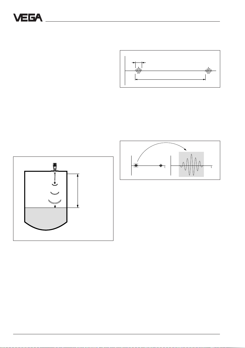
VEGAPULS radar sensors are used for noncontact and continuous distance
measurement. The measured distance
corresponds to a filling height and is
provided as level.
Product description - Function
1 ns
278 ns
Meas. principle:
emission – reflection – receipt
Smallest 5,8 GHz radar signals are emitted
from the antenna of the radar sensor as short
pulses. The radar impulses reflected by the
sensor environment and the product are
received by the antenna as radar echoes.
The running period of the radar impulses
from emission to receipt is proportional to the
distance and hence to the level.
Meas.
distance
emission - reflection - receipt
The radar impulses are emitted by the
antenna system as impulse packets with a
pulse duration of 1 ns and pulse breaks of
278 ns; this corresponds to a pulse package
frequency of 3,6 MHz. In the impulse breaks
the antenna system operates as receiver. Signal running periods of less than one millionth
of a second must be processed and the
echo pictures must be evaluated in a fraction
of a second.
Pulse sequence
VEGAPULS radar sensors can reach this in a
special procedure of time transformation
which spreads more than 3,6 million echo
pictures per second in a slow-motion picture,
then freezes and processes them.
Time transformation
Hence it is possible for the VEGAPULS 50
radar sensors to process the slow-motion
pictures of the sensor environment precisely
and in detail in cycles of 0,5 to 1 second
without using very time consuming frequency
analysis (e.g. FMCW) necessary for other
radar principles.
Virtually all products can be measured
Radar signals physically react similar to
visible light. According to the quantum theory
they penetrate empty space. Hence they are
not bound such as e.g. sound to conductive
product (air) and spread like light with light
velocity.
4 VEGAPULS 51 V … 54 V
Page 5
Product description - Function
Radar signals react to two electrical primary
quantities:
- the electrical conductivity of a substance.
- the dielectric constant of a substance.
All products which are electrically conductive
reflect radar signals very well. Even only
slightly conductive products ensure a
sufficient reflection for a reliable
measurement.
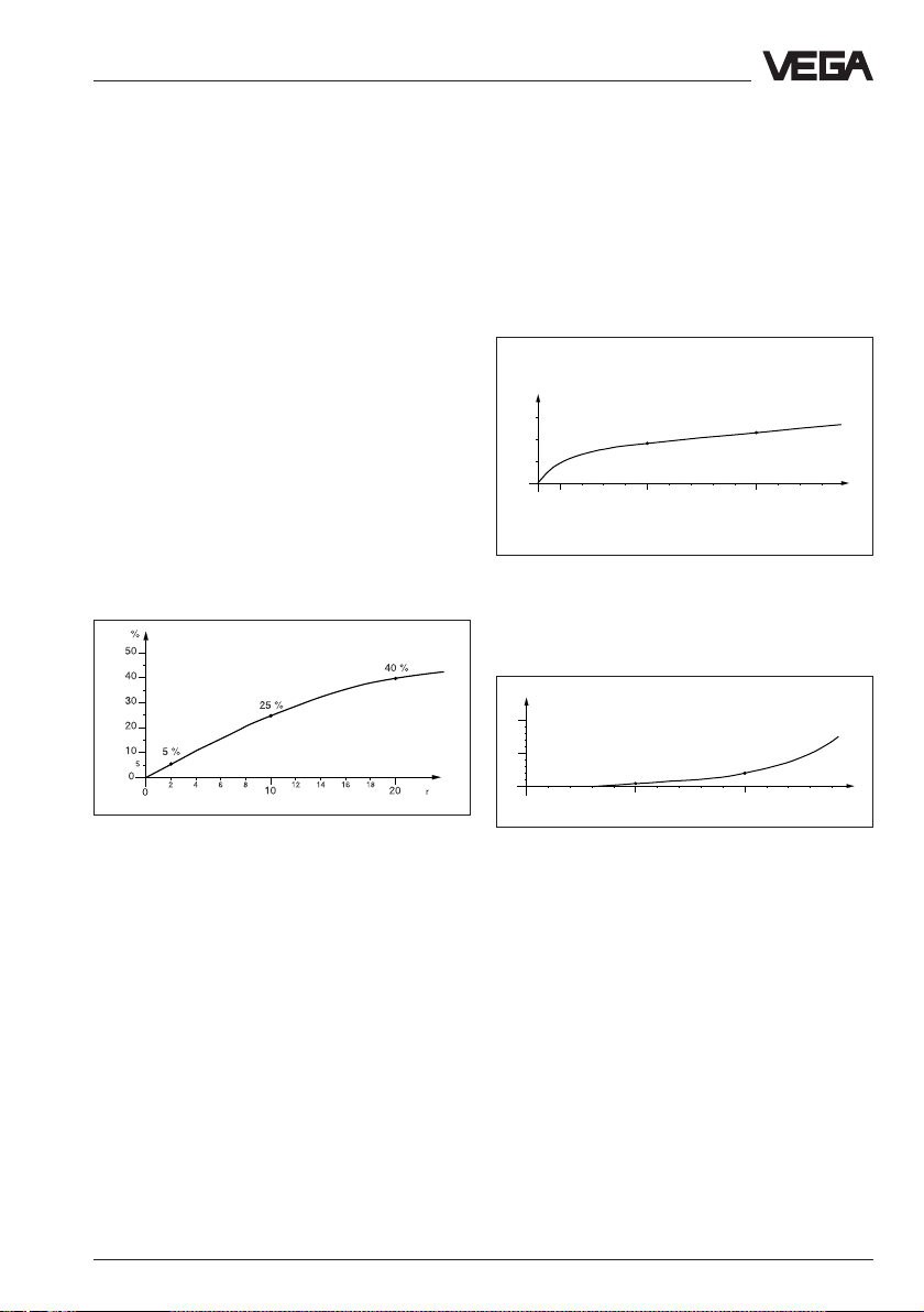
All products with a dielectric constant figure ε
of more than 2,0 reflect radar impulses
sufficiently (note: air has a dielectric constand
figure ε
The signal reflection increases with the
of 1).
r
conductivity or with the dielectric constant
figure of the product. Hence virtually all
products can be measured.
ε
Reflected radar power dependent on the
dielectric constant figure of the measured
product
Continuous and reliable
Unaffected by temperature, pressure and
individual gas atmospheres, VEGAPULS
radar sensors are used for quick and reliable
continuous level measurement of various
products.
%
0,03
r
0,02
0,01
0
100 500 1000 1300 °C
0
0,018 %
Temperature influence: Temperatur error
absolutely zero (e.g. at 500°C 0,018 %)
%
10
5
0
10
0
0,8 %
20 30 40 60
50
Pressure influence: Error with pressure
increase very low (e.g. at 50 bar 0,8 %)
0,023 %
3 %
70 80 90 110 120 130 140
100
bar
Due to the standard flanges from DN 50 to
DN 250, ANSI 2" to ANSI 10" or G 11/2 A and
11/2" NPT the sensor antenna systems are
adapted to the various measured products
and measurement environments.
VEGAPULS 50 enable level measurement
with radar sensors on systems where radar
sensors had not been used before due to
price reasons.
High-quality materials withstand also
extremely chemical and physical conditions.
The sensors deliver reliably, precisely and
longterm stable, reproducible analogue or digital level signals.
VEGAPULS 51 V … 54 V 5
Page 6
Product description
1.2 Application features
Applications
• Level measurement of liquids, limited use in
solids
• Measurement also in vacuum
• All slightly conductive materials and all
substances with a dielectric constant figure
εr > 2,0 can be measured
• Measuring ranges 0 … 20 m
Two-wire technology
• Supply and output signal on one two-wire
line
• Output signal and signal processing
completely digital, hence maximum
accuracy
Rugged and abrasionproof
• Non-contact
• High resistance materials: PTFE, 1.4571
Exact and reliable
• Resolution 1 mm
• Unaffected by noise, vapours, dusts, gas
compositions and inert gas layering
• Unaffected by varying density and
temperature of the product
• Measurement of pressures up to 40 bar
and product temperatures up to 200°C
Communicative
• Individually connectable, with 15 sensors
on one two-wire line (digital output signal)
• Integral indication of measured values
• Optionally indication separated from the
sensor
• Connection to all BUS-systems: Interbus S,
Modbus, Siemens 3964R, Profibus DP,
Profibus FMS, ASCII
• Adjustment from the DCS-stage
Ex-approvals
• CENELEC, FM, CSA, ABS, LRS, GL, LR
1.3 Adjustment
Each measuring distance is different, hence
each radar sensor must be given some
basic information on the application and the
environment.
The adjustment and parameter adjustment of
the radar sensors is hence carried out with
- the PC and adjustment program VVO
- the detachable adjustment module
MINICOM
- the signal conditioning instrument
VEGAMET
Adjustment with PC
The set-up and adjustment of the radar
sensors is generally made on PC with
adjustment program VVO (VEGA Visual Ope-
rating) under Windows®.
The program leads quickly through the
adjustment and parameter adjustment via
pictures, graphics and process
visualisations.
2
2
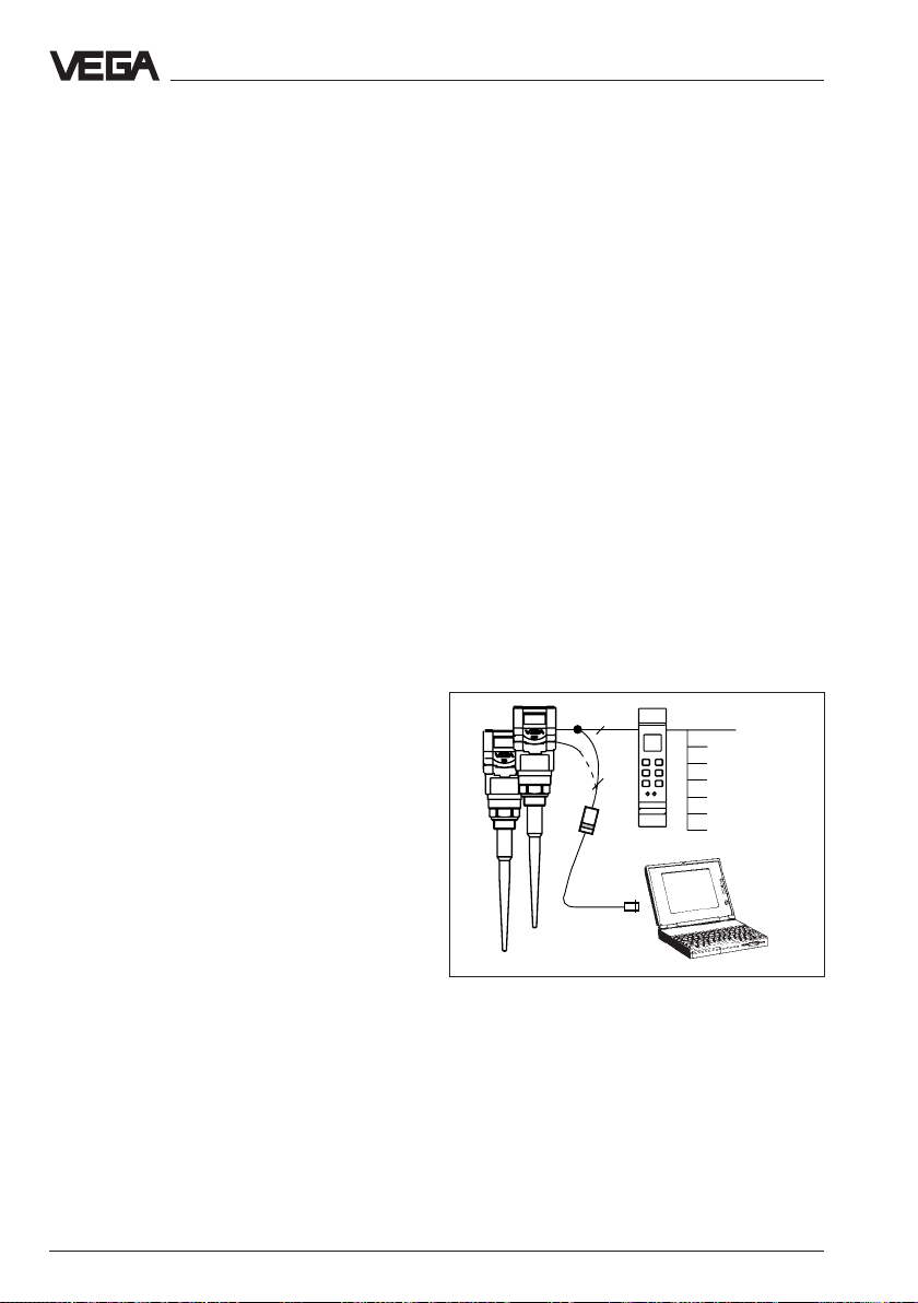
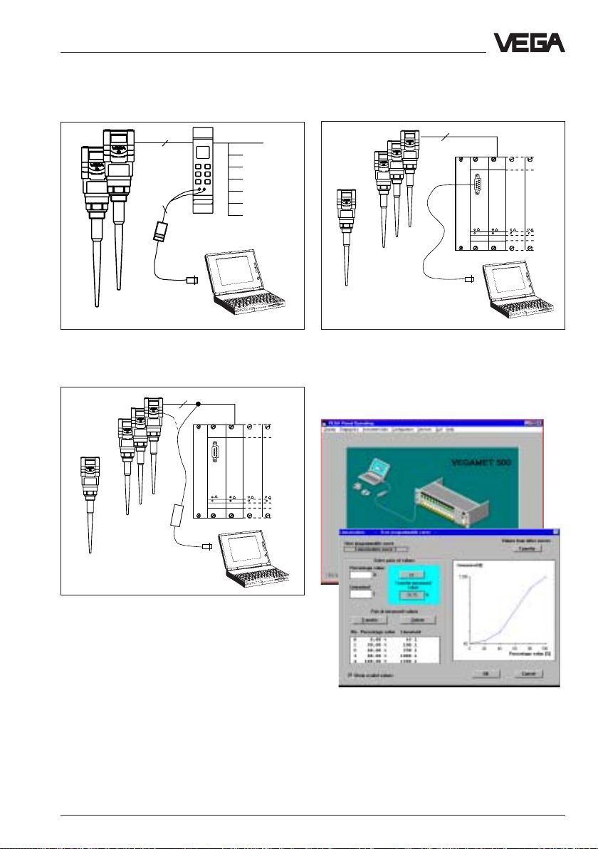
Adjustment with the PC on the digital signal
and supply line between the sensors and the
signal conditioning instrument VEGAMET
The PC can be connected to any individual
position of the system or the signal line. It is
hence connected with the two-wire PCinterface converter VEGACONNECT 2 to the
sensor, to the signal line or to the signal
conditioning instrument.
6 VEGAPULS 51 V … 54 V
Page 7
Product description - Adjustment
2
2
One or two sensors on the signal
conditioning instrument; adjustment with the
PC on the signal conditioning instrument
2
……
VEGALOG
VEGALOG
571 CPU
571 EA
1 … 15
2
……
VEGALOG
VEGALOG
571 CPU
571 EA
1 … 15
Adjustment with the PC and the standard
cable RS 232 directly on the processing
system
If required the adjustments can then be
quickly transferred to other sensors.
1…15 sensors on the processing system
VEGALOG. Adjustment with the PC on the digital signal and supply line to the processing
system or directly on the sensor
With the standard cable (RS232) the PC is
directly connected to the processing system
VEGALOG.
The adjustment and parameter adjustment
Automatic sensor recognition (top figure) and
visualized input, e.g. of a vessel linearisation
curve (bottom figure)
data can be at any time saved on the PC and
protected by passwords by means of the
adjustment software.
VEGAPULS 51 V … 54 V 7
Page 8
ESC
OK
-
+
1
2
on
100
%
CONNECT
514 Ex
Product description - Adjustment
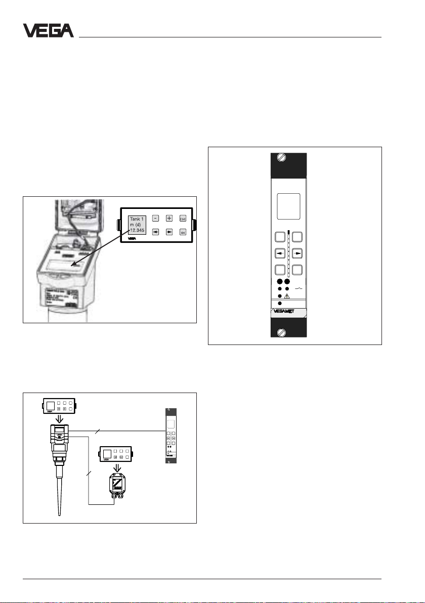
Adjustment with adjustment module
MINICOM
The adjustment with the small
(3,2 cm x 6,7 cm) 6-key adjustment module
with display can be compared with the
adjustment with the signal conditioning
instrument. You can carry out some sensor
relevant adjustments directly at the meas.
point which can naturally also be carried out
with the signal conditioning instrument.
Detachable adjustment module MINICOM
The adjustment module can be plugged into
or removed from the radar sensor or the
optionally external indicating instrument.
ESC
+
Tank 1
-
m (d)
12.345
OK
2
ESC
+
Tank 1
-
m (d)
12.345
OK
4
Adjustment with signal conditioning
instrument VEGAMET
Beside the PC the radar sensors with digital
output signal can be also adjusted with the
signal conditioning instrument VEGAMET.
6-key adjustment field on the instrument front
of a signal conditioning instrument VEGAMET
For adjustment the digital signal conditioning
instruments VEGAMET 514 V and 515 V are
provided with a 6-key adjustment field with
%
100
+
-
OK
ESC
CONNECT
on
513
display. Here you can carry out the
parameter adjustment in clear text.
The adjustment structure corresponds to the
adjustment on the adjustment module
MINICOM.
Adjustment with the detachable adjustment
module on the radar sensor or on the
external indicating instrument VEGADIS 10.
8 VEGAPULS 51 V … 54 V
Page 9
Types and versions
2 Types and versions
VEGAPULS series 50 sensors are a new
developed generation of very compact, small
radar sensors. With only very narrow space
requirements they are developed for short
meas. distances (0 … 20 m) and for
standard applications such as storage tanks
and buffer tanks.
Due to the small housing dimensions and
process connections, the compact sensors
monitor your levels very price favourably.
With the integral indication and the many
features of the "big brothers" of VEGAPULS
series 64 and especially of VEGAPULS
series 81, they open the advantages of a
radar level measurement for applications in
which the special adavantages of radar were
not possible, due to price reasons.
VEGAPULS 50 radar sensors dominate the
two-wire technology perfectly. They are the
first radar sensors transmitting supply
voltage and output signal via one two-wire
line. As output or meas. signal they provide a
digital output signal.
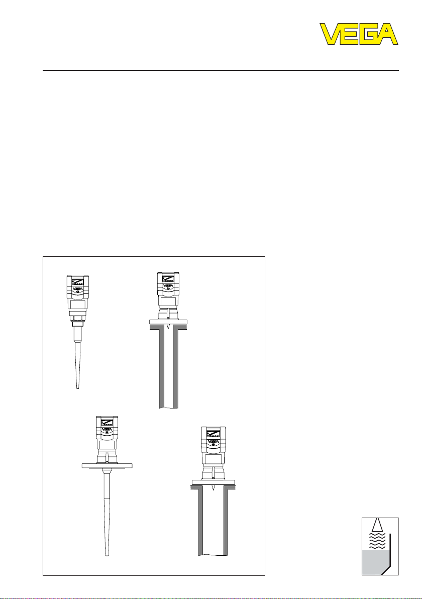
2.1 Type survey
The antenna is the eye of the radar sensor.
Four antenna systems are available for different applications and process requirements.
Each system differs in the physical features.
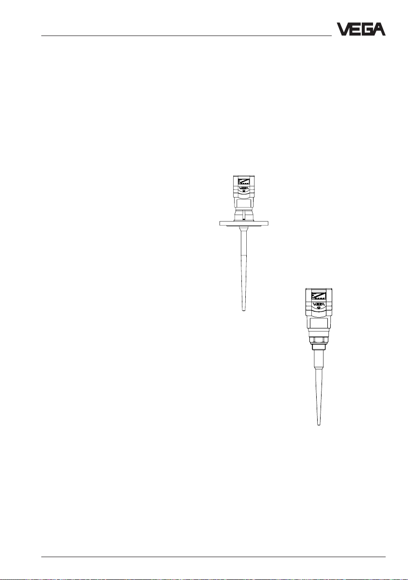
Rod antenna
Rod antennas with high
chemical resistance require
smallest flange dimensions
(DN 50). The antenna rod and
the wetted flange parts are
made of PTFE, PP or PPS so
that the rod antenna can be
easily cleaned and is
insensitive to condensation.
The rod antenna is suitable for
pressures up to 16 bar and
temperatures up to 150°C.
VEGAPULS 53
VEGAPULS 51/52
VEGAPULS 51 V … 54 V 9
Page 10
Types and versions - Survey
Horn antenna
VEGAPULS 54
Horn antennas are best
suited for most applications.
They focus the radar signals
very well. Manufactured of
1.4571 (stst) they are very
rugged and physically as well
as chemically resistant. They
are suitable for pressures up
to 40 bar and for product
temperatures up to 150°C.
VEGAPULS 54
(pipe antenna/
standpipe)
Pipe antenna
VEGAPULS 54
(pipe antenna/
standpipe)
Pipe antennas on surge or
bypass pipes only form a
complete antenna system in
conjunction with a measuring
pipe which can also be bent.
Pipe antennas are especially
suitable for products with
heavy product movements or
products with low dielectric
constant figure.
The antenna can be with or
without horn. Versions with
horn characterize by very
good antenna gain. A very
good reliability can be
achieved even in case of
products with very bad
reflection features.
The meas. pipe means a
conductor for radar signals.
The running period of the
radar signals changes in the
pipe and depends on the
pipe diameter. The pipe inner
diameter must be
programmed in the
electronics so that the running
period can be compensated.
VEGAPULS 54 without horn
(pipe antenna/standpipe)
10 VEGAPULS 51 V … 54 V
Page 11
Types and versions - Survey
Survey of features
• Application preferably of liquids in storage
tanks or vessels
• Meas. range 0 …20 m
• Ex-approved in IEC or ATEX
classification EEx ia [ia] IIC T 6
• Integral measured value indication
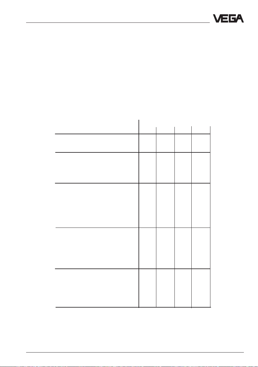
Survey
51 V 52 V 53 V 54 V
VEGAPULS …
Signal output
digital meas. signal • • • •
Voltage supply
– two-wire technology (voltage
supply and signal output
via one two-wire line) • • • •
Process connection
– G11/2 A; 11/2" NPT • • – –
– DN 50; ANSI 2" – – • •
– DN 80; ANSI 3" – – • •
– DN 100; ANSI 4" – – • •
– DN 150; ANSI 6" – – – •
Adjustment
– with PC • • • •
– with adjustment module in sensor • • • •
– with adjustment module in external
indicating instrument • • • •
– with signal conditioning instrument • • • •
Antenna material
– PP • – – –
– PPS/StSt • – – –
– PTFE/StSt – • – –
– PTFE – – • –
– StSt – – – •
VEGAPULS 51 V … 54 V 11
Page 12
Types and versions - Survey
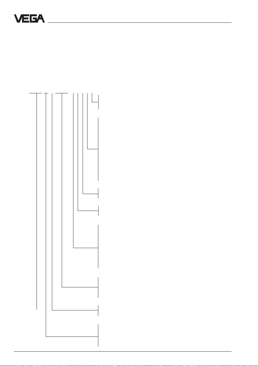
Type code
The second figure of the type designation,
e.g. VEGAPULS 5[1]… differentiates the
instruments acc. to process connection and
antenna material.
VEGAPULS 51 V EXXX X X X X X
1 for measurement in standpipe (d = 50 mm)
3 for socket lengths up to 100 mm
9 for socket lengths up to 250 mm
G - Process connection G 11/2 A
N - Process connection 11/2 NPT
K - Process connection DN 50 PN 16
L - Process connection DN 80 PN 16
E - Process connection DN 100 PN 16
F - Process connection DN 150 PN 16
S - Process connection ANSI 2" 150 PSI
W - Process connection ANSI 3" 150 PSI
P - Process connection ANSI 4" 150 PSI
V - Process connection ANSI 6" 150 PSI
Y - other process connections
X - without indication
A - with integral indication
X - without MINICOM adjustment module
B - with MINICOM adjustment module (pluggable)
A - 20 … 72 V DC; 20 … 250 V AC; 4 … 20 mA
B - 20 … 72 V DC; 20 … 250 V AC; 4 … 20 mA; HART
C - Two-wire (loop powered); 4 … 20 mA
D - Two-wire (loop powered); 4 … 20 mA; HART
E - Supply via signal conditioning instrument
P - 90 … 250 V AC (only in USA)
N - 20 … 36 V DC, 24 V AC (only in USA)
Z - Supply via signal conditioning instrument (only in USA)
The letter e.g. VEGAPULS 51[V]
characterizes the output signal:
V stands for a digitial output signal (VBUS), K
stands for an analogue 4 … 20 mA output
signal (compact instrument).
®
®
.X - FTZ approval (BRD)
EX.X - Ex approved CENELEC EEx ia IIC T6, FTZ
.U - FCC approval (US)
EX.U - FM, CLASS 1, DIV 1; FCC (US)
K - Analogue 0 … 20 mA output signal
PULS V - Digital output signal (two-wire technology)
for radar
Type 51: 1 1/2 PP or PPS/StSt rod antenna
Type 52: 1 1/2 PTFE or PTFE/StSt rod antenna
Type 53: DN 50 … DN 150 PTFE rod antenna
Type 54: DN 50 … DN 100 for mounting on standpipe
12 VEGAPULS 51 V … 54 V
Page 13

Types and versions - Configuration of meas. systems
2.2 Configuration of measuring systems
Which radar sensor you use depends on
your process requirements and installation
conditions as well as on the requirements of
your control or processing system.
On sensors with digital output signal like
VEGAPULS 51 V … 54 V a meas. system
consists of a sensor and a processing unit.
The processing unit (the signal conditioning
instrument VEGAMET or the processing
system VEGALOG) evaluates the level proportional digital meas. signal in a number of
routines and provides then the levels as
individual current, voltage or switching
signals.
On the following pages you find the various
instrument configurations which are called in
the following meas. system and which are
partly shown with a signal processing.
• 2 sensors on one two-wire line
(page 14)
• 2 sensors in Ex on one two-wire line
(page 15)
• 15 sensors on one two-wire line
(page 16)
• 3 sensors in Ex on one two-wire line
(page 17)
Ex
Series 50 sensors require for operation in Exareas Ex-separator VEGATRENN 548 V Ex,
providing intrinsically safe Ex-circuits to the
sensors.
On the Ex-separtor VEGATRENN 548 V up to
9 sensors can be connected in groups with
three sensors each (see page 17).
Note to page 15…17:
2)
Sensor lines should be looped in screened cables.
It is recommended to earth the cable screens on
both ends. However it must be noted that no earth
compensation currents flow over the screen. Earth
compensation currents are avoided in case of
earthing on both ends by connecting the cable
screen on one earth side (e.g. in the switching
cabinet) via a capacitor (e.g. 1 µF; 100 V) with the
earth potential.
Sensor lines leading to the same separator card,
can be looped together in one screened multiple
wire cable.
Sensor lines leading to other separator cards must
be looped in separate screened cables.
VEGAPULS 51 V … 54 V 13
Page 14
Types and versions - Configuration of meas. systems
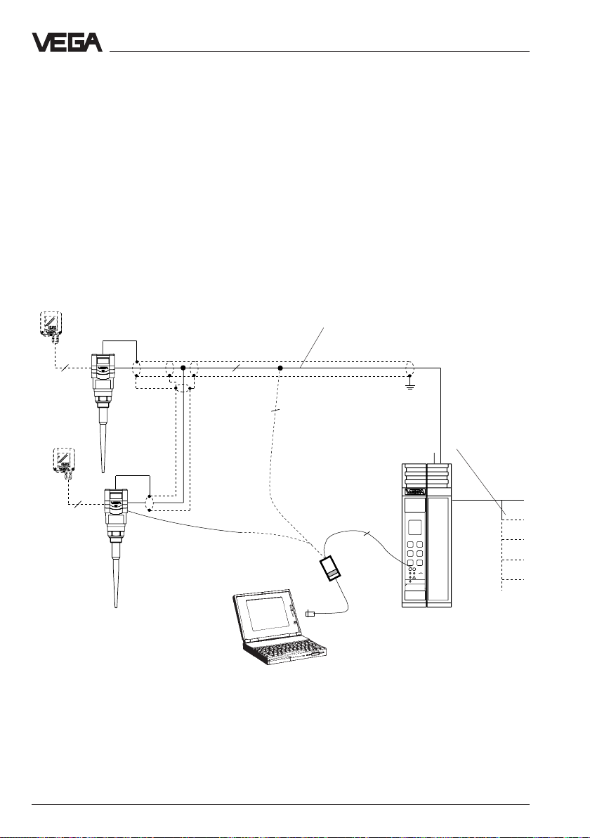
1 … 2 sensors on the signal conditioning instrument VEGAMET 515 V
• Two-wire technology, supply from the signal conditioning instrument.
Output signals and supply voltage via a two-wire line.
• Digital output signal, two sensors on one line.
• Measured value indication in the sensor and in the signal conditioning
instrument.
• Optionally external indicating instrument
(can be mounted up to 25 m separated from the sensor in Ex-area).
• Adjustment with PC, the signal conditioning instrument or the
adjustment module (can be plugged in the sensor or in the external
indicating instrument)
• Max. resistance of the signal line 15 Ω per wire or 1000 m cable length
VEGADIS 50
Screened line in case of
electromagnetic interferences
1)
4
VEGADIS
10/50
2
2
Current outputs
Voltage outputs
Relay
Digital wiring
Fault signals
4
2
VEGACONNECT 2
VEGAMET
515V
Signal conditioning
instrument VEGAMET 515 V
in housing type 505
1) Sensor lines should be looped in screened
cables. It is recommended to earth the cable
Processings see product information "Signal
conditioning instruments series 500"
screens on both ends. However it must be
noted that no earth compensation currents
flow over the screen. Earth compensation
currents are avoided in case of earthing on
both ends by connecting the cable screen on
one earth side (e.g. in the switching cabinet)
via a capacitor (e.g. 1 µF; 100 V) with the
earth potential.
14 VEGAPULS 51 V … 54 V
Page 15
Types and versions - Configuration of meas. systems
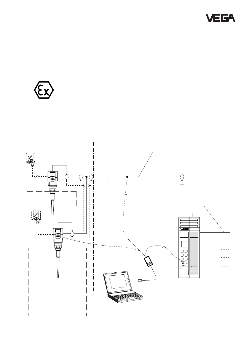
1 … 2 sensors in Ex-area via separator
VEGA TRENN 548 V Ex on signal conditioning instrument VEGAMET 515 V
• Two-wire technology, supply from separator.
Output signals and voltage supply via one two-wire line
• Ex-area acc. to CENELEC and ATEX
• Digital output signal, two sensors on one line
• Meas. value indication in the sensor or in the signal conditioning
instrument
• Optionally external indicating instrument
(can be mounted up to 25 m separated from the sensor in Ex-area)
• Adjustment with PC, signal conditioning instrument or adjustment
module (can be plugged in the sensor or in the external indicating
instrument)
• Max. resistance of the signal line 15 Ω per wire or 1000 m cable length
(see also approval certificates of the separators)
VEGADIS 50
4
Ex-area
Zone 1
or
Zone 0
4
Zone 1 or Zone 0
Not Ex-area
2
2
VEGACONNECT 2
Screened line in case of electromagnetic
interferences
2) see note on page 13
Current outputs
Voltage outputs
Relays
Digital wiring
Fault signals
2
VEGAMET
VEGATRENN
515V
547
Signal conditioning instrument VEGAMET
515 V with Ex-separator VEGATRENN
548 V Ex in housing type 506
Processings see product information "Signal
conditioning instruments series 500"
VEGAPULS 51 V … 54 V 15
Page 16
Types and versions - Configuration of meas. systems
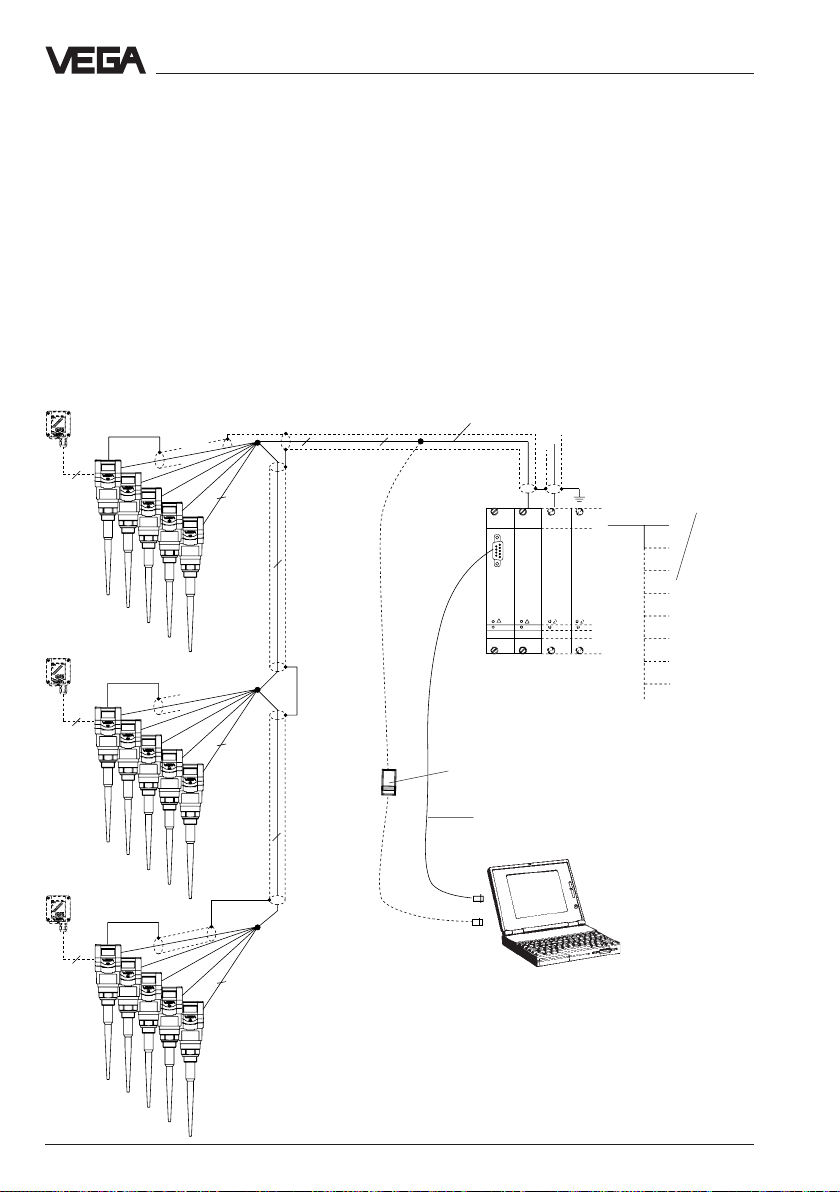
15 sensors via one two-wire line on the processing system VEGALOG 571
• Two-wire technology, voltage supply and digital output signals via one
two-wire line from the processing system VEGALOG 571.
• Up to 15 sensors on one two-wire line
• Meas. value indication integrated in the sensor
• Optionally external indicating instrument (can be mounted up to 25 m
separated from the sensor in Ex-area).
• Adjustment with PC or adjustment module (pluggable in sensor or in
external indicating instrument)
• Max. resistance of the signal line 15 Ω per wire or 1000 m cable length.
4
VEGADIS 50
4
4
Screened line in case of electromagnetic
2
2
2
2
2
interferences
1)
2
CPU
VEGALOG
571 CPU
Processing system VEGALOG 571
with input cards in 19"-rack. 15
sensors on one module card and
two-wire line
VEGACONNECT 2
Interface cable
RS 232
VEGALOG
571 EV
Processings see product information
"Signal conditioning instruments
series 500"
Current outputs
Voltage outputs
Relays
Digital wiring
Fault signals
Connection to all
Bus-systems
Transistor outputs
2
1) Sensor lines should be looped in screened cables.
It is recommended to earth the cable screens on
both ends. However it must be noted that no earth
compensation currents flow over the screen. Earth
VEGAPULS 51 … 53
(15 sensors per two-wire line,
individual grouping)
compensation currents are avoided in case of
earthing on both ends by connecting the cable
screen on one earth side (e.g. in the switching
cabinet) via a capacitor (e.g. 1 µF; 100 V) with the
earth potential.
16 VEGAPULS 51 V … 54 V
Page 17

Types and versions - Configuration of meas. systems
3 sensors per two-wire line via
separator VEGATRENN 548 V Ex on the processing system VEGALOG 571
• Two-wire technology, voltage supply and digital output signals via one
two-wire line from the separator
• Three sensors on one two-wire line
• Meas. value indication integrated in the sensor
• Optionally external indicating instrument (can be mounted up to 25 m
separated from the sensor in Ex-area).
• Adjustment with PC or adjustment module (pluggable in the sensor or in
external indication instrument)
• Max. resistance of the signal line 7,5 Ω per wire or 1000 m cable length
(see approval certificates of the separators).
Ex-area Not Ex-area
VEGADIS 50
2
2
2
2
Screened line in case of electromagnetic
interferences
2
2
2
2
2
2
2
2
2
CPU
VEGALOG
VEGALOG
571 CPU
2) see note page 13
Processing system
VEGALOG 571
(19" module card)
VEGATRENN
VEGATRENN
571 EV
VEGATRENN
548
548
VEGALOG
VEGATRENN
VEGATRENN
571 EV
548
548
Current and voltage
outputs
Digital wiring
Fault signals
Transistor outputs
Relays, connection to
all Bus-systems
548
Separator VEGATRENN 548 V Ex
22
2
(max. 9 sensors per card)
Input card of VEGALOG 571
(max. 15 sensors per card)
VEGACONNECT 2
Interface cable RS 232
2
2
VEGAPULS 51 … 53
3 sensors per two-wire line,
individual grouping
VEGAPULS 51 V … 54 V 17
Page 18

Technical data
3 Technical data
3.1 Data
Power supply
Supply voltage from signal conditioning instrument VEGAMET or
Current consumption max 22,5 mA
Power consumption max. 80 mW 0,45 VA
processing system VEGALOG 571
(max. 36 V DC)
fuse 0,5 A (slow-blow)
Meas. range
1)
Standard 0 … 20 m
Measurement in standpipe
- VEGAPULS 54 on DN 50 0 … 16 m
- VEGAPULS 54 on DN 100 0 … 19 m
Output signal (see "Outputs and processings")
Digital meas. signal (VBUS)
Adjustment
- PC with adjustment software VEGA Visual Operating
- adjustment module MINICOM
Accuracy (typical values under reference conditions)
2)
Linearity error < 0,1 % (relating to max. meas. range)
Average temperature error 0,03 %/10 K
Accuracy of the 4 … 20 mA 0,25 %
output signal
Resolution 1 mm
Characateristics
Meas. frequency 5,8 GHz (USA 6,3 GHz)
Meas. intervals 1 s
Min. span between
full and empty adjustment > 10 mm (recommended >50 mm)
Beam angle (at –3 dB)
- VEGAPULS 51 … 53 < 24°
- VEGAPULS 54 with DN 80 38°
- VEGAPULS 54 with DN 100 30°
- VEGAPULS 54 with DN 150 20°
1)
Min. distance of the antenna to the medium 5 cm
18 VEGAPULS 51 V … 54 V
2)
Reference conditions acc. to IEC 770:
e.g. temperature 18 … 30°C
Page 19
Technical data
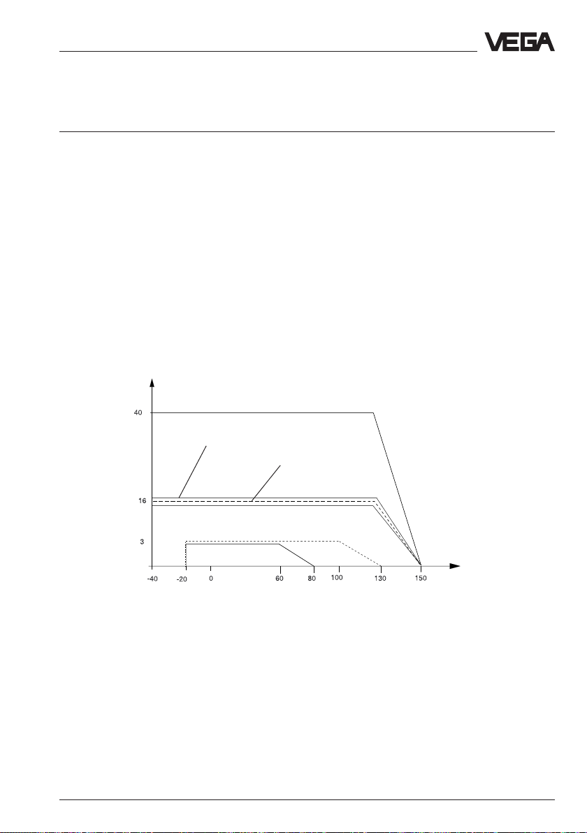
Ambient conditions
Vessel pressure
- VEGAPULS 51 (process connection PVDF) -1 … 3 bar
- VEGAPULS 51 (process connection StSt) -1 … 16 bar
- VEGAPULS 52 (process connection PVDF) -1 … 3 bar
- VEGAPULS 52 (process connection StSt) -1 … 16 bar
- VEGAPULS 53 -1 … 16 bar
- VEGAPULS 54 -1 … 40 bar
Ambient temperature on the housing -20°C … +60°C
Flange temperature (process temperature)
- VEGAPULS 51 (process connection PVDF) -20°C … +80°C
- VEGAPULS 51 (process connection StSt) -40°C … +150°C
- VEGAPULS 52 (process connection PVDF) -20°C … +120°C
(shortterm 130°C)
- VEGAPULS 52 (process connection StSt) -40°C … +150°C
- VEGAPULS 53 (process connection StSt) -40°C … +150°C
- VEGAPULS 54 (process connection StSt) -40°C … +150°C
Diagram of the flange temperature dependent on the process pressure
bar
Type 54
Type 53
Type 52 with
StSt process
connection
Type 51 with
StSt process connection
Type
51
Type
52
°C
Storage and transport temperature -40°C … +80°C
Protection IP 66/67
Protection class
- two-wire sensor II
- four-wire sensor I
Overvoltage category III
VEGAPULS 51 V … 54 V 19
Page 20

Technical data
Ex-technical data (note approval documents)
Flame proofing ia (intrinsically safe in conjunction with
a safety barrier or separator)
Classification EEx ia IIC T6
Perm. housing ambient temperature T6: 45°C T5: 58°C T4/T3: 60°C
Temperature class (permissible ambient temperature on the antenna system)
- T6 80°C
- T5 95°C; type 51: 80°C
- T4 130°C; type 51: 80°C
- T3 150°C; type 51: 80°C; type 52: 130°C
Ex-approved in category or zone
- EC-type approval Type 5*V Ex: Zone 1 (II 2 G)
Type 5*V Ex 0: Zone 0 (II 1 G)
- conformity certificate Type 5*V Ex: Zone 1
Type 5*V Ex 0: Zone 0
Process connections
VEGAPULS 51, 52 G 11/2 A, 11/2" NPT (rod antennas on plastic
or StSt thread)
VEGAPULS 53 DN 50, DN 80, DN 100, DN 150 (rod antennas)
VEGAPULS 54 DN 50, DN 80, DN 100, DN150
ANSI 2", 3", 4" and 6"
(up to DN 100 or 4" mounting on surge pipe)
Connection lines
Two-wire sensors, supply and signal via one two-wire line
Line resistance max. 15 Ω per wire or 1000 m cable length
Cross-section area of conductor generally 2,5 mm
Earth connection max. 4 mm
2
2
Cable entry 2 x M20 x 1,5 (cable diameter 5 … 9 mm)
Materials
Housing PBT (Valox)
Flange / process connection
- VEGAPULS 51 PVDF or StSt
- VEGAPULS 52 PVDF or StSt
- VEGAPULS 53, 54 1.4571
Antenna
- VEGAPULS 51 PP or StSt / PPS
- VEGAPULS 52 PTFE or StSt / PTFE
- VEGAPULS 53 PTFE
- VEGAPULS 54 1.4571, 1.4071
Flange coating (only VEGAPULS 53) PTFE
20 VEGAPULS 51 V … 54 V
Page 21

Technical data
Weights
Dependent on the kind of process connection or the flange size
- Screw connection G 11/2 A, 11/2" NPT 1,3 kg
- DN 50 6 kg
- DN 80 8 kg
- DN 100 9,5 kg
- DN 150 13,5 kg
- ANSI 2" 5,8 kg
- ANSI 3" 7 kg
- ANSI 4" 11 kg
- ANSI 6" 15,5 kg
CE-conformity
VEGAPULS series 50 radar sensors meet the protective regulations of EMC (89/336/EWG)
and NSR (73/23/EWG) and R & TTE directive (1999/5/EC).
Conformity was judged acc. to the following standards:
EN 300 683-1: 1997
EN 300 440-1: 1995
I-ETS 300-440
Expert opinion No. 0043052-01/SEE, Notified Body No. 0499
EN 61 326: 1997/A1: 1998 (EMC Emission/Susceptibility)
EN 61 010 - 1: 1993 (NSR)
EN 50 020: 1994 (ATEX)
EN 50 018: 1994
EN 50 014: 1997
Outputs and processings
Display indication
Optionally mounted, scalable analogue and digital meas. value indication as well as
additionally up to 25 m separated from the sensor, meas. value indication powered by the
sensor.
Signal output
Signal output digital output signal in two-wire technology
Two-wire technology:
The digital output signal (meas. signal) is modulated to the power supply and processed in
the signal conditioning instrument or processing system.
VEGAPULS 51 V … 54 V 21
(VBUS)
Page 22
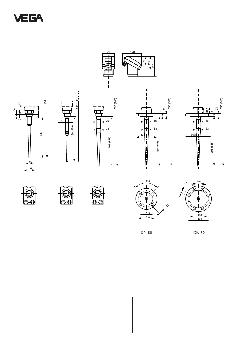
3.2 Dimensions
Technical data - Dimensions
∅
∅
G 11/2 A o.
11/2" NPT
thread
VEGAPULS 51
VEGAPULS 52
∅
G 11/2 A o.
11/2" NPT
thread
∅
∅
G 11/2 A o.
11/2" NPT
thread
Rod antennaRod antennaRod antenna
VEGAPULS 51 VEGAPULS 52
∅
∅
∅
∅
∅
∅
∅
∅
∅
∅
∅
∅
Rod antenna Rod antenna
VEGAPULS 53
Rod length max. socket length
VEGAPULS 51 330 50 mm
VEGAPULS 51 360 (option 510) 100 mm (option 250 mm)
VEGAPULS 52 330 50 mm
VEGAPULS 52 395 (option 545) 100 mm (option 250 mm)
VEGAPULS 53 395 (option 545) 100 mm (option 250 mm)
22 VEGAPULS 51 V … 54 V
Page 23
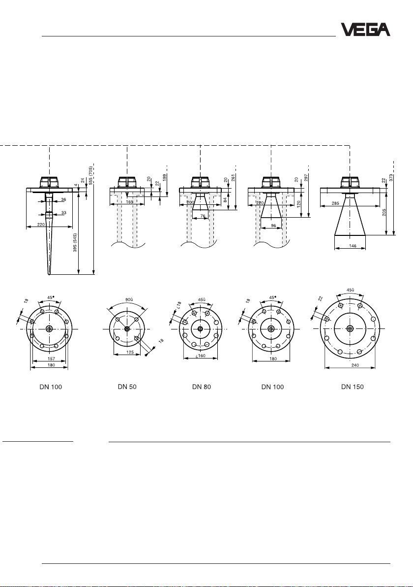
Technical data - Dimensions
∅
∅
∅
∅
∅
∅
∅
∅
∅
∅
∅
∅
∅
∅
∅
Rod antenna Pipe antenna Pipe antenna Pipe antenna
VEGAPULS 54
∅
∅
∅
∅#
Pipe antenna
(horn antenna)
VEGAPULS 51 V … 54 V 23
Page 24
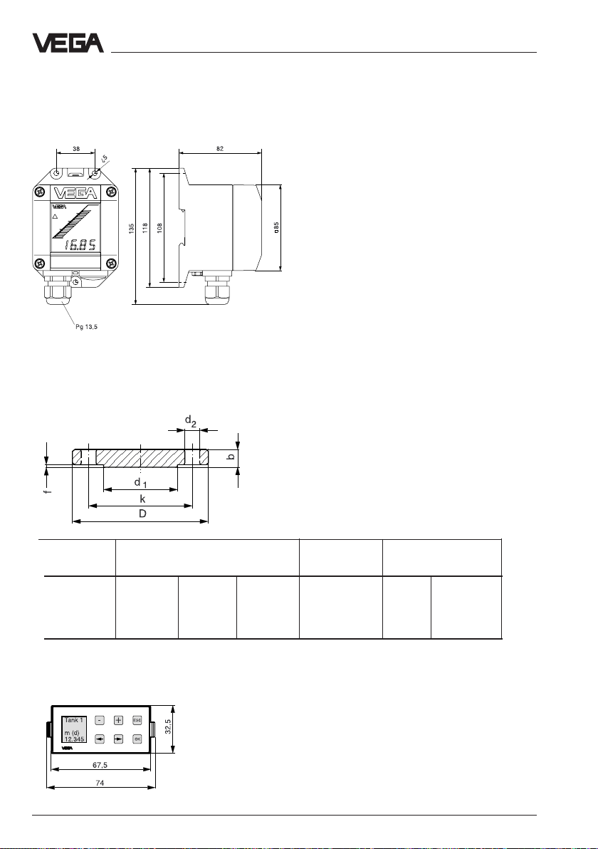
External indicating instrument VEGADIS 50
Mounting on carrier rail 35 x 7,5 acc. to EN 50 022 or flat
screwed
Flange dimensions acc. to ANSI
Technical data - Dimensions
Note:
Cable diameter of the connection cable min.
5 mm and max. 9 mm.
Otherwise the seal effect of the cable entry will
not be ensured.
D = outer flange diameter
b = flange strength
k = diameter of hole circle
d1= seal ledge diameter
f = seal ledge strength
1
/16" = ca. 1,6 mm
d2= diameter of holes
Size Flange Seal ledge Holes
Db k d1No. d
2
2" 150 psi 152,4 20,7 120,7 91,9 4 19,1
3" 150 psi 190,5 25,5 152,4 127,0 4 19,1
4" 150 psi 228,6 25,5 190,5 157,2 8 19,1
6" 150 psi 279,4 27,0 241,3 215,9 8 22,4
Adjustment module MINICOM
Adjustment module for insertion in series 50
sensors or into the external indicating
instrument VEGADIS 50
24 VEGAPULS 51 V … 54 V
Page 25

Technical data - Approvals
3.3 Approvals
When using radar sensors in Ex and St-Exareas, the instrument must be suitable and
approved for these explosion zones and
applications.
For the use on ships, special type approvals
are available.
The suitability is tested by the approval
authorities and certified by approval
documents.
VEGAPULS 51 V Ex (0) to 54 V Ex (0)
sensors must be supplied from one
intrinsically safe circuit when used in Exareas. This is ensured by the separators
VEGATRENN 548 V Ex.
The separator provides intrinsically safe (ia)
circuits.
The resistance of the signal line must not
exceed 15 Ω per wire.
VEGAPULS 51 V Ex … 54 V Ex sensors are
approved for Ex-Zone 1.
VEGAPULS 51 V Ex 0 … 54 V Ex 0 sensors
are approved for Ex-Zone 0.
Please note the attached approval
documents when you want to use a sensor in
Ex-environment.
Test and approval authorities
VEGAPULS radar sensors are tested and
approved by the following monitoring and
approval authorities:
- PTB
(Physikalisch Technische Bundesanstalt Physical Technical Approval Authority)
- FM
(Factory Mutual Research)
- ABS
(American Bureau of Shipping)
- LRS
(Lloyds Register of Shipping)
- GL
(German Lloyd)
- CSA
(Canadian Standards Association)
VEGAPULS 51 V … 54 V 25
Page 26
;;
;;
;;
;;
;;
;;
;;
;;
;;
;;
;;
;;
;;
;;
;;
;;
;;
;;
Mounting and installation - General installation instructions
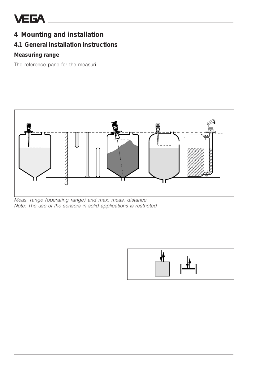
4 Mounting and installation
4.1 General installation instructions
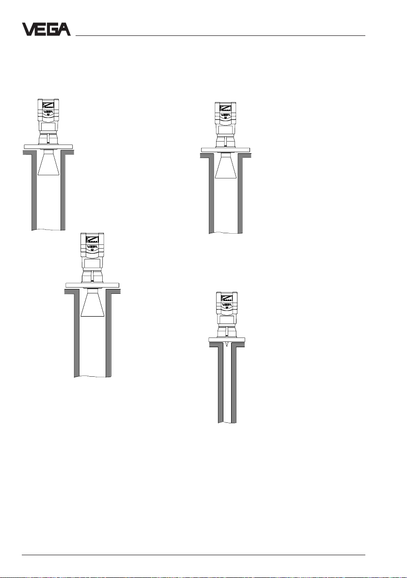
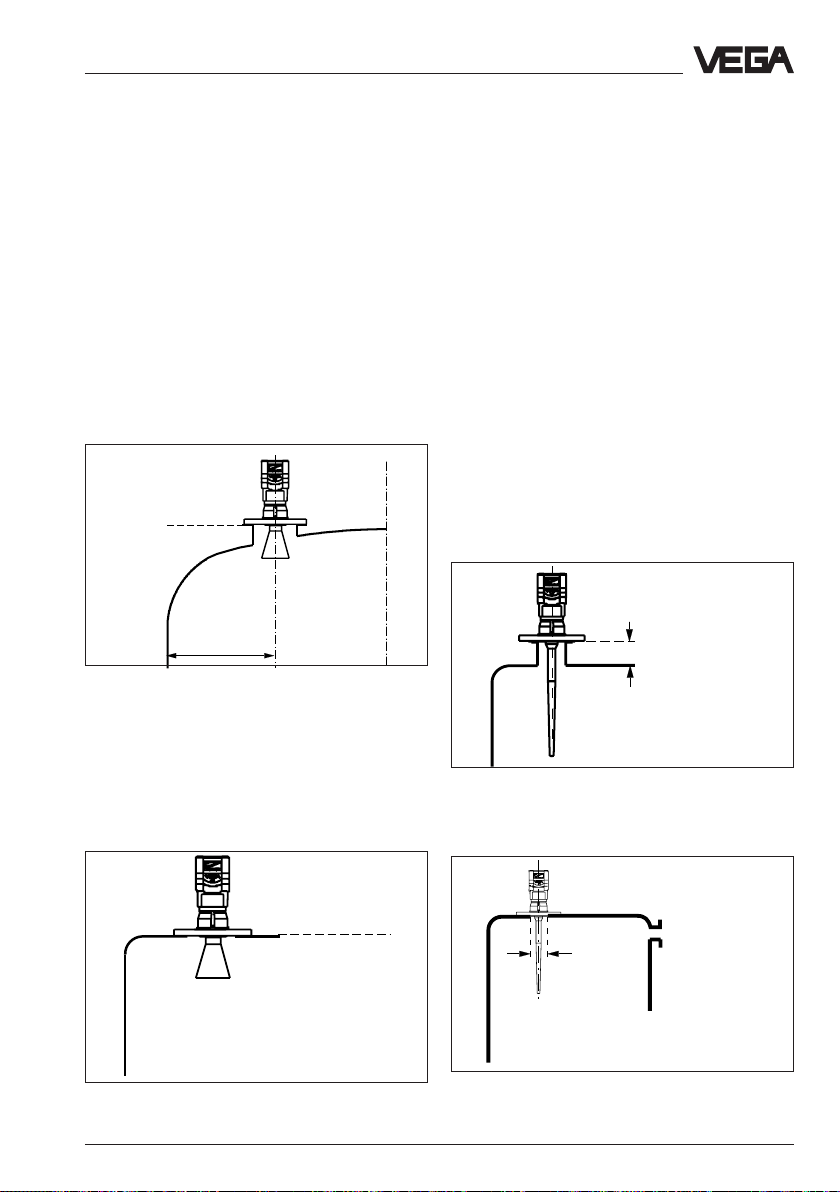
Measuring range
The reference pane for the measuring range
is the flange face (type 53/54) or the seal
shoulder of the thread (type 51/52). The max.
measuring range is 0 … 20 m, dependent on
the sensor type. The min. distance to the
medium must be 5 cm.
For measurements in surge or bypass pipes
(pipe antenna), the max. meas. distance is
reduced.
Note that for measurements where the
medium reaches the antenna, build-up on the
antenna is possible which can cause
measurement errors.
Type 53
Reference pane
Max.
Type 54
full
empty
Max.
Type 51/52 Type 54
Max.
Meas. range
max. meas. distance 20 m
Meas. range (operating range) and max. meas. distance
Note: The use of the sensors in solid applications is restricted
False reflections
Flat obstructions and struts cause large false
reflections. They reflect the radar signal with
high amplitude.
Round profile interfering surfaces have a diffuse reflection of the radar signals and cause
false reflections with low density. Hence they
are less critical than reflections from a flat
surface.
If flat obstructions in the range of the radar
signals cannot be avoided, it is
recommended to reflect the interfering
signals with a deflector.
26 VEGAPULS 51 V … 54 V
Profiles with smooth interfering surfaces
cause large false signals
Due to this scattering the interfering signals
will be low in amplitude and diffuse so that
they can be filtered out by the sensor.
Max.
Page 27
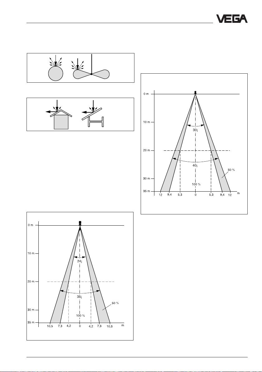
Mounting and installation - General installation instructions
This emission cone depends on the antenna
used.
Round profiles diffuse the radar signals
Meas. distance
A deflector causes signal scattering
Emission cone and false reflections
The radar signals are focused by the
antenna system. The signals leave the
antenna in conical form, similar to the beam
pattern of a spotlight.
DN 100 horn antenna
Series 50
Series 64
and 81
Meas. distance
Rod antenna
Series 50
Series 64
and 81
Emission cone of a DN 100 horn antenna
Emission cone of a rod antenna (independent
on the process connection)
VEGAPULS 51 V … 54 V 27
Page 28
If possible provide a "clear view" inside the
emission cone to the product and avoid
obstructions in the first third of the cone.
Optimum measuring conditions exist when
the emission cone reaches the measured
product vertically and when the emission
cone is free from obstructions.
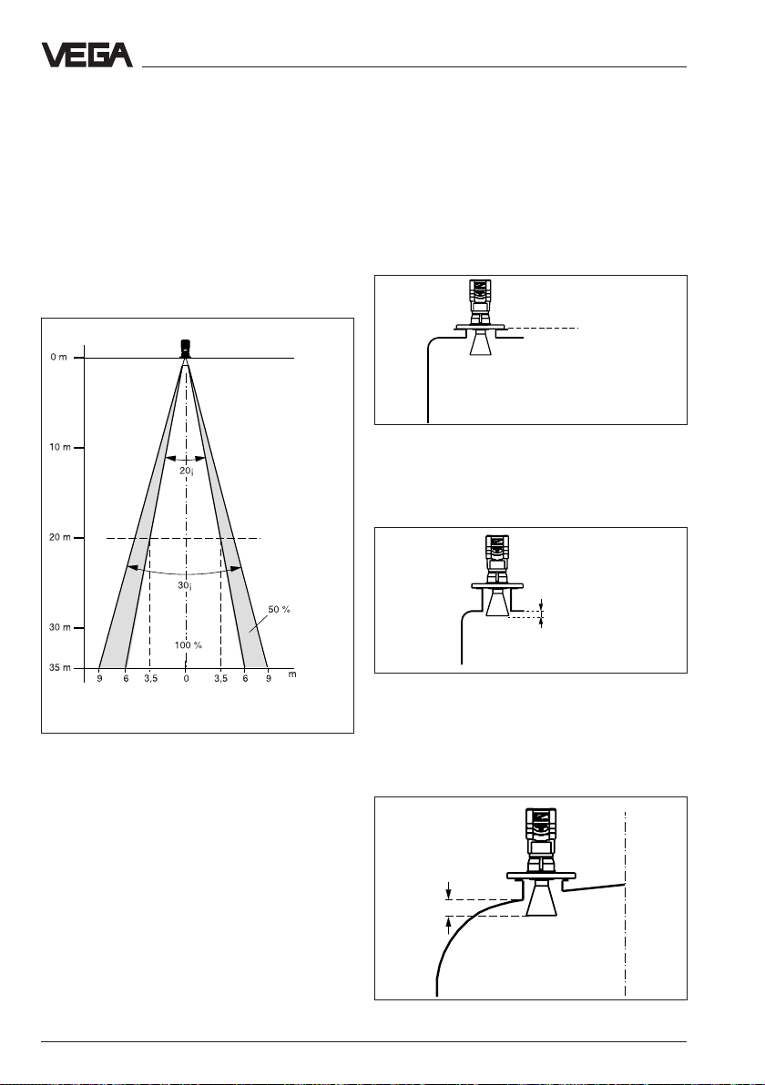
Mounting and installation - Measurement of liquids
4.2 Measurement of liquids
Horn antenna
Most of the time the mounting of radar
sensors is made on short DIN-socket pieces.
The instrument flange is the reference pane
of the measuring range. The antenna should
always protrude out of the flange pipe.
Meas. distance
DN 150 horn antenna
Series 50
Series
64
and 81
Emission cone of a DN 150 horn antenna
Reference pane
Mouning on short DIN-socket piece
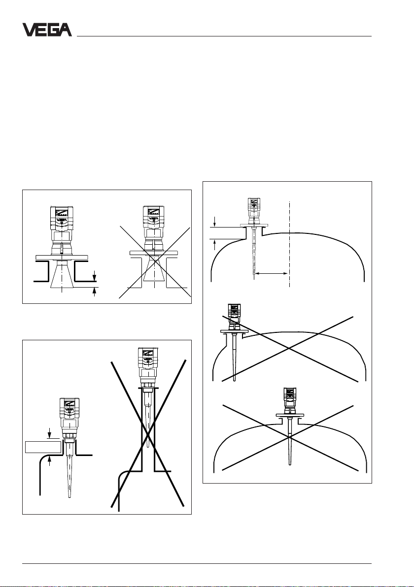
When the DIN-socket piece is longer, please
note that the horn antenna must protrude at
least 10 mm out of the socket.
> 10 mm
Mounting on longer DIN-socket
When mounting on dished end vessels the
antenna has to protrude at least 10 mm.
> 10 mm
Mounting on a dished end vessel
28 VEGAPULS 51 V … 54 V
Page 29
Mounting and installation - Measurement of liquids
Do not mount the transmitter in the centre of
the dished end of the tank or close to the
outer wall of the vessel, but approx. 1/2 vessel
radius from the middle or from the outer wall.
Dished tank ends can act as paraboloidal
reflectors. If the radar sensor is placed in the
"focus" of a parabolic tank end, the sensor
receives amplified false echoes. The radar
sensor must be mounted outside the "focus"
hence parabolic amplified echoes are
avoided.
Reference pane
1
/2 vessel radius
Mounting on dished vessel end
Horn antenna directly on the vessel top
Dependent on the construction of the vessel,
flat mounting directly on the vessel top would
be a favourable solution. The top side of the
vessel is the reference pane.
Rod antenna
The PTEF (Teflon) rod antenna is well suited
to chemically aggressive products such as
lyes and acids. Applications in the food
processing industry with aseptic vessel
conditions are catered for with the Teflon rod
antenna close tolerance and crevice free
construction.
For measurements of liquids with the Teflon
rod antenna, the mounting is made on a
straight DIN-socket piece. The socket
however must not be longer than 150 mm
(when using a longer antenna, not longer
than 250 mm). The rod antenna is available in
flange sizes of DN 50, DN 80 and DN 100.
≤ 100 or 250 mm
Rod antenna on DIN-socket piece
Reference pane
Opening
ø 50 mm
Mounting directly on the flat vessel top
VEGAPULS 51 V … 54 V 29
Rod antenna directly on vessel opening
Page 30
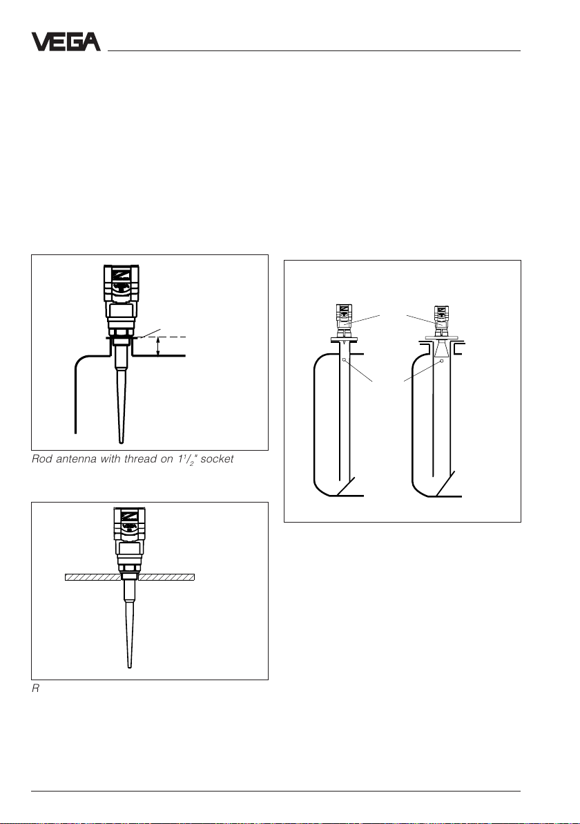
Alternatively to the socket mounting, the rod
antenna can also be mounted on round
vessel openings (holes). Rod antennas are
available for the following openings: 11/2" NPT,
G11/2 A, DN 50, DN 80, DN100 and DN 150.
Note that the PTFE-rod antenna can only
carry limited mechanical load. When
subjected to lateral power, deformation or
even break will be the cause.
Mounting and installation - Measurement of liquids
4.3 Measurement in standpipe
General instructions
Pipe antennas are an option in vessels which
are mechanically complex or where the
product surface is very turbulent.
By focusing of the radar signal within the
measuring pipe, also products with small
dielectric constants (εr= 1,6 to 3) can be
reliably measured.
Reference pane
< 50 mm or 100 mm
or 250 mm
Rod antenna with thread on 11/2" socket
Surge pipe welded
to the tank
Type plate
Vent
Surge pipe in the
socket piece
Pipe antenna systems in the tank
Surge pipes which are open at the bottom
must extend over the full measuring range
(i.e. down to 0% level). Ventilation and surge
holes must be in one axis with the type plate.
Rod antenna with thread on 11/2" threaded
hole
30 VEGAPULS 51 V … 54 V
Page 31

;;;
;;;
;
;
;
;
;
Mounting and installation - Measurement in standpipe
As an alternative to the surge pipe in the
vessel, a pipe antenna outside the vessel is
possible as bypass pipe. Direct the sensor
such that the type plate is in one axis with the
pipe holes or the pipe connection openings.
The polarization of the radar signals enables
considerably more stable measurements with
this directing.
Note that with a measurement in the surge or
bypass pipe the max. measuring range is
reduced by 5 … 20 % (e.g. DN 50: 16 m
instead of 20 m and DN 100 only 19 m
instead of 20 m).
Casting nose
;
;
;
;
;
Pipe flange system as bypass pipe
Adhesive products
When measuring adhesive products, the
inner diameter of the surge pipe must have a
larger nominal width so that build-up does
not cause measuring errors. Surge pipe
diameters of DN 50 to DN 150 can be
connected.
∅
∅
100 %
∅
∅
75 %
Pipe antenna with DN 50, DN 80, DN 100 and
DN 150
0 %
Extended bypass pipe
VEGAPULS 51 V … 54 V 31
Page 32

Mounting and installation - Measurement in standpipe
Standpipe measurement in
inhomogeneous products
If you want to measure inhomogeneous products
or laminated products in surge pipe it must
have long holes or slots. These openings ensure
that the liquid is mixed and balanced at the
correct level.
homogeneous
liquids
slightly inhomogeneous
liquids
The more inhomogeneous the measured
product, the closer the openings should be.
For reasons of radar signal polarization the
holes and slots must be positioned in two
rows displaced by 180°.
The mounting of the radar sensor is then
such that the type plate is in one axis with the
row of holes.
Type plate
Row of holes in one axis with the type plate
inhomogeneous liquids
Openings in a surge pipe for mixing of
inhomogeneous products
32 VEGAPULS 51 V … 54 V
Page 33

Mounting and installation - Measurement in standpipe
Surge pipe with ball valve
When using a ball valve in a surge pipe, it is
possible to carry out maintenance and
service work without opening the vessel (e.g.
with liquid gas or toxic products).
DN 50
Ball valve
ø50
Surge pipe lockable with ball valve
The ball valve diameter must correspond to
the pipe size and provide a flush surface
when in the open position.
Installation error in surge pipe
Missing ventilation hole
Pipe antenna systems must be provided with
a vent at the upper end of a surge pipe. A
missing hole causes wrong measurements.
Correct
The surge pipe open to the bottom must
have a ventilation hole on top
Wrong polarization direction
When measuring in a surge pipe, especially
when there are holes for mixing, it is
important that the radar sensor is directed to
the rows of holes. The two rows of holes of
the surge pipe displaced by 180° must be in
one pane with the polarization direction of the
radar signals. The polarization direction is in
the pane of the type plate.
Wrong
Type plate
The polarization direction is in one pane with
the type plate. The sensor must be directed
with the type plate to the rows of holes or the
openings
VEGAPULS 51 V … 54 V 33
Page 34
;
;
;;;;;;;;;;;;;;;;;;;;;;;;;;;;;;;;
Mounting and installation - Measurement in standpipe
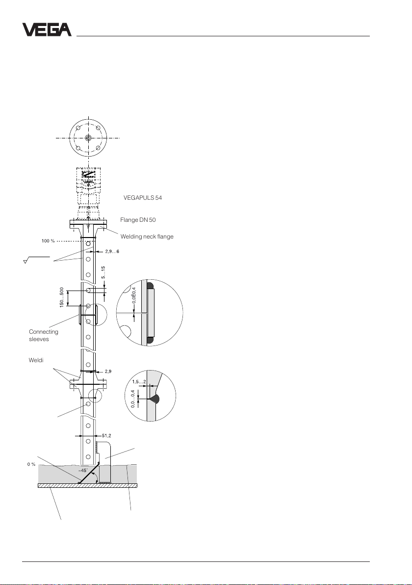
Construction instructions for the surge pipe
Radar sensors for measurement on surge or
bypass pipes are used in flange sizes
DN 50, DN 80, DN 100 and DN 150.
On the left is the construction of a measuring
pipe (surge or bypass pipe) on the example
of a sensor with a DN 50 flange.
Rz ≤ 30
Connecting
sleeves
Welding neck
flanges
Burr the
holes
Deflector
VEGAPULS 54
Flange DN 50
Welding neck flange
Welding of the
connecting sleeve
Welding of the
welding neck flange
Fastening of meas.
pipe
The radar sensor with a DN 50 flange is only
in conjunction with a measuring pipe a
functional system.
The measuring pipe must be smooth inside
(average roughness Rz - 30). Use as
measuring pipe a stainless steel pipe without
joint. Extend the measuring pipe to the
required length with welding neck flanges or
with connecting sleeves. Note that no
shoulders are caused in the pipe during
welding. Fasten the pipe and the flange
before welding in alinement with the inner
sides.
Do not just weld through the pipe wall. The
pipe must be smooth inside. Roughnesses or
joints must be removed carefully as
otherwise strong false echoes and build-up
will be caused.
;;;;;;;;;;;;;;;;;;;;;;;;;;;;;;
Min. product level to be
Vessel bottom
measured (0 %)
34 VEGAPULS 51 V … 54 V
Page 35

Mounting and installation - Measurement in standpipe
;;;;;;;;;;;;;;;;;;;;;;;;;;;;;;;;
On the left you see the contruction of a
measuring pipe on the example of a radar
sensor with a DN 100 flange.
Radar sensors with flanges of DN 80,
DN 100 and DN 150 are equipped with a
VEGAPULS 54
horn antenna. Instead of the welding neck
flange also a smooth welding flange can be
used on the sensor side of these sensors.
Smooth welding flange
In agitated products, fasten the measuring
pipe to the vessel bottom. Provide additional
Flange DN 100
fastenings for longer measuring pipes.
With the deflector on the measuring pipe end,
the radar signals are reflected from the
Burr the
holes
Welding of the smooth
welding neck flange
vessel bottom. This avoids that in nearly
empty vessel and products with low
dielectric constant figures, not the measured
product but the vessel bottom is detected. In
products with low dielectric constant figure
the product is penetrated by radiation and
the vessel bottom delivers at low level
considerably clearer radar echoes than the
product surface.
Connection
sleeves
Welding neck
flanges
Welding of the
welding neck flange
Due to the deflector, the useful signal remains
and hence the measured value can be
clearly detected in nearly empty vessel and
the 0 % level is reliably detected.
Rz ≤ 30
Deflector
VEGAPULS 51 V … 54 V 35
Measuring pipe
fastening
Vessel bottom
Page 36
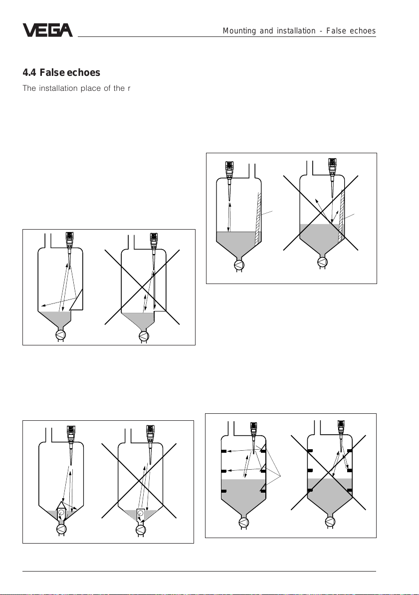
4.4 False echoes
The installation place of the radar sensor
must be selected such that no struts or
inflowing material cross the radar signals.
The following examples show frequent meas.
problems and how they can be avoided.
Shoulders
Vessel forms with flat shoulders pointing to
the antenna can influence the measurement
due to their hard false echoes. Deflectors
above these flat shoulders diffuse the false
echoes and ensure a reliable measurement.
Correct Wrong
Mounting and installation - False echoes
Vessel installations
Struts, such as e.g. a ladder often cause
false echoes. Note when planning a
measurement loop that the radar signals
reach the measured products without
problems.
Correct Wrong
Ladder
Vessel installations
Ladder
Struts
Flat shoulders
Inlets, e.g. for material mixing with flat surface
pointing to the radar sensor, should be
covered by a screen. False echoes are
hence gated out.
Correct Wrong
Shoulders (inlets)
36 VEGAPULS 51 V … 54 V
Struts such as vessel installations can cause
strong false echoes which can overlay the
useful echo. Small shields avoid a direct false
echo reflection. The false echoes are diffused
and filtered out by the meas. electronics as
"echo noise".
Correct Wrong
Shields
Struts
Page 37

Mounting and installation - False echoes
;;
;;
;;
;;
;;
;;
Strong product movements
Heavy turbulences in the vessel, e.g. by
strong stirrers or strong chemical reactions
influence the measurement. A surge or
bypass pipe (figure) of sufficient size allows,
provided that the product causes no buildup in the pipe, always a reliable
measurement even with strong turbulences in
the vessel.
Correct Wrong
Strong product movements
Products which can cause slight build-up
can be measured by using a meas. pipe with
100 mm nominal width and more. In a meas.
pipe of this size, slight build-up is not a
problem.
Build-up
If the radar sensor is mounted too close to
the vessel wall, build-up on the vessel walls
causes false echoes. Position the radar
sensor in a sufficient distance to the vessel
wall. Also note chapter "4.1 General
installation instructions".
Correct Wrong
Build-up
Inflowing material
Do not mount the instruments in or above the
filling stream. Ensure that you detect the
product surface and not the inflowing
material.
Correct
Wrong
Inflowing liquid
VEGAPULS 51 V … 54 V 37
Page 38
4.5 Installation error
Socket piece too long
When mounting the antenna in a too long
socket piece, strong false reflections are
caused, aggravating a measurement. Note
that the horn antenna protrudes at least
10 mm out of the socket piece. When using a
rod antenna, the socket piece must have a
length of max. 100 or 60 mm (with a rod
length of 545 mm the length of the socket
piece must be max. 250 mm).
Correct Wrong
> 10 mm
Horn antenna: Correct and wrong length of
the socket piece
Mounting and installation - Installation error
Parabolic effect on dished boiler head
or basket arch vessel
Round or parabolic tank tops act for the
radar signal like a parabolic mirror. If the
radar sensor is placed to the focus of such a
parabolic tank top the sensor receives
amplified false echoes. The optimum
mounting is generally in the range of the half
vessel radius from the centre.
Correct
< 100 mm
(250 mm)
~ 1/
2
vessel
radius
Wrong
Wrong
Correct
Wrong
< 100 mm
(250 mm)
Mounting on a vessel with parabolic tank top
Rod antenna: Correct and wrong length of
the socket piece
38 VEGAPULS 51 V … 54 V
Page 39

Mounting and installation - Installation error
Surge pipe without ventilation hole
A surge pipe, also called pipe antenna, must
be provided with a breathing hole on the
upper edge of the surge pipe. A missing hole
will cause faulty measurements.
Correct Wrong
Pipe antenna: The surge pipe open to the
bottom must have a ventilation hole on top
Sensor in wrong polarization direction
on the surge pipe
When measuring in a surge pipe, especially if
there are holes in the pipe for mixing, it is
important that the radar sensor is directed to
the row of holes.
The two rows of holes of the surge pipe
displaced by 180° must be in line with the
polarization direction of the radar signals. The
polarization direction is in line with the type
plate.
Correct Wrong
Type plate
VEGAPULS 54 on a surge pipe: The
polarization direction is in line with the type
plate. The sensor must be directed with the
type plate to the rows of holes
VEGAPULS 51 V … 54 V 39
Page 40

Mounting and installation - Installation error
Wrong directing to the product surface
A directing of the sensor which does not
point to the product surface will cause a
weak measuring signal. If possible direct the
sensor axis vertically to the product surface,
to reach optimum measuring results.
Correct Wrong
Ladder
Direct sensor vertically to the product
surface
Ladder
Sensor too close to the vessel wall
If the radar sensor is mounted too close to the
vessel wall, strong interfering signals can be
caused. Build-up, rivets, screws or weld
joints superimpose their echoes to the useful
signal or useful echo. Hence note a sufficient
distance of the sensor to the vessel wall.
In case of good reflection conditions (liquids
without vessel installations) we recommend to
select the sensor distance so that there is no
vessel wall within the inner emission cone. For
liquids with worse reflection conditions it is
useful that there are also no interfering
installations within the outer emission cone.
Note chapter "4.1 General installation
instructions".
Foam generation
Strong, dense and creamy foam on the
product can cause faulty measurements.
Provide measures to avoid foam or measure
in a bypass pipe. Check if necessary the use
of another measuring principle, e.g.
capacitive electrodes or hydrostatic pressure
transmitters.
40 VEGAPULS 51 V … 54 V
Page 41

Electrical connection
5 Electrical connection
5.1 Connection and connection
cable
Safety information
Ensure that the instrument is unpressurized
before you start work. Always switch off the
power supply before you carry out clamping
work on the radar sensors. Protect yourself
and the instruments. Especially when you
use sensors which do not work with low
voltage.
Skilled staff
Instruments operated in Ex-areas must only
be connected by skilled staff. This staff must
note the installation regulations and the
attached type approvals and conformity
certificates.
Connection
A standard two-wire cable with max. 2,5 mm
can be used for connection. Very often
"Electromagnetic pollution" by electronic
actuators, energy lines and transmitting
stations is so considerable that the two-wire
line must be screened.
We recommend to use a screening. This
screening prevents against future
interferences. It is useful to earth the cable
screens on both ends, however it must be
noted that no earth compensation currents
flow via the sensor cable screens. You avoid
earth compensation currents by connecting
the cable screen on one earth side (e.g. in
the switching cabinet) via a capacitor (e.g.
1 µF; 100 V) with earth potential in case of
earthing on two ends. Use a very low
impedance earth connection (foundation,
plate or mains earth).
Ex-protection
If an instrument is used in hazardous areas
the appropriate regulations, conformity
certificates and type approvals for sensors
and separators or safety barriers must be
noted (e.g. DIN VDE 0165).
Sensors used in Ex-area must only be
operated on intrinsically safe circuits. The
permissible electrical values are stated in the
conformity certificate or the type approval.
Connection cable
Note that the connection cables must be specified
for the expected operating temperatures in your
systems. The cable must have an outer diameter
of 5 … 9 mm. Otherwise the seal effect of the
cable entry will not be ensured.
2
Cables for intrinsically safe circuits must be
marked blue and must not be used for other
circuits.
Earth conductor terminal
On VEGAPULS 51/52 sensors with a 11/2"
thread of plastic, the earth conductor terminal
is galvanically isolated.
On all VEGAPULS 53/54 sensors as well as
VEGAPULS 51/52 sensors with metal thread,
the earth conductor terminal is galvanically
connected with the metal process
connection.
VEGAPULS 51 V … 54 V 41
Page 42
5.2 Connection of the sensor
After having mounted the sensor in the
measuring position acc. to the instructions in
chapter "4 Mounting and installation", loosen
the closing screw on the top of the sensor.
The sensor cover with the optional indicating
display can then be opened. Unscrew the
compression screw and shift the screw over
the approx. 10 cm dismantled connection
cable. The compression screw is protected
with a safety lock-in position against
automatic loosening.
Voltage supply
and digital measuring signal
Electrical connection - Connection of the sensor
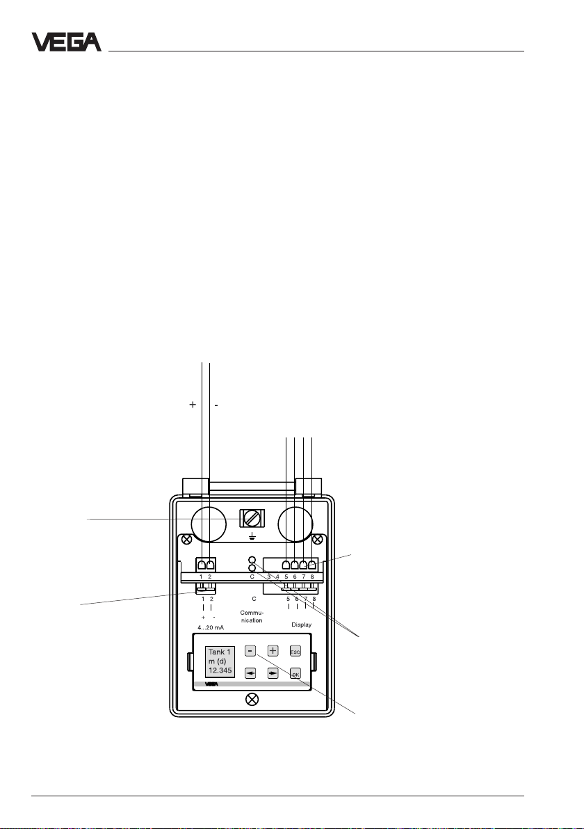
Now loop the cable through the cable entry
into the sensor. Screw the compression
screw again to the cable entry and clamp the
dismantled wires of the cable to the
appropriate terminal positions.
The terminals operate without terminal screw.
Press the white opening buckets with a small
screwdriver and insert the copper core of the
connection line into the terminal opening.
Check the position of the lines in the terminal
position by slightly pulling on the connection
lines.
To the indicating instrument in the
sensor cover or to the external
indicating instrument VEGADIS 50
Earth terminal
The earth terminal must be
connected to system earth
Spring terminals
Tw o-wire technology
42 VEGAPULS 51 V … 54 V
Spring terminals to
VEGADIS
(max. 2,5 mm
cross-section area
of conductor)
Sockets for connection of the
interface adapter
VEGACONNECT
Pluggable
adjustment module
MINICOM
2
Page 43

Electrical connection - Connection of the external indicating instrument
5.3 Connection of the external indicating instrument VEGADIS 50
Loosen the four screws of the housing cover
on VEGADIS 50.
You can facilitate the connection procedure
by fastening the housing cover during
connection with two screws on the right of the
housing (figure).
Terminal board VEGADIS 50
3
2
1
4
5
to DISPLAY in the cover of
VEGADIS 50
8
6
7
Adjustment module
-
Tank 1
m (d)
12.345
3215678
-
+
OUTPUT
+
DISPLAY
VEGADIS 50
ESC
OK
16.85
Voltage supply
and
digital measuring signal
+
-
12 C 567843
Screws
Sensor terminal box
-
+
+
ESC
-
Tank 1
m (d)
12.345
OK
VEGAPULS 51 V … 54 V 43
(open)
Page 44

6 Set-up
6.1 Adjustment structure
Series 50 radar sensors can be adjusted
with
- PC (adjustment program VVO)
- detachable adjustment module MINICOM
- signal conditioning instrument VEGAMET.
The adjustment must be only carried out with
one adjustment medium.
Adjustment program VVO
With the adjustment program VVO
sual Operating System) on the PC you can
adjust the radar sensors very comfortably.
The PC communicates via the interface
adapter VEGACONNECT 2 or the standard
RS232 interface cable digitally with the
sensor. The adjustment can be hence carried
out directly on the sensor, in any individual
position of the signal line or on the
processing system VEGAMET/VEGALOG.
Note:
The adjustment with PC via the interface
adapter VEGACONNECT 2 directly on the
sensor or on the signal line enables only the
"parameter adjustment" and corresponds to
the adjustment with PC on VEGAMET or
VEGALOG on the following pages.
Adjustments to "
not possible when the VEGACONNECT 2 is
connected directly to the sensor or the signal
line and hence not described separately in
this operating instruction.
Configuration
(VEGA Vi-
" however are
Set-up - Adjustment structure
Signal conditioning instrument VEGAMET
The signal conditioning instrument VEGAMET
enables with the 6-key adjustment field with
text display the parameter adjustment in the
same functional volume than the adjustment
program VVO on the PC.
Adjustment module MINICOM
With the adjustment module MINICOM you
can adjust in the sensor or in the external
indicating instrument VEGADIS 50. The
adjustment module enables with the 6-key
adjustment field with text display the
parameter adjustment in the same functional
volume than the adjustment program VVO or
the 6-key adjustment field with text display on
the signal conditioning instrument VEGAMET.
The configuration adjustments however are
only possible with the adjustment program
VVO or the 6-key adjustment field with text
display on the signal conditioning instrument
VEGAMET.
The adjustment is always the same, whether
you set-up a measuring sytem (unit
consisting of sensor and signal conditioning
instrument VEGAMET or sensor and
processing system VEGALOG) with the
adjustment software VVO, with the signal
conditioning instrument or with the adjustment
module MINICOM:
- first of all configure in the menu
a meas. system and
- carry out the parameter adjustment of the
sensors in the menu "
"Configuration"Configuration
"Configuration
"Configuration"Configuration
Instrument dataInstrument data
Instrument data
Instrument dataInstrument data
".
"
44 VEGAPULS 51 V … 54 V
Page 45

Set-up - Adjustment structure
Configuration Configuration
Configuration means to coordinate or
Configuration Configuration
determine once. In the menu Configuration
the signal conditioning instrument is informed
about the general configuration:
- which kind of sensor is connected (radar,
ultrasonic, process pressure…),
- what kind of parameter or application is
concerned (level, gauge, distance…)
- to which input the sensor is connected
- which outputs (current, voltage, relay, fault
signals, indication…) should be
coordinated to which input in which way
(inverted, threshold value controlled…).
After these adjustments (configuration) had
been carried out, the meas. system goes to
operating condition and the signal
conditioning instrument will display a
measured value. Now the sensor parameter
adjustment (adjustment, unit, linearisation
curve, sensor adaption…) can be carried
out.
Parameter adjustment Parameter adjustment
Parameter adjustment means to enter values.
Parameter adjustment Parameter adjustment
Parameters are entered in the signal
conditioning instrument as well as in the
connected sensors. For example:
- Min. and max. adjustment
- Meas. range limits
- Physical unit, decimal point
- Linearisation curves
- Integration time
- Meas. environment (solid, liquid,
foam generation, operating range…)
- False echo memory
- Inversion of the measured value etc.
Now all required adjustments for a precisely
adapted sensor are carried out for a reliable
measurement.
6.2 Adjustment with PC on VEGAMET
The PCThe PC
The PC with the adjustment program VVO
The PCThe PC
VV
VV
(
VEGA
VV
- to the sensor
- to the signal line
to the signal conditioning instrumentto the signal conditioning instrument
-
to the signal conditioning instrument
to the signal conditioning instrumentto the signal conditioning instrument
VEGAMET VEGAMET
VEGAMET 514V/515V
VEGAMET VEGAMET
- to the processing system VEGALOG 571
For connection of a PC to a signal
conditioning instrument you require the
interface adapter VEGACONNECT 2. The PC
communicates via the interface adapter
VEGACONNECT 2 with the signal
conditioning instrument and the sensor.
Hence a digital adjustment signal is
superimposed to the signal and supply line
between sensor and signal conditioning
instrument. In chapter "2.2 Configuration of
measuring systems" the connection of the PC
in different coordinations is shown.
In any case you are requested to enter or
enquire something, this is marked in the
following with a dot, such as e.g.:
• Choose …
• Start …
• Click to …
Now start to
• Connect the standard plug of
VEGACONNECT 2 (9-pole) with the
interface COM 1 or COM 2 of your PC.
• Plug the two small pin plugs of
VEGACONNECT 2 into the CONNECTsocket of the signal conditioning
instrument.
• Now switch on the voltage supply of the
signal conditioning instrument.
OO
Visual
Operating) can be connected:
VV
OO
After approx. 1…2 minutes (selfcheck) the
meas. system is generally ready for
operation and indicates measured values or
a failure.
VEGAPULS 51 V … 54 V 45
Page 46
Set-up - Adjustment with the PC on VEGAMET
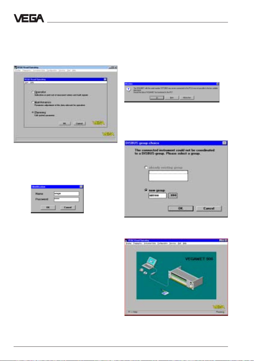
• Now start the adjustment software VVO on
your PC.
• In the entrance screen you choose with the
arrow keys or the mouse the item
PlanningPlanning
"
Planning
PlanningPlanning
In the next window you are asked for the
identification.
• Enter under the name "
• Also enter under the password
The adjustment program, in the following
called VVO, gets in contact with the
connected coordination/sensor …… and
displays after a few seconds whether and
with which coordination/sensor a connection
exists.
" and click to "
OKOK
OK
".
OKOK
VEGAVEGA
VEGA
VEGAVEGA
".
VEGAVEGA
"
VEGA
VEGAVEGA
".
If VVO (adjustment software) gets in contact
with the signal conditioning instrument for the
first time, you are asked if the data should be
transmitted from the signal conditioning
instrument to the PC.
YY
• Click to "
In the following menu window "
choice
or keep the suggested file name.
• Click to "
window.
eses
Y
es
"
YY
eses
DISBUS-group
" you can give a name to the database
OKOK
OK
", and you are in the main menu
OKOK
Note:
If you do not get a sensor connection, please
check:
- is the sensor fed with power supply (min.
20 V)?
- do you use VEGACONNECT instead of the
new VEGACONNECT 2 ?
46 VEGAPULS 51 V … 54 V
Page 47
Set-up - Adjustment with the PC on VEGAMET
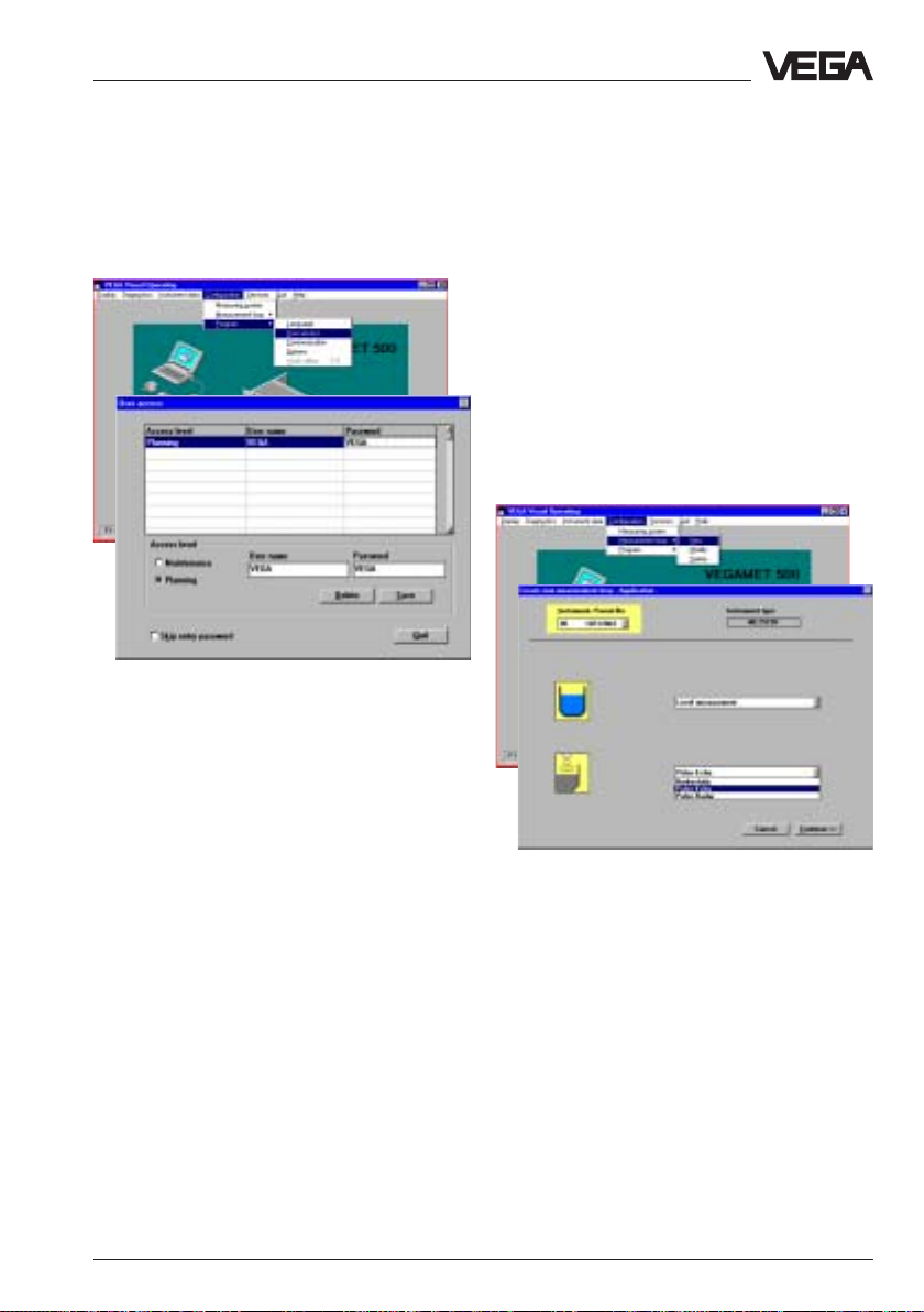
User access
The preadjusted identification can be
modified later in the menu "
Before starting the configuration:Before starting the configuration:
Before starting the configuration:
Before starting the configuration:Before starting the configuration:
The signal conditioning instruments are
preconfigured depenpent on the sensor type
you have ordered with the signal conditioning
instrument.
User accessUser access
User access
User accessUser access
".
Configuration
Before starting the set-up:Before starting the set-up:
Before starting the set-up:
Before starting the set-up:Before starting the set-up:
Take some time to carry out the set-up stepby-step with the PC and soon you will no
more require the following pages.
Create new measurement loop
• Choose the menu "
Measurement loop/Create newMeasurement loop/Create new
Measurement loop/Create new" and you
Measurement loop/Create newMeasurement loop/Create new
are in the menu window
measurement loop - Application"
Configuration/Configuration/
Configuration/
Configuration/Configuration/
"Create new
Generally you will use a preconfiguredGenerally you will use a preconfigured
Generally you will use a preconfigured
Generally you will use a preconfiguredGenerally you will use a preconfigured
signal conditioning instrument.signal conditioning instrument.
signal conditioning instrument.
signal conditioning instrument.signal conditioning instrument.
Hence you normally do not have to make anyHence you normally do not have to make any
Hence you normally do not have to make any
Hence you normally do not have to make anyHence you normally do not have to make any
adjustments in the menu "Configuration"adjustments in the menu "Configuration"
adjustments in the menu "Configuration"
adjustments in the menu "Configuration"adjustments in the menu "Configuration"
beginning on this page and in this case youbeginning on this page and in this case you
beginning on this page and in this case you
beginning on this page and in this case youbeginning on this page and in this case you
can directly choose the menu "Parametercan directly choose the menu "Parameter
can directly choose the menu "Parameter
can directly choose the menu "Parametercan directly choose the menu "Parameter
adjustment" (on page 50).adjustment" (on page 50).
adjustment" (on page 50).
adjustment" (on page 50).adjustment" (on page 50).
If as an exception your signal conditioning
instruments are not preconfigured, then start
with the following chapter "
this page and continue with the adjustments
in the chapter "Parameter adjustment" on
page 50.
VEGAPULS 51 V … 54 V 47
Configuration
" on
• Choose the parameter
measurement"measurement"
measurement" (gauge or distance) and the
measurement"measurement"
sensor type (
• Click to "
"pulse radar""pulse radar"
"pulse radar"
"pulse radar""pulse radar"
ContinueContinue
Continue
ContinueContinue
"
"Level "Level
"Level
"Level "Level
for radar).
Page 48

Set-up - Adjustment with the PC on VEGAMET
• Choose "
"
no options
• Click to "
"New application - select meas. loop"
opens
• Choose one of the two inputs of the signal
conditioning instrument VEGAMET
(VEGAMET 514 V has just one sensor
input) and click to "
After a few seconds the menu window
"Create new measurement loop - Sensor
configuration" opens.
• Click in the menu window "Create new
measurement loop - Sensor configuration"
to "
The menu window "
opens.
Standard level measurementStandard level measurement
Standard level measurement" and
Standard level measurementStandard level measurement
no optionsno options
no optionsno options
Sensor coordinationSensor coordination
Sensor coordination
Sensor coordinationSensor coordination
"
ContinueContinue
Continue
ContinueContinue
Sensor coordination
", and the menu window
OKOK
OK
"
OKOK
".
"
• Click to "
• Then click to "
number of the sensor which you want to
coordinate e.g. to input 1.
• Confirm with "
• Click in the menu window "Sensor
coordination" again to "
You are again in the menu window
Sensor searchSensor search
Sensor search
Sensor searchSensor search
InputInput
Input
" and choose the serial
InputInput
OKOK
OK
".
OKOK
".
OKOK
OK
OKOK
".
"Create
new measurement loop - Sensor
configuration"
• Click to "
48 VEGAPULS 51 V … 54 V
ContinueContinue
Continue
ContinueContinue
"…
Page 49
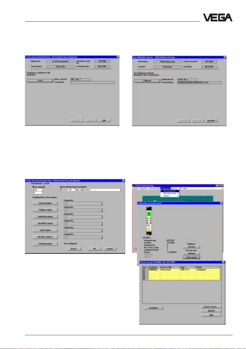
Set-up - Adjustment with the PC on VEGAMET
• Click in the menu window "
Create new
measurement loop - Measurement loop
designation
• Enter in the menu window "
" to "
LevelLevel
Level
LevelLevel
".
Create new
measurement loop - Measurement loop
designation
and a description.
In this menu window you can choose with
which output signals your level should be
provided, e.g. as current, voltage, relay
signal etc.
• Confirm your adjustments with "
" a measurement loop number
OKOK
OK
".
OKOK
• Click to "
adjustments are transmitted.
Configuration information
In the menu "
system
configuration.
QuitQuit
Quit
" and wait a moment until the
QuitQuit
Configuration/Measuring
" you can check your actual
VEGAPULS 51 V … 54 V 49
Page 50

Parameter adjustment
In the menu "
adjustment
sensor adjustments.
Adjustment
• Choose the menu
Instrument data/Parameter adjustmentInstrument data/Parameter adjustment
"
Instrument data/Parameter adjustment
Instrument data/Parameter adjustmentInstrument data/Parameter adjustment
and then the sensor for which you want to
carry out the parameter adjustment.
When you have configured just one sensor
on the signal conditioning instrument, just one
sensor will be offered as choice.
Instrument data/Parameter
" you carry out all important
",
Set-up - Adjustment with the PC on VEGAMET
• First choose "
• Click in the menu window "Adjustment" to
Min / Max - AdjustmentMin / Max - Adjustment
"
Min / Max - Adjustment
Min / Max - AdjustmentMin / Max - Adjustment
AdjustmentAdjustment
Adjustment
AdjustmentAdjustment
"
"
The menu window "
opens.
You can carry out the min./max. adjustment
"with medium" (adjustment with vessel filling)
or
"without medium"
filling, also with empty vessel).
Generally the adjustment is carried out
without medium whereby during adjustment
you are completely independent from the
actual vessel filling.
If you want to carry out the adjustment with
medium, you have to carry out the min.
In the heading of the menu window which is
going to open, you now see the previously
entered measurement loop name and the
designation.
50 VEGAPULS 51 V … 54 V
adjustment with emptied (also partly
emptied) vessel and the max. adjustment
with filled (also partly filled) vessel.
It is hence comfortable and quick to carry out
the adjustment without medium as shown in
the example.
Min/Max - adjustment
(unaffected by the vessel
"
Page 51
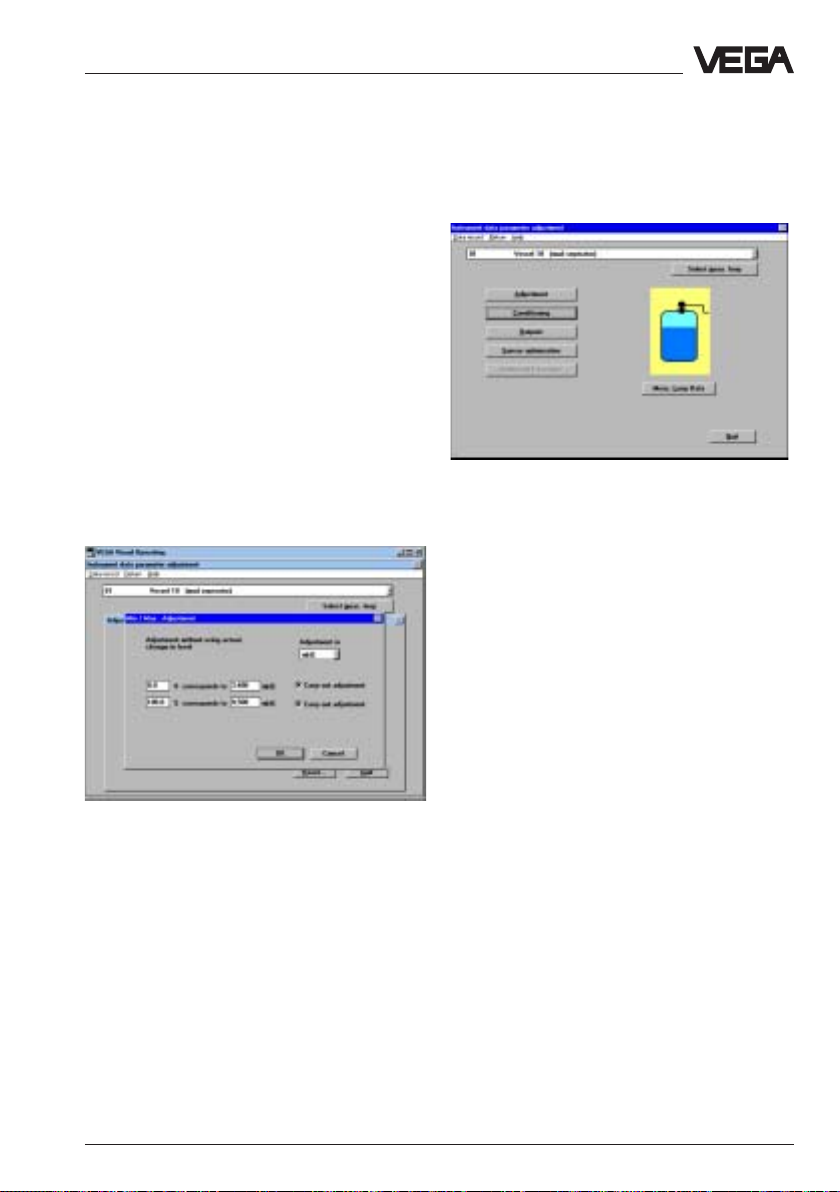
Set-up - Adjustment with the PC on VEGAMET
• Choose "
• Choose in the following window if you want
to make the adjustment in meters (m) or in
feet
• Enter a
level and the appropriate
%.
In the example the 0 % filling is at a product
distance of 3,400 m and the 100 % filling at a
product distance of 0,500 m.
Note:Note:
Note:
Note:Note:
The sensor can only detect levels within the
defined operating range. For level detection
outside the operating range, the operating
range must be corrected appropriately in the
menu "Sensor optimisation/Meas.
environment" on page 55/56.
no (adjustment without medium)no (adjustment without medium)
no (adjustment without medium)
no (adjustment without medium)no (adjustment without medium)
(ft).
distance distance
distance for the upper and lower
distance distance
filling degree filling degree
filling degree in
filling degree filling degree
"
You are again in the menu window "
ment data parameter adjustment
Hence the sensor electronics has two
characteristics points (MIN and MAX), out of
which a linear proportionality between
product distance and the percentage filling of
a vessel is generated.
However the characteristics points must not
be at 0 % and 100 % but the difference
should be as large as possible (e.g. at 20 %
and at 80 %). The min. product distance of
the characteristics point for min./max.
adjustment should be 50 mm. When the
characteristics points are too close together,
the possible meas. error increases.
It is hence suitable to carry out the
adjustment at 0 % and at 100 %.
".
Instru-
• Confirm your adjustments with "
you are again in the menu window
"
Adjustment
• Click in the menu window "Adjustment" to
QuitQuit
"
Quit
QuitQuit
VEGAPULS 51 V … 54 V 51
".
".
OKOK
OK
OKOK
", and
In the menu
adjustment/Conditioning/Linearisation"
can adjust later another linear dependence
between product distance and the
percentage filling degree (see later subpoint
linearisation).
"Instrument data/Parameter
you
Page 52

Conditioning
Set-up - Adjustment with the PC on VEGAMET
• Click in the menu window "Instrument data
parameter adjustment" to "
The menu window "
• Click to "
In the menu "
0 % and 100 %-values of the parameter and
their unit. Hence you inform the sensor, e.g.
that at 0 % filling there are 45,5 litres and at
100 % filling 1200 litres in the vessel.
The sensor indication then displays with empty
vessel 45,5 litres (0 %) and at full vessel
1200 litres (100 %).
ScalingScaling
Scaling
ScalingScaling
Conditioning
".
Scaling
" you enter the actual
ConditioningConditioning
Conditioning
ConditioningConditioning
" opens.
".
As parameter you can choose
(figures),
and coordinate an appropriate meas. unit
(e.g. l, hl).
The sensor indication displays then the figure
in the chosen parameter and unit.
• Save the adjustments in the menu "
volume, mass, height
OKOK
with "
OK
".
OKOK
"dimensionless
and
distance"
Scaling
"
A warning is displayed that the indication has
been formerly adjusted to %. Confirm the
adjustment, for indication in litres.
The adjustments are now transmitted to the
sensor and you are again in the menu
window "
52 VEGAPULS 51 V … 54 V
Conditioning
".
Page 53

Set-up - Adjustment with the PC on VEGAMET
Linearisation
The relation of level and volume is described
with so called linearisation curves.
If in your vessel there is another than a linear
dependence between level ("percentage
value" of the level) and the volume
("linearised" value of the volume), choose the
menu
"Instrument data/Parameter
adjustment/Conditioning"
• Click in the menu window "
the menu point "
LinearisationLinearisation
Linearisation
LinearisationLinearisation
Conditioning
".
" to
In the menu window "
that "
Linear
the dependence between the percentage
value of the filling volume and the value of the
level is linear.
Beside the two given linearisation curves
"
Cylindrical tank
can also adjust six "
curves
• To enter an own vessel geometry or a user
programmable filling curve, click to "
programmable curveprogrammable curve
programmable curve
programmable curveprogrammable curve
• Click to "
First of all a linear relation (a straight line) is
displayed.
In the field "
level in percent of the adjusted meas. range
(meas. window) is displayed. You have
adjusted the meas. range during the min./max.
adjustment to 0,500 … 3,400 m.
" is preadjusted. This means that
".
EditEdit
Edit
EditEdit
Transfer measured value
Linearisation
" and "
Spherical tank
user programmable
".
".
" you see
" you
UserUser
User
UserUser
" the actual
VEGAPULS 51 V … 54 V 53
Page 54
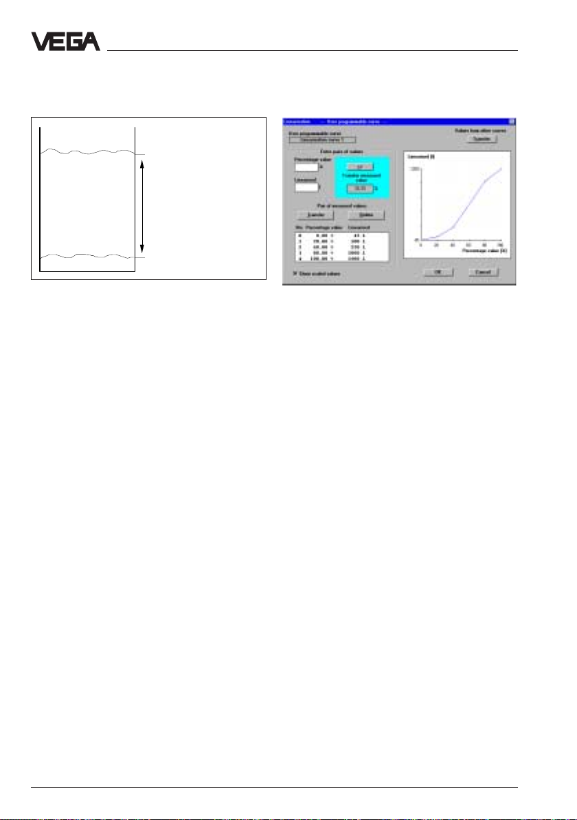
Set-up - Adjustment with the PC on VEGAMET
Max.
Min.
100 % (0,500 m) corresponds
to
1200 litres
Meas. range
0 % (3,400 m) corresponds to
45,5 litres
The user programmable linearisation curve is
generated out of linearisation points, the so
called value pairs. A value pair consists of
"
Linearised
and "
(percentage value of the filling)
Percentage value
" (percentage value of
the level relating to the meas. range).
If the linearisation points or value pairs of
your vessel are not known to you, you must
gauge the vessel by litres.
Gauging by litres
In the characteristics of the following figure
you see five linearisation points (0, 1, 2, 3,
and 4) or value pairs. Between the
linearisation points there is always a linear
interpolation.
Click to "
Indication in scaled values
", to have
the adjusted meas. unit indicated on the yaxis (left bottom part of the menu window).
Linearisation point 1 is at a filling level of 20 %
(20 % of the meas. distance of
0,500 m … 3,400 m).
In our example there are 100 litres at 20 %
filling in the vessel.
Linearisation point 2 is at a filling level of
40 %. At this filling level there are 250 litres in
the vessel.
Linearisation point 3 is at a filling level of
80 %, where 1000 litres are in the vessel.
Linearisation point 4 is at a filling level of
100 % (level distance 0,500 m), where 1200
litres are in the vessel.
You can enter max. 32 linearisation points
(value pairs) per linearisation curve.
• Quit the menu with "
• Confirm the message with "
OKOK
OK
OKOK
".
OKOK
OK
", and your
OKOK
individual linearisation curve will be saved
in the sensor.
Back to the menu window "
Conditioning
" you
can enter a measured value integration with
the menu point "
Integration time
". This is
useful for fluctuating product surfaces to
avoid that the measured value indication and
output changes permanently. As a standard
feature an integration time of 0 seconds is
adjusted.
• Quit the menu with "
OKOK
OK
OKOK
".
You are now again in the menu window
"Conditioning"
54 VEGAPULS 51 V … 54 V
.
Page 55

Set-up - Adjustment with the PC on VEGAMET
• Quit the menu window with "
You are again in the menu window "
QuitQuit
Quit
QuitQuit
".
Instru-
ment data parameter adjustment".
• Click to "
Outputs
• Choose in the main menu window "
ment data parameter adjustmentment data parameter adjustment
ment data parameter adjustment
ment data parameter adjustmentment data parameter adjustment
the following window the required sensor.
• Choose in the menu window "
data parameter adjustment
QuitQuit
Quit
QuitQuit
".
" and in
Instrument
OutputsOutputs
" "
Outputs
OutputsOutputs
Instru-Instru-
Instru-
Instru-Instru-
".
You are in the menu window "
• Click to "
signal mode of the 0/4…20 mA output
signal.
• If you have made adjustments in this menu
window, click to "
• Click to "
You are now again in the menu window
"Outputs"
• Click in the menu window "
menu point "
choose "
Current outputCurrent output
Current output
Current outputCurrent output
SaveSave
Save
QuitQuit
Quit
QuitQuit
.
Sensor displaySensor display
Sensor display
Sensor displaySensor display
SaveSave
".
Display of measured valueDisplay of measured value
Display of measured value
Display of measured valueDisplay of measured value
Outputs
", to adjust the
".
Outputs
".
".
" to the
", and
VEGAPULS 51 V … 54 V 55
Page 56

• Choose under
"Parameter" "
• Choose under "
e.g. litres.
• Enter the meas. distance in meter which
you have entered for the min./max.adjustment and the appropriate litre values
corresponding to the min.-value and the
max.-value. In the example 45 litres and
1200 litres.
• Click to
• Click in the window "
QuitQuit
"
Quit
"
QuitQuit
• Click in the window "
value
" to "
"Sensor No." "
ScaledScaled
Scaled"
ScaledScaled
Scaling for sensor display
SaveSave
"
Save
"
SaveSave
QuitQuit
Quit
"
QuitQuit
AA
A"
and under
AA
.
Sensor-Display
" to
Display of measured
Set-up - Adjustment with the PC on VEGAMET
Sensor optimisation
In the menu "
carry out special optimizing adjustments of
the sensors and can optimize e.g. by means
of the echo curve the installation position of
the sensor.
Meas. environment
• Choose in the main menu window the menu
Instrument data/Parameter adjustmentInstrument data/Parameter adjustment
"
Instrument data/Parameter adjustment
Instrument data/Parameter adjustmentInstrument data/Parameter adjustment
• Choose in the menu window
data parameter adjustment"
Sensor optimisationSensor optimisation
"
Sensor optimisation
Sensor optimisationSensor optimisation
Sensor ASensor A
"
Sensor A
Sensor ASensor A
"
Sensor optimisation
", and click to
"
" you can
"Instrument
the menu point
"
You are again in the menu window "
• Click to
You are again in the menu window "
QuitQuit
"
Quit
QuitQuit
"
ment data parameter adjustment
56 VEGAPULS 51 V … 54 V
".
Outputs
Instru-
"
Page 57

Set-up - Adjustment with the PC on VEGAMET
• First click to "
The window "
With the menu point "
can define the measuring range of the sensor
deviating from the "
As a standard feature the measuring range
normally corresponds to the min./max.
adjustment.
Generally it will be suitable to choose the
measuring range approx. 5 % larger than the
range determined by the min./max.
adjustment.
In the example: Min. adjustment to 0,500 m,
Meas. environmentMeas. environment
Meas. environment
Meas. environmentMeas. environment
Meas. environment
".
" opens
Measuring range
Min/Max-Adjustment
max. adjustment to 3,400 m.
" you
".
• In the menu window "
you click to the options corresponding to
your application.
• Confirm with "OK".
After some seconds of saving during which
the adjustments are saved in the sensor, you
are again in the window "
• Click in the menu window "
environment
You are again in the menu window "
optimisation
Echo curve
With the menu point "
look at the course and the strength of the
detected radar echo.
" to "
".
Measuring conditions
Meas. environment
Meas.
QuitQuit
Quit
".
QuitQuit
Echo curve
" you can
Sensor
"
".
If due to vessel installations, strong false
echoes have to be expected, a correction of
the installation position (if possible) can help
to localize and reduce the size of the false
• Save the adjustments with "
• Click in the menu window "
environment
VEGAPULS 51 V … 54 V 57
Measuring conditionMeasuring condition
" to "
Measuring condition
Measuring conditionMeasuring condition
OKOK
OK
OKOK
Meas.
"
".
echo by monitoring the echo curve.
Page 58

Set-up - Adjustment with the PC on VEGAMET
In the following figure you see the echo curve
before correction of the installation angle
(directing to the product surface) with a false
echo which has nearly the same size than the
product echo and which is caused by a strut.
In the next figure you see the echo curve
after optimum directing of the sensor to the
product surface (sensor axis vertically to the
product surface).
false echoes at a poorer degree than the
useful echo.
• Click in the menu window "
optimisation
storagestorage
storage
storagestorage
• Click in the menu window "
storage
window "
" to the menu point "
".
Learn false echoesLearn false echoes
" to "
Learn false echoes
Learn false echoesLearn false echoes
Learn false echoes
Sensor
False echoFalse echo
False echo
False echoFalse echo
False echo
". The small
" opens.
• Enter here the checked product distance
and click to "
You see that the false echo caused by the
strut is here reduced by approx. 20 dB
against the useful echo and hence can no
more influence the measurement.
• Quit the menu window
"
Quit
".
With the menu point "
the menu window "
can cause the sensor to mark false echoes.
The sensor electronics then saves the false
echoes in an internal database and treats the
58 VEGAPULS 51 V … 54 V
"Echo curve"
False echo storage
Sensor optimisation
with
" in
" you
Create newCreate new
Create new
Create newCreate new
".
Page 59

Set-up - Adjustment with the PC on VEGAMET
Hence you cause the sensor to mark all
echoes in front of the product echo as false
echoes. This avoids that the sensor detects
erroneously a false echo as level echo.
• Click to "
The echo curve and the false echo marking is
displayed.
• Quit the menu with "
You are again in the menu window "
optimisation
With the menu point "
options of the menu "
basic adjustment.
• Quit the menu window "Sensor
optimisation" with "
"
Sensor choice for sensor optimisation
You are then in the menu window "
data parameter adjustment
Show echo curveShow echo curve
Show echo curve
Show echo curveShow echo curve
QuitQuit
Quit
".
QuitQuit
".
Reset
" you reset all
Sensor optimisation
QuitQuit
Quit
" the menu window
QuitQuit
"
Sensor
" to
"
Instrument
".
• Click to "
"
you measuring system in the information
windows.
ApplicationApplication
Application
ApplicationApplication
VEGAMETVEGAMET
VEGAMET
VEGAMETVEGAMET
", to get detailled information on
Input No. AInput No. A
", to "
Input No. A
Input No. AInput No. A
" and
• Click in the window
parameter adjustment"
DataData
Data".
DataData
VEGAPULS 51 V … 54 V 59
"Instrument data
Meas. LoopMeas. Loop
to "
Meas. Loop
Meas. LoopMeas. Loop
Page 60
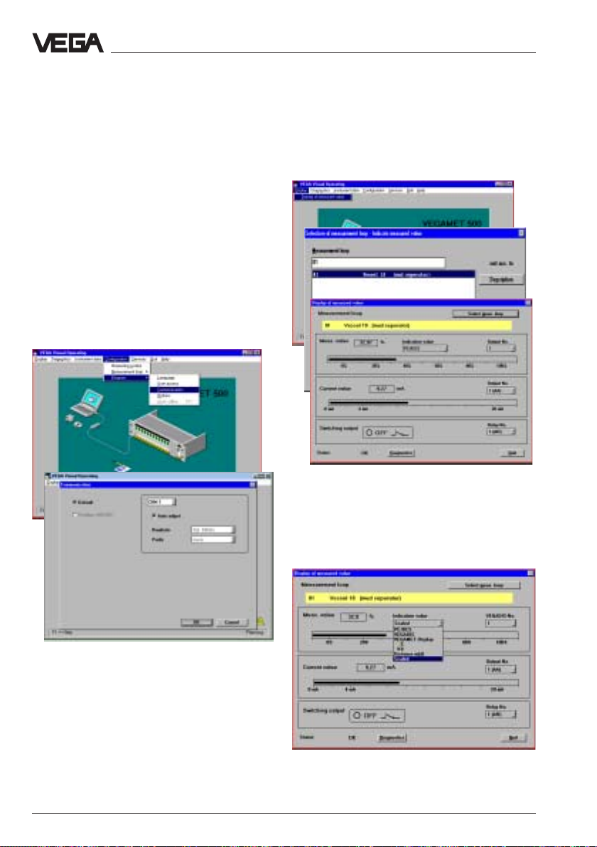
• Close the information windows.
• Quit the menu "
• Click in the menu window
parameter adjustment"
You are now again in the main menu window.
Change COM-interface
In the menu "
Communication
parameters of your PC or change the used
COM-Port.
Meas. Loop Data
".
"Instrument data
QuitQuit
to "
Quit
".
QuitQuit
Configuration/Program/
" you can adjust the interface
Set-up - Adjustment with the PC on VEGAMET
Display of measured value
• Click in the main menu window to the menu
DisplayDisplay
//
"
Display
DisplayDisplay
choose the measurement loop (in the
example only one is available).
Display of measured valueDisplay of measured value
/
Display of measured value
//
Display of measured valueDisplay of measured value
", and
• Choose in the line
ScaledScaled
"
Scaled
" and the measured value is
ScaledScaled
displayed e.g. in litres and volume percent
as well as the actual signal current in the
0/4 ... 20 mA signal line.
60 VEGAPULS 51 V … 54 V
"Indication value"
Page 61
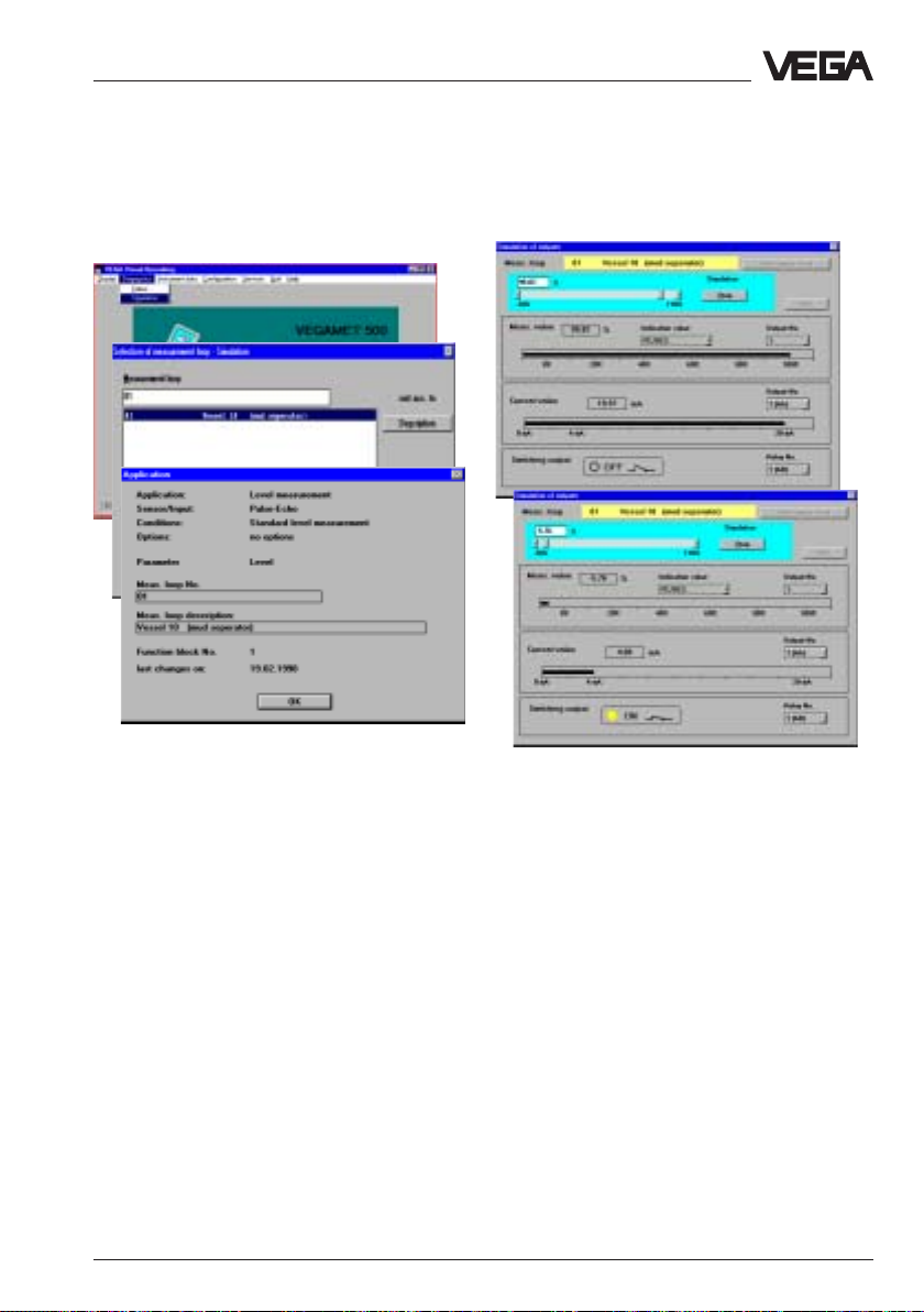
Set-up - Adjustment with the PC on VEGAMET
Simulation
• Click to the menu "
and choose the measurement loop
(in the example only one is available).
Diagnostics/SimulationDiagnostics/Simulation
Diagnostics/Simulation
Diagnostics/SimulationDiagnostics/Simulation
"
• Click in the turquoise window cutout to
StartStart
"
Start
".
StartStart
The menu window "
which is simular to the previous menu window
opens. In this menu window however you can
simulate the filling of the vessel or the signal
current and the indication to an individual
value (measured value simulation).
First of all the actual measured value and the
signal current are displayed.
VEGAPULS 51 V … 54 V 61
Simulation of outputs
",
The grey scrollbar in the turquoise window
cutout becomes active. With this scollbar you
can modify the measured value in the range
of -10 % … 110 % and hence simulate the
filling or emptying of your vessel.
In the field with the figures above the scrollbar you can enter an individual %-value for
the filling degree.
Page 62

Backup
• Click to
Services/Backup/SensorsServices/Backup/Sensors
"
Services/Backup/Sensors
Services/Backup/SensorsServices/Backup/Sensors
Set-up - Adjustment with the PC on VEGAMET
"
Saved sensor data can be transferred later
to other sensors. If you have e.g. a system
with several of the same storage vessels and
identical sensors, it is sufficient to configure
one sensor and then transfer to the other
sensors.
""
• Choose the menu
configuration/Sensorsconfiguration/Sensors
configuration/Sensors
configuration/Sensorsconfiguration/Sensors
Services/RestoreServices/Restore
"
Services/Restore
""
Services/RestoreServices/Restore
""
"
""
In the menu window "
the serial number is displayed. You can save
the sensor individually or in groups with all
adjustments in a directory of your choice on
your PC. In addition you can add a short note
to each backup.
You also save the adjustments of the signal
conditioning instrument VEGAMET:
Backup
" the sensor with
In this menu window you choose in the yellow
window cutout a sensor (or a signal
conditioning instrument) which should be
overwritten by the adjustments of another
sensor.
Choose in the field "
serial number of the sensor of which you
want to transfer the adjustments. With
"
Restore to
adjustments to the sensor you have chosen
in the yellow window cutout.
" you transfer these sensor
Selection of backups
" the
62 VEGAPULS 51 V … 54 V
Page 63

Set-up - Adjustment with MINICOM or VEGAMET
ESC
OK
Tank 1
m (d)
12.345
6.3 Adjustment with MINICOM or
VEGAMET
Beside the PC, VEGAPULS 51 V … 54 V
radar sensors can be also adjusted
All adjustment options are available for the
adjustment with
instrument VEGAMET instrument VEGAMET
instrument VEGAMET like with PC. The
instrument VEGAMET instrument VEGAMET
adjustment just differs in the demonstration
however not in the function.
With the
sensor relevant adjustments (adjustment,
meas. range, meas. conditions, sensorindication-scaling or false echo memory) are
available.
However not possible are the adjustment
steps relating to the configuration of the
signal conditioning instrument VEGAMET or
- with the small, detachable
adjustment module MINICOM
- or with the signal conditioning
instrument.
signal conditioningsignal conditioning
signal conditioning
signal conditioningsignal conditioning
adjustment module MINICOM adjustment module MINICOM
adjustment module MINICOM all
adjustment module MINICOM adjustment module MINICOM
the processing system VEGALOG and their
signal processing (configuraton of inputs and
outputs, linearisation curves, simulation…).
The adjustment of VEGAMET and MINICOM
is identical. They are adjusted with 6 keys. A
small display shows you beside the
measured value, in short words a message
on the menu point or on a figure of a menu
adjustment.
The information quantity of the small display
however cannot be compared with the
adjustment program VVO, however in
conjunction with the following menu plan of
MINICOM MINICOM
MINICOM and
MINICOM MINICOM
have no problems with the adjustment. Some
users however will find the work with the
small adjustment field quicker and more
direct to make than with the PC.
The menu plan to VEGAMET 514 V is
provided in the operating instruction of
VEGAMET 514 V.
VEGAMET 515 VVEGAMET 515 V
VEGAMET 515 V you will
VEGAMET 515 VVEGAMET 515 V
Indication and adjustment surfaces
Signal conditioning
instrument VEGAMET
Branch, i.e. jump to the
lower menu with [OK]
%
100
+
ESC
-
OK
CONNECT
2
1
on
515 V
Interrupt the
adjustment or jump to
the upper menu
Analogue
LED-indication
(0 … 100 %)
VEGAPULS 51 V … 54 V 63
Display,
indication of
- measured value
- menu point
- parameter
- value
Acc. to the menu point, change
value or choose out of a list
Choose menu window or shift
flashing cursor
Save the adjusted value or
change to the lower menu
Adjustment module
MINICOM
Page 64

Adjustment structure
Set-up - Adjustment with MINICOM or VEGAMET
Measured
value
TAG1
OK
36.9
TAG2%TAG3
%
%
indication
Main
menu
ESC
ESC
ESC
TAG1
Adjust-
OK
ment
OK
Param.
OK
Param.
TAG2
Cond.
Scaling
Param.
TAG3
OutputSignal
Lin.
curve
Adjustment steps
On page 62 you see the complete menu plan
of the signal conditioning instrument
VEGAMET 515 V as well as the adjustment
module MINICOM. The menu plan of the
signal conditioning instrument VEGAMET
514V is nearly identical (see operating
instruction to signal conditioning instruments
VEGAMET 514 V).
Set-up the sensor in the following numbered
sequence. The appropriate numbers are
stated in the menu plans on page 64 … 71.
The items in brackets can only be carried out
with the signal conditioning instrument
VEGAMET however not with the adjustment
module MINICOM.
TAG1-2
Configuration
lation
Integrationtime
10
InputsSimu-
Menu window
Parameter
Value
Configuration Configuration
1.
Configuration of the input (generally
Configuration Configuration
Choose out of the menu window in
the horizontal menu stage as well as
choice of fixed parameters
Meas.
Tag
already preconfigured)
Menu plan page 70
Measuring rangeMeasuring range
2.)
Measuring range
Measuring rangeMeasuring range
Menu plan page 70 or page 74
Measuring conditionsMeasuring conditions
3.)
Measuring conditions
Measuring conditionsMeasuring conditions
Menu plan page 70 or page 74
Min./Max. adjustment Min./Max. adjustment
4.
Min./Max. adjustment
Min./Max. adjustment Min./Max. adjustment
Menu plan page 68
Conditioning/ScalingConditioning/Scaling
5.)
Conditioning/Scaling
Conditioning/ScalingConditioning/Scaling
Menu plan page 68
Outputs Outputs
6.
Outputs
Outputs Outputs
Menu plan page 68
False echo memory False echo memory
7.)
False echo memory (only required if
False echo memory False echo memory
meas. errors occur during operation)
Menu plan page 74
Indication of the useful and noise levelIndication of the useful and noise level
8.)
Indication of the useful and noise level
Indication of the useful and noise levelIndication of the useful and noise level
Menu plan page 75
Conditioning/ScalingConditioning/Scaling
9.
Conditioning/Scaling
Conditioning/ScalingConditioning/Scaling
of the sensor displayof the sensor display
of the sensor display
of the sensor displayof the sensor display
Menu plan page 74
Outputs
add.
function
Password
out
64 VEGAPULS 51 V … 54 V
Page 65

Set-up - Adjustment with MINICOM or VEGAMET
Following short explanations to the set-up
steps 1 … 9.
1. Configuration of the input
First of all you have to inform the signal
conditioning instrument (only VEGAMET
515 V) to which input the sensor is
connected.
2.) Operating range
Without special adjustment, the operating
range corresponds to the meas. range. The
meas. range has already been adjusted with
the min./max. adjustment. Generally it is
useful to choose the operating range slightly
bigger (approx. 5 %) than the meas. range.
Example:
Min./max. adjustment: 0,500 … 3,400 m;
adjust operating range to approx.
0,400 … 3,500 m.
3.) Measuring conditions
see menu plan no. 3) on page 74
4.) Adjustment
Under the menu point "
the sensor in which meas. range it should
operate.
The adjustment can be carried out with and
without medium. Generally you will carry out
the adjustment without medium as you can
adjust without filling cycle.
Adjustment
" you inform
Max.
100 %
(0,500 m level distance)
corresponds to 1200 litres
Meas. range
0,5…3,4 m
Min.
0 %
(3,400 m level distance)
corresponds to 45 litres
Adjustment without medium
Key adjustment Display indication
Sensor
m(d)
4.700
Para-
OK
OK
OK
OK
+
meter
Adjustment
w.out
medium
Adjustment
in
(min. adjustment)
m(d)
0.0 %
at
m (d)
XX.XXX
Distance indication
flashes slowly
VEGAPULS 51 V … 54 V 65
Page 66

Set-up - Adjustment with MINICOM or VEGAMET
Now you can enter with the "+" and "–" key
the distance, which your sensor has to the
product at 0 % filling (example: 5,850 m)
Adjustment with medium
with
Medium
XXX.X
MaxAdjustment at
%
XXX.X
MinAdjustment at
%
Fill the vessel e.g. to 10 % and enter in the
menu "
Min. set
" with the "+" and "–" keys
10 %. Then fill the vessel e.g. to 80 % or
100 % and enter in the menu "
Max. set
" with
the "+" and "–" keys 80 % or 100 %.
If you do not know the distance, you have to
sound.
The indication stops flashing
OK
and the adjustment will be
saved.
Hence you have adjusted the min. value.
100.0%
at
m (d)
XX.XXX
(max. adjustment)
The max. adjustment is made like the min.
adjustment with "+", "–" or "OK" (example:
1,270 m).
Note:Note:
Note:
Note:Note:
The sensor can only detect levels within the
defined operating range. For level detection
outside the operating range, the operating
range must be corrected appropriately in the
menu "Sensor optimisation/meas.
environment" (under figure 2.).
5.) Conditioning / Scaling
Under the menu point "
you enter the figure which corresponds to a
0 % and 100 % filling and choose beside the
position of the decimal point a physical unit,
e.g. distance.
Signal
conditioning
Scaling
0 %
100 %
corres-
corres-
ponds
ponds
XXXX
XXXX
Enter in the menu window "
to the value of the 0 %-filling (in the example
of the adjustment with PC this was 45 for 45
litres).
Confirm with "OK".
With the key you change to the 100 %
menu. Enter the value of your parameter
corresponding to a 100 %-filling. In the
examble this had been 1200 for 1200 litres.
Confirm with "OK".
If necessary choose a decimal point.
However note that only max. 4 digits can be
displayed.
In the menu "
prop. to
parameter (mass, volume, distance…) and in
the menu "
Unit
" the physical unit (kg, l, ft3, gal,
m3 …).
Conditioning/Scaling
prop.
Decimalpoint
888.8
to
undef-
ined
Unit
0 % corresponds
" you choose the
"
Kg
"
66 VEGAPULS 51 V … 54 V
Page 67

Set-up - Adjustment with MINICOM or VEGAMET
Linearisation:
Adjustment
Signal
conditi
oning
Scaling
Lin.
curve
linear
Integr
ation
time
0 s
A linear dependence between the
percentage value of the level distance and
the percentage value of the filling volume is
preadjusted.
You can choose in the menu "Lin.curve"
between linear, cylindrical tank and spherical
tank. The adjustment of an own linearisation
curve is only possible with the PC and the
adjustment program VVO (see page 52).
6. Outputs
Under the menu "
e.g. the current output should be inverted or
which parameter should be provided by the
sensor indication.
Outputs
" you determine if
8.) Useful and noise level
In the menu
you get an important information on the signal
quality of the product echo.
The higher the amount out of "
"
S-N
Ampl.: Means amplitude of the level echo
S-N: Means Signal-Noise, i.e. the level of
The larger the distance of the amplitude
(Ampl.) to the noise level (S-N), the better is
your measurement:
> 18 dB Meeasurement very good
18 … 13 dB Measurement good
13 … 8 dB Measurement satisfactory
8 … 5 dB Measurement sufficient
< 5 dB Measurement very bad
Example:
Ampl. = 68 dB S-N = 53 dB
Ampl.:
XX dB
S-N:
XX
dB
Ampl
." minus
", the more reliable is the measurement.
in dB (useful level)
the background noise (noise level)
68 dB – 53 dB = 15 dB
With 15 dB signal distance there is a high
reliability.
7.) False echo memory
A false echo memory is always useful when
false echo sources such as e.g. struts must
be reduced. With the creation of a false echo
memory you cause the sensor electronics to
note the false echoes and to save them in an
internal database. The sensor electronics
treats these (false) echoes differently than
the useful echo and gates them out.
VEGAPULS 51 V … 54 V 67
9. Conditioning / Scaling of the sensor
display
The menu point "Conditioning" in the
MINICOM-menu only relates to the
SENSOR-display and will be overwritten by
the adjustments in the signal conditioning
instrument.
Menu plan page 74
Page 68

Set-up - Adjustment with MINICOM or VEGAMET
MST1-3
xx,x
xx,x
xx,x
TAG No. 1
%
xx,x
Param.
TAGNo. 1
TAG No. 2
%
xx,x
Param.
TAGNo. 2
AC
Adjust
ment
Signal
condit
ioning
TAG No. 3
%
xx,x
Param.
TAGNo. 3
like
TAG-No.1
Outputs
mA
outputs
mA
output
no.1
Prop.
to
Percent
6.6.
6.
6.6.
Unit
0,0%
Volt.
outputs
Volt.
output
no.1
Prop.
to
Percent
mA
output
no.2
VEGAMET 515 V - Menu plan
Configuration
B
Volt.
output
no.3
Volts
at
0%
0,000
mA
at
100%
20,000
see page 72-73
Failure
mode
0mA
see page 70-71
Unit
0,0%
like current
output 1
mA
Range
0%
+100%
Volt.
output
no.2
VoltRange
0%
+100%
mA
output
no.3
mA
output
4/20mA
like Volt
output 1
mA
at
0%
4,000
Voltage
output
custom
0/10 V
Add´l
functions
Volts
at
100%
10,000
mA
Limita
tion
on
Fail
ure
mode
0V
Voltlimita
tion
on
4.4.
4.
4.4.
with
medium
Min-Adjustment
at %
0,0
5.5.
5.
5.5.
Scaling
0%
corres
ponds
0
Max-Adjustment
at %
100,0
100%
corres
ponds
1000
w.out
medium
Adjust
ment
bar
Decimalpoint
888,8
Offset
correc
tion
Sensor
unpres
sur´d
OK ?
Offset
corr.
Now!
OK ?
Prop.
to
undefined
0%
at
bar
0,000
Unit
– –
100%
at
bar
1,000
Lin.
curve
linear
Integr
ation
time
0
Density in
kg/dm3
1,000
Meas.
value
limita
tion
negative
Values
Yes
Fail.
mode
Standard
68 VEGAPULS 51 V … 54 V
Page 69

Set-up - Adjustment with MINICOM or VEGAMET
Relay
outputs
act.
Dist.
m
X,XX
fast
change
Yes
High
dust
level
Non
Bolt print are the sensor or measured
value information which cannot be
modified in this position.
The menu points in white letters
can be modified with the or
key and be confirmed with the
key.
Light grey menu fields are only
displayed if necessary (dependent
on the adjustments in the other
menus).
METDisplay
Prop.
Unit
to
Percent
0,0%
PC/PCS
outputs
OK
DIS
outputs
DISoutp. 1
Prop.
to
Percent
Unit
0,0%
Simulation
Simulation
Now!
OK?
Simulation
%
XX,X
With these keys you move in
the menu field to the left, right,
top and bottom.
Special
funct.
Real
value
corr.%
0
DISoutp.7
like DISoutput 7
DISoutp.2
like DISoutput 1
Reset
Level
Reset
OK?
Reset
Now!
OK?
Density
corr.%
0
ESC
OK
Manual
correc
tion
Offset
correc
tion
Offset
correc
tion
OK?
Correc
tion
Now!
OK ?
Real
value
corr.
Real
value
corr.
OK?
Correc
tion
%
0,0
Correc
tion
Now!
OK ?
Deviat
ion
period
Scan
time
s
1
DC/PCS
outp.7
like PLC output7
No. of
scans
10
Failure
mode
off
Add´l
func
tions
Switch
ing
delay
ton
s
1
t off
Relay
output 1
Prop.
to
Percent
Unit
0,0%
Relay
output 2
like relay output 1
Mode
Monit.
Over-
on
fill
Low&
protec
High
PC/DCS
outp.1
Prop.
to
Percent
Low
%
0,0
Unit
0,0%
High
%
100,0
PC/DCS
outp.2
like PLC output1
Deviat
ion
%
1,0
VEGAPULS 51 V … 54 V 69
s
1
Page 70

Set-up - Adjustment with MINICOM or VEGAMET
MST1-3
xx,x
xx,x
xx,x
TAG No. 1
%
A
Config
Inputs
xx,x
Param.
TAGNo. 1
see page 68-69
Single
measurement
TAG No. 2
%
xx,x
Param.
TAGNo. 2
Config
meas.
loop
TAG 1
Level
TAG No. 3
%
xx,x
Param.
TAGNo. 3
Combi
application
Application
level
1)
1)
The parameters in these menu points
can be only modified when a "Reset to
combi application" was carried out
before.
TAG 2
Level
like T A G 1
Sensor
type
Hydrostatic
1)
Mode
pressurized
vessel
1) 1)
VEGAMET 515 V - Menu plan
B
Configuration
Option
no
option
Sensor
coordi
nation
Location A
Input
no.1
Add´l
functions
C
see page 72-73
TAG 1
Level
TAG-ID
TAG No. 1
Location B
Input
no.2
Fault
signal
?
on
Location C
Input
no.3
TAG 2
flange
press.
Like T AG 1
T are
Input
from
undefined
Location D
undefined
TAG 3
Total
press.
Location E
undefined
Monitoring
Input
from
undefined
Appli-
Sensor
1.1.
1.
1.1.
Input
no. 1
Input
from
local
MET
cation
level
2)
2)
The parameters in these menu points
can be only modified when a "Reset to
single measurement" was carried out
before.
Edit
Serial
ser.no
no.
0000
xxxx
0000
xxxx
Mode
type
Hydro-
stan-
static
dard
2) 2) 2)
Input
no.
undefined
Option
no
option
Sensor
coordi
nation
Location A
Input
no.1
Sensor
charac
terist
ics
Min.
meas.
range
0,00
Max.
meas.
range
1,00
Location D
undefined
Location E
undefined
2.2.
2.
2.2.
TAG-ID
TAG No. 1
Sensor
optimize
Fault
signal
?
on
T are
Input
from
undefined
I
continue in the
MINICOM-menu
on page 75
Monitoring
Input
from
undefined
70 VEGAPULS 51 V … 54 V
Page 71

Set-up - Adjustment with MINICOM or VEGAMET
Config
outputs
Config
curr.
output
act.
Dist.
m
X,XX
fast
change
Yes
High
dust
level
Non
Config
volt.
output
Bolt print are the sensor or measured
value information which cannot be
modified in this position.
The menu points in white letters
can be modified with the or
key abd confirmed with the key .
Light grey menu fields are only
displayed if necessary (dependent
on the adjustments in the other
menus).
Config
relay
output
Operat
ing
relay
Rel. 1
to
TAG No. 1
Fail
safe
relay
Relay
Standard
Rel. 1
Standard
OK
Input
no.
undefined
Rel. 2
to
TAG No. 2
With these keys you move in
the menu field to the left, right,
top and bottom.
Config
PC/DCS
output
PC/DCS
PC/DCS
Relay
Meas.
status
values
off
DCS 1
to
TAG No. 1
Rel. 2
Input
no.
Stan-
unde-
dard
fined
PC/DCS
Input
status
off
DCS 7
to
----
Config
VEGADIS
DIS 1
to
TAG No. 1
ESC
OK
DIS 7
to
----
V no2
mA no1
to
TAG No. 1
Input
no. 2
like input
no. 1
mA no2
to
TAG No. 2
V no1
to
TAG No. 1
mA no3
to
TAG No. 3
to
TAG No. 2
V no3
to
TAG No. 3
Input
no. 4
Input
from
local
MET
Input
no. 5
like input
no. 4
Channel
no.
K1
Input
no.
undefined
Autom.
sensor
search
Sensor
search
OK ?
Sensor
search
Now!
OK ?
VEGAPULS 51 V … 54 V 71
Page 72
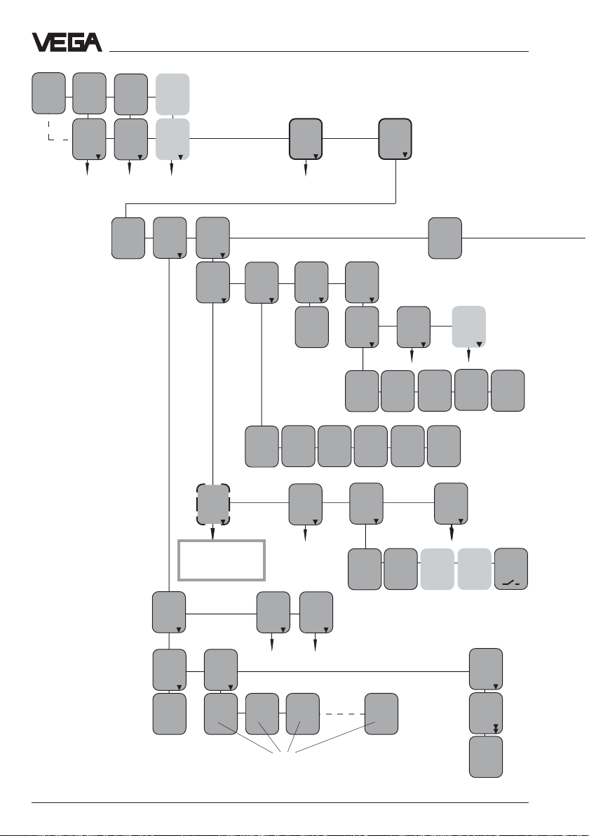
Set-up - Adjustment with MINICOM or VEGAMET
MST1-3
xx,x
xx,x
TAG -
TAG -
No. 1
No. 2
%
xx,x
AC
xx,x
Param.
TAGNo. 1
see page 68-69
%
xx,x
Param.
TAGNo. 2
Password
off
TAG No. 3
%
xx,x
Param.
TAGNo. 3
Edit
lin.
curves
Info
Input
info
VEGAMET 515 V - Menu plan
Configura
tion
Add´l
functions
B
see page 70-71
VEGAMET
Info
T ype
MET515
V
Programinfo
Program
info
xxxxxx
Serial
number
xxxx
xxxx
Instr.
addr.
1
Meas.
loop
info
TAG 1
TAG No. 1
Min
set at
%
0,0
Softw.
Vers .
01.13
97
Min
set at
0,000
bar
Softw.
Date
47/97
TAG 2
TAG No. 2
Language
English
like T A G 1
Max
set at
%
100,0
Param.
Vers.
5
TAG 3
TAG No. 3
Max
set at
bar
1,000
Parameter
Level
Curve
no.1
Add
Lin.point
x %
0,0
y V%
0,0
Input
no.1
II
continue in
MINICOM-menu
on page 74
Edit
curve
no.1
x 0 %
0,0
y 0 V%
0,0
Input
no.2
like input 1
Curve
Curve
no.2
no.3
like LIN-curve 1
x 1 %
x 2 %
100,0
y 1 V%
100,0
100,0
y 2 V%
100,0
Index marker numbers (0...32)
Input
no.4
Sensortype
Radar
x32 %
y32 V%
100,0
100,0
Input
from
local
MET
Channel
no.
K1
Input
no.5
like input 4
Input
no.
undefined
Delete
Lin.point
x 0,0
y 0,0
delete
Delete
now ?
Actual
switch
status
72 VEGAPULS 51 V … 54 V
Page 73
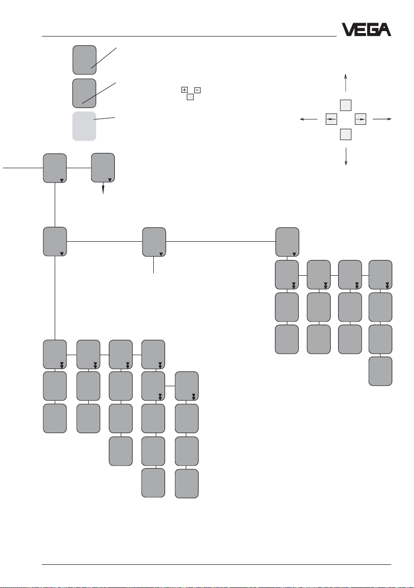
Set-up - Adjustment with MINICOM or VEGAMET
Reset
VEGAMET
Reset
configuration
TAG 1
to Default
Reset
OK?
Reset
Now!
OK?
act.
dist.
m
X,XX
fast
change
Yes
High
dust
level
Non
Service
only accessible with
service password
TAG 2
to Default
Reset
OK?
Reset
Now!
OK?
to
linked
applicat.
Delete
all
TAG´s?
Reset
OK?
Reset
Now!
OK?
Bolt print are the sensor or measured
value information which cannot be
modified in this position.
The menu points in white letters
can be modified with the or
key abd confirmed with the key .
Light grey menu fields are only
displayed if necessary (dependent
on the adjustments in the other
menus).
Reset
sensor
charac
Not available with VBUS
sensors (sensors with
digital output signal)
to
single
meas.
Reset
TAG 1
Delete
T AG 1?
Reset
OK?
Reset
Now!
OK?
OK
Reset
TAG 2
Delete
T AG 2?
Reset
OK?
Reset
Now!
OK?
With these keys you move in
the menu field to the left, right,
top and bottom.
Reset
lin.
curves
Reset
curve
no.1
Reset
OK?
Reset
Now!
OK?
Reset
curve
no.2
Reset
OK?
Reset
Now!
OK?
ESC
OK
Reset
curve
no.3
Reset
OK?
Reset
Now!
OK?
Reset
all
curves
Delete
all
curves
?
Reset
OK?
Reset
Now!
OK?
VEGAPULS 51 V … 54 V 73
Page 74

MINICOM - Menu plan
Set-up - Adjustment with MINICOM or VEGAMET
Sensor
m(d)
4.700
Parameter
Sensor
optimize
Sensor
Tag
ULTRAS
H
2.)
Sensor
optimize
Meas.
Enviro
nment
Operating
range
Begin
m (d)
0.30
PULS52
V
When switching on, the sensor
type and the software version
1.00
are displayed for a few seconds.
I
from the menu of the
signal conditioning
instrument VEGAMET
on page 70
Meas.
Condit
ions
End
m (d)
5.00
Measur
ing in
tube
Meas.
dist.
m (d)
4.700
Correc
tion
Now!
OK?
7.)
False
echo
memory
New
echo
learn
Meas.
dist.
m (d)
0.00
echo
learn
Now!
OK ?
learning
runs!
update
memory
Meas.
dist.
m (d)
0.00
update
memory
Now!
OK ?
learning
runs!
delete
memory
delete
memory
Now!
OK ?
deleting
runs!
3.)
Condit
ion
Liquid
fast
change
No
agitat
ed sur
face
No
Foaming
prod.
No
Heavy
dust
No
Low DK
product
No
large
angle
repose
No
9.)
Displ.
adjust
ment
0.0 %
at
m (d)
100.0%
at
m (d)
0
50
signal
Condit
ioning
Scaling
0 %
corres
ponds
100 %
Deci-
Prop.
corres
mal
ponds
0
point
50
888.8
to
Distance
Unit
m(d)
74 VEGAPULS 51 V … 54 V
outputs
Sensor
Displ.
Prop.
to
Distance
Page 75

Set-up - Adjustment with MINICOM or VEGAMET
Basic
Reset
Reset
Now!
OK ?
Reset
runs!
8.)
Distance
m (d)
4.700
Ampl.:
XX dB
S-N:
XX
dB
II
from the menu of the
signal conditioning
instrument VEGAMET
on page 72
Add’l
functions
Password
Off
Input
no. 1
Info
Sensor
Tag
Sensor
Basic
Reset
Reset
Now!
OK ?
Reset
runs!
Sensor
type
PULS52
V
Meas.
dist.
m
0.0
Foaming
Prod.
Non
fast
change
Yes
language
englisch
Serial
number
1094
0218
Bolt print are the sensor or measured
value information which cannot be
modified in this position.
The menu points in white letters
can be modified with the or
key abd confirmed with the
key.
Light grey menu fields are only
displayed if necessary (dependent
on the adjustments in the other
menus).
Meas.
Unit
m (d)
max.
Softw.
Softw.
Vers.
1.00
Date
10.03.
1998
range
m (d)
7.000
Disttance
m (d)
4.700
OK
Ampl.:
XX dB
S-N:
XX
dB
ESC
OK
With these keys you move in
the menu field to the left, right,
top and bottom.
VEGAPULS 51 V … 54 V 75
Page 76
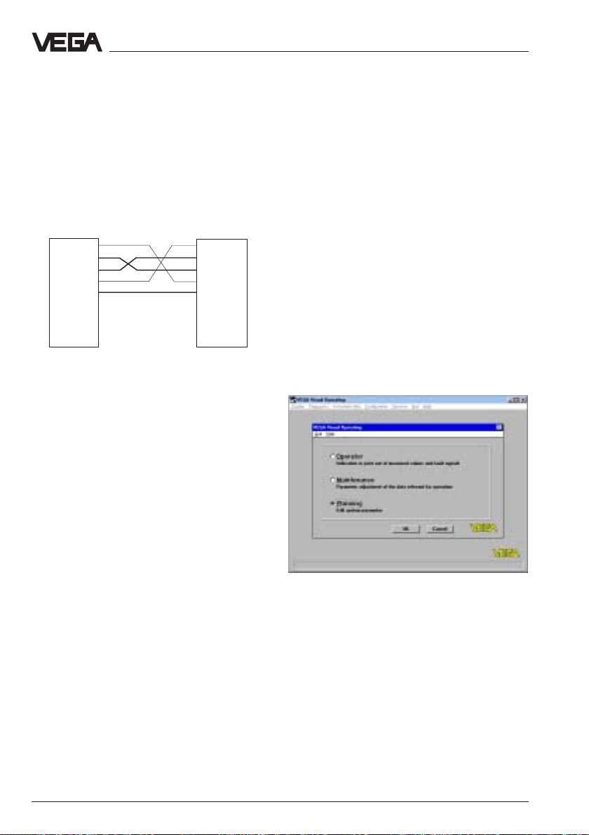
6.4 Adjustment with the PC on VEGALOG
For connection of the PC to the processing
system VEGALOG you require a standard
interface RS232 DTE-DTE (Data Terminal
Equipment) interface cable.
With this cable you connect the PC with the
processing system.
DTE DTE
DCD 1 1 DCD
RxD 2 2 RxD
TxD 3 3 TxD
DTR 4 4 DTR
GND 5 5 GND
--- 6 6 ---
--- 7 7 ---
--- 8 8 ---
--- 9 9 ---
Set-up - Adjustment with the PC on VEGALOG
The first set-up steps with the PC in
conjunction with the processing system
VEGALOG correspond to the adjustment in
chapter "
MINICOM
6.2 Adjustment with VEGAMET or
".
• Connect the standard output of your PC
with the standard RS232-interlink cable (9pole) to the processing system VEGALOG.
• Now switch on the power supply of the
processing system.
After approx. 1…2 minutes (selfcheck) the
meas. system consisting of processing
system and sensors is normally ready for
operation and the sensors indicate measured
values.
Via the signal and supply lines between
sensor and processing system also
adjustment signals are transmitted digitally
beside the measured values. The adjustment
program VVO can then communicate with the
processing system and all connected
sensors. In chapter "2.2 Configuration of
measuring systems" the connection of the PC
to the various meas. systems is shown.
Before starting with the set-up:Before starting with the set-up:
Before starting with the set-up:
Before starting with the set-up:Before starting with the set-up:
The many pictures, adjustment steps and
menus may be confusing but just carry out
the set-up with the PC step-by-step and you
will soon no more require the following pages.
When you want to enter or enquire something
this is marked in the following with a dot, e.g.
• Choose …
• Start …
• Click to …
• Now start the adjustment software VVO on
your PC.
• Choose in the initial screen with the arrow
keys or the mouse the point "
click to "
OKOK
OK
OKOK
".
Planning
" and
In the next window you are asked for the
identification.
76 VEGAPULS 51 V … 54 V
Page 77
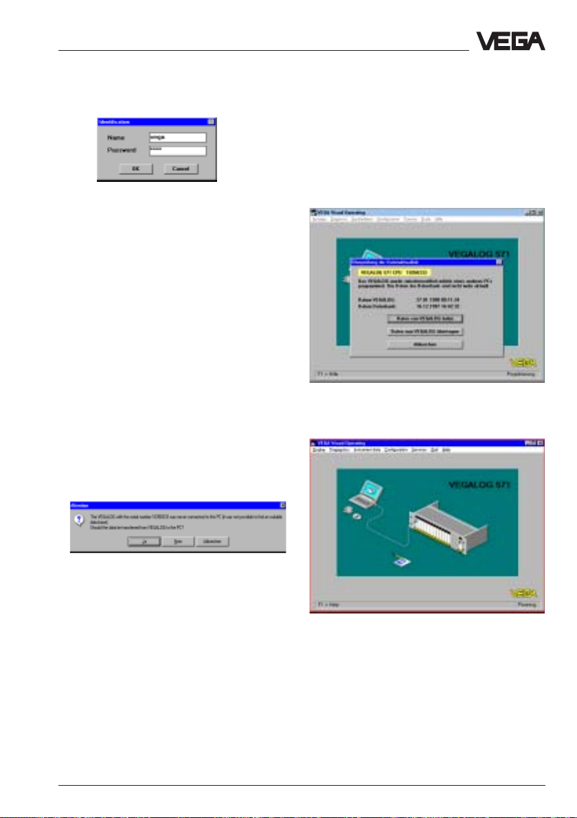
Set-up - Adjustment with the PC on VEGALOG
• Enter under name "
• Also enter under password
The adjustment program, called in the
following VVO, contacts the connected meas.
system/sensor …… and shows after a few
seconds if and with which meas. system/
sensors a connection exists.
Note:
If you do not get a sensor connection, check
the following:
- is the processing system powered with
supply voltage?
- do you erroneously use a wrong RS232cable instead of the VEGA RS-232connection cable?
If VVO (adjustment software) contacts the
processing system for the first time, you are
asked if the data should be transferred from
the processing system to the PC.
VEGAVEGA
VEGA
VEGAVEGA
".
VEGAVEGA
"
VEGA
VEGAVEGA
".
When you connect VVO to a VEGALOG
where data have been already saved, a
message is displayed whether you want to
transfer the saved data from the PC to
VEGALOG or whether the data of VEGALOG
should be transferred to the PC.
• Click to "
windowwindow
window.
windowwindow
OKOK
OK
", and you are in the
OKOK
main menumain menu
main menu
main menumain menu
YY
• Click to "
VEGAPULS 51 V … 54 V 77
eses
Y
es
"
YY
eses
The preadjusted identification can be
modified later in the menu "
gram/User access
" (see page 47).
Configuration/Pro-
Page 78
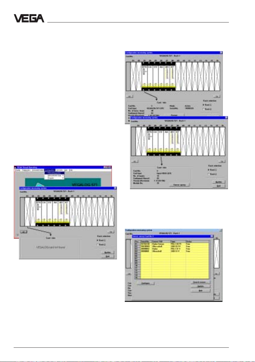
Configuration
The adjustment of a radar sensor on a
VEGALOG with the PC generally correponds
to the adjustment of a radar sensor on the
signal conditioning instrument, like in chapter
"
6.2 Adjustment with PC on VEGAMET
The difference is just in the higher
configuration requirement of VEGALOG. A
number of possible sensor inputs and signal
outputs as well as various processing
routines must be coordinated. First of all it
must be defined which sensor (input) whould
be processed where and how.
Configuration Info
".
Set-up - Adjustment with the PC on VEGALOG
• Choose the menu "
Measuring systemMeasuring system
Measuring system
Measuring systemMeasuring system
You are in the menu "
system
", where a picture of the connected
VEGALOG is shown on the PC.
• Click to an individual card and you get at
the bottom of the window a "
Configuration/Configuration/
Configuration/
Configuration/Configuration/
"
Configuration/Measuring
Card-Info
".
• Click in the card info window of your EV-
You get a survey of the sensors connected to
the card.
input card Vinput card V
card (
input card VBUS) to "
input card Vinput card V
Sensor surveySensor survey
Sensor survey
Sensor surveySensor survey
".
78 VEGAPULS 51 V … 54 V
Page 79

Set-up - Adjustment with the PC on VEGALOG
Create new measurement loop
• Choose the menu "
Measurement loop/NewMeasurement loop/New
Measurement loop/New"
Measurement loop/NewMeasurement loop/New
window "
the point "
Create new measurement loop
a new applicationa new application
a new application
a new applicationa new application
Configuration/Configuration/
Configuration/
Configuration/Configuration/
and confirm in the
" with "
OKOK
OK
OKOK
• Choose as parameter "
and as application "
• Click to "
"
".
• Choose "
"
• Click to "
After a few seconds the menu window
"
Create new measurement loop - Sensor
configuration
ContinueContinue
Continue
ContinueContinue
Standard level measurementStandard level measurement
Standard level measurement" and
no optionsno options
no options
no optionsno options
Standard level measurementStandard level measurement
ContinueContinue
Continue
ContinueContinue
"
" opens.
Level measurementLevel measurement
Level measurement
Level measurementLevel measurement
Pulse-RadarPulse-Radar
Pulse-Radar
Pulse-RadarPulse-Radar
"
".
"
"
You are in the menu window "
measurement loop - Application
parameter parameter
parameter (level, gauge or distance) and the
parameter parameter
sensor typesensor type
sensor type (pulse radar for radar).
sensor typesensor type
VEGAPULS 51 V … 54 V 79
Create new
". Choose the
• Click to "
Sensor coordinationSensor coordination
Sensor coordination
Sensor coordinationSensor coordination
"
Page 80
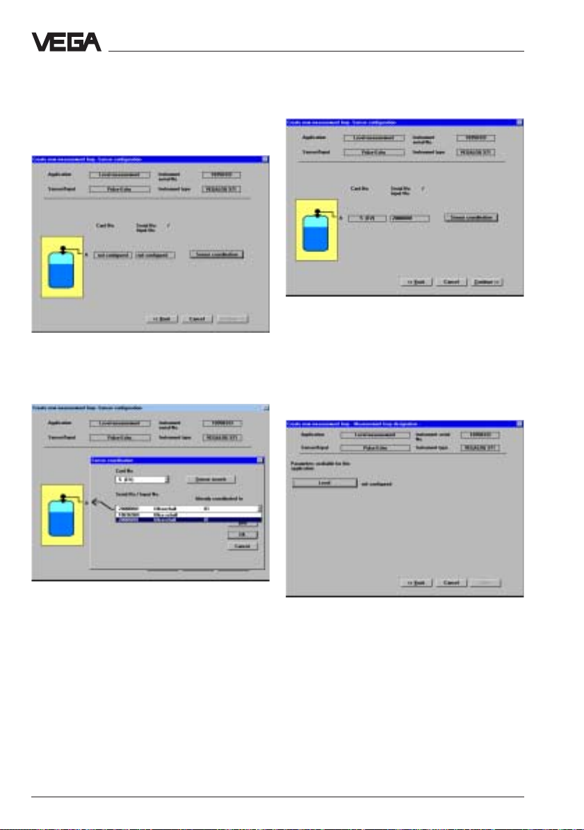
Set-up - Adjustment with the PC on VEGALOG
The small menu window "
opens.
• Choose the serial number of the sensor
you want to coordinate and confirm with
OKOK
"
OK
".
OKOK
Sensor coordination
"
The menu window
"Create new measurement
loop - Measurement loop designation"
Enter:
– a meas. loop no.
– a measurement loop description
– and coordinate to your sensor one or
several output signals.
opens.
• Click in the menu window "
measurement loop - Sensor configuration
ContinueContinue
to "
Continue
ContinueContinue
• Click in the menu window "
"
measurement loop - Measurement loop
designation"
80 VEGAPULS 51 V … 54 V
to
LevelLevel
"
Level"
LevelLevel
Create new
Create new
"
• E.g. configurate a current output, by
clicking to "
In the menu window "Configure current
output" you choose in your VEGALOG a
current output card and coordinate one or
several sensor outputs to the sensor.
Current outputCurrent output
Current output
Current outputCurrent output
".
Page 81

Set-up - Adjustment with the PC on VEGALOG
• Confirm your adjustment with "
you are again in the window "
OKOK
OK
OKOK
Create new
measurement loop - Measurement loop
designation
"
", and
• Click to "
are again in the intial menu.
You have carried out the special additional
configuration adjustments in conjunction with
a VEGALOG.
Congratulation!
In the menu "
systemsystem
system"
systemsystem
configured:
QuitQuit
Quit" and after a few seconds you
QuitQuit
Configuration/MeasuringConfiguration/Measuring
Configuration/Measuring
Configuration/MeasuringConfiguration/Measuring
you can see that a sensor is
• Confirm your adjustments with "
VEGAPULS 51 V … 54 V 81
OKOK
OK
OKOK
".
Now you have to carry out the parameter
adjustment.
The parameter adjustment is nearly identical
with the parameter adjustment in chapter
Adjustment with PC on VEGAMET"
"6.2
.
Page 82

Parameter adjustment
In the menu "
adjustment
sensor adjustments.
Adjustment
• Choose the menu
Instrument data/Parameter adjustmentInstrument data/Parameter adjustment
"
Instrument data/Parameter adjustment
Instrument data/Parameter adjustmentInstrument data/Parameter adjustment
and then the sensor for which you want to
carry out the parameter adjustment.
In the heading of the opening menu window
you now see the previously adjusted
measurement loop name and the
measurement loop description.
When you have only configured one sensor
on the signal conditioning instrument,
naturally only one sensor is available.
Instrument data/Parameter
" you carry out all important
Set-up - Adjustment with the PC on VEGALOG
",
You can carry out the Min./Max.-adjustment
"with medium"
real level) or
considering the real level, i.e. also with empty
vessel).
Generally you will carry out the adjustment
without medium, so you are completely independent of the actual vessel filling.
When you want to carry out the adjustment
with medium, you have to carry out the min.
adjustment with emptied (also partly
emptied) vessel and the max. adjustment
with filled (also partly filled) vessel.
It is hence comfortable and quick to carry out
the adjustment without medium like in the
example.
(adjustment by means of the
"without medium"
(without
• Choose "
• Choose in the following window if you want
to carry out the adjustment in metres (m) or
in
• Enter a
level and the appropriate
%.
In the example the 0 % filling is at a level
distance of 3,400 m and the 100 % filling at a
level distance of 0,500 m.
• First choose "
• Then click in the menu window "Adjustment"
Min / Max - adjustmentMin / Max - adjustment
to "
Min / Max - adjustment
Min / Max - adjustmentMin / Max - adjustment
82 VEGAPULS 51 V … 54 V
AdjustmentAdjustment
Adjustment
AdjustmentAdjustment
"
"
no (adjustment without medium)no (adjustment without medium)
no (adjustment without medium)
no (adjustment without medium)no (adjustment without medium)
Feet
(ft).
distance distance
distance for the upper and lower
distance distance
filling degree filling degree
filling degree in
filling degree filling degree
"
Page 83

Set-up - Adjustment with the PC on VEGALOG
together, the possible meas. error increases.
It is hence suitable when you carry out the
adjustment at 0 % and at 100 %.
• Confirm the adjustments with "
are again in the menu window "
• Click in the menu window "Adjustment" to
QuitQuit
"
Quit
".
QuitQuit
You are now again in the menu window "
strument data parameter adjustment
Hence the sensor electronics has two
characteristics points, one at MIN and one at
MAX, out of which a linear proportionality
between level distance and the percentage
filling of a vessel is generated.
The characteristics points however must not
be at 0 % and 100 % however the difference
should be as large as possible (e.g. at 20 %
and at 80 %). The min. distance between the
characteristics points for the min./max.
adjustment should be 50 mm.
OKOK
OK
", and you
OKOK
Adjustment
In-
".
In the menu "
Instrument data/Parameter
adjustment/Conditioning/Linearisation
can enter later if necessary another linear
dependence between the level distance and
the percentage filling degree (see later
subpoint linearisation).
Conditioning
".
• Click in the menu window "
parameter adjustment
The menu window "
• Click to "
In the menu "
0 % and 100 %-values of the parameter and
their unit. Hence you inform the sensor, e.g.
that at 0 % filling there are still 45,5 litres and
at 100 % filling1200 litres in the vessel.
The sensor indication shows in case of empty
vessel 45,5 litres (0 %) and in case of full vessel
1200 litres (100 %).
ScalingScaling
Scaling
ScalingScaling
Conditioning
".
Scaling
" you enter the actual
Instrument data
ConditioningConditioning
" to "
Conditioning
ConditioningConditioning
" opens.
" you
".
When the characteristics points are too close
VEGAPULS 51 V … 54 V 83
Page 84
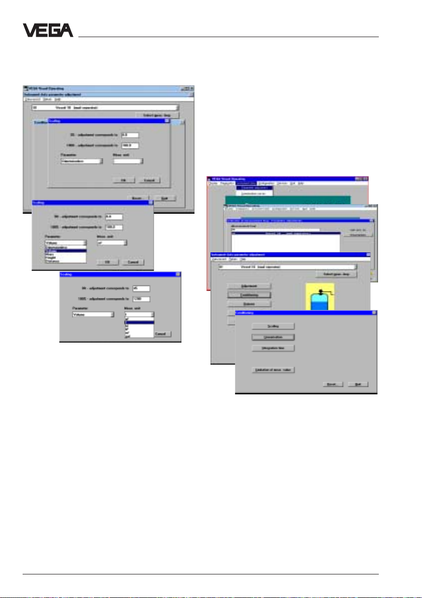
Set-up - Adjustment with the PC on VEGALOG
Linearisation
The relation of level and filling volume is
described with so called linearisation curves.
If in your vessel there is another than a linear
dependence between the level ("
value
" of the level) and the filling volume
("
Linearised
"), choose the menu "
percentage
Instrument
data/Parameter adjustment/Conditioning"
As parameter you can choose
(figures),
and coordinate to the parameter the
appropriate unit (e.g. litres, hl). The sensor
indication then displays the figure in the
selected paramenter and unit.
• Save the adjustments in the menu "
The adjustments are now transferred to the
sensor and you are again in the menu
window "
• Click in the menu window "
• Click in the menu window "
volume, mass, height
OKOK
with "
OK
".
OKOK
Conditioning
QuitQuit
"
Quit
"
QuitQuit
".
parameter adjustment"
84 VEGAPULS 51 V … 54 V
"dimensionless
and
Conditioning
Instrument data
QuitQuit
to "
Quit"
QuitQuit
distance"
Scaling
" to
• Click in the menu window "
the menu point "
"
In the menu window "
that "
Linear
the dependence between the percentage
value of the filling volume and the value of the
level is linear.
Beside the two given linearisation curves
"
cylindrical tank
also enter six "
• Click to "
then to "
LinearisationLinearisation
Linearisation
LinearisationLinearisation
" is preadjusted. This means that
" and "
user programmable curves
User programmable curveUser programmable curve
User programmable curve
User programmable curveUser programmable curve
EditEdit
Edit
".
EditEdit
Conditioning
".
Linearisation
spherical tank
" you see
" to
" you can
".
" and
Page 85
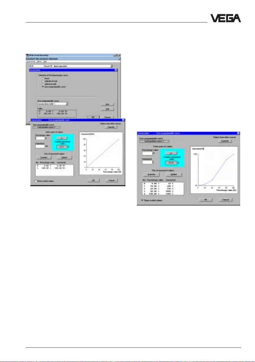
Set-up - Adjustment with the PC on VEGALOG
Gauging by litres
In the characteristics of the following figure
you see five linearisation points or value pairs
(0, 1, 2, 3, and 4). There is always a linear
interpolation between the linearisation points.
Linearisation point 0 is at 0 % filling
(
percentage value [%]
to an actual distance to the product surface
of 3,400 m in the example (empty vessel).
The volume value is 45,5 litres (rest filling of
the vessel).
), which corresponds
• Click at the bottom left side to "
scaled valuesscaled values
scaled values
scaled valuesscaled values
displayed on the y-axis.
First of all a linear relation (straight line) is
displayed.
In the field "
level in percent of the adjusted meas. range
(meas. window) is displayed.
The user programmable curve is generated
with linearisation points, the so called value
pairs. One value pair consists of "
(percentage value of the filling) and
"
Percentage value
level relating to the adjusted meas. range).
If the linearisation points or value pairs of
your vessel are not known to you, you have
to gauge the vessel by litres.
VEGAPULS 51 V … 54 V 85
", to have the adjusted unit
Transfer measured value
" (percentage value of the
ShowShow
Show
ShowShow
" the actual
Linearised
Linearisation point 1 is at a level of 20 %
(20 % of the meas. distance of
0,500 m … 3,400 m). At 20 % filling there are
in our example 100 litres in the vessel.
Linearisation point 2 is at a level of 40 %. At
this level there are 250 litres in the vessel.
Linearisation point 3 is at a level of 80 %,
where 1000 litres are in the vessel.
Linearisation point 4 is at a level of 100 %
"
(product distance 0,500 m), where 1200 litres
are in the vessel.
You can enter max. 32 linearisation points
(value pairs) per linearisation curve.
Page 86

Set-up - Adjustment with the PC on VEGALOG
• Quit the menu with "
• Confirm the message with "
individual linearisation curve will be saved
in the sensor.
Again in the menu window "
can enter with the menu point "
time
" a measured value integration. This is
useful for fluctuating product surfaces to
avoid a permanently changing measured
value indication and output.
As a standard feature an integration time of
0 seconds is adjusted.
• Quit the menu with "
• Quit the menu window "Instrument data
parameter adjustment" with "
Outputs
• Choose in the main menu window "
ment data/Parameter adjustmentment data/Parameter adjustment
ment data/Parameter adjustment
ment data/Parameter adjustmentment data/Parameter adjustment
the menu point "
OKOK
OK
OKOK
OKOK
OK
OKOK
OutputsOutputs
Outputs
OutputsOutputs
".
OKOK
OK
", and your
OKOK
Conditioning
Integration
".
OKOK
OK
".
OKOK
".
" you
Instru-Instru-
Instru-
Instru-Instru-
", and then
SaveSave
Save
SaveSave
".
Current outputCurrent output
Current output
Current outputCurrent output
QuitQuit
Quit
QuitQuit
" to adjust the signal
".
• Click to "
mode of the 0/4…20 mA output signal.
• If you have made adjustments in the menu
window "Current output", click to
"
• If you want to keep the adjustments
unchanged, click to "
You are now again in the menu window
"
Outputs
measured value"
indication or probably additional indicating
instruments connected to VEGALOG (see
also page 59 right column).
• Click in the menu window "
". With the menu point
QuitQuit
"
Quit" and you are in the menu window
QuitQuit
you scale the sensor
"Display of
Outputs
" to
"In-
strument data parameter adjustment"
• Click in the menu window
You are in the menu window "
86 VEGAPULS 51 V … 54 V
Outputs
".
parameter adjustment"
"Instrument data
again to "
QuitQuit
Quit".
QuitQuit
Page 87

Set-up - Adjustment with the PC on VEGALOG
Sensor optimisation
In the menu "
carry out special optimising adjustments on
the sensors and optimise e.g. by means of
the echo curve the installation position of the
sensor.
Meas. environment
• Choose the menu
Instrument data/Parameter adjustmentInstrument data/Parameter adjustment
"
Instrument data/Parameter adjustment
Instrument data/Parameter adjustmentInstrument data/Parameter adjustment
and the sensor for which the parameter
adjustment should be carried out
• Choose in the menu window "
data parameter adjustment
Sensor optimisationSensor optimisation
"
Sensor optimisation
Sensor optimisationSensor optimisation
menu window
optimisation"
• First click to "
Sensor optimisation
" you can
Instrument
" the menu point
", and click in the
"Sensor choice for sensor
Sensor ASensor A
to "
Sensor A
Sensor ASensor A
Meas. environmentMeas. environment
Meas. environment
Meas. environmentMeas. environment
"
"
".
The window "
• Wählen Sie "
Meas. environment
ArbeitsbereichArbeitsbereich
Arbeitsbereich
ArbeitsbereichArbeitsbereich
"
" opens.
With the menu point "
menu window "
define the operating range of the sensor
deviating from the "
As a standard feature the operating range
corresponds otherwise to the Min-/Maxadjustment.
VEGAPULS 51 V … 54 V 87
Operating range
Meas. environment
Min/Max-adjustment
" in the
" you can
".
Page 88

Set-up - Adjustment with the PC on VEGALOG
Generally it is useful to choose the operating
range approx. 5 % larger than the meas.
range.
In the example the meas. range was
adjusted by the min./max. adjustment to
0,500 … 3,400 m (min.-adjustment 0,500 m,
max.-adjustment 3,400 m).
You would then adjust the operating range to
0,400 … 3,500 m.
• Save the adjustments with "
• Click in the menu window "
environment
• In the menu window "
click to the options corresponding to your
application.
Measuring conditionsMeasuring conditions
" to "
Measuring conditions
Measuring conditionsMeasuring conditions
OKOK
OK
"
OKOK
Meas.
Measuring conditions
".
Echo curve
With the menu point "
have a look to the course and the strength of
the detected radar echo.
If you have to expect strong false echoes
due to vessel installations, a correction of the
installation position (if possible) can help by
monitoring the echo curve, to localize and
reduce the size of the false echoes.
"
Echo curve
" you can
".
OKOK
OK
OKOK
" to "
".
".
QuitQuit
Quit
QuitQuit
Meas.
".
Sensor
Proceed like in chapter "Echo curve" onProceed like in chapter "Echo curve" on
Proceed like in chapter "Echo curve" on
Proceed like in chapter "Echo curve" onProceed like in chapter "Echo curve" on
page 57…59.page 57…59.
page 57…59.
page 57…59.page 57…59.
• Confirm with "
After a few seconds of saving during which
the adjustments are permanently saved in
the sensor, you are again in the window
"
Meas. environment
• Click in the menu window "
environment
You are again in the menu window "
optimisation
88 VEGAPULS 51 V … 54 V
Page 89

Set-up - Adjustment with the PC on VEGALOG
Meas. loop data
• Choose in the main menu window "
ment data/Parameter adjustmentment data/Parameter adjustment
ment data/Parameter adjustment
ment data/Parameter adjustmentment data/Parameter adjustment
in the window "Instrument data parameter
adjustment" to "
• Click to "
Input No. AInput No. A
"
Input No. A
Input No. AInput No. A
detailed information on your measuring
system in the information windows.
Meas. loop dataMeas. loop data
Meas. loop data
Meas. loop dataMeas. loop data
ApplicationApplication
Application
ApplicationApplication
" and "
",
VEGALOGVEGALOG
VEGALOG
VEGALOGVEGALOG
" and click
".
", to get
Instru-Instru-
Instru-
Instru-Instru-
• Close the information windows.
• Quit the menu "
• Click in the menu window
parameter adjustment"
You are now again in the main menu window.
Change COM-interface
In the menu "
Communication
parameters of your PC or change the used
DOM-port.
Meas. loop data
".
"Instrument data
QuitQuit
to "
Quit
".
QuitQuit
Configuration/Program/
" you can adjust the interface
Display of measured value
See page 60
Simulation
See page 61
VEGAPULS 51 V … 54 V 89
Page 90

Backup
• Click to
Services/Backup/Signal conditioningServices/Backup/Signal conditioning
"
Services/Backup/Signal conditioning
Services/Backup/Signal conditioningServices/Backup/Signal conditioning
instrumentsinstruments
instruments
instrumentsinstruments
"
Set-up - Adjustment with the PC on VEGALOG
Saved sensor data can be later transferred
to other sensors.
E.g. if you have a system with several of the
same storage tanks and identical sensors, it
is sufficient to configure one sensor, to save
the adjustments and transfer them to the
other sensors.
Naturally it is also possible that data of a
processing system VEGALOG are
transmitted to a VEGALOG.
In the menu window "
with the serial number is displayed. You can
save the data of VEGALOG individually or in
groups with all adjustments in a directory of
your choice on the PC. You can also add
short backup notes.
In the same way you save the adjustments of
the sensors:
Backup
" the VEGALOG
• Choose the menu "
configuration/Signal conditioningconfiguration/Signal conditioning
configuration/Signal conditioning
configuration/Signal conditioningconfiguration/Signal conditioning
instrumentsinstruments
instruments
instrumentsinstruments
In this menu window you choose in the yellow
window cutout a VEGALOG (or a sensor),
which should be overwritten with the
adjustments of another VEGALOG.
Choose in the field "
serial number of the VEGALOG, of which you
want to transfer the adjustments. With
"
Restore to
adjustments to the VEGALOG, which you
have selected in the yellow window cutout.
" you transfer these VEGALOG-
Services/RestoreServices/Restore
Services/Restore
Services/RestoreServices/Restore
"
Selection of backups
" the
90 VEGAPULS 51 V … 54 V
Page 91

Notes
VEGAPULS 51 V … 54 V 91
Page 92

Notes
92 VEGAPULS 51 V … 54 V
Page 93

Notes
VEGAPULS 51 V … 54 V 93
Page 94

Notes
94 VEGAPULS 51 V … 54 V
Page 95

Notes
VEGAPULS 51 V … 54 V 95
Page 96

1
VEGA Grieshaber KG
Am Hohenstein 113
D-77761 Schiltach
Phone (0 78 36) 50 - 0
Fax (0 78 36) 50 - 201
e-mail vega@vega-g.de
ISO 900
The statements on types, application, use and operating conditions of
the sensors and processing systems correspond to the actual
knowledge at the date of printing.
Technical data subject to alteration
2.21 755 / March‘98
 Loading...