

Page 1
Operating Instructions
VEGAPULS 51K … 54K
®
4 … 20 mA; HART
compact sensor
Page 2

Contents
Safety information ........................................................................ 3
Note Ex area ................................................................................ 3
1 Product description .................................................................. 4
1.1 Function ................................................................................. 4
1.2 Application features ............................................................. 5
1.3 Adjustment ............................................................................ 6
2 Types and v ersions ................................................................... 8
2.1 Overvie w .............................................................................. 8
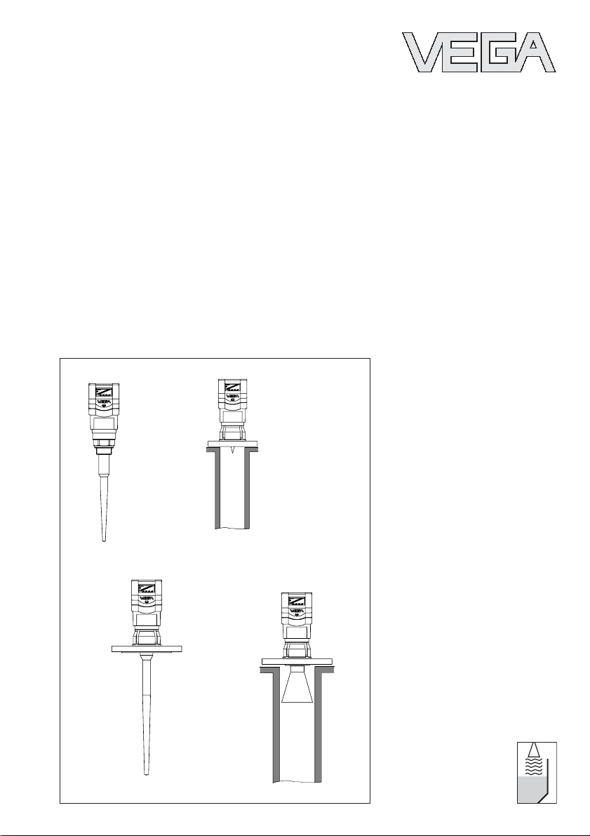
2.2 Antennas ............................................................................. 10
3 Mo unting and in stalla tion ..................................................... 11
3.1 General installation instructions ........................................ 11
3.2 Measurement of liquids ..................................................... 12
3.3 Measurement in standpipe (surge or bypass tube) ...... 14
3.4 False echoes ...................................................................... 21
3.5 Common installation mistakes ........................................... 23
Contents
4 Electrical connection .............................................................. 25
4.1 Connection and connection cable .................................... 25
4.2 Connecting the sensor ...................................................... 27
4.3 Connecting of the external indicating instrument
VEGADIS 50 ....................................................................... 31
4.4 Configuration of measuring systems ............................... 32
5 Set-up ........................................................................................ 40
5.1 Adjustment media .............................................................. 40
5.2 Adjustment with PC ............................................................ 40
5.3 Adjustment with adjustment module MINICOM ............... 42
5.4 Adjustment with HART® handheld ................................... 48
6 Diagnostics............................................................................... 50
6.1 Simulation ............................................................................ 50
6.2 Error codes ........................................................................ 50
2 VEGAPULS 51K … 54K
21750-EN-031222
Page 3

Contents
7 Technic al data .......................................................................... 51
7.1 Technical data ..................................................................... 51
7.2 Approvals ........................................................................... 58
7.3 Dimensions ......................................................................... 59
Supplement ..................................................................................... 63
Safet y Manual ................................................................................. 63
1 General ............................................................................... 63
1.1 Validity ................................................................................. 63
1.2 Area of application ............................................................... 63
1.3 Relevant standards ............................................................. 63
1.4 Determination of safety-related characteristics.................. 64
2 Planning .............................................................................. 65
2.1 Low demand mode ............................................................... 65
2.2 High demand or continuous mode ....................................... 65
2.3 General ................................................................................ 65
3 Set-up ................................................................................. 66
3.1 Mounting and installation ..................................................... 66
3.2 Adjustment instructions and parameter adjustment ........... 66
3.3 Configuration of the processing unit ................................... 66
4 Reaction during operation and in case of failure ............. 67
5 Recurring function test ....................................................... 67
6 Safety-related characteristics ........................................... 68
SIL declaration of conformity .................................................... 69
CE declaration of conformity ..................................................... 70
Safety information
Please read this manual carefully, and also take
note of country-specific installation standards
(e.g. the VDE regulations in Germany) as well
as all prevailing safety regulations and accident prevention rules.
For safety and warranty reasons, any internal
Note Ex area
Please note the attached safety instructions
containing important information on installation
and operation in Ex areas.
These safety instructions are part of the operating instructions manual and come with the Ex
approved instruments.
work on the instruments, apart from that involved in normal installation and electrical connection, must be carried out only by qualified
VEGA personnel.
21750-EN-031222
VEGAPULS 51K … 54K 3
Page 4
1 Product description
Product description
1.1 Function
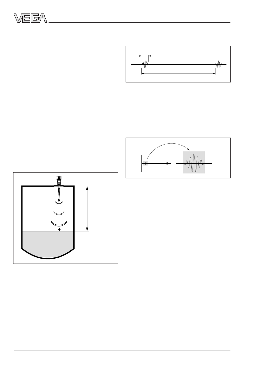
Radio detecting and ranging: Radar.
VEGAPULS radar sensors are used for noncontact, continuous distance measurement.
The measured distance corresponds to a
filling height and is outputted as level.
Measuring principle:
emission – reflection – reception
Extremely small 5.8 GHz radar signals are
emitted from the antenna of the radar sensor
as short pulses. The radar pulses reflected
by the sensor environment and the product
are received by the antenna as radar echoes. The running period of the radar pulses
from emission to reception is proportional to
the distance and hence to the level.
Meas.
distance
1 ns
278 ns
Pulse sequence
VEGAPULS radar sensors can achieve this
through a special time transformation procedure which spreads out the more than 3.6
million echo images per second into a quasi
slow-motion picture, then freezes and processes them.
tt
Time transformation
Hence, it is possible for the radar sensors to
process the slow-motion pictures of the sensor environment precisely and in detail in
cycles of 0.5 to 1 second without using timeconsuming frequency analysis (e.g. FMCW,
required by other radar techniques).
Virtually all products can be measured
Radar signals display physical properties
similar to those of visible light. According to
emission - reflection - reception
The radar pulses are emitted by the antenna
system as pulse packages with a pulse
duration of 1 ns and pulse intervals of
278 ns; this corresponds to a pulse package
frequency of 3.6 MHz. In the impulse intervals, the antenna system operates as a receiver. Signal running periods of less than
one billionth of a second must be processed
and the echo image evaluated in a fraction of
a second.
4 VEGAPULS 51K … 54K
the quantum theory, they propagate through
empty space. Hence, they are not dependent on a conductive medium (air), and they
spread out like light at the speed of light.
Radar signals react to two basic electrical
properties:
- the electrical conductivity of a substance
- the dielectric constant of a substance.
21750-EN-031222
Page 5
Product description
All products which are electrically conductive
reflect radar signals very well. Even slightly
conductive products provide a sufficiently
strong reflection for a reliable measurement.
All products with a dielectric constant ε
greater than 2.0 reflect radar pulses sufficiently (note: air has a dielectric constant ε
1). Signal reflectivity grows stronger with
r
r
increasing conductivity or increasing dielectric constant of the product. Hence, nearly all
substances can be measured.
%
50
40
30
20
10
5 %
5
0
2
0
25 %
4 6 8 12 14 16 18
10
40 %
20
ε
r
Reflected radar power dependent on the dielectric
constant of the measured product
With standard flanges of DN 50 to DN 250,
ANSI 2“ up to ANSI 10“ or G 1½ A and 1½“
NPT, the sensor antenna systems can be
adapted to various products and measuring
environments.
The high-quality materials can also withstand
extreme chemical and physical conditions.
The sensors deliver stable, reproducible
analogue or digital level signals with reliability
and precision and have a long useful life.
%
0,03
0,02
0,01
0
100 500 1000 1300 ˚C
0
0,018 %
0,023 %
Temperature influence: Temperature error absolutely
zero (e.g. at 500°C 0.018 %)
of
%
10
5
0
0
0,29 %
10
20 30 40 60
1,44 %
50
2,8 %
70 80 90 110 120 130 140
100
Pressure influence: Error with pressure increase very
low (e.g. at 50 bar 1.44 %)
VEGAPULS 50 sensors allow radar level
measurement in plants where it was hitherto
unthinkable because of high costs.
1.2 Application features
Applications
• level measurement of any liquid, limited in
solids.
• measurement also in vacuum
• all slightly conductive materials and all
substances with a dielectric constant > 2.0
can be measured
• measuring range 0 … 20 m.
Two-wire technology
• power supply and output signal on one
two-wire cable (Loop powered)
• 4 … 20 mA output signal or HART® output
signal.
3,89 %
bar
Continuous and accurate
Unaffected by temperature, pressure and
atmosphere content, VEGAPULS radar sensors measure quickly, accurately and continuously the levels of widely varying
products.
Rugged and abrasionproof
• non-contact
• high-resistance materials
Exact and reliable
• accuracy 1 mm.
• unaffected by noise, vapours, dusts, gas
compositions and inert gas stratification
• unaffected by varying density and temperature of the medium
• measurement in pressures up to 40 bar
and product temperatures up to 200 °C.
21750-EN-031222
VEGAPULS 51K … 54K 5
Page 6
Communicative
• integrated measured value display
• optional display module separate from
sensor
• adjustment with detachable adjustment
module, pluggable in the sensor or in the
external display
• adjustment with HART® handheld
• adjustment from PLC level with the PC
Approvals
• CENELEC, ATEX, PTB, FM, CSA, ABS,
LRS, GL, LR, FCC.
1.3 Adjustment
Every measurement setup is unique. For that
reason, every radar sensor needs some
basic information on the application and the
environment, e.g. which level means "empty“
and which level "full“. Beside this "empty and
full adjustment“, many other settings and
adjustments are possible with VEGAPULS
radar sensors.
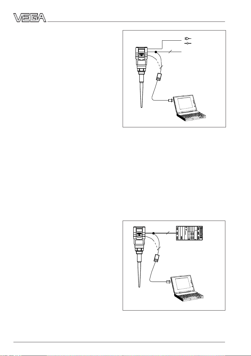
The adjustment and parameter setting of
radar sensors is carried out with
- the PC
- the detachable adjustment module MINICOM
- the HART® handheld
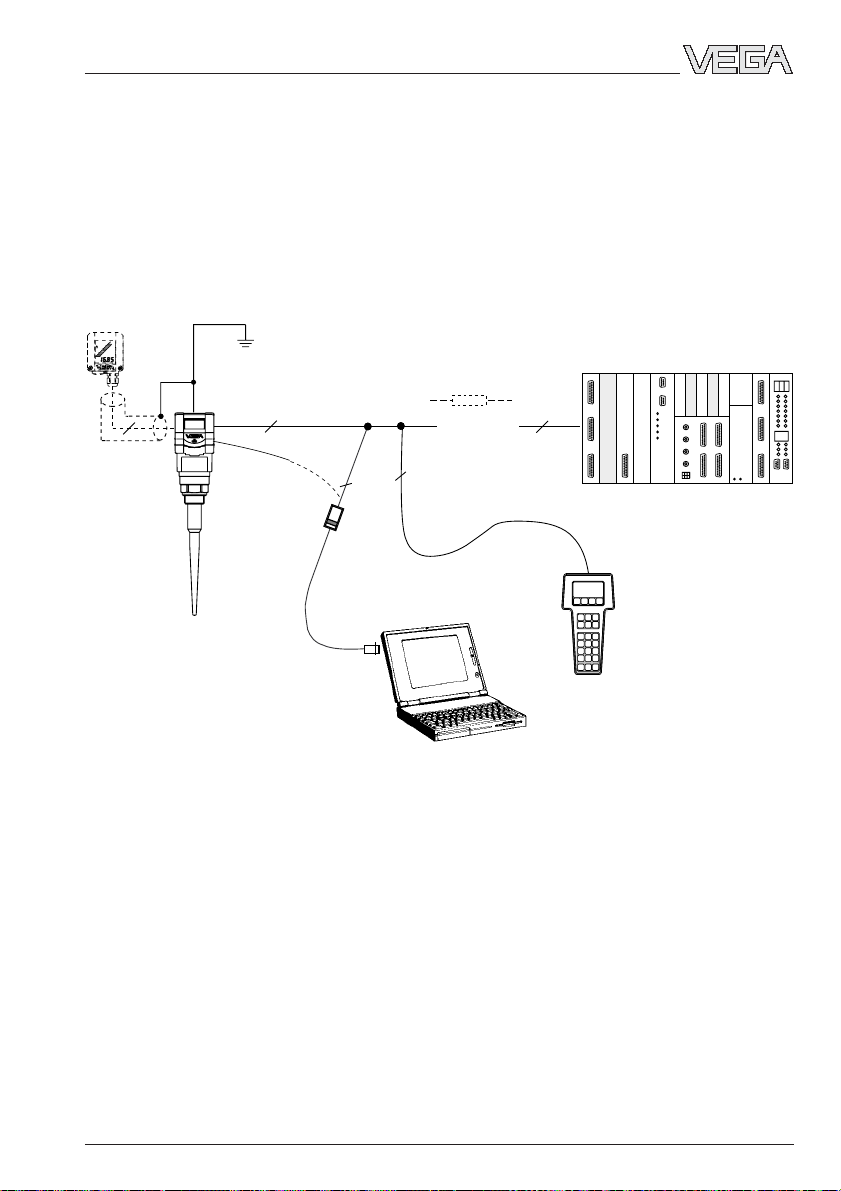
Product description
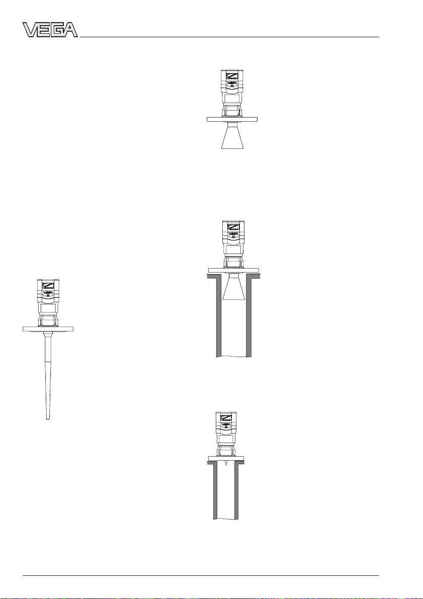
2
4 ...20 mA
2
Adjustment with the PC on the analogue 4 … 20 mA
signal and supply cable or directly on the sensor
(four-wire sensor)
The PC can be connected at any location in
the system or directly to the signal cable. It is
connected by means of the two-wire PC
interface converter VEGACONNECT 3 to the
sensor or the signal cable. The adjustment
and parameter data can be saved with the
adjustment software on the PC and can be
protected by passwords. On request, the
adjustments can be quickly transferred to
other sensors.
Adjustment with the PC
The set-up and adjustment of the radar sensors is generally done on the PC with the
adjustment software PACT
ware
TM.
The pro-
2
PLC
2
gram leads quickly through the adjustment
and parameter setting by means of pictures,
graphics and process visualisations.
Adjustment with the PC on the 4 … 20 mA signal and
supply cable or directly on the sensor (figure: a twowire sensor)
6 VEGAPULS 51K … 54K
21750-EN-031222
Page 7
Product description
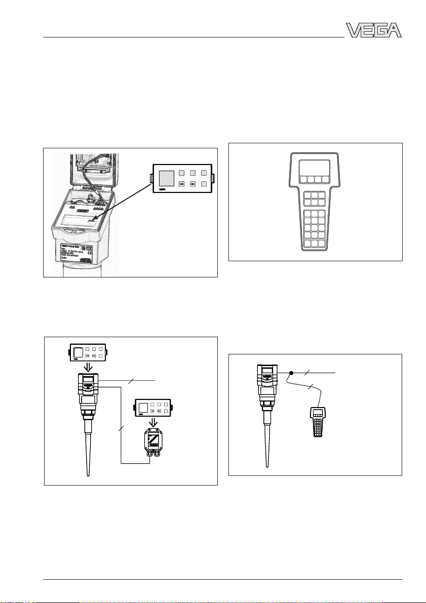
Adjustment with the adjustment module
MINICOM
With the small (3.2 cm x 6.7 cm) 6-key adjustment module with display, the adjustment
is carried out in clear text dialogue. The adjustment module can be plugged into the
radar sensor or into the optional, external
indicating instrument.
Tank 1
m (d)
12.345
Detachable adjustment module MINICOM
Unauthorised sensor adjustments can be
prevented by removing the adjustment module.
ESC
+
Tank 1
-
m (d)
12.345
OK
2
4 ... 20 mA
ESC
+
-
OK
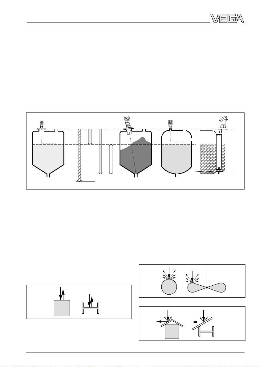
Adjustment with the HART® handheld
Series 50 sensors with 4 … 20 mA output
signal can also be adjusted with the HART
handheld. A special DDD (Data Device Description) is not necessary - the sensors can
be adjusted with the HART® standard menus
of the handheld.
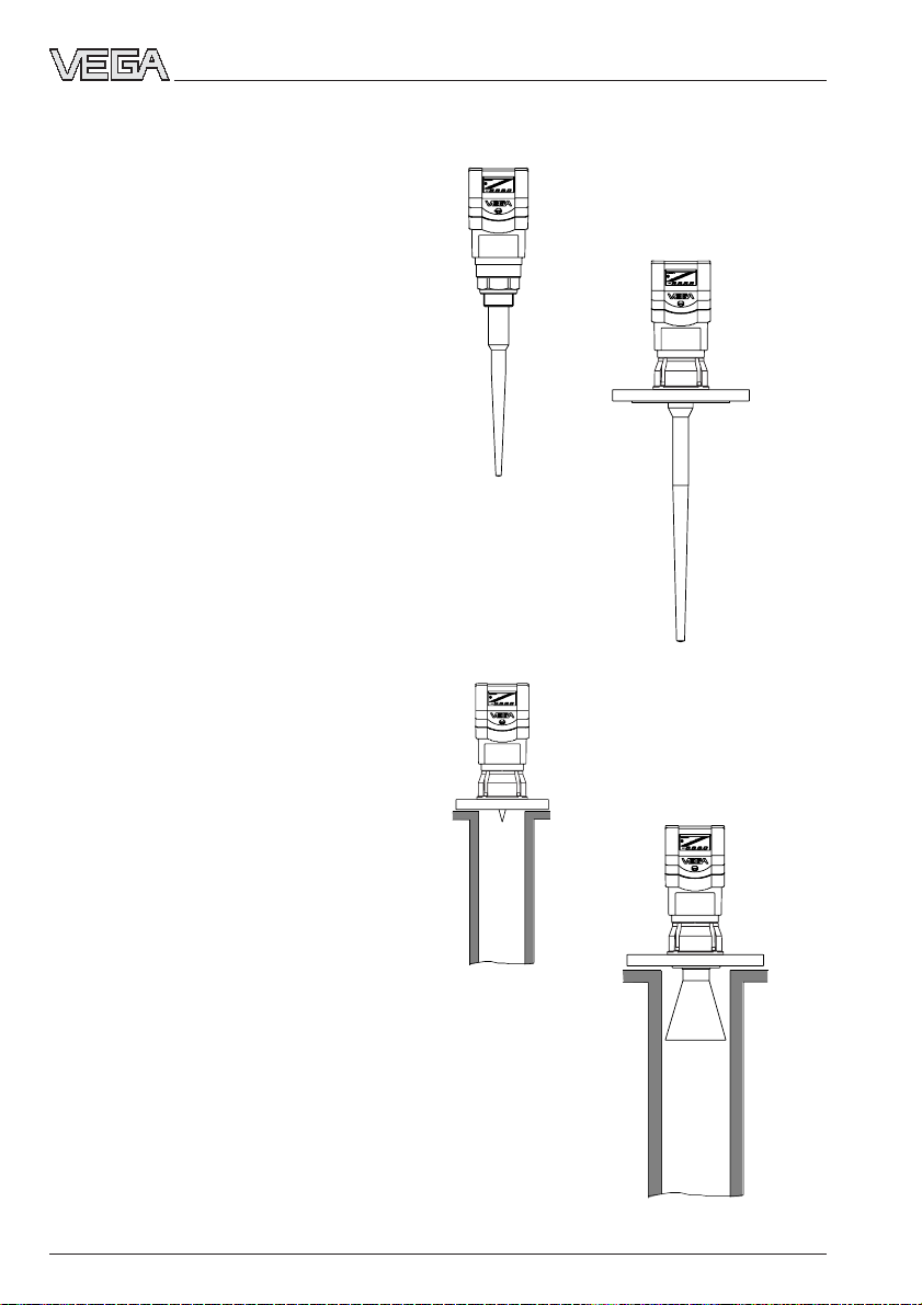
HART Communicator
HART® handheld
To make adjustments, simply connect the
HART® handheld to the 4 … 20 mA output
signal cable or insert the two communication
cables of the HART® handheld into the adjustment jacks on the sensor.
2
4 ...20 mA
2
®
ESC
+
Tank 1
-
m (d)
12.345
OK
4
HART® handheld on the 4 … 20 mA signal cable
Adjustment with detachable adjustment module. The
adjustment module can be plugged into the radar
sensor or into the external indicating instrument
VEGADIS 50.
21750-EN-031222
VEGAPULS 51K … 54K 7
Page 8
2 Types and versions
Types and versions
2.1 Overview
VEGAPULS series 50 sensors are a newly
developed generation of very compact, small
radar sensors. With modest space requirements, they were developed for short measuring distances of 0 … 20 m and for
standard applications such as storage tanks
and buffer tanks, but also for process vessels.
Due to their small housing dimensions and
process connections, the compact sensors
do your level monitoring inconspicuously, and
above all, at reasonable cost. With their integrated display and remarkable intelligence,
they bring the advantages of radar level
measurement to applications where previously, due to high cost, the advantages of
non-contact measurement had to be foregone.
VEGAPULS 50 radar sensors utilise two-wire
technology perfectly. The supply voltage and
the output signal are transmitted via one twowire cable. They provide an analogue
4 … 20 mA output signal as output or measuring signal.
VEGAPULS 51/52
VEGAPULS 54
(pipe antenna/
standpipe)
VEGAPULS 53
VEGAPULS 54
(pipe antenna/
standpipe)
8 VEGAPULS 51K … 54K
21750-EN-031222
Page 9

Types and versions
Features
General features
• Application preferably for liquids in storage tanks.
• Measuring range 0 … 20 m.
• Ex approved in Zone 1 (IEC) or Zone 1 (ATEX) classification mark
EEx ia [ia] IIC T6.
• Integrated measured value display.
Survey
VEGAPULS …
51K 52K 53K 54K
Signal output
- active (4 … 20 mA) • • • •
- passive (4 … 20 mA) • • • •
Voltage output
- two-wire technology (power
supply and signal output
via one two-wire cable) • • • •
- four-wire technology (power
supply separate from the signal
cable) • • • •
Process fitting
- G1½ A; 1½“ NPT • • – –
- DN 50; ANSI 2“ – – • •
- DN 80; ANSI 3“ – – • •
- DN 100; ANSI 4“ – – • •
- DN 150; ANSI 6“ – – • •
Adjustment
-PC • • • •
- adjustment module in the sensor • • • •
- adjustment module in external
indicating instrument • • • •
- HART® handheld • • • •
Antenna material
- PP/PVDF • – – –
- PPS/StSt • – – –
- PTFE/PVDF – • – –
- PTFE/StSt – • – –
- PTFE – – • –
- StSt/PTFE – – – •
- Hastelloy C22/PTFE – – – •
21750-EN-031222
VEGAPULS 51K … 54K 9
Page 10
Types and versions
2.2 Antennas
The antenna is the eye of the radar sensor.
The shape of the antenna, however, doesn’t
give a casual observer the slightest clue on
how carefully the antenna geometry must be
adapted to the physical properties of electromagnetic waves. The geometrical form determines focal properties and sensitivity - the
same way it determines the sensitivity of a
unidirectional microphone.
Four antenna systems are available for different applications and process requirements.
Beside having its own unique focusing characteristics, each system differs in its chemical and physical properties.
Rod antenna
Rod antennas with high chemical resistance require only the
very smallest flange diameters
(DN 50). The antenna rod and
the wetted flange parts are
made of PTFE, PP or PPS so
that the rod antenna can be
easily cleaned and provide
resistance to condensation.
The rod antenna is suitable for
pressures up to 16 bar and
temperatures up to 150 °C.
Horn antenna
Horn antennas are well suited
for most applications. They
focus the radar signals very
well. Manufactured of 1.4571
(StSt) or Hastelloy C22, they
are very rugged and are
physically as well as chemically resistant. They are suitable for pressures up to
40 bar and for product temperatures up to 150 °C.
Pipe antenna
The pipe antennas on surge
or bypass tubes only form a
complete antenna system in
conjunction with a measuring
tube (which can also be
curved). Pipe antennas are
especially suitable for products with strong flow or turbulence, or products with low
dielectric constant.
The antenna is available with
or without a horn. Versions
with horn are characterised
by a very high antenna gain.
High measurement reliability
can thus be achieved even in products with
very poor reflective properties.
The measuring tube acts as a
conductor for radar signals.
The running period of the radar
signals changes in the tube and
depends on the tube diameter.
The tube inner diameter must
be programmed in the sensor
so that it can take the altered
running time into account and
deliver accurate level signals.
10 VEGAPULS 51K … 54K
21750-EN-031222
Page 11
Mounting and installation
3 Mounting and installation
3.1 General installation instructions
Keep in mind that in measuring environments
where the medium can reach the sensor
Measuring range
The reference plane for the measuring range
flange, buildup may form on the antenna and
later cause measurement errors.
of the sensor is the lower edge of the flange
or the seal shoulder of the thread
(VEGAPULS 51, 52). The measuring range is
0 … 20 m. When measuring in a surge or
Note: The series 50 sensors are suitable for
measurement of solids only under certain
conditions.
bypass tube (pipe antenna), the max. measuring distance is reduced.
full
Reference plane
max. filling
Measuring range (operating range) and max. measuring distance
Note: Use of the sensors for applications with solids is limited.
False echoes
empty
max.
4 m
Meas. range
16 m
max. meas. distance 20 m
If flat obstructions in the range of the radar
signals cannot be avoided, we recommend
Flat obstructions and struts cause strong
false echoes. They reflect the radar signal
with high energy density.
diverting the interfering signals with a deflector. The deflector prevents the interfering
signals from taking a direct path back to the
radar sensor. The signals are then so low-
Interfering surfaces with rounded profiles
scatter the radar signals into the surrounding
energy and diffuse that they can be filtered
out by the sensor.
space more diffusely and thus generate false
echoes with a lower energy density. Hence,
those reflections are less critical than those
from a flat surface.
max.
max.
Round profiles diffuse radar signals
Profiles with flat interfering surfaces cause large
false signals
Cover smooth interfering surfaces with deflectors
21750-EN-031222
VEGAPULS 51K … 54K 11
Page 12

Mounting and installation
Emission cone and false reflections
The radar signals are focused by the antenna system. The signals leave the antenna
in a conical path similar to the beam pattern
of a spotlight. This emission cone depends
on the antenna used. Any object in this beam
cone causes a reflection of the radar signals.
Within the first few meters of the beam cone,
tubes, struts or other installations can interfere with the measurement. At a distance of 6
m, the false echo of a strut has an amplitude
nine times greater than that at a distance of
18 m.
At greater distances, the energy of the radar
signal distributes itself over a larger area,
thus causing weaker echoes from obstructing surfaces. The interfering signals are
therefore less critical than those at close
range.
Make sure the sensor axis is perpendicular
to the product surface and avoid, if possible,
vessel installations (e.g. pipes and struts)
within the 50 % area of the emission cone.
The illustrations of the emission cone are
simplified and represent only the main beam
- a number of weaker beams also exists.
Under difficult measuring conditions, the
antenna alignment must be selected with the
objective of reaching the lowest possible
echo intensity. Only giving attention to the
size of the useful echo is not adequate when
measuring conditions are unfavourable.
In difficult measuring environments, searching for a mounting location with the lowest
possible false echo intensity will bring the
best results. In most cases, the useful echo
will then be present with sufficient strength.
With the adjustment software PACTwareTM on
the PC, you can have a look at the echo image and optimise the mounting location (see
chapter „5.2 Adjustment with the PC – Sensor
optimisation – Echo curve“).
If possible, provide a „clear view" of the
product inside the emission cone and avoid
vessel installations in the first third of the
emission cone.
Optimum measuring conditions exist when
the emission cone reaches the measured
product perpendicularly and when it is free of
obstructions.
3.2 Measurement of liquids
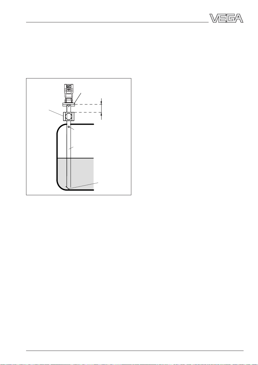
Flange antennas
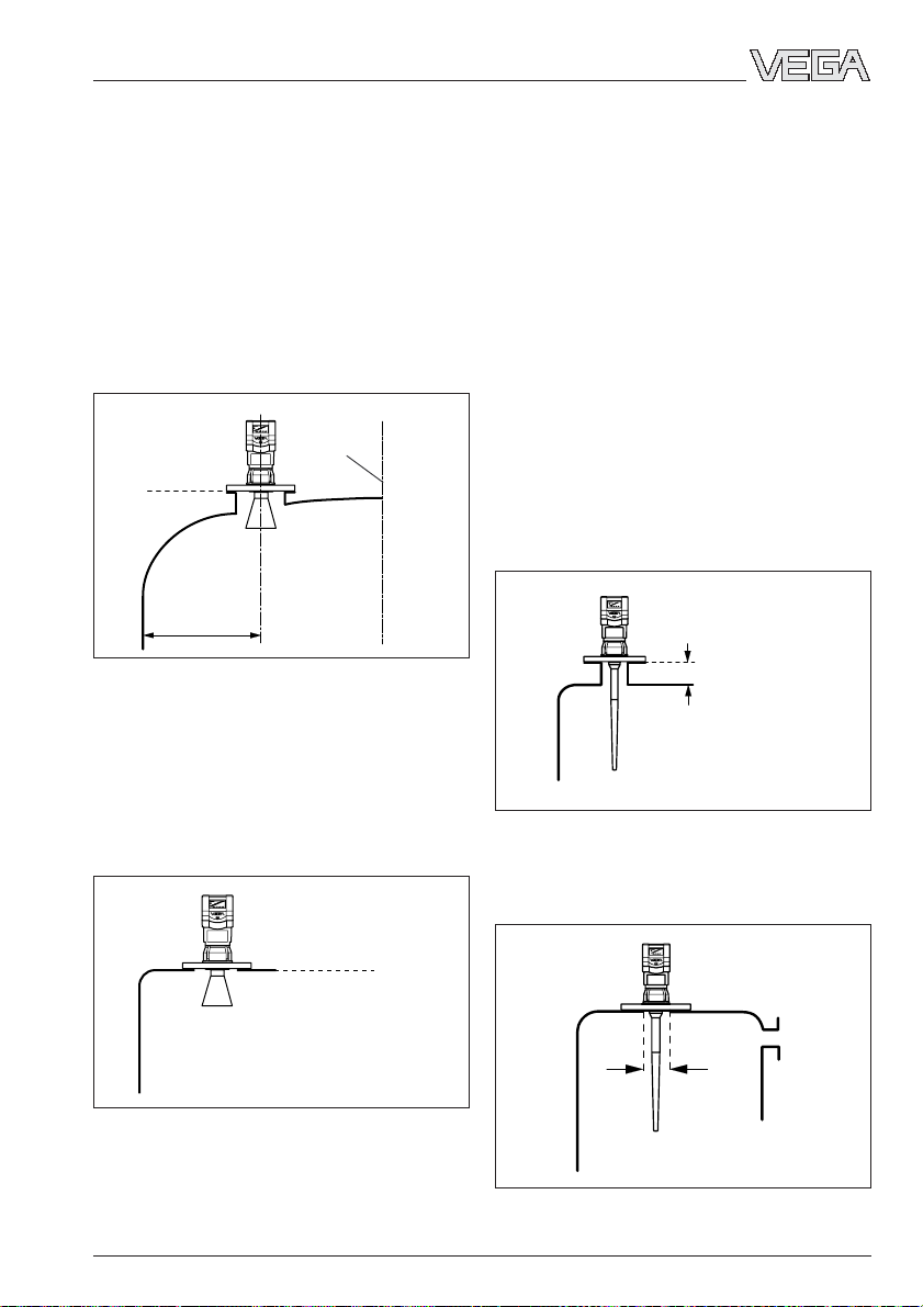
Horn antenna on DIN socket piece
Radar sensors are usually mounted on short
DIN socket pieces. The lower side of the
instrument flange is the reference plane for
the measuring range. The antenna should
always protrude out of the flange pipe.
If the DIN socket piece is longer, make sure
that the horn antenna does not appear in the
socket opening.Better results are achieved
when the antenna protrudes at least 10 mm
out of the socket.
Reference plane
> 10 mm
Mounting on DIN socket piece
In vessels with dished or rounded tops, the
antenna length should at least correspond to
the length of the longer sockets.
Vessel center or
symmetric axis
> 10 mm
Mounting on a dished vessel top
12 VEGAPULS 51K … 54K
21750-EN-031222
Page 13
Mounting and installation
On dished tank ends, please do not mount
the instrument in the centre or close to the
vessel wall, but approx. ½ vessel radius from
the centre or from the vessel wall.
Dished tank ends can act as paraboloidal
reflectors. If the radar sensor is placed in the
focal point of the parabolic tank, the radar
sensor receives amplified false echoes. The
radar sensor should be mounted outside the
focal point. Parabolically amplified echoes are
thereby avoided.
Vessel center or
symmetric axis
Reference plane
½ vessel radius
Mounting on round vessel tops
Horn antenna directly on the vessel top
If the stability of the vessel will allow it (sensor
weight), flat mounting directly on the vessel
top is a good and cost-effective solution. The
top side of the vessel is the reference plane.
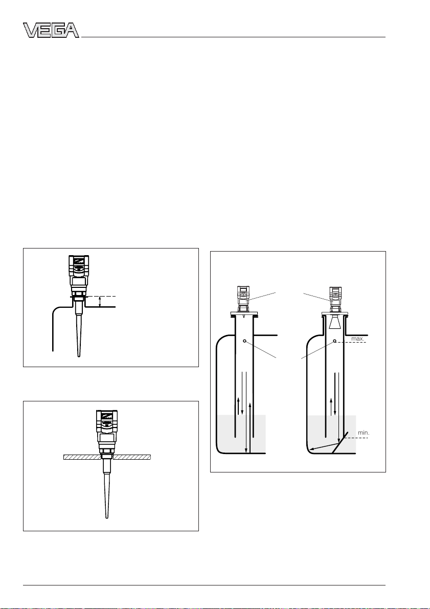
Rod antenna
Rod antenna on DIN socket piece
The PTFE (Teflon) rod antenna is well suited
to chemically aggressive products such as
lyes and acids. Applications in the food
processing industry with aseptic vessel
conditions require nonreactive measuring
systems and very small vessel openings.
The Teflon rod antenna is not only
nonreactive, but can be mounted in very
small vessel openings (50 mm or 1½“ thread
holes).
For measurements of liquids, the Teflon rod
antenna is mounted on a straight DIN socket
piece. The socket however must not be
longer than 150 mm (when using the longer
antenna, not longer than 250 mm). The rod
antenna is available in flange sizes of DN 50,
DN 80 and DN 100.
≤ 50 mm, 100 mm or
250 mm
Rod antenna on DIN socket piece
Rod antenna directly on the vessel opening
Reference plane
Opening
ø 50 mm
Mounting directly on the flat vessel top
Rod antenna directly on the vessel opening
21750-EN-031222
VEGAPULS 51K … 54K 13
Page 14
Mounting and installation
As an alternative to socket mounting, the rod
antenna can also be mounted in round vessel
openings (threaded holes).
Rod antennas are available for the following
vessel openings: 1½“ NPT, DN 50 up to
DN 150. Keep in mind that the PTFE rod
antenna can only be subjected to very small
mechanical loads. If it is subjected to bending forces, deformation or even breakage will
occur.
Rod antenna with thread
When mounting the sensors with 1½“
screwed process connection in a socket
piece, the max. socket length must be observed. The permissible socket length depends on the antenna rod and is 50 mm,
100 mm or 250 mm, see also chapter „8.3
Dimensions“.
Reference plane
≤ 50 mm or 100 mm or
250 mm
3.3 Measurement in standpipe
(surge or bypass tube)
General instructions
Measurement in a standpipe is preferred in
vessels which contain many installations, e.g.
heating tubes, heat exchangers or fast-running stirrers. Measurement is then possible
even when the product surface is very turbulent, and vessel installations can cause no
false echoes.
Due to the concentration of radar signals in
the measuring tube, even products with small
dielectric constants (ε
reliably measured in surge or bypass tubes.
Please observe the following installation directions.
Surge pipe welded
to the tank
= 1.6 up to 3) can be
r
Surge pipe in the
socket piece
Type label
max.
Rod antenna with thread on 1½“ socket
without deflector
Pipe antenna systems in the tank
Vent hole
ø 5 … 10 mm
min.
with deflector
Surge pipes or bypass tubes which are
open at the bottom must extend over the full
measuring range (i.e. down to 0% level), as
Rod antenna with thread on 1½“ thread hole
measurement is only possible within the tube.
The tube inner diameter should be max.
100 mm or correspond to the size of the
antenna horn.
14 VEGAPULS 51K … 54K
21750-EN-031222
Page 15

Mounting and installation
Make sure the required upper vent hole in
the surge pipe is aligned with the sensor
type label.
As an alternative to a surge pipe in the vessel, a pipe antenna system can be installed in
a bypass tube outside the vessel.
With measurement in a surge or bypass
tube, the max. measuring range decreases
by 5 … 20 % (e.g. DN 50: 16 m instead of
20 m and with DN 100 only 19 m instead of
20 m) due to the change of running time of
the radar signal.
Align the sensor so that the type label lies on
the same axis as the tube holes or the tube
connection openings. The polarisation of the
radar signals enables a considerably stabler
measurement with this alignment.
Type label
> 500 mm
100 %
100 %
75 %
0 %
Extended bypass tube on a vessel with turbulent
product movement
Type label
> 500 mm
100 %
0 %
Tube flange system as bypass tube
When mounting a VEGAPULS 52 on a bypass tube (e.g. on a previous floating or
0 %
300 ... 800 mm
displacer unit), the radar sensor should be
placed approx. 500 mm or more from the
Tube flange system as bypass tube
upper tube connection. If the tube has a
rough inner surface, the use of an additional
measuring tube (tube in tube) is recommended, as poor surface quality of the measuring tube hampers radar measurement
through an excessively high „noise level“.
For products with small dielectric values
(< 4), the bypass tube should extend below
the lower tube connection. Products with
small dielectric constants are partly penetrated by the radar signals, which could
allow the tube bottom to deliver a stronger
echo than the product surface (when the
bypass tube is nearly empty). By extending
the lower end of the bypass tube, enough
liquid remains in the tube even when the
vessel i.e. emptied.
21750-EN-031222
VEGAPULS 51K … 54K 15
Page 16
If enough liquid (300 … 800 mm) remains in
the blind lower end of the tube, the portion of
the signal that penetrates the liquid and reflects from the tube bottom is sufficiently
damped - the sensor can then easily distinguish it from the echo of the liquid surface. In
cases where there is not enough liquid at the
bottom of the tube, a deflector situated there
will carry out the same function. It deflects
signals that reach the tube bottom into the
standard connection opening.
Connections to the bypass tube
The connections to the bypass tubes must
be fashioned in such a way that only minimal
reflections are caused by the walls of the
connecting tubes. This is especially important
for the breather connection in the upper part
of the tube. Observe the following points:
• Use small openings for the connection.
• The diameter of the connecting tubes
should not exceed 1/3 of the bypass diameter.
• The tube connections must not protrude
into the bypass.
• Large welding beads in the tubes should
be avoided.
• Additional connections to the bypass tube
must lie in the same plane as the upper
and lower vessel connection (above each
other or displaced by 180°).
Mounting and installation
Welding beads too large
Tube connection protrudes
Additional connection in the bypass tube in one plane
Adhesive products
With adhesive products, a surge pipe with a
larger inner diameter should be used. For
non-adhesive products, the best and most
inexpensive solution is a measurement tube
with a diameter of 50 mm. For slightly adhesive products, use a surge pipe with a nomi-
Optimum connection to the bypass tube
16 VEGAPULS 51K … 54K
nal diameter of 100 mm or 150 mm to prevent
buildup from causing measurement errors.
Measurement of extremely adhesive products in a standpipe is not possible.
21750-EN-031222
Page 17
Mounting and installation
DN 50
ø 50
Pipe antennas with DN 50, DN 80, DN 100 and
DN 150
DN 150
ø 150
Use of guide tubes
In case of very rough inner surfaces in existing bypass tubes (e.g. due to corrosion),
large connection openings as well as bypass
tubes with more than 100 mm inner diameter,
the use of a guide tube inside the existing
bypass tube is recommended. This reduces
the noise level and increases reliability considerably. The flange of the guide tube can
be easily mounted as a sandwich flange
between vessel and sensor flange.
To increase the min. distance, the guide tube
can project out of the surge or bypass tube.
For this purpose, a plain flange can be
welded at the required position on the outside of the extended guide tube. In both
cases, a breather hole must be provided.
Seals on tube connections and tube extensions
Extended guide tube
Microwaves are very sensitive to gaps in
flange connections. If connections are made
without proper care, distinct false echoes as
well as increased signal noise can result.
Guide tube
Observe the following points:
• The seal used should correspond to the
tube inner diameter
• If possible, conductive seal made of materials such as conductive PTFE or graphite
should be used
• There should be as few seal positions as
possible in the guide tube.
Guide tube in existing surge or bypass tube
21750-EN-031222
VEGAPULS 51K … 54K 17
Page 18
Flange connections on bypass tubes
Standpipe measurement of inhomogeneous products
Mounting and installation
If you want to measure inhomogeneous or
stratified products in a surge pipe, it must
have holes, elongated holes or slots. These
openings ensure that the liquid is mixed and
corresponds to the liquid in the vessel.
The more inhomogeneous the measured
product, the closer the openings should be
spaced.
Due to radar signal polarisation, the holes or
slots must be positioned in two rows offset
by 180°. The radar sensor must then be
mounted so that the type label of the sensor
is aligned with the rows of holes.
Type label
ø 5...10
homogeneous
liquids
ø 5...10
slightly inhomogeneous
liquids
VEGAPULS 54: Row of holes in one axis with the type
label
Every wider slot causes a false echo. The
slots should therefore not exceed a width of
10 mm in order to keep the signal noise level
ø 5...10
to a minimum. Round slot ends are better
than rectangular ones.
inhomogeneous liquids
Openings in a surge pipe for mixing of inhomogeneous products
18 VEGAPULS 51K … 54K
21750-EN-031222
Page 19
Mounting and installation
Surge pipe with ball valve
If a ball valve is mounted in the surge pipe,
maintenance and servicing can be carried
out without opening the vessel (e.g. if it contains liquid gas or toxic products).
DN 50
Ball valve
Vent hole
ø50
Tube antenna system with ball valve cutoff in measuring tube
A prerequisite for trouble-free operation is a
ball valve throat that corresponds to the pipe
diameter and provides a flush surface with
the pipe inner wall. The valve must not have
any rough edges or constricted areas in its
channel. The distance to the sensor flange
should be at least 500 mm.
> 500 mm
Deflector
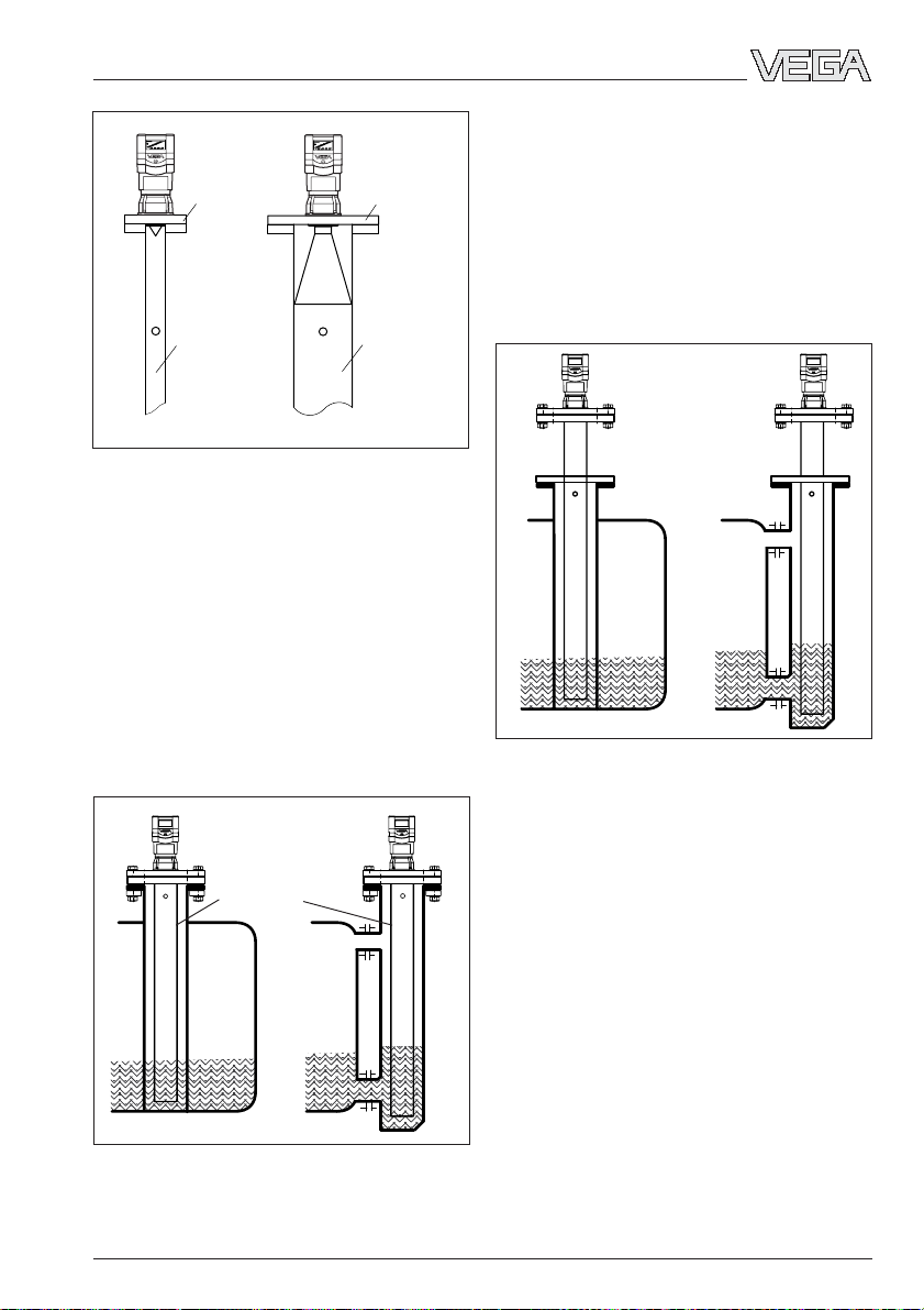
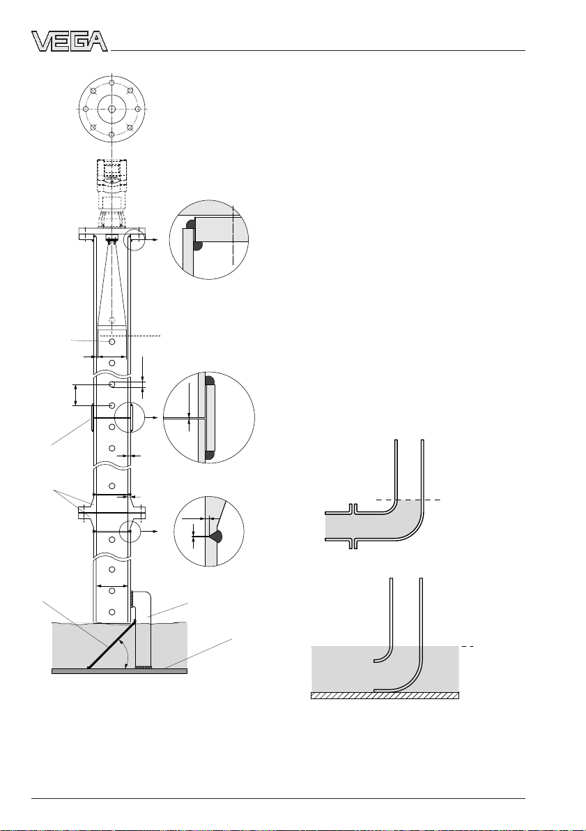
Guidelines for standpipe construction
Radar sensors for measurement on surge or
bypass tubes are used with G 1½ A screwon antenna or in the flange sizes DN 50,
DN 80, DN 100 and DN 150. The radar sensors with a DN 50 flange only forms a functioning measuring system when used in
conjunction with a measuring tube.
The illustration on the left shows the constructional features of a measuring tube (surge or
bypass tube) as exemplified by a radar
sensor with DN 50 flange.
The measuring pipe must be smooth inside
(average roughness Rz ≤ 30). Use stainless
steel tubing (drawn or welded lengthwise) for
construction of the measuring pipe. Extend
the measuring pipe to the required length
with weld-on flanges or with connecting
sleeves. Make sure that no shoulders or
projections are created during welding. Before welding, join pipe and flange with their
inner surfaces flush and exactly fitting.
Avoid welding through the pipe wall. The pipe
must remain smooth inside. Roughness or
welding beads on the inner surfaces must be
carefully removed and burnished, as they
cause false echoes and encourage product
adhesion.
The following illustration shows the constructional features of a measuring tube as exemplified by a radar sensor with DN 100 flange.
If the vessel contains agitated products,
fasten the measuring pipe to the vessel bottom. Provide additional fastenings for longer
measuring pipes.
21750-EN-031222
VEGAPULS 51K … 54K 19
Page 20
Flange
DN 100
VEGAPULS 54
Mounting and installation
In products with lower dielectric values (< 4),
a part of the radar signal penetrates the
medium. If the vessel is nearly empty, echoes
are generated by both the product and the
vessel bottom. The echo from the vessel
bottom can in some cases be stronger than
the echo from the product surface. If a deflector is installed below the open end of the
measuring tube, the radar signals are scattered and prevented from reaching the vessel bottom. This ensures that, in nearly empty
vessels or with products of low dielectric
value, the product delivers a more distinct
echo than the vessel bottom.
Deburr the
holes
150…500
Connecting
sleeve
Welding neck
flanges
Deflector
0 %
Welding of the smooth
welding neck flanges
Due to the deflector, the useful echo (and
thus the measured value) remains clearly
detectable in a nearly empty vessel, and the
0 % level can be reliably measured.
100 %
ø 95
2
Welding of the connecting sleeves
5…10
The standpipe or surge pipe can be
equipped with a quadrant pipe at its end
instead of a deflector. This quadrant pipe
reflects the radar signals that penetrate the
0,0…0,4
medium diffusely to the side and diminishes
strong echoes from the tube end or the vessel bottom.
3,6
Welding of the welding
ø 100,8
~45˚
3,6
neck flanges
1,5…2
0,0…0,4
Meas. pipe fastening
Vessel
bottom
Quadrant pipe on the bypass tube end
0 %
0 %
Quadrant pipe on the standpipe end
20 VEGAPULS 51K … 54K
21750-EN-031222
Page 21
Mounting and installation
3.4 False echoes
The radar sensor must be be installed at a
location where no installations or inflowing
material cross the radar pulses. The following
examples and instructions show the most
frequent measuring problems and how to
avoid them.
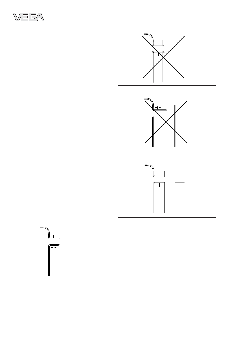
Vessel protrusions
Vessel forms with flat protrusions can make
measurement very difficult due to their strong
false echoes. Baffles mounted above these
flat protrusions scatter the false echoes and
guarantee a reliable measurement.
Correct Incorrect
Vessel protrusions (ledge)
Vessel installations
Vessel installations, such as e.g. ladders,
often cause false echoes. Make sure when
planning your measuring location that the
radar signals have free access to the measured product.
Correct Incorrect
Ladder
Vessel installations
Ladder
Struts
Struts, like other vessel installations, can
cause strong false echoes that overlay the
useful echoes. Small baffles effectively prevent a direct reception of false echoes. These
false echoes are scattered and diffused in
the surrounding space and then filtered out
as "echo noise“ by the measuring electronics.
Intake pipes, i.e. for the mixing of materials with a flat surface directed towards the sensor - should be covered with an angled baffle
Correct Incorrect
that scatters false echoes.
Correct Incorrect
Shields
Struts
Vessel protrusions (intake pipe)
21750-EN-031222
VEGAPULS 51K … 54K 21
Page 22
Mounting and installation
;;
;;
;;
;;
;;
;;
;;
;;
;;
Inflowing material
Do not mount the instrument in or above the
filling stream. Make sure that you detect the
product surface and not the inflowing material.
Correct
Inflowing material
Incorrect
Buildup
If the sensor is mounted too close to the
vessel wall, product buildup and other deposits on the vessel wall cause false echoes.
Position the sensor at a sufficient distance
from the vessel wall. Please also note chapter
"3.1 General installation instructions“.
Correct
Incorrect
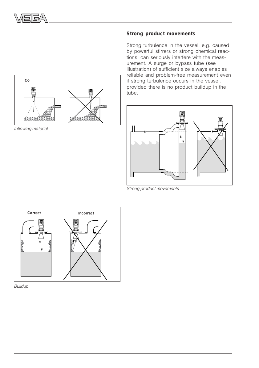
Strong product movements
Strong turbulence in the vessel, e.g. caused
by powerful stirrers or strong chemical reactions, can seriously interfere with the measurement. A surge or bypass tube (see
illustration) of sufficient size always enables
reliable and problem-free measurement even
if strong turbulence occurs in the vessel,
provided there is no product buildup in the
tube.
Correct
Strong product movements
Incorrect
100 %
75 %
0 %
Buildup
22 VEGAPULS 51K … 54K
21750-EN-031222
Page 23
Mounting and installation
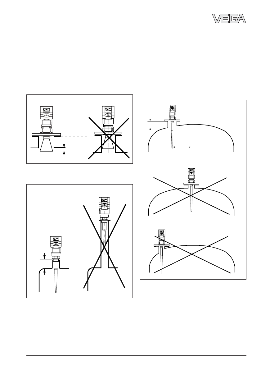
3.5 Common installation mistakes
Socket piece too long
If the sensor is mounted in a socket extension that is too long, strong false echoes are
generated which interfere with the measurement. Make sure that the horn antenna protrudes out of the socket piece.
Correct Unfavourable
Reference plane
≥ 10 mm
Flange antenna: Correct and unfavourable socket
length
Unfavourable
Parabolic effects on dished or rounded
vessel tops
Round or parabolic tank tops act on the radar
signals like a parabolic mirror. If the radar
sensor is placed at the focal point of such a
parabolic tank top, the sensor receives amplified false echoes. The optimum mounting
location is generally in the range of half the
vessel radius from the centre.
Correct
- 100 mm
(250 mm)
~ ½
vessel
radius
Incorrect
Correct
< 100 mm
(250 mm)
Flange antenna: Correct and unfavourable socket
length
Mounting on a vessel with parabolic tank top
Wrong orientation to the product
Weak measuring signals are generated if the
Incorrect
sensor is not directly pointed at the product
surface. Orient the sensor axis perpendicularly to the product surface to achieve optimum measuring results.
21750-EN-031222
VEGAPULS 51K … 54K 23
Page 24
Mounting and installation
Sensor too close to the vessel wall
Strong false echoes can also result if the
radar sensor is mounted too close to the
vessel wall. Buildup, rivets, screws or weld
joints superimpose their echoes onto the
product i.e. useful echo. Please ensure a
sufficient distance from the sensor to the
vessel wall.
Correct Incorrect
Ladder
Direct sensor vertically to the product surface
If there are good reflection conditions (liquid
medium, no vessel installations), we recommend locating the sensor where there is no
vessel wall within the inner emission cone. For
products with less favourable reflection conditions, it is a good idea to also keep the
outer emission cone free of interfering installations. Note chapter "3.1 General installation
instructions“.
Ladder
Standpipe installation mistakes
Pipe antenna without ventilation hole
Pipe antenna systems must be provided with
a ventilation hole on the upper end of the
surge pipe. If this hole is absent, incorrect
measurements will result.
Type label
Incorrect
Incorrect
Correct
Pipe antenna: The surge pipe open to the bottom
must have a ventilation or equalisation hole at the
upper end
Wrong polarisation direction
When measuring in a surge pipe, especially if
there are holes or slots for mixing in the tube,
it is important that the radar sensor is aligned
with the rows of holes.
The two rows of holes (displaced by 180°) of
the measuring tube must be in one plane with
the polarisation direction of the radar signals.
The type label always points in the polarisation direction.
Correct
Foam generation
Thick, dense and creamy foam on the product can cause incorrect measurements. Take
measures to avoid foam, measure in a bypass tube or use another measurement technology, e.g. capacitive electrodes or
hydrostatic pressure transmitters.
VEGAPULS 54 on the surge pipe: The sensor type
plate must be aligned with the rows of holes
24 VEGAPULS 51K … 54K
21750-EN-031222
Page 25

Electrical connection
4 Electrical connection
4.1 Connection and connection cable
Safety information
As a rule, do all connecting work in the complete absence of line voltage. Always switch
off the power supply before you carry out
connecting work on the radar sensors. Protect yourself and the instruments, especially
when using sensors which do not operate
with low voltage.
Qualified personnel
Instruments which are not operated with
protective low voltage or DC voltage must
only be connected by qualified personnel.
Connection cable and screening
A standard two or four-wire cable (sensors
with separate supply) with max. 2.5 mm2 wire
cross-section can be used for connection.
Make sure that the connection cables are
specified for the expected application conditions in your systems. The cable must have
an outer diameter between 5 and 9 mm (1/2
to 1/3 inch), with NPT threads, 3.6 … 8.7 mm
(0.12 to 0.34 inch) and with threaded PG
cable entries, 5 … 10.5 mm. Otherwise, the
seal effect of the cable entry would not be
ensured.
In critical systems, the signal cables are the
source of the problem. The signal cables
often act as antennas that pick up interfering
signals. The 4 … 20 mA signal lines are affected by earth equalisation currents and
especially by current peaks in the ms or µs
range (more so than digital signal lines). This
can be avoided with sophisticated wiring, of
which screening at both ends is a major
feature.
Circumspect system planning, however, will
take into account possible sources of interference from electromagnetic pollution. Due to
the complex interrelationships, it may be
difficult to decide whether measures against
such interference should be taken, and if so,
which ones. And in fact, it is extremely difficult
to describe in theoretical terms the actual
forces at work, since the effects depend
greatly on the frequency of the interfering
magnetic fields: what is very effective for one
frequency can have completely opposite
effects for other frequencies.
Experience has shown that even some relatively simple measures can protect the signal
current circuits against electromagnetic influence. As one of the more costly measures,
screening usually comes at the end of any
catalogue of preventive measures against
interference.
Quite often, the "electromagnetic pollution"
caused by electronic actuators, energy cables and transmitting stations is so considerable that measures against the effects of
electrical and magnetic fields can be necessary. This so-called "electromagnetic pollution" has increased considerably in the last
few years, caused e.g. by fast-cycle power
supply units and mobile phones, especially in
the high-frequency range. VEGAPULS radar
sensors take this into account and are for the
most part insensitive to electromagnetic pollution.
21750-EN-031222
VEGAPULS 51K … 54K 25
Page 26

Electrical connection
Wiring instructions
The signal cables should be wired close to
the ground potential. Wiring in well-grounded
metal cable channels is an effective protection against interference. Obviously, signal
cables should not be wired directly together
with high-energy cables, but should be separated from them, e.g., with sheet metal strips
in the cable channels. Twisted cable (twisted
pair) is especially suitable for signal circuits,
as it compensates coupled voltage vectors.
The distance between the outbound and the
return conductor is just as important as the
distance to ground when it comes to interference signal reception. For that reason, the
distance between the two conductors should
be as small as possible. Twisted pair cable
meets this requirement. These measures are
described by specialists with the expression
"wiring close to the structure". To wire the
signal cable still "closer to the structure", i.e.
even closer to the ground potential, the signal
cable can be provided with screening.
Earthing the screen only on one end is not
always effective, see the following table. The
table gives a simple overview of the effectiveness of the different protective measures
against electromagnetic pollution. In practice,
earthing of both sides is often useful. This
allows the option of earthing only one end
later by simply disconnecting the other earth
contact points of the screen. Why? Actual
interference only appears in the operating
environment. Earthing only one end of the
screen prevents interference, e.g. in the
100 kHz range, better than earthing both
ends, especially if there is insufficient potential equalisation. However, you must make
sure that no ground equalisation currents
flow through the cable screening. Ground
equalisation currents can be avoided by
ground potential equalisation systems. When
earthing on both ends, it is possible to connect the cable screen on one earth side (e.g.
in the switching cabinet) via a YC capacitor1) to
the earth potential. Use a very low-resistance
earth connection (foundation, plate or mains
earth).
Screening magnetic low-frequency high-frequency Ground currents
fields electrical electrical and superimposed
fields fields potential currents
l < ––
λ
7
l > ––
λ
7
none – – – –
one end – ++ – –
both ends + + ++ ++
++ good protection against electromagnetic pollution
+ protection against electromagnetic pollution
– no protection against electromagnetic pollution
Note: λ (Lambda) = –––
c
f
l cable length
c speed of light (300000 km/s)
f interference frequency
λ wave length
Example: Interference frequency approx. 100 kHz
m
1c 1 3 • 10
l < – • – = – • ––––––––– = 4285 m
7 f 7 100 • 10
9
–
s
1
3
–
s
This means that with an interference frequency of 100 kHz up to a cable length of approx.
4000 m, earthing the screen on only one end provides better protection than earthing on both
ends. However, with a cable length of more than 4000 m, earthing on both ends usually produces better results.
1)
max. 10 nF, e.g. voltage resistance 1500 V,
ceramic
26 VEGAPULS 51K … 54K
21750-EN-031222
Page 27

Electrical connection
Ex protection
If an instrument is used in hazardous areas,
the respective regulations, conformity certificates and type approvals for systems in Ex
areas must be noted (e.g. DIN 0165).
Intrinsically safe circuits with more than one
active instrument (instrument delivering electrical energy) are not allowed. Special installation regulations (DIN 0165) must be noted.
Note!
Due to the possibility of potential transfer,
earthing on both ends is prohibited in Ex
applications.
Ground terminals
On VEGAPULS 51 and 52 sensors with 1½“
plastic thread, the ground terminal is galvanically isolated. The sensors have a protective
insulation.
On VEGAPULS 53 and 54 sensors as well as
51 and 52 sensors with metal thread, the
ground terminal is galvanically connected to
the flange or thread.
4.2 Connecting the sensor
After mounting the sensor at the measurement location according to the instructions in
chapter „3 Mounting and installation“, loosen
the closing screw on top of the sensor. The
sensor lid with the optional indicating display
can then be opened. Unscrew the sleeve nut
and slip it over the connection cable (after
removing about 10 cm of cable mantle). The
sleeve nut of the cable entry has a self-locking ratchet that prevents it from opening on
its own.
Now insert the cable through the cable entry
into the sensor. Screw the sleeve nut back
onto the cable entry and clamp the stripped
wires of the cable into the proper terminal
positions.
The terminals hold the wire without a screw.
Press the white opening tabs with a small
screwdriver and insert the copper core of the
connection cable into the terminal opening.
Check the hold of the individual wires in the
terminals by lightly pulling on them.
21750-EN-031222
VEGAPULS 51K … 54K 27
Page 28

Version with plastic housing
Power supply
4 … 20 mA (passive)
+-
1)
To the indicating instrument in the
sensor lid or to the external indicating
instrument VEGADIS 50
Cable entry
M20 x 1.5
Power supply
+-
Electrical connection
4 … 20 mA (active)
+-
To the display in the lid or
the external indicating
instrument
2)
+
-
2
1
4-20mA
Tank 1
m (d)
12.345
Communication
5678
2.23272
Display
ESC
+
-
OK
Two-wire technology in
plastic housing
(loop powered)
1)
4 … 20 mA passive means that the sensor
consumes a level-dependent current of
4 … 20 mA (consumer).
Terminals
(max. 2.5 mm
wire cross-section)
Sockets for connection of
the HART® handheld or
the VEGACONNECT
Pluggable
adjustment
module
MINICOM
2
2)
Communication
4-+3
8765
4-20mA
Display
2.23274
Opening
ESC
+
-
OK
tabs
(+) L1
1
2
N
Tank 1
m (d)
12.345
Four-wire technology in
plastic housing
(separate supply)
4 … 20 mA active means that the sensor provides
a level-dependent current of 4 … 20 mA (current
source).
28 VEGAPULS 51K … 54K
21750-EN-031222
Page 29

ESC
OK
ESC
OK
Electrical connection
Version with aluminium housing
Two-wire technology
(loop powered)
4 … 20 mA passive
+
-
1)
To the indicating instrument in the
sensor lid or to the external indicating
instrument VEGADIS 50
M20 x 1.5
(diameter of the
connection cable
5…9 mm)
Four-wire technology
4 … 20 mA active
Voltage supply
+
-
M20 x 1.5
(diameter of
the connection
cable
6…9 mm)
To the indicating
+
-
instrument in the sensor
lid or to the external
indicating instrument
VEGADIS 50
2)
M20 x 1.5
12 C 567843
12 C 5 6 7 843
(+) (-)
Communication+-4...20mA
-
+
Display
ESC
OK
L1 N
1)
4 … 20 mA passive means that the sensor
consumes a level-dependent current of 4 … 20 mA
(consumer).
Sockets for connection of
VEGACONNECT
(communication
sockets)
2)
4 … 20 mA active means that the sensor provides
a level-dependent current of 4 … 20 mA (current
source).
12 C 567843
12 C 5 6 7 843
(+) (-)
Commu-
L1 N
nication+-4...20mA
Display
ESC
-
+
OK
21750-EN-031222
VEGAPULS 51K … 54K 29
Page 30

Electrical connection
ESC
OK
ESCESC
+
-
OKOK
12 C 5678
(+) (-)
L1 N
Communication
Display
12 C 5 6 7 8
Ver sion with aluminium housing and pressure-tight encapsulated terminal
compartment
Two-wire EEx d terminal compartment
(opening in Ex atmosphere not allowed)
Power supply
-+
Locking of the cover
ser.no ********
R
FM
ATEX
APPROVED
Supply: 20...36V DC/4...20mA HART
R
-+
IS
21
GND
Exd terminal compartment
1
/2“ NPT EEx d
diameter of the
connection cable
3.1…8.7 mm
(0.12…0.34 inch))
Two-wire adjustment module terminal
compartment
(opening in Ex area permitted)
1
/2“ NPT EEx d
diameter of the
connection cable
to the Exd
terminal compartment
3.1…8.7 mm
(0.12…0.34 inch)
Exd safe connection to the
Exd terminal compartment
12 C 5678
12 C 5 6 7 8
(+) (-)
Communication
Display
ESC
-
+
OK
L1 N
Four-wire EEx d terminal compartment Four-wire adjustment module terminal
compartment
(opening in Ex area permitted)
1
Locking of the cover
20...72V DC
12
20...250V AC
+-
Power supply
-+-+
R
R
HART
IS
GND
ser.no ********
4 ... 20 mA
4...20mAsupply
543
+-
Exd terminal
compartment
1
/2“ NPT EEx d
diameter of the
connection cable
to the Exd terminal
compartment
3.1…8.7 mm
(0.12…0.34 inch)
30 VEGAPULS 51K … 54K
/2“ NPT EEx d
diameter of the
connection cable
to the Exd
terminal compartment
3.1…8.7 mm
(0.12…0.34 inch)
Exd safe connection to the
Exd terminal compartment
21750-EN-031222
Page 31

Electrical connection
ESC
OK
-
+
ESC
OK
Tank 1
m (d)
12.345
ESC
OK
4.3 Connecting the external indicating instrument VEGADIS 50
Loosen the four screws of the housing lid on
VEGADIS 50.
The connection procedure can be facilitated
by fixing the housing cover during connection work with one or two screws on the right
of the housing.
Four-wire sensor in aluminium housing
(separate supply)
OUTPUT
(to the sensor)
SENSOR
Power supply
+
-
DISPLAY
(in the lid of the indicating
instrument)
DISPLAY1234 56 78
4 … 20 mA
active
VEGADIS 50
Adjustment
module
Screws
Two-wire sensor in aluminium housing
(loop powered)
4 … 20 mA
passive
+
-
to VEGADIS 50 or to the
display in the sensor lid
12 C 567843
12 C 5 6 7 843
(+) (-)
Communication+-4...20mA
-
+
Display
ESC
OK
12 C 567843
12 C 5 6 7 843
(+) (-)
Communication+-4...20mA
-
+
Display
ESC
OK
L1 N
L1 N
21750-EN-031222
VEGAPULS 51K … 54K 31
M20x1.5
Page 32
Electrical connection
4.4 Configuration of measuring systems
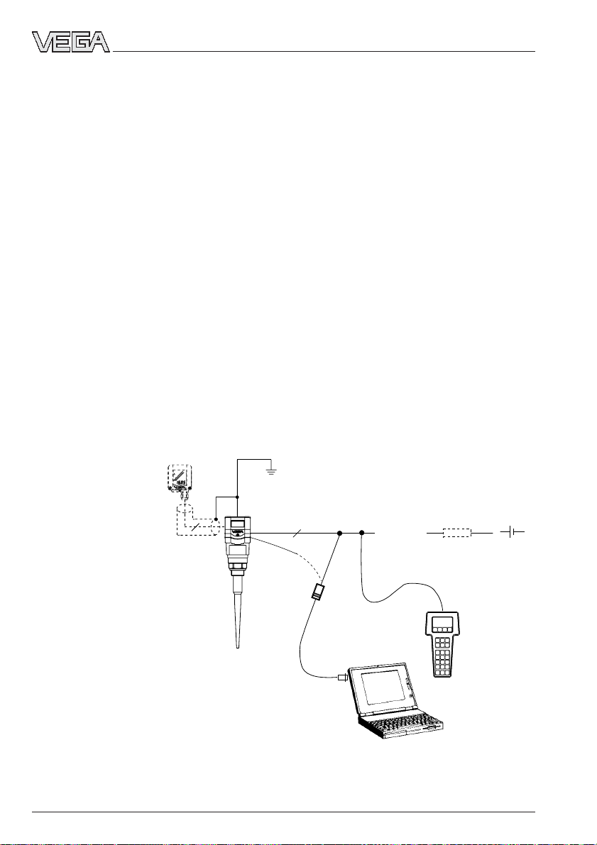
A measuring system consists of a sensor
with 4 … 20 mA signal output and a unit that
evaluates and further processes the levelproportional current signal.
On the following pages, you will see a
number of instrument configurations, designated as "measuring systems“, some of
which are shown with signal processing
units.
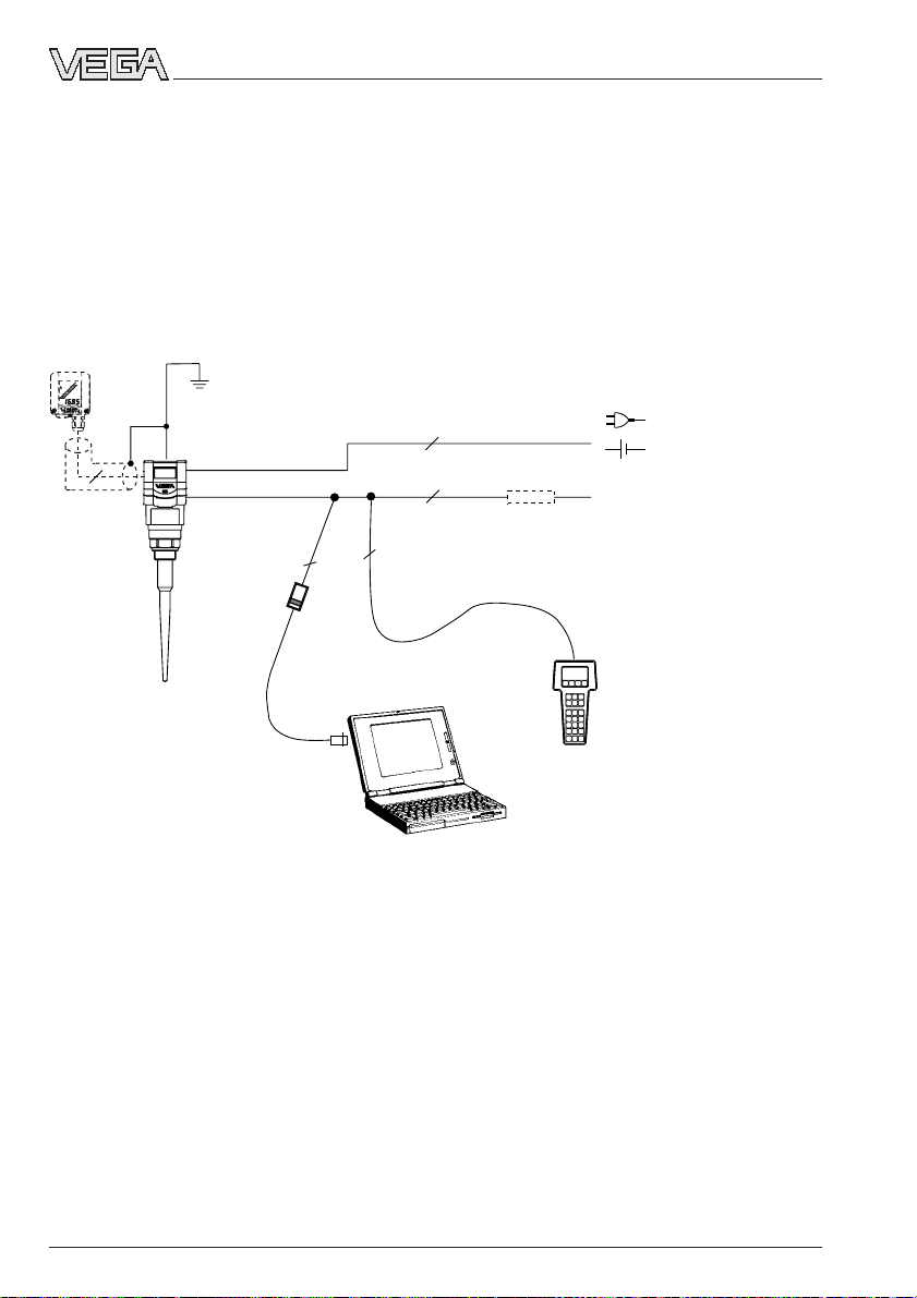
Measuring systems in two-wire technology:
• 4 … 20 mA shown without processing unit
• 4 … 20 mA on active PLC
• 4 … 20 mA in Ex area on active PLC
• 4 … 20 mA in Ex area on passive PLC
• 4 … 20 mA in Ex area on indicating instrument VEGADIS 371 Ex
Measuring systems in four-wire technology:
• 4 … 20 mA shown without signal conditioning instrument
Measuring systems with VEGAPULS 51K … 54K connected to any 4 … 20 mA signal processing unit
• Two-wire technology (loop powered), supply and output signal via one two-wire cable.
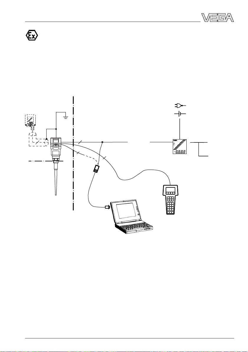
• Output signal 4 … 20 mA (passive).
• Optional external indicating instrument with analogue and digital display (can be mounted
up to 25 m away from the sensor).
• Adjustment with PC, HART® handheld or the adjustment module MINICOM (can be plugged
into the sensor or into the external indicating instrument VEGADIS 50).
VEGADIS 50
4
VEGACONNECT 2
1)
If the resistance of the processing systems
connected to the 4 … 20 mA signal output is less
than 250 Ω, a resistor must be connected to the
connection cable during adjustment to get a loop
resistance of 250 Ω.
The digital adjustment signal would otherwise be
severely damped or short-circuited due to
insufficient resistance of the connected
processing system. Digital communication with the
PC would not be ensured.
32 VEGAPULS 51K … 54K
2
4 … 20 mA
1)
HART® handheld
-
+
21750-EN-031222
Page 33
Electrical connection
Measuring system with VEGAPULS 51K … 54K on active PLC
• Two-wire technology, power supply from active PLC.
• Output signal 4 … 20 mA (passive).
• Measured value display integrated in the sensor.
• Optional external indicating instrument (can be mounted up to 25 m away from the sensor in
Ex area).
• Adjustment with PC, HART® handheld or the adjustment module MINICOM (can be plugged
into the sensor or into the external indication instrument).
VEGADIS 50
1)
4
2
VEGACONNECT 2
4 … 20 mA
2)
passive
2
2
2
PLC (active)
HART® handheld
3)
1)
If the resistance of the processing systems
connected to the 4 … 20 mA signal output is less
than 250 Ω, a resistor must be connected to the
connection cable during adjustment to get a loop
resistance of 250 Ω.
The digital adjustment signal would otherwise be
severely damped or short-circuited due to
2)
4 … 20 mA passive means that the sensor
consumes a level-dependent current of
4 … 20 mA. The sensor reacts electrically like a
varying resistor (consumer) to the PLC.
3)
Active means that the PLC powers the passive
sensor as voltage source.
insufficient resistance of the connected processing
system. Digital communication with the PC would
not be ensured.
21750-EN-031222
VEGAPULS 51K … 54K 33
Page 34
Electrical connection
Measuring system with VEGAPULS 51K … 54K in four-wire technology
• Four-wire technology, power supply and output signal via two separate two-wire cables.
• Output signal 4 … 20 mA active.
• Optional external indicating instrument with analogue and digital indication (can be mounted
up to 25 m away from the sensor).
• Adjustment with PC, HART® handheld or adjustment module MINICOM (can be plugged into
the sensor or into the indicating instrument VEGADIS 50).
• max. resistance on the signal output (load) 500 Ω.
VEGADIS 50
4
2
VEGACONNECT 2
1)
If the resistance of the processing systems
connected to the 4 … 20 mA signal output is less
than 250 Ω, a resistor must be connected to the
connection cable during adjustment to get a loop
resistance of 250 Ω.
The digital adjustment signal would otherwise be
severely damped or short-circuited due to
insufficient resistance of the connected
processing system. Digital communication with the
PC would not be ensured.
2
-
2
1)
≥ 250 Ω
+
4 … 20mA
2)
(active)
2
HART® handheld
2)
4 … 20 mA active means that the sensor delivers
a level-dependent current of 4 … 20 mA (source).
The sensor reacts electrically in the processing
system (e.g. indication) like a current source.
21750-EN-031222
34 VEGAPULS 51K … 54K
Page 35
Electrical connection
Measuring system with VEGAPULS 51K … 54K via separator in Ex areas on
active PLC (Ex ia)
• Two-wire technology (loop powered), power supply via the signal line of the PLC; output
signal 4 … 20 mA (passive).
• Separator transfers the non intrinsically safe PLC circuit to the intrinsically safe circuit, so
that the sensor can be used in Ex zone 1 or Ex zone 0.
• Optional external indicating instrument with analogue and digital display (can be mounted
up to 25 m away from the sensor).
• Adjustment with PC, HART® handheld or adjustment module MINICOM (can be plugged into
the sensor or into the external indicating instrument VEGADIS 50).
VEGADIS 50
4
Zone 0 or
Zone 1
Ex area
EEx ia
Non Ex area
Separator (e.g. Stahl)
(see „7.2 Approvals“)
2
VEGACONNECT 2
1)
4 … 20 mA
passive
2
2)
2
2
PLC (active)
HART® handheld
1)
If the resistance of the processing systems
connected to the 4 … 20 mA signal output is less
than 250 Ω, a resistor must be connected to the
connection cable during adjustment to get a loop
resistance of 250 Ω.
The digital adjustment signal would otherwise be
2)
4 … 20 mA passive means that the sensor or the
PLC consumes a level-dependent current of
4 … 20 mA. The PLC reacts electrically like a
varying resistor (consumer) to the PLC. The PLC
operates actively, i.e. as current or voltage
source.
severely damped or short-circuited due to
insufficient resistance of the connected
processing system. Digital communication with the
PC would not be ensured.
21750-EN-031222
VEGAPULS 51K … 54K 35
Page 36
Electrical connection
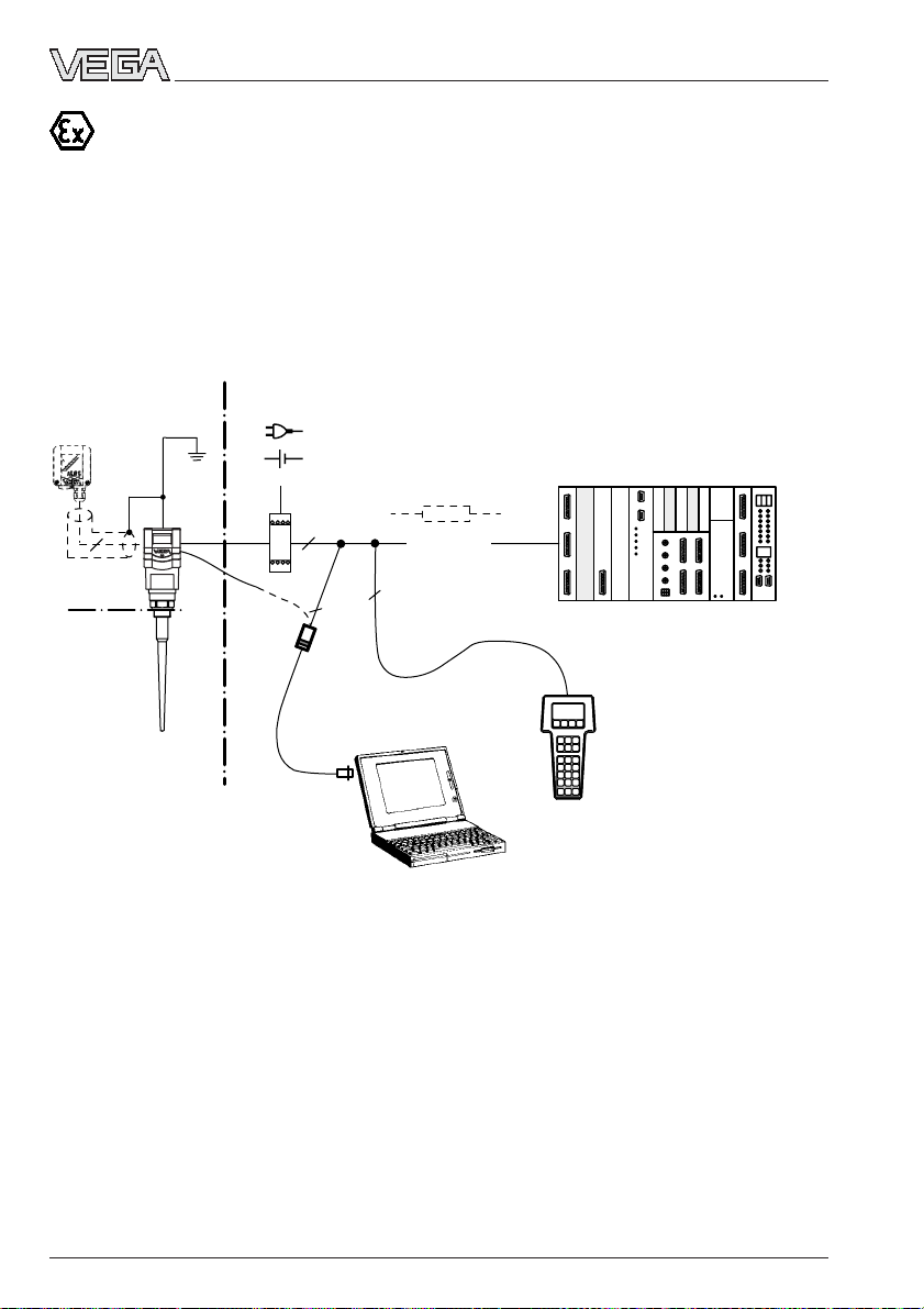
Measuring system with VEGAPULS 51K … 54K via separator (Smart-Transmitter) on passive PLC (Ex ia)
• Two-wire technology (loop powered), intrinsically safe ia supply via the signal cable of the
separator for operation of the sensor in Ex zone 1 or Ex zone 0.
• Output signal sensor 4 … 20 mA passive.
• Output signal separator 4 … 20 mA active
• Optional external indicating instrument with analogue and digital display (can be mounted
up to 25 m away from the sensor).
• Adjustment with PC, HART® handheld or adjustment module MINICOM (can be plugged into
the sensor or into the external indicating instrument VEGADIS 50).
VEGADIS 50
4
Zone 0
or
Zone 1
Ex area
EEx ia
Non Ex area
Separator (e.g. VEGATRENN 149 Ex see
„7.2 Approvals“)
-
+
2
4 … 20 mA
(active)
2
2
VEGACONNECT 2
1)
2)
PLC (passive)
3)
HART® handheld
1)
If the resistance of the processing systems
connected to the 4 … 20 mA signal output is less
than 250 Ω, a resistor must be connected to the
connection cable during adjustment to get a loop
resistance of 250 Ω.
The digital adjustment signal would otherwise be
severely damped or short-circuited due to
insufficient resistance of the connected
processing system. Digital communication with the
2)
4 … 20 mA active means that the separator
delivers a level-dependent current of 4 … 20 mA
The separator reacts electrically to the PLC like a
current source.
3)
4 … 20 mA passive means that the PLC consumes
a level-dependent current of 4 … 20 mA. The PLC
reacts electrically like a varying resistor
(consumer).
PC would not be ensured.
36 VEGAPULS 51K … 54K
21750-EN-031222
Page 37
Electrical connection
Measuring system with VEGAPULS 51K … 54K on VEGADIS 371 Ex indicating instrument with current and relay output (Ex ia)
• Two-wire technology (loop powered), intrinsically safe ia supply via the signal cable of the
VEGADIS 371 Ex indicating instrument for operation of the sensor in Ex zone 1 or Ex
zone 0.
• Optional external indicating instrument with analogue and digital display (can be mounted
up to 25 m away from the sensor).
• Adjustment with PC, HART® handheld or adjustment module MINICOM (can be plugged into
the sensor or into the external indicating instrument VEGADIS 50).
VEGADIS 50
4
Zone 0 or
Zone 1
Ex area
EEx ia
Non Ex area
2
2
2
VEGACONNECT 2
1)
4 ... 20 mA
(passive)
-
+
VEGADIS
371 Ex
(see „7.2 Approvals“)
HART® handheld
Relay
0/4 … 20 mA
(active)
1)
If the resistance of the processing systems
connected to the 4 … 20 mA signal output is less
than 250 Ω, a resistor must be connected to the
connection cable during adjustment to get a loop
resistance of 250 Ω.
The digital adjustment signal would otherwise be
severely damped or short-circuited due to
insufficient resistance of the connected
processing system. Digital communication with the
PC would not be ensured.
21750-EN-031222
VEGAPULS 51K … 54K 37
Page 38
Electrical connection
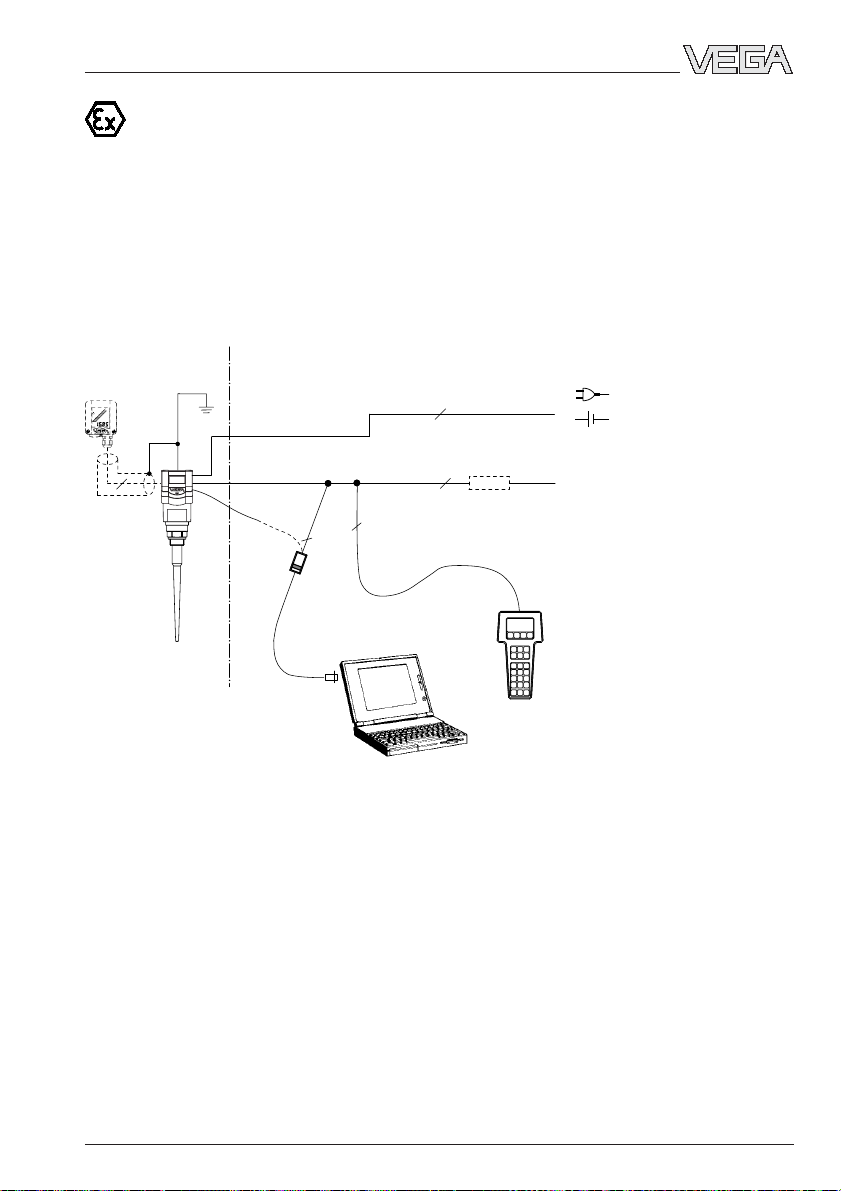
VEGAPULS 51K Ex … 54K Ex (loop powered) with pressure-tight encapsulated connection compartment on active PLC (Ex d)
• Two-wire technology, supply via the cable from active PLC to Exd connection housing for
operation in Ex-Zone 1 (VEGAPULS …Ex) or Ex-Zone 0 (VEGAPULS …Ex0).
• Output signal 4 … 20 mA (passive).
• Measured value display integrated in the sensor.
• Optional external indicating instrument with analogue and digital display (can be mounted
up to 25 m away from the sensor in Ex area).
• Adjustment with PC, HART® handheld or adjustment module MINICOM (can be plugged into
the sensor or into the external indicating instrument VEGADIS 50).
Ex area Non Ex area
VEGADIS 50 Ex
4
1)
If the resistance of the processing systems
2
2
VEGACONNECT 2
2
connected to the 4 … 20 mA signal output is less
than 250 Ω, a resistor must be connected to the
connection cable during adjustment to get a loop
resistance between 250 Ω.
The digital adjustment signal would otherwise be
severely damped or short-circuited due to
insufficient resistance of the connected
processing system. Digital communication with the
PC or the HART® handheld would not be ensured.
4 … 20 mA
2)
passive
2
PLC (active)
®
HART
handheld
2)
4 … 20 mA passive means that the sensor
consumes a level-dependent current of
4 … 20 mA. The sensor reacts electrically like a
varying resistor (consumer) to the PLC.
21750-EN-031222
38 VEGAPULS 51K … 54K
Page 39
Electrical connection
VEGAPULS 51K Ex … 54K Ex with pressure-tight encapsulated connection
compartment in four-wire technology (Ex d)
• Four-wire technology, supply and output signal via two separate two-wire cables for operation in Ex-Zone 1 (VEGAPULS …Ex) or Ex-Zone 0 (VEGAPULS …Ex0).
• Output signal 4 … 20 mA (active).
• Optional external indicating instrument with analogue and digital display (can be mounted
up to 25 m away from the sensor in Ex area).
• Adjustment with PC, HART® handheld or adjustment module MINICOM (can be plugged into
the sensor or into the external indicating instrument VEGADIS 50).
• Load max. 500 Ω.
Ex area
VEGADIS 50 Ex
4
1)
If the resistance of the processing systems
Non Ex area
VEGACONNECT 2
2
2
connected to the 4 … 20 mA signal output is less
than 250 Ω, a resistor must be connected to the
connection cable during adjustment to get a loop
resistance between 250 Ω.
The digital adjustment signal would otherwise be
severely damped or short-circuited due to
insufficient resistance of the connected
processing system. Digital communication with the
PC or the HART® handheld would not be ensured.
2
-
+
2
> 250 Ω
2)
4 … 20 mA active means that the sensor delivers
4 … 20mA
2)
active
HART® handheld
a level-dependent current of 4 … 20 mA (source).
The measuring signal of the sensor reacts
electrically to the processing system (e.g. display)
like a current source.
21750-EN-031222
VEGAPULS 51K … 54K 39
Page 40
5 Set-up
Set-up
5.1 Adjustment media
Radar sensors can be adjusted with the
- PC (adjustment software PACT
- detachable adjustment module
MINICOM
- HART® handheld.
The adjustment must be carried out with only
one adjustment device. If, for example, you
attempt to adjust the parameters with the
MINICOM and the HART® handheld at the
same time, the adjustment will not work.
PC
With the adjustment program PACT
the PC, you can adjust the radar sensors
quickly and conveniently. The PC communicates via the interface adapter
VEGACONNECT 3 with the sensor. During
the process, a digital adjustment signal is
superimposed on the signal and supply
cable. The adjustment can be carried out
directly on the sensor or at any desired location along the signal cable.
Adjustment module MINICOM
With the adjustment module MINICOM, you
adjust directly in the sensor or in the external
indicating instrument VEGADIS 50. With a
dialogue text display and 6 keys, the module
offers the same adjustment functionality as
the adjustment software VVO.
ware
ware
TM
)
TM
on
5.2 Adjustment with PC
When using a sensor in conjunction with a
VEGA signal conditioning instrument, use a
communication resistor according to the
following schedule:
VEGA signal conditioning instr. Rx
VEGAMET 513, 514, 515, 602 50 … 100 Ohm
VEGAMET 614 no additional
VEGADIS 371 resis tor
necessary
VEGAMET 601 200 … 250 Ohm
VEGASEL 643 150 … 200 Ohm
VEGAMET 513 S4, 514 S4
515 S4, VEGALOG EA card 100 … 150 Ohm
HART® handheld
VEGAPULS series 50K radar sensors, like
other HART® protocol compatible instruments,
can be adjusted with the HART® handheld. A
manufacturer-specific DDD (Data-DeviceDescription) is not required. The radar sensors are adjusted with the HART® standard
menus. All main functions are therefore accessible.
Functions that are rarely used, such as, for
example, scaling of the A/D converter for
signal output or adjustment with medium, are
not possible, i.e. disabled, with the HART
®
handheld. These functions must be carried
out with the PC or the MINICOM.
40 VEGAPULS 51K … 54K
21750-EN-031222
Page 41

Set-up
+
-
PLC
Ri ≥ 250 Ω
+
250 Ω
-
PLC
Ri < 250 Ω
Rx
VEGAMET/VEGALOG
21750-EN-031222
VEGAPULS 51K … 54K 41
Page 42

Set-up
5.3 Adjustment with adjustment module MINICOM
You can set up and operate the sensor with
the small, detachable adjustment module
MINICOM just as well as with the PC. The
adjustment module is simply plugged into the
sensor or into the external indicating instrument (optional).
ESC
+
Tank 1
-
m (d)
12.345
OK
2
4 ... 20 mA
ESC
+
Tank 1
-
m (d)
12.345
OK
4
The adjustment module, like the adjustment
program VVO on the PC, provides adjustment options for all sensor versions. There
are some differences with MINICOM, however. For one thing, it is not possible to enter
your own linearisation curve.
Error codes:
E013 No valid measured value
- Sensor in the warm-up phase
- Loss of the useful echo
E017 Adjustment span too small
E036 Sensor program not operating
- Sensor must be reprogrammed
(service)
- Fault signal also appears during
programming
E040 Hardware failure, electronics
defective
Adjustment steps
On the following pages you will find the complete menu schematic of the adjustment module MINICOM.
Set up the sensor in the numbered sequence:
1. Measuring tube adjustments (only for
measurement in a standpipe)
2. Operating range
3. Adjustment
4. Conditioning
5. Meas. conditions
6. False echo storage (only required when
errors occur during operation).
7. Indication of the useful and noise level
8. Outputs
Short explanations to the setup steps 1 … 8
follow.
You carry out all adjustment steps with the 6
1. Measurement in a standpipe
keys of the adjustment module. A small display shows you, apart from the measured
value, a short message on the menu item or
the value entered in a menu item.
Adjustment is only necessary if the sensor is
mounted in a standpipe (surge or bypass
tube). When measuring in a standpipe, do a
sounding of the distance and correct the
The volume of information of the small display
cannot be compared with that of the adjustment program VVO, but you will quickly find
your way and carry out your adjustments
quickly and efficiently with the small
MINICOM.
42 VEGAPULS 51K … 54K
measured value display (which can differ
several percent from the sounded value)
according to the sounding. From then on, the
sensor corrects running time shift of the radar signal and displays the correct value of
the level in the standpipe (measuring tube).
21750-EN-031222
Page 43

Set-up
2. Operating range
Without special adjustment, the operating
range corresponds to the measuring range.
It is generally advantageous to set the operating range slightly larger (approx. 5 %) than
the measuring range.
Example:
Min./max. adjustment: 1.270 … 5.850 m;
adjust operating range to approx.
1.000 … 6.000 m.
3. Adjustment
Max.
Min.
Under the menu item "
the sensor of the measuring range it should
operate in.
You can carry out the adjustment with or
without medium. Generally, you will carry out
the adjustment without medium, as you can
then adjust without a filling/emptying cycle.
100 % (1.270 m) correspond
to 1200 liters
Span (4.58 m)
0 % (5.850 m) corresponds
to 45 liters
Adjustment
“ you inform
Adjustment without medium
(adjustment independent of the level)
Key entry Display indication
Sensor
m(d)
4.700
Para-
OK
OK
OK
OK
+
The distance indication flashes
and you can choose "feet“ and
meter
Adjustment
w.o
medium
Adjustment
in
m(d)
(min. adjustment)
"m“.
OK
+ –
or
Confirm the adjustment with
"OK“.
m(d)
0.0%
at
m (d)
XX.XXX
Adjustment
in
With "+“ and "–“ you adjust the
percentage value for the min.
value (example 0.0 %).
The entered percentage value
OK
is written in the sensor and the
min. distance value corresponding to that percentage
value flashes.
21750-EN-031222
VEGAPULS 51K … 54K 43
Page 44

Set-up
+ –
or
With the "+“ or "–“ key you can
assign a level distance (example 5.85 m) to the previously
adjusted percentage value. If
you do not know the distance,
you have to do a sounding.
The adjusted product dis-
OK
tance is written in the sensor
and the display stops flashing.
You thereby adjusted the lower product distance as well as the percentage filling value
corresponding to the lower product distance.
Note:
For level detection outside the operating range,
the operating range must be corrected accordingly in the menu "
ing range“
Sensor optimisation/Operat-
.
100.0%
at
m (d)
XX.XXX
(max. adjustment)
Now you make the max. adjustment (upper
product distance) (example: 100 % and
1.270 m product distance). First, enter the
percentage value and then the product distance corresponding to that percentage value.
Note:
The difference between the entered values of
the lower product distance and the upper
product distance should be as big as possible, preferably at 0 % and 100 %. If the values are very close together, e.g. lower
product distance at 40 % (3.102 m) and
upper product distance at 45 % (3.331 m),
the measurement will be less accurate. A
characteristic curve is generated from the
two points. Even the smallest deviations
between actual product distance and entered product distance will considerably
influence the slope of the characteristic
curve. If the adjustment points are too close
together, small errors inflate to considerably
larger ones when the 0 % or the 100 % value
is outputted.
Adjustment with medium
with
medium
Max.
Min.
adjust
adjust
at %
at %
XXX.X
XXX.X
Fill the vessel e.g. to 10 % and enter 10 % in
the menu "
Min. adjust
“ with the "+“ and "–“
keys. Then fill the vessel, e.g. to 80 % or
100 % and enter 80 % or 100 % in the menu
"
Max. adjust
“ with the "+“ and "–“ keys.
4. Conditioning
Signal
condit
ioning
Scal
ing
0 %
100 %
Deci-
prop.
corres
corres
ponds
XXXX
mal
point
888.8
Conditioning
ponds
XXXX
Under the menu item "
select product distance at 0 % and at 100 %
filling. Then, you enter the parameter and the
physical unit as well as the decimal point.
Enter in the menu window "
the numerical value of the 0 % filling. In the
example of the adjustment with the PC and
the adjustment software VVO, this would be
45 for 45 liters.
• Confirm with "OK“.
With the "—>“ key you switch to the 100 %
menu. Enter here the numerical value of your
parameter corresponding to a 100 % filling.
In the example 1200 for 1200 liters.
Unit
to
Mass
Kg
“, you
0 % corresponds
“
21750-EN-031222
44 VEGAPULS 51K … 54K
Page 45

Set-up
• Confirm with "OK“.
If necessary, set the decimal point. However,
note that only max. 4 digits can be displayed.
In the menu "
prop. to
“ you choose the physical quantity (mass, volume, distance…) and
in the menu "
Unit
“ the physical unit (kg, l, ft3,
gal, m3 …).
Linearisation:
Adjust
ment
Signal
condit
ioning
Scal
ing
Lin.
curve
Linear
Integra
tion
time
0 s
A linear correlation between the percentage
value of the product distance and percentage value of the filling volume has been preset. With the menu "Lin. curve“ you can
choose between linear, spherical tank and
cylindrical tank. The generation of a customized linearisation curve is only possible with
the PC and the adjustment program VVO.
5. Meas. conditions
(see menu plan no. 5)
Choose "Liquid“ or "Solid“ and the options
corresponding to your application.
7. Useful level, noise level
In the menu
you get important information on the signal
quality of the product echo. The greater the
"S-N“ value, the more reliable the measurement (menu plan MINICOM).
Ampl.: means amplitude of the level echo in
S-N: means Signal-Noise, i.e. the useful
The greater the "S-N“ value (difference between the amplitudes of the useful signal level
and the noise level), the better the measurement:
> 50 dB Measurement excellent
40 … 50 dB Measurement very good
20 … 40 dB Measurement good
10 … 20 dB Measurement satisfactory
5 … 10 dB Measurement sufficient
< 5 dB Measurement poor
Example:
Ampl. = 68 dB
S-N = 53 dB
68 dB – 53 dB = 15 dB
This means that the noise level is only
68 dB – 53 dB = 15 dB.
Ampl.:
XX dB
S-N:
XX
dB
dB (useful level)
level minus the level of the background noise
6. False echo memory
A 15 dB noise level and a 53 dB signal difference yield a high degree of measurement
A false echo storage is always useful when
reliability.
unavoidable false echo sources (e.g. struts)
must be minimised. By creating a false echo
memory, you authorise the sensor electronics
to record the false echoes and save them in
an internal database. The sensor electronics
treats these (false) echoes differently from
the useful echoes and filters them out.
8. Outputs
Under the menu "Outputs“ you determine, for
example, whether the current output should
be inverted, or which unit of measurement
should be shown on the sensor display.
21750-EN-031222
VEGAPULS 51K … 54K 45
Page 46

Menu schematic for the adjustment module MINICOM
Sensor
m(d)
4.700
Parameter
Sensor
optimize
PULS
After switching on, the sensor
54
type and the software version are
K
displayed for a few seconds.
4.00
Configuration
Set-up
Multidrop operation (HART® sensor
address):
• Sensor address zero: The sensor outputs
beside the 4…20 mA signal also a digital
(HART®) level signal.
• Sensor address 1…15: the sensor delivers
only a digital (HART®) level signal. The
sensor current is frozen to 4 mA (power
supply).
Adjust
ment
Meas.
enviro
nment
Operating
range
Begin
0.50
3.
m (d)
2.
End
m (d)
6.00
Meas.
condit
ions
Condit
ion
liquid
Condit
ion
solid
5.
Fast
change
No
Fast
change
No
Sensor
Tag
Verdam
pfer
Agitat
ed sur
face
No
High
dust
level
No
Sensor
addr.
Foaming
prod.
No
Large
angle
repose
No
0
Unit
Low DK
product
No
Multi
ple
echo
No
Signal
condit
ioning
m (d)
Measure in
tube
No
4.
Multi
ple
echo
No
Measur
ing in
tube
Tube
diamet
mm (d)
Correc
tion
Now!
OK?
1.
Correc
tion
factor
2,50 %
50
Correc
tion
Now!
OK?
w.out
medium
Adjust
ment
in
m(d)
0.0 %
at
m (d)
XX.XXX
100.0%
at
m (d)
XX.XXX
with
medium
Minadjust
at %
XXX.X
Maxadjust
at %
XXX.X
Scaling
0 %
corres
ponds
XXXX
Lin.
curve
Linear
100 %
corres
ponds
XXXX
Integr
ation
time
Decimal
point
888.8
0 s
Prop.
Unit
to
Mass
Kg
46 VEGAPULS 51K … 54K
21750-EN-031222
Page 47

Set-up
With these keys you move in
the menu field to the left, right,
top and bottom
ESC
6. 7.
False
echo
memory
Create
new
Meas.
dist.
m (d)
X.XX
Create
new
OK?
Learning!
act.
dist.
m (d)
4.700
Update
Meas.
dist.
m (d)
X.XX
Update
Now!
Learning!
OK?
Ampl.:
XX dB
S-N:
XX
Delete
Delete
Now!
Deleting!
OK?
Act.
dist.
Softw.
date
15.09.
1999
m (d)
4.700
OK
Sensor
addr.
Ampl.:
XX dB
S-N:
XX
0
Act.
current
mA
8.565
dB
Add’l
functions
Serial
no.
1094
0213
max.
range
m (d)
20.000
Language
English
Softw.
vers.
4.00
Sensor
type
PULS54
K
Reset
to de
fault
Reset
Now!
OK?
Reset
ing!
Info
dB
Sensor
Tag
Sensor
Simulation:Simulation:
Simulation:
Simulation:Simulation:
One hour after the last
simulation adjustment, the
sensor returns automatically
to normal operating mode.
8.
Outputs
Curr.
output
Curr.
output
4-20mA
21750-EN-031222
Failure
mode
22mA
Sensor
displ.
Prop.
to
distance
Simulation
Simulation
Now!
Simulation
XXX.X
OK?
Act.
dist.
m
X,XX
High
dust
level
No
%
Fast
change
Yes
Menu items in bolt print
provide sensor and measured
value information and cannot
be modified in this position.
Light grey menu fields are only
displayed if required (dependent
on the adjustments in other
menus).
White menu items can be
modified with the "+“ or "–“ key
and saved with the "OK“ key .
VEGAPULS 51K … 54K 47
Page 48
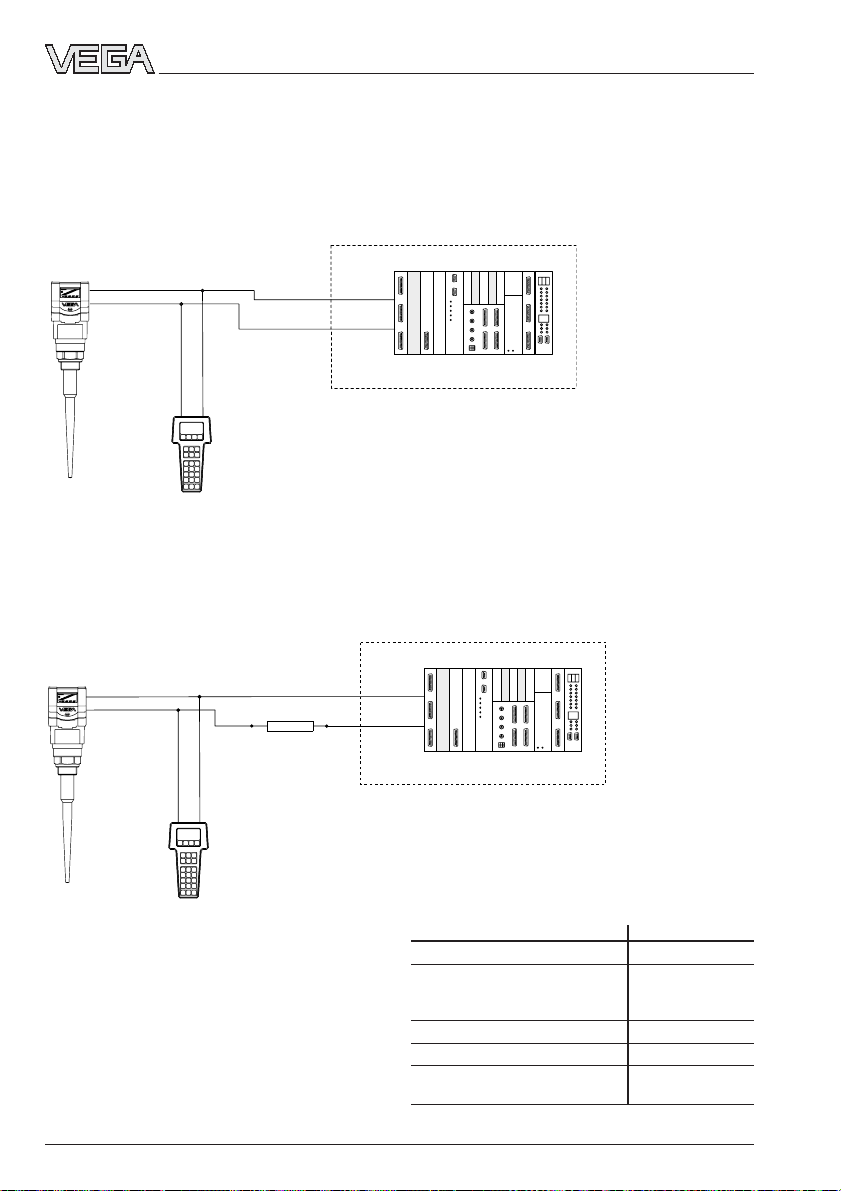
5.4 Adjustment with HART® handheld
With any HART® handheld you can set up the
VEGAPULS series 50K radar sensors like all
other HART® compatible sensors. A special
DDD (Data Device Description) is not necessary.
+
-
Set-up
Just connect the HART® handheld to the
signal cable, after having connected the
sensor to power supply.
Ri > 250 Ω
Note:
If the resistance of the power supply is less
than 250 Ohm, a resistor must be connected
into the signal/connection loop during adjustment.
250 Ω
Connection to a VEGA signal conditioning
instrument
If you operate a HART
®
compatible sensor on
a VEGA signal conditioning instrument, you
have to connect the sensor via a resistor
(see following table) during HART® adjustment. This resistor, together with the internal
resistance of the instruments, provides the
value of 250 Ohm required for the HART
®
instrument. An inherent system load resistance allows a corresponding reduction of Rx.
The digital adjustment and communication
signals would otherwise be short-circuited
due to insufficient resistance of the supply
current source or the processing system,
and as a result, communication with the sensor would not be ensured.
+
-
Ri < 250 Ω
VEGA signal conditioning instr. Rx
VEGAMET 513, 514, 515, 602 50 … 100 Ohm
VEGAMET 614 no additional
VEGADIS 371 resis tor
required
VEGAMET 601 200 … 250 Ohm
VEGASEL 643 150 … 200 Ohm
VEGAMET 513 S4, 514 S4
515 S4, VEGALOG EA card 100 … 150 Ohm
21750-EN-031222
48 VEGAPULS 51K … 54K
Page 49
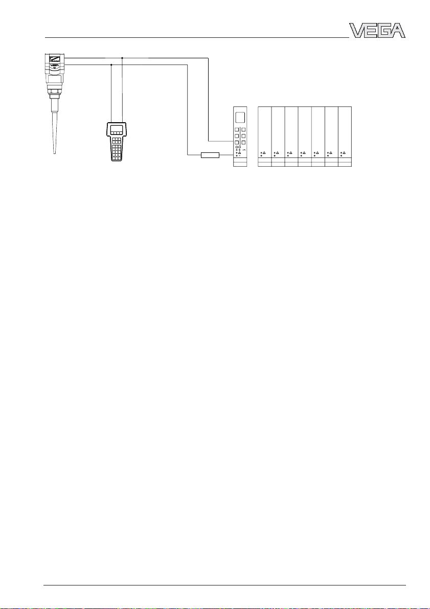
Set-up
VEGALOG VEGAMET
Rx
21750-EN-031222
VEGAPULS 51K … 54K 49
Page 50

6 Diagnostics
6.1 Simulation
To simulate a certain filling level, you can call
up the function “Simulation” in the adjustment
module MINICOM, in the adjustment software
PAC T
You simulate a vessel filling and thereby a
certain sensor current. Please note that connected instruments, such as e.g. a PLC,
react according to their adjustments and will
probably activate alarms or system functions. One hour after the last simulation adjustment, the sensor returns automatically to
standard operating mode.
6.2 Error codes
Display Meani ng Rectifying measure
TM
ware
or in the HART® handheld.
Diagnostics
E013 No valid measured value Message is displayed during warm-up phase
- Sensor in the warm-up
phase
- Loss of the useful echo If the message remains, a false echo storage
must be carried out with the adjustment module
MINICOM in the menu “sensor optimisation” or
better, with the PC and VVO.
If the message still remains, carry out a new
adjustment.
E017 Adjustment span too small Carry out a readjustment.
Make sure that the difference between
min. and max. adjustment is at least 10 mm.
E036 Sensor software does not - Sensor must be programmed with new
run software (service)
- Message appears during a software update.
E040 Hardware failure/Electronics Check all connection cables.
defective Contact our service department.
50 VEGAPULS 51K … 54K
21750-EN-031222
Page 51
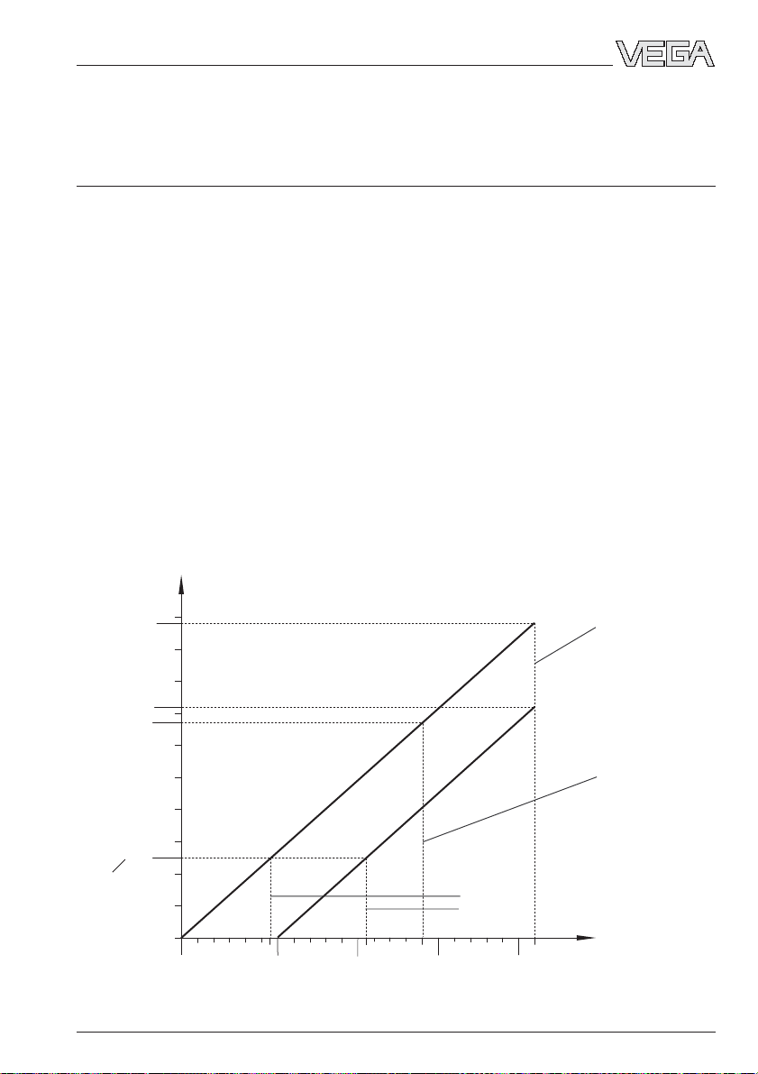
Technical data
7 Technical data
7.1 Technical data
Power supply
Power supply
- four-wire sensor 24 V DC (20 … 72 V DC)
(non-Ex and Ex d ia) 230 V AC (20 … 253 V AC), 50/60 Hz
- two-wire sensor 24 V DC (14 … 36 V DC)
- two-wire Ex ia sensor 24 V DC (14 … 29 V DC)
- two-wire Exd ia sensor 24 V DC (20 … 36 V DC)
Permissible residual ripple of the power
supply with two-wire sensors
- 0 … 125 Hz 1 V
- 125 Hz … 500 Hz 1.0 … 0.01 Vss declining linearly
- 500 Hz … 10 kHz 0.01 V
Power consumption
- four-wire sensor max. 130 mA
- two-wire sensor max. 22.5 mA
Power consumption
- four-wire sensor max. 2.1 W; 7.5 VA
- two-wire sensor 55 … 810 mW
Load
- four-wire sensor max. 500 Ohm
- two-wire sensor see diagram
fuse 0.315 A TR
ss
ss
Ω
max. load non-Ex
19,5
20
max. load Ex d ia
Non-Ex and Ex ia
25,5
25
Exd ia
29
min. voltage limit when using the HART
adjustment resistance:
- non-Ex and Ex ia sensors
- Ex d ia sensors
30 35
36
Adjustment
resistance
(HART® and
VEGACONNECT)
21750-EN-031222
975
720
670
250
1000
900
800
700
600
500
400
300
200
100
max. load Ex ia
0
15
14
VEGAPULS 51K … 54K 51
max. voltage limit
non-Ex and
Ex d ia sensors
max. voltage limit
Ex ia sensors
V
®
Page 52

Technical data
Measuring range
1)
Standard 0 … 20 m
VEGAPULS 54
- DN 50 standpipe 0 … 16 m
- DN 100 standpipe 0 … 19 m
Output signal
Signal output 4 … 20 mA current signal in two-wire or
four-wire technology; the HART® signal is
modulated to the 4 … 20 mA signal
Fault signal current output unchanged, 20.5 mA, 22 mA
(adjustable)
Integration time 0 … 999 seconds (adjustable)
Two-wire technology 4 … 20 mA:
The analogue 4 … 20 mA output signal (measuring signal) is transmitted together with the
power supply via one two-wire cable.
Four-wire technology 4 … 20 mA:
Separate power supply. The analogue 4 … 20 mA output signal (measuring signal) is
transmitted in a cable separate from power supply.
Measured value display (optional)
Liquid crystal indication
- in the sensor scalable output of measured values as graph
and number
- in the external indicating instrument
powered by the sensor scalable output of measured values as graph
and number. The display unit can be mounted
up to 25 m away from the sensor
Adjustment
- PC and adjustment software VEGA Visual Operating
- adjustment module MINICOM
- HART® handheld
1)
Min. distance of the antenna to the medium 5 cm
52 VEGAPULS 51K … 54K
21750-EN-031222
Page 53
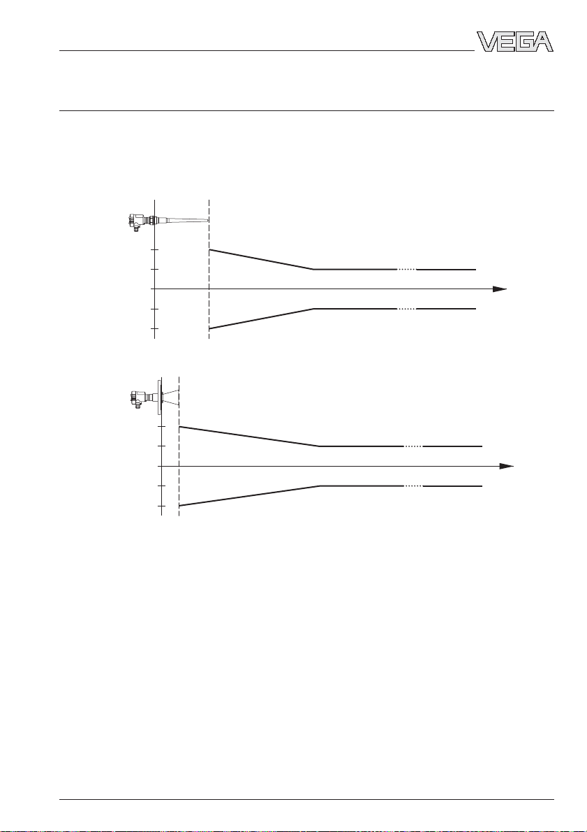
Technical data
Accuracy
1)
(typical values under reference conditions, all statements relate to the nominal measuring
range)
Characteristics linear
Resolution, general max. 1 mm
Resolution of the output signal 1.6 µA or 0.01 %
Accuracy see diagram
Accuracy VEGAPULS 51, 52 and 53
20 mm
10 mm
-10 mm
-20 mm
1,0 m 30 m
Accuracy VEGAPULS 54
20 mm
10 mm
-10 mm
-20 mm
1,0 m 30 m
1)
Similar to DIN 16 086, reference conditions acc. to IEC 770, e.g.
temperature 15 °C … 35 °C; moisture 45 % … 75 %; pressure 860 mbar … 1060 mbar
21750-EN-031222
VEGAPULS 51K … 54K 53
Page 54

Technical data
Characteristics
1)
(typical values under reference conditions, all statements relate to the nominal measuring
range)
Min. span between
full and empty > 10 mm (recommended > 50 mm)
Frequency 5.8 GHz (USA 6.3 GHz)
Intervals
- two-wire sensor (4 … 20 mA) 1 s
- four-wire sensor 0.5 s
Beam angle (at -3 dB)
- VEGAPULS 51 … 53 < 24°
- VEGAPULS 54
DN 80 38° (only suitable for standpipe measurement)
DN 100 30°
DN 150 20°
DN 200 16°
DN 250 14°
Adjustment time (response time)
2)
> 1 s (dependent on the parameter adjustment)
Influence of the process temperature cannot be measured at 0 bar;
at 5 bar 0.004 %/10 °K;
at 40 bar 0.03 %/10 °K
Influence of the process pressure 0.0265 %/bar
Adjustment time
Emitted radar power (average) 0.717 µW
Received average emitted power
2)
3)
> 1 s (dependent on the parameter adjustment)
- distance 1 m 0.4 … 3.2 nW per cm² (0.4 … 3.2 x 10⁻⁹W/cm²)
- distance 5 m 0.02 … 0.13 nW per cm²
Connection cables
Two-wire sensors power supply and signal via one
two-wire cable
Four-wire sensors power supply and signal separated
Electrical connection - spring-loaded terminals (max. 2.5 mm2)
- screwed connection
Cable entry
- ia terminal compartment 1 … 2 x M20 x 1.5 (cable-ø 5 … 9 mm) or
1 … 2 x ½“ NPT EEx d (cable-ø 3.1 … 8.7 mm
or 0.12 … 0.34 inch)
- Exd terminal compartment
(pressure-tight encapsulated) 1 x½“ NPT EEx d (cable-ø 3.1 … 8.7 mm or
0.12 … 0.34 inch)
Ground connection max. 4 mm²
1)
Similar to DIN 16 086, reference conditions acc. to IEC 770, e.g.
temperature 15 °C … 35 °C; moisture 45 % … 75 %; pressure 860 mbar … 1060 mbar
2)
The adjustment time (also actuating time, response time or adjustment period) is the time required by the
sensor to output the correct level (with max. 10% deviation) after a sudden level change.
3)
Average emitted power (electromagnetic energy) received by a body per cm² directly in front of the antenna.
The received emitted power depends on the antenna version and the distance.
54 VEGAPULS 51K … 54K
21750-EN-031222
Page 55

Technical data
Ambient conditions
Vessel pressure
VEGAPULS 51 and 52
- process fitting PVDF -100 … 300 kPa (-1 … 3 bar)
- process fitting StSt -100 … 1600 kPa (-1 … 16 bar)
VEGAPULS 53 -100 … 1600 kPa (-1 … 16 bar)
VEGAPULS 54
- PTFE coupling -100 … 4000 kPa (-1 … 40 bar)
- ceramic coupling -100 … 6400 kPa (-1 … 64 bar)
Ambient temperature on the housing
- 4 … 20 mA two-wire sensor -40 … +80°C
- 4 … 20 mA four-wire sensor -40 … +80°C
- 4 … 20 mA four-wire sensor Ex d ia -40 … +60°C
Process temperature (flange temperature)
VEGAPULS 51
- process fitting PVDF -20 … +80°C
- process fitting StSt -40 … +120°C
VEGAPULS 52
- process fitting PVDF -20 … +120°C (short-term 130°C)
- process fitting StSt -40 … +150°C
VEGAPULS 53 -40 … +150°C
VEGAPULS 54
- PTFE coupling (standard) -25 … +150°C
- PTFE coupling (option) -15°C/-30°C/-40 … +150°C
- ceramic coupling -60 … +250°C
Storage and transport temperature -60 … +80°C
Protection IP 66 and IP 67
Protection class
- two-wire sensor II
- four-wire sensor I
Overvoltage category III
Ex-technical data
Comprehensive data in the safety instructions manual (yellow binder)
WHG approvals
All VEGAPULS 51 … 54 radar sensors are approved as part of an overfill protection system for stationary vessels storing water-endangering liquids.
21750-EN-031222
VEGAPULS 51K … 54K 55
Page 56

Materials
Housing PBT (Valox) or
Aluminium die casting (GD-AlSi 10 Mg)
Connection compartment
(with EExd version) Aluminium mould casting (GK-AlSi 7 Mg)
Process fitting
- VEGAPULS 51 (thread) PVDF or StSt (1.4435)
- VEGAPULS 52 (thread) PVDF or StSt (1.4571)
- VEGAPULS 53, 54 (flange) 1.4571 or Hastelloy C4
Antenna (wetted materials)
- VEGAPULS 51 (rod antenna) PVDF/PP or StSt/PPS
- VEGAPULS 52 (rod antenna) PTFE or PVDF
- VEGAPULS 53 (rod antenna) PTFE
- VEGAPULS 54
horn antenna 1.4571, Hastelloy C22 or PTFE
pipe antenna PTFE/1.4571 or PTFE/Hastelloy
Antenna seal of the
coupling cone
- standard Viton
- option Kalrez, NBR, EPDM,
FEP-Viton coated, graphite
Flange coating (type 53) PTFE
Weights
All weights are valid for sensors with PBT housing and in non-Ex version.
For sensors with Aluminium housing the weights increase by 0.8 kg.
For sensors in Ex version the weights increase in addition by:
- 0.3 kg with Ex ia sensors
- 1.4 kg with Ex d sensors.
VEGAPULS 51
- screwed connection G 1½ A, 1½“ NPT
socket length up to 50 mm 1.3 kg (screwed connection PVDF)
socket length up to 100 mm 2.0 kg (screwed connection 1.4435)
socket length up to 250 mm 2.37 kg (screwed connection 1.4435)
- Tri-Clamp
(DIN 32 676, ISO 2852, DN 50) 1.62 kg (socket length max. 50 mm)
- R-connection (DIN 11 851, DN 50) 2.1 kg (socket length max. 50 mm)
VEGAPULS 52
- screwed connection G 1½ A, 1½“ NPT
(PVDF)
socket length up to 50 mm 1.5 kg
socket length up to 100 mm 1.87 kg
socket length up to 250 mm 2.26 kg
- screwed connection G 1½ A, 1½“ NPT
(14571)
socket length up to 50 mm 2.5 kg
socket length up to 100 mm 2.8 kg
socket length up to 250 mm 3.15 kg
- Tri-Clamp
(DIN 32 676, ISO 2852, DN 50) 1.62 kg (socket length max. 50 mm)
- R-connection (DIN 11 851, DN 50) 2.1 kg (socket length max. 50 mm)
Technical data
21750-EN-031222
56 VEGAPULS 51K … 54K
Page 57

Technical data
VEGAPULS 53
- DN 50 PN 40
standpipe version 4.95 kg
socket length up to 100 mm 5.15 kg
socket length up to 250 mm 5.82 kg
- DN 80 PN 40 + 2.0 kg
- DN 100 PN 16 + 3.1 kg
- DN 150 PN 16 + 7.7 kg
- DN 200 PN 16 + 14.1 kg
- DN 250 PN 16 + 22.3 kg
- ANSI 2“
standpipe version 4.15 kg
socket length up to 100 mm 4.35 kg
socket length up to 250 mm 5.1 kg
- ANSI 3§ + 2.1 kg
- ANSI 4“ + 5.0 kg
- ANSI 6“ + 9.1 kg
- ANSI 8“ + 20.4 kg
- ANSI 10“ + 28.1 kg
VEGAPULS 54
- DN 50 PN 40 4.8 kg
- DN 80 PN 40 7.6 kg
- DN 100 PN 16 8.4 kg
- DN 150 PN 16 13.1 kg
- DN 200 PN 16 23.1 kg
- DN 250 PN 16 28.5 kg
- ANSI 2“ 4.8 kg
- ANSI 3§ 6.6 kg
- ANSI 4“ 10.2 kg
- ANSI 6“ 14.3 kg
- ANSI 8“ 29.3 kg
- ANSI 10“ 34.3 kg
CE conformity
VEGAPULS series 50 radar sensors meet the protective regulations of EMC (89/336/EWG)
and NSR (73/23/EWG) and R & TTE directive (1999/5/EC).
Conformity was judged acc. to the following standards:
EN 300 683-1: 1997
EN 300 440-1: 1995
I-ETS 300-440
Expert opinion No. 0043052-01/SEE, Notified Body No. 0499
EN 61 326: 1997/A1: 1998 (EMC Emission/Susceptibility)
EN 61 010 - 1: 1993 (NSR)
EN 50 020: 1994 (ATEX)
EN 50 018: 1994
EN 50 014: 1997
21750-EN-031222
VEGAPULS 51K … 54K 57
Page 58

Technical data
7.2 Approvals
When radar sensors are used in Ex areas or
on ships, the instruments must be suitable
and approved for the explosion zones and
applications.
The suitability is checked by the approval
authorities and is certified in approval documents.
Please note the attached approval documents when using a sensor in Ex area.
Test and approval authorities
VEGAPULS radar sensors are tested and
approved by the following monitoring, test
and approval authorities:
- PTB
(Physikalisch Technische Bundesanstalt Physical Technical Approval Authority)
- FM
(Factory Mutual Research)
- ABS
(American Bureau of Shipping)
- LRS
(Lloyds Register of Shipping)
- GL
(German Lloyd)
- CSA
(Canadian Standards Association)
Intrinsically safe in Ex environment
Series 50 sensors in EEx ia (intrinsically safe)
version require for use in Ex areas special
separators or safety barriers. The separators
or safety barriers provide intrinsically safe
(ia) circuits. Below, a selection of instruments
with which series 40 sensors work reliably.
Separator and signal conditioning instrument:
- VEGADIS 371 Ex
- A puissance 3 PROFSI 37-24070A
- VEGAMET 614 Ex
- Apparatebau Hundsbach
AH MS 271-B41EEC 010
Separator, safety barrier:
- Stahl 9001/01/280/110/10
- Stahl 9001/51/280/110/14
- MTL 787 S+
- CEAG CS 3/420-106
Separator:
- VEGATRENN 149 Ex…
- Stahl 9303/15/22/11
- CEAG GHG 124 3111 C1206
Pressure-tight encapsulated in Ex area
Series 50 sensors in EEx d ia (pressure-tight
encapsulated) version can be used in Ex
areas without special safety barriers due to
their pressure-tight encapsulated terminal
compartment (provided the appropriate
installation regulations are observed).
SIL conformity and IEC 61508 /
IEC 61511
VEGAPULS radar sensors meet the requirements on functional safety acc. to IEC 61508 /
IEC 61511. For further information see Supplement under „Safety Manual“.
58 VEGAPULS 51K … 54K
21750-EN-031222
Page 59

Technical data
7.3 Dimensions
External indicating instrument VEGADIS 50
85
38
5
ø
48
10
Pg 13,5
Mounting on carrier rail 35 x 7.5 acc. to EN 50 022 or flat
screwed
118
108
135
82
Note:
The diameter of the connection cable should
be min. 5 mm and max. 9 mm.
Otherwise the seal effect of the cable entry
85
would not be ensured.
Flange dimensions acc. to ANSI (RF)
d
2
b
f
d
1
k
D
Size Flange Seal ledge Holes
Db k d1No. d
2" 150 psi 152.4 20.7 120.7 91.9 4 19.1
3" 150 psi 190.5 25.5 152.4 127.0 4 19.1
4" 150 psi 228.6 25.5 190.5 157.2 8 19.1
6" 150 psi 279.4 27.0 241.3 215.9 8 22.4
D=outer flange diameter
b = flange thickness
k = diameter of hole circle
d1= seal ledge diameter
f = seal ledge thickness
1
/16" = approx. 1.6 mm
d2= diameter of holes
Adjustment module MINICOM
ESC
+
-
Tank 1
m (d)
12.345
67,5
74
32,5
OK
Adjustment module for insertion into sensors
or into the external indicating instrument
VEGADIS 50
2
21750-EN-031222
VEGAPULS 51K … 54K 59
Page 60

VEGAPULS 51, 52
Technical data
PBT
Aluminium
Aluminium with
Exd terminal
201
165
215
185
0
10˚
322
182
91
M20x1,5
101
20
2
SW 60
7
3
5
0
2
PBT: 577 (417)
21
ø60
ø85
Al: 600 (440)
24
ø25
190
330
PBT: 607 (757)
360 (510)
116
Al: 630 (780)
395 (545)
25
M20x1,5
ø36
ø35
compartment
0
7
3
PBT: 642 (792)
Al: 665 (815)
215
185
5
0
2
116
25
½" NPT
G 11/2 A or
11/2“ NPT
G 11/2 A or
11/2“ NPT
G 11/2 A or
11/2“ NPT
Rod length max. socket length
VEGAPULS 51 330 50 m m
VEGAPULS 51 190 for standpipe __
VEGAPULS 51 360 (option 510) 100 mm (option 250 mm)
VEGAPULS 52 330 50 m m
VEGAPULS 52 190 for standpipe __
VEGAPULS 52 395 (option 545) 100 mm (option 250 mm)
VEGAPULS 53 395 (option 545) 100 mm (option 250 mm)
60 VEGAPULS 51K … 54K
21750-EN-031222
Page 61

Technical data
VEGAPULS 53
PBT
Aluminium
Aluminium with
Exd terminal
25
22
2
395 (545)
compartment
0
7
3
5
0
2
ø36
ø35
ø22
45˚
185
215
PBT: 654 (804)
Al: 702 (852)
116
25
½" NPT
201
165
215
185
0
PBT
7
3
5
0
2
3
5
PBT: 652 (802)
Al: 700 (850)
2
ø36
20
ø35
395 (545)
8
1
ø
45˚
10˚
322
182
91
2
ø36
18
ø35
395 (545)
ø18
M20x1,5
101
PBT: 650 (800)
Al: 698 (848)
2
20
395 (545)
116
M20x1,5
3
Al
7
PBT: 652 (802)
Al: 700 (850)
ø36
ø35
ø18
45˚
ø104
ø125
ø165
DN 50 PN 40 (C)
ø138
ø160
ø200
DN 80 PN 40 (C)
ø158
ø180
ø220
DN 100 PN 16 (C)
ø216
ø240
ø285
DN 150 PN 16 (C)
21750-EN-031222
VEGAPULS 51K … 54K 61
Page 62

VEGAPULS 54
Technical data
ø76
Aluminium
185
0
7
3
5
0
2
6
7
1
20
PBT: 330 (250˚C: 456)
Al: 373 (250˚C: 495)
75
Aluminium with Exd
terminal compartment
215
200 °C
ø96
116
5
9
1
20
PBT: 375 (250˚C: 498)
120
25
M20x1,5
250 °C
Al: 418 (250˚C: 540)
ø146
0
7
3
22
205
5
0
2
PBT: 462 (250˚C: 585)
Al: 505 (250˚C: 627)
215
185
116
25
½" NPT
PBT: 617
Al: 690
26
380
PBT
201
165
10˚
322
182
91
PBT
M20x1,5
3
5
18
101
23
PBT: 276 (250˚C: 399)
Al: 319 (250˚C: 441)
3
7
Al
ø241
6
2
ø
4
5
˚
ø355
ø405
8
1
8
1
ø
ø125
ø165
ø18
ø160
ø200
45˚
ø
ø180
ø220
45˚
DN 50 PN 40 (C) DN 80 PN 40 (C) DN 100 PN 16 (C)
ø22
ø240
ø285
DN 150 PN 16 (C)
DN 250 PN 16 (C)
62 VEGAPULS 51K … 54K
21750-EN-031222
Page 63

Supplement
Supplement
Safety Manual
Functional safety acc. to IEC 61508 / IEC 61511
®
VEGAPULS series 50 radar sensors; 4 … 20 mA/HART
1 General
1.1 Validity
This safety manual applies to VEGAPULS series 50 radar sensors in two-wire version
4 … 20 mA/HART®, called “measuring system” in the following.
1.2 Area of application
The measuring system can be used for the following functions which meet the specific requirements of the safety technology:
- overfill protection
- dry run protection
- detection of an individual level
The functions can be also used simultaneously.
The functions can be used in the mode of operation with low demand mode as well as in the
mode of operation with high demand or continuous mode.
compact sensor
The measuring system is qualified in all modes to meet the requirement degree SIL2 acc. to
IEC 61508-2 / IEC 61511-1.
The measuring system is designed for 15 years of use in safety-related applications.
In safety-related systems with an architecture 1oo2D and the requirement SIL3, the measuring
system must be combined with a second, different measuring system (diversely redundant).
The safety-related characteristics must be calculated separately.
1.3 Relevant standards
• IEC 61508 part 1, 2, 4
Functional safety of electrical/electronic/programmable electronic systems
• IEC 61511-1
Functional safety – safety instrumented systems for the process industry sector –
Part 1: Framework, definitions, system, hardware and software requirements
21750-EN-031222
VEGAPULS 51K … 54K 63
Page 64
Supplement
1.4 Determination of safety-related characteristics
The failure limit values for a safety function, depending on the SIL class.
Safety integritySafety integrity
Safety integrity Low demand mode High demand or continuous
Safety integritySafety integrity
level mode
SIL PFD
4 >10-5 up to <10
3 >10-4 up to <10
2 >10-3 up to <10
1 >10-2 up to <10
avg
-4
-3
-2
-1
(from IEC 61508, part 1/7.6.2)
Safety integrity of the hardware:
Limitations due to the architecture for safety-related subsystems of type B
PFH
>10-9 up to <10
>10-8 up to <10
>10-7 up to <10
>10-6 up to <10
-8
-7
-6
-5
Safe failure fraction SFF Hardware fault tolerance HFT
0 1 (0)
1)
2
< 60 % not allowed SIL 1 SIL 2
60 % up to < 90 % SIL 1 SIL 2 SIL 3
90 % up to < 99 % SIL 2 SIL 3 (SIL 4)
> 99 % SIL 3 (SIL 4) (SIL 4)
(from IEC 61508, part 2/7.4.3)
1)
Acc. to IEC 61511-1, paragraph 11.4.4 the fault tolerance specified acc. to the above chart can be reduced
by one for all subsystems if the following conditions are met:
- instrument has proven during operation
- only process-relevant parameters can be modified on the instrument (e.g. measuring range, …)
- the adjustment of this process-relevant parameters is protected (e.g. password, …)
- the safety function needs less than SIL 4
21750-EN-031222
64 VEGAPULS 51K … 54K
Page 65

Supplement
2 Planning
2.1 Low demand mode
If the demand rate is only once a year, then the measuring system can be used as safetyrelevant subsystem in „low demand mode“ (see IEC 61508-4, 3.5.12).
Corresponding characteristics : PFD
It is dependent on the test interval T
(average probability of dangerous failure on demand).
avg
between the function tests of the protective function.
Proof
2.2 High demand or continuous mode
If the demand rate is more than once a year, the measuring system must be used as safetyrelevant subsystem in „high demand or continuous mode“ (see IEC 61508-4, 3.5.12).
The fault reaction time of the measuring system must be set to less than or at the most, equal
to the fault tolerance time of the total system. The smallest fault reaction time of the measuring
system is 60 sec.
Corresponding characteristics: PFH (probability of a dangerous failure per hour)
2.3 General
The safe condition of the measuring system in case of failure is defined for both modes of
operation at an output current > 21 mA. An output current < 3.6 mA and > 21 mA must be
configured as alarm in the processing unit.
Definition of a dangerous undetected failure:
- the instrument does not react to the demand of the process
- the output current deviates by more than 2 % from the actual value.
Otherwise the tolerance data in the operating instructions manual are applicable. Make sure
that the measuring system is used as it was intended for the application (see operating instructions manual). The application-specific limits must be complied with and the specifications
must not be exceeded (see operating instructions manual). Use only in products against
which the materials of the antenna system are sufficiently chemically resistant.
21750-EN-031222
VEGAPULS 51K … 54K 65
Page 66

Supplement
3 Set-up
3.1 Mounting and installation
The prevailing plant conditions influence the safety of the measuring system. Therefore note
the mounting and installation instructions of the appropriate operating instructions manual.
3.2 Adjustment instructions and parameter adjustment
Adjustment instructions
The activation of the measuring system as safety-relevant subsystem is only possible via PC
adjustment programs. Not all safety-relevant parameters can be adjusted with the adjustment
module MINICOM. The set parameters must be checked and protected against unauthorised
access (password, screwed housing cover, …).
General instructions, see operating instructions manual
Parameter adjustment
The following software versions are required:
- Sensor software: from 4.50.00
- DTM-Collection: from 10/2003
With the adjustment program PACT
the Device Type Manager (DTM).
Note
If a reset is triggered on the sensor after the SIL parameter adjustment or if the failure mode =
22 mA is changed, the sensor will loose its SIL qualification.
ware
™, the SIL parameter adjustment must be activated in
3.3 Configuration of the processing unit
If the measuring system delivers output currents > 21 mA or < 3.6 mA, it must be assumed
that a failure has occurred.
The processing unit must therefore interpret such current values as a failure and trigger a
suitable fault signal.
21750-EN-031222
66 VEGAPULS 51K … 54K
Page 67

Supplement
4 Reaction during operation and in case of failure
In case of modifications during operation, you have to take note of the safety functions. It must
be ensured that the safety-relevant parameter adjustments remain activated.
Occurring fault signals are described in the appropriate operating instructions manual.
In case of detected failures or fault signals, the entire measuring system must be switched out
of service and the process held in a safe condition by means of other measures.
5 Recurring function test
The recurring function test serves to reveal potential dangerous errors that are otherwise not
discernible.
The function of the measuring system must be checked at adequate intervals. The operator is
responsible for choosing the type of test and the intervals in the stated time frame.
The time intervals depend upon the applied PFD
paragraph „Safety-related characteristics“.
value acc. to the chart and diagram in the
avg
The test must be carried out in a way that verifies the flawless operation of the safety functions
in conjunction with all system components. This is ensured by a controlled reaching of the
response height during a filling.
If filling up to the response height is not possible, then a response of the measuring system
must be triggered by a suitable simulation of the level or the physical measuring effect. If the
proper functioning of the measuring system is otherwise discernible (exclusion of functionrestraining errors), it is also possible to carry out the test by simulating the appropriate output
signal.
If the function test proves negative, the entire measuring system must be switched out of
service and the process held in a safe condition by means of other measures.
21750-EN-031222
VEGAPULS 51K … 54K 67
Page 68
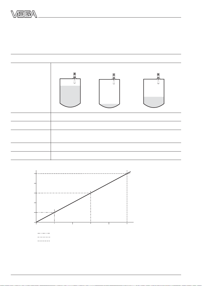
2
2
2
2
2
2
Supplement
6 Safety-related characteristics
The failure rate of the electronics and the antenna system was determined by an FMEDA (Failure Mode, Effects and Diagnostics Analysis) acc. to IEC 61508. The number values are based
on an output current tolerance of max. 2 %.
Architecture 1oo1D SIL 2
VEGAPULS 51 Overfill protection Dry run protection Individual level
VEGAPULS 52
VEGAPULS 53
VEGAPULS 54
VEGAPULS 56
HFT 0
SFF > 86%
avg
1)
3)
PFD
PFH [1/h]
Max
< 0.12 •10
< 0.60 •10
< 0.28 •10
Min
-2
-2
-6
with T
with T
= 1 year
Proof
= 5 years
Proof
2)
Failure reaction time T
PFD
avg
-
0,60·10
-
0,48·10
-
0,36·10
-
0,24·10
-
0,12·10
-
0,00·10
0 1 2 3 4 5
T
T
T
1)
PFD
this value correlates almost linearly to the operating time. It is only valid for the corresponding
avg
selection circuit.
2)
T
is the interval after which a periodically recurring complete function test (to check the safety function)
Proof
must be carried out.
3)
PFH is valid for the stated Failure reaction time T
tolerance time of the complete system must be higher than T
= 1 year
proof
= 3 years
proof
= 5 years
proof
Reaction
= 60 sec
Reaction
years
of the measuring system. This means that the failure
.
Reaction
68 VEGAPULS 51K … 54K
21750-EN-031222
Page 69
Supplement
SIL declaration of conformity
Safety related characteristics:
SIL Safety Integrity Level SIL 2 SIL 2
HFT Hardware Fault Tolerance
SFF Safe Failure Fraction > 88 % > 86 %
PFD
average Probability of dangerous
avg
(for low demand mode)
PFH Probability of a dangerous Failure per
[1/h] (for high demand or continuous mode)
The failure rates were determined by a FMEDA ( Failure Modes, Effects and Diagnostics Analysis )
λ
sd
λ
su
λ
dd
λ
du
MTTF Mean Time To Failure 60 years 56 years MTTR = 8h
1)
Safety Manual see supplement of the operating instructions
2)
HFT is reduced by one according to IEC 61511-1, section 11.4.4
3)
PFD
is valid only for the T
avg
4)
PFH is constant over the time. According to the standard, a recurring function test is not necessary.
The failure tolerance time of the overall system must be higher than the error response time of the sensor.
5)
FIT = failure in time [10
The assessment of the modification management was part of the proof for
Schiltach, 28.10.03
VEGA Grieshaber KG
i.V. Frühauf i.A. Blessing
Head of Certification department Commissioner for functional safety
S I L d e c l a r a t i o n of c o n f o r m i t y
Functional safety according to IEC 61508 / IEC 61511
VEGA Grieshaber KG, Am Hohenstein 113, D-77761 Schiltach
declares as manufacturer, that for the radar sensors of the product families
VEGAPULS series 40 and 50 ( 4 ... 20 mA HART® )
the reliability (“proven in use”) was verified according to IEC 61508 / IEC 61511.
Therefore the devices are suitable for safety-related applications
e.g. overfill protection, dry run protection or recording of an arbitrary fill level.
The corresponding instructions of the safety manual must be considered.
Failure on Demand
Hour
safe detected failure
safe undetected failure
dangerous detected failure
dangerous undetected failure
interval according to which a recurring function test must be carried out
Proof
-9
h]
Füllstand - Grenzstand - Druck
VEGAPULS 40 VEGAPULS 50
2)
0 0
< 0,10 x 10⁻² < 0,12 x 10⁻² T
3)
4)
< 0,50 x 10
< 0,22 x 10
-2
< 0,60 x 10⁻² T
-6
< 0,28 x 10⁻⁶
VEGAPULS 40 VEGAPULS 50
107 FIT 111 FIT
1 year
Proof
5 years
Proof
Error response time
5)
494 FIT 518 FIT
1090 FIT 1140 FIT
221 FIT 277 FIT
reliability (“proven in use”).
1)
60sec
SIL-KE_PULS40+50_EN_031028
21750-EN-031222
VEGAPULS 51K … 54K 69
Page 70
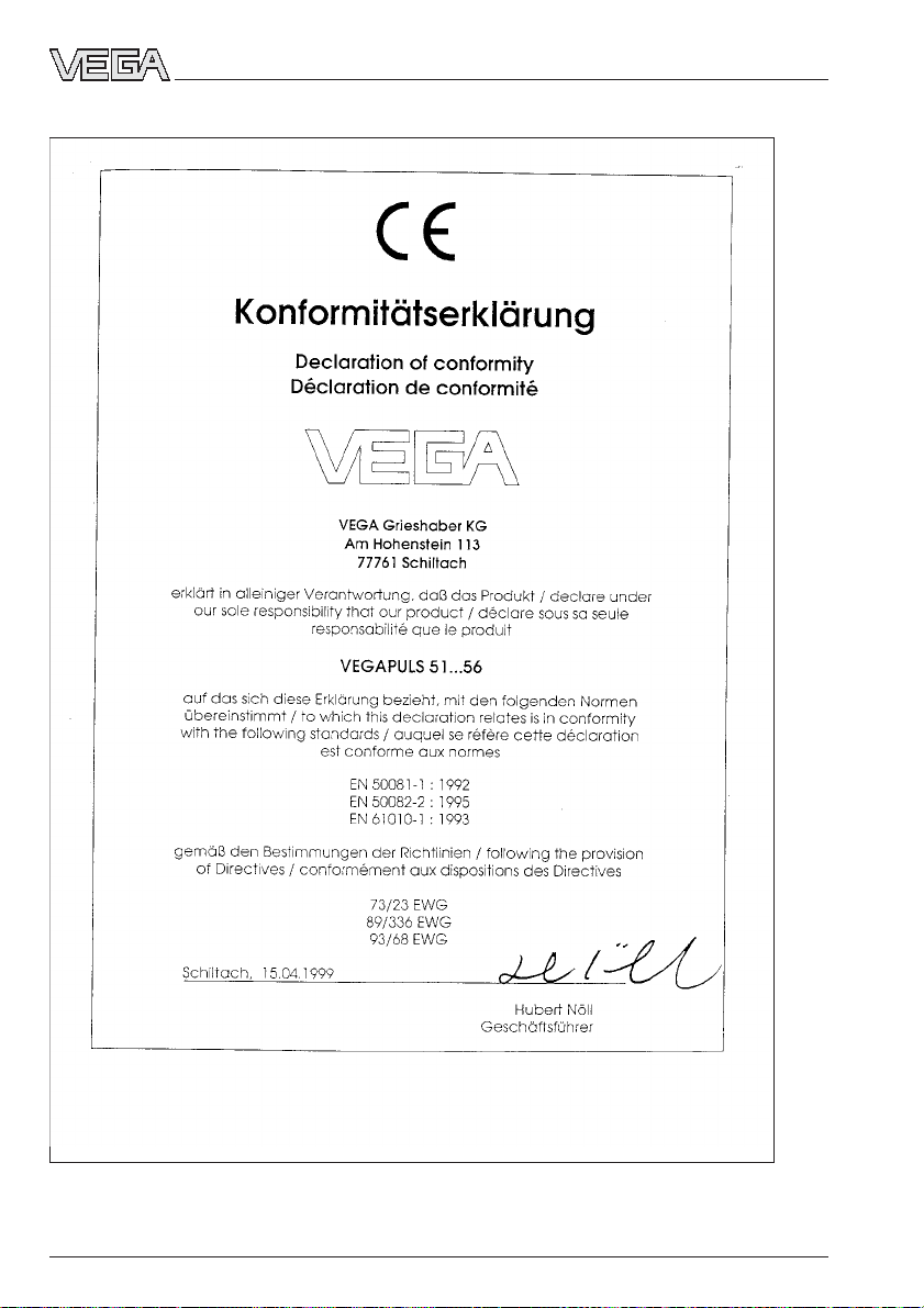
CE declaration of conformity
Supplement
70 VEGAPULS 51K … 54K
21750-EN-031222
Page 71

Supplement
21750-EN-031222
VEGAPULS 51K … 54K 71
Page 72

VEGA Grieshaber KG
Am Hohenstein 113
77761 Schiltach
Germany
Phone (07836) 50-0
Fax (07836) 50-201
E-Mail info@de.vega.com
www.vega.com
ISO 9001
All statements concerning scope of delivery, application, practical
use and operating conditions of the sensors and processing systems correspond to the information available at the time of printing.
Technical data subject to alterations
21750-EN-031222
 Loading...