

Page 1
Operating Instructions
VEGAPULS 42, 44 and 45 – VBUS
Level and Pressure
Page 2

Contents
Safety information ........................................................................ 3
Note Ex area ................................................................................ 3
1 Product description
1.1 Function................................................................................. 4
1.2 Application features ............................................................. 6
1.3 Adjustment ............................................................................ 6
2 Types and versions
2.1 Overview .............................................................................. 9
2.2 Type code........................................................................... 11
2.3 Antennas............................................................................. 12
3 Mounting and installation
3.1 General installation instructions ........................................ 14
3.2 Measurement of liquids ..................................................... 16
3.3 Measurement in standpipe (surge or bypass tube) ...... 18
3.4 False echoes ...................................................................... 25
3.5 Installation mistakes ........................................................... 27
Contents
4 Electrical connection
4.1 Connection and connection cable .................................... 30
4.2 Connection of the sensor .................................................. 33
4.3 Connection of the external indicating instrument
VEGADIS 50 ....................................................................... 34
4.4 Configuration of measuring systems ............................... 35
2 VEGAPULS 42, 44 and 45 – VBUS
Page 3

Contents
5Setup
5.1 Adjustment structure ......................................................... 42
5.2 Adjustment with the PC on the signal
conditioning instrument ...................................................... 43
5.3 Adjustment with VEGAMET or MINICOM ........................ 69
5.4 Adjustment with the PC on VEGALOG ............................ 76
6 Diagnosis
6.1 Simulation ............................................................................ 82
6.2 Error code .......................................................................... 82
7 Technical data
7.1 Data ..................................................................................... 83
7.2 Approvals ........................................................................... 88
7.3 Dimensions ......................................................................... 89
Safety information
Please read this manual carefully, and also take
note of country-specific installation standards
(e.g. the VDE regulations in Germany) as well
as all prevailing safety regulations and accident prevention rules.
For safety and warranty reasons, any internal
work on the instruments, apart from that involved in normal installation and electrical connection, must be carried out only by qualified
VEGA personnel.
VEGAPULS 42, 44 and 45 – VBUS 3
Note Ex area
Please note the attached safety instructions
containing important information on installation
and operation in Ex areas.
These safety instructions are part of the operating instructions and come with the Ex approved instruments.
Page 4
1 Product description
Product description
VEGAPULS series 40 sensors are a newly
developed generation of very compact, small
radar sensors for high resolution and accuracy. They are characterised by special
focusing features for level measurement in
narrow space applications. With modest
space requirements they were developed for
measuring distances of 0 … 4 m/10 m/20 m
and for standard applications such as storage vessels and buffer tanks as well as for
process tanks. With small housing dimensions and process fittings, the compact sensors monitor your levels at reasonable cost.
With the integrated display they enable high
precision level measurements and due to
their advantages, radar sensors have
increasingly become the standard solution
for many applications, even for those where it
was previously unthinkable due to high
costs.
VEGAPULS 40 radar sensors utilise two-wire
technology perfectly. The supply voltage and
the output signal are transmitted via one twowire cable. They provide a digital output
signal (VBUS or Profibus) or an analogue
4 … 20 mA signal as output or measuring
signal.
This operating instruction manual relates
to VEGAPULS 42, 44 and 45 sensors with
digital VBUS output signal (VEGA-Bus).
1.1 Function
Radio detecting and ranging: Radar.
VEGAPULS radar sensors are used for noncontact, continuous distance measurement.
The measured distance corresponds to a
filling height and is outputted as level.
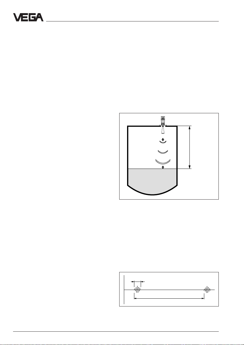
Measuring principle:
emission – reflection – reception
Tiny 26 GHz radar signals are emitted from
the antenna of the radar sensor as short
pulses. The radar impulses reflected by the
sensor environment and the product are
received by the antenna as radar echoes.
The running period of the radar impulses
from emission to reception is proportional to
the distance and hence to the level.
Meas.
distance
emission - reflection - reception
The radar impulses are emitted by the antenna system as pulse packages with a
pulse duration of 1 ns and pulse intervals of
278 ns; this corresponds to a pulse package
frequency of 3.6 MHz. In the impulse intervals, the antenna system operates as receiver. Signal running periods of less than
one billionth of a second must be processed
and the echo image evaluated in a fraction of
a second.
1 ns
278 ns
Pulse sequence
4 VEGAPULS 42, 44 and 45 – VBUS
Page 5
Product description
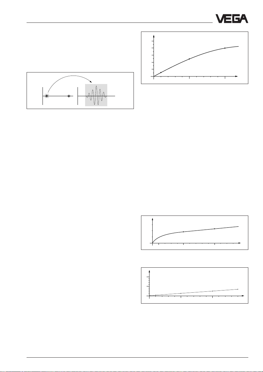
VEGAPULS radar sensors can accomplish
this through a special time transformation
procedure which spreads out the more than
3.6 million echo images per second in a slowmotion picture, then freezes and processes
them.
tt
Time transformation
Hence, it is possible for the VEGAPULS radar sensors to process the slow-motion
pictures of the sensor environment precisely
and in detail in cycles of 0.5 to 1 second
without using time-consuming frequency
analysis (e.g. FMCW, required by other radar
techniques).
Virtually all products can be measured
Radar signals are physically similar to visible
light. According to the quantum theory they
propagate through empty space and are
therefore not dependent, like e.g. sound
waves, on a conductive medium. And like all
electromagnetic waves, they travel at the
speed of light.
The radar signals react to two primary
electrical properties:
- the electrical conductivity of a substance.
- the dielectric constant of a substance.
All products which are electrically conductive
or have a dielectric constant greater than ε
1.6 have sufficiently good reflection charac-
r
teristics for reliable radar measurement.
(Note: air has a dielectric constant ε
The signal reflection increases with the con-
of 1).
r
ductivity or with the dielectric constant of the
product. Therefore virtually all products can
be measured.
%
50
40
30
20
10
5 %
5
0
2
4 6 8 12 14 16 18
0
25 %
10
40 %
20
ε
r
Reflected radar power dependent on the dielectric
constant of the measured product
With standard flanges between DN 50 and
DN 150, ANSI 2" to ANSI 6" or G 1½ A and
1½" NPT the sensor antenna systems are
adapted to the various products and measuring environments.
High quality materials withstand also extreme
chemical and physical conditions. The sensors deliver reliable, precise and long-term
stable, reproducible level signals.
Continuous and reliable
Unaffected by temperature, pressure and
individual gas atmospheres, VEGAPULS
radar sensors are used for quick and reliable
continuous level measurement of various
products.
%
0,03
0,02
0,01
0
100 500 1000 1300 ˚C
0
0,018 %
Temperature influence: Temperature error absolutely
zero (e.g. at 500°C 0.018 %)
%
10
5
0,29 %
0
10
0
1,44 %
20 30 40 60
50
Pressure influence: Error with pressure increase very
low (e.g. at 50 bar 1.44 %)
0,023 %
2,8 %
70 80 90 110 120 130 140
100
3,89 %
bar
VEGAPULS 42, 44 and 45 – VBUS 5
Page 6
Product description
1.2 Application features
Applications
• Level measurement of all liquids.
• Measurement also in vacuum.
• All slightly conductive substances and all
substances with a dielectric constant > 2.0
can be measured.
• Measuring range 0 … 10 m (type 42).
Measuring range 0 … 20 m (type 44).
Measuring range 0 … 4 m (type 45).
Two-wire technology
• Power supply and output signal on one
two-wire cable (loop powered).
• VBUS output signal (VEGA-Bus).
Rugged and wear-free
• Non-contact.
• High resistance materials.
Exact and reliable
• Accuracy 0.05 %.
• Resolution 1 mm.
• Unaffected by noise, steam, dust, gas
compositions and inert gas stratification.
• Unaffected by varying density and temperature of the medium.
• Measurements of pressures up to 40 bar
and temperatures up to 150 °C.
1.3 Adjustment
Each measuring situation is unique. For that
reason, every radar sensor needs some
basic information on the application and the
environment, e.g. which level means "empty"
and which level "full". Beside this "empty and
full adjustment", many other settings and
adjustments are possible with VEGAPULS
radar sensors.
Adjustment and parameter setting of the
radar sensors is done with
- the PC and the adjustment program VVO
- the detachable adjustment module
MINICOM
- the VEGAMET signal conditioning instrument
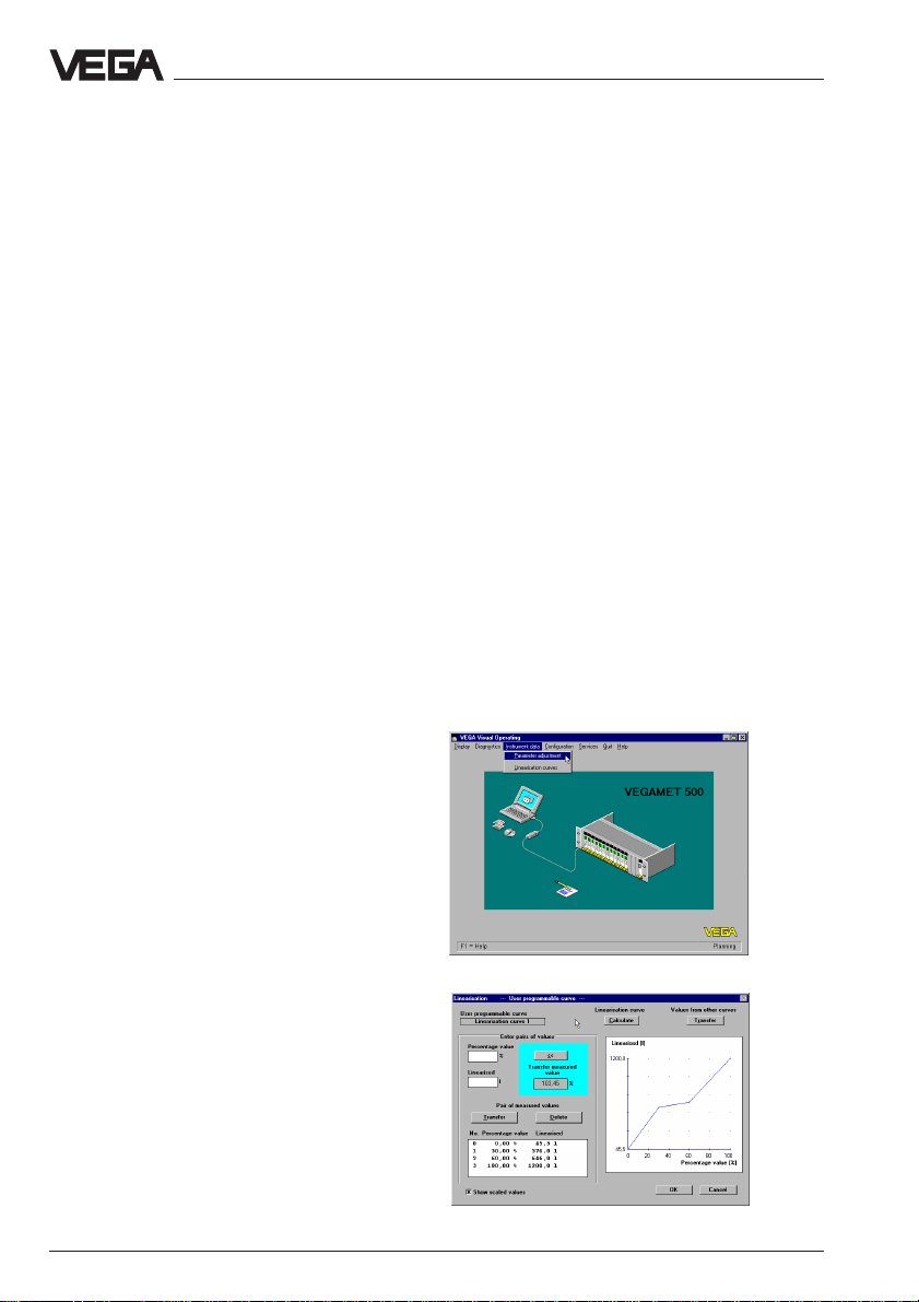
Adjustment with the PC
Setup and adjustment of the radar sensors is
generally done on the PC with the adjustment
program VEGA Visual Operating (VVO)
under Windows
graphics and process visualisation, the program leads you quickly through adjustment
and parameterisation.
®.
By means of pictures,
Communicative
• Integrated display of measured values.
• Optional display separate from the sensor.
• Adjustment with detachable adjustment
module which can be plugged into the
sensor or into the external display.
• Adjustment with signal conditioning instrument.
• Adjustment with PC.
Approvals
The adjustment program recognises the sensor type
• CENELEC, ATEX, PTB, FM, CSA, ABS,
LRS, GL, LR, FCC, RINA.
Visualised creation of a vessel linearisation curve
6 VEGAPULS 42, 44 and 45 – VBUS
Page 7
Product description
Note:
The adjustment program VVO must be available in version 2.70 or higher.
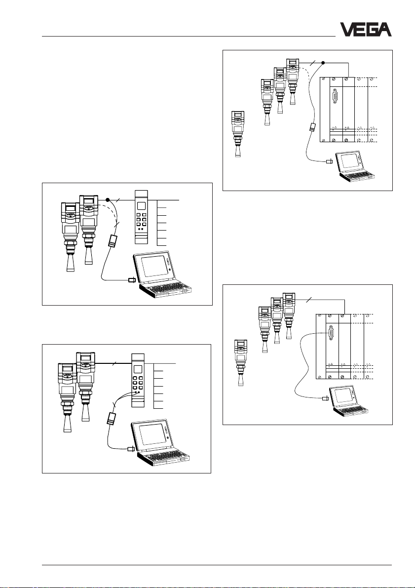
The PC can be connected to any position of
the system or the signal cable. It is connected with the two-wire PC interface converter VEGACONNECT 2 to th e sensor, the
signal cable or the signal conditioning instrument. The sensor is connected directly to the
VEGALOG processing system with the
standard cable (RS 232).
2
2
Adjustment with the PC on the digital signal and
supply cable between sensors and VEGAMET signal
conditioning instrument or directly on the sensor
2
…
…
1 ... 15
CPU
VEGALOG
VEGALOG
571 CPU
571 EA
Adjustment on the digital signal and supply cable to
the VEGALOG 571 processing system or directly on
the sensor
The adjustment and parameter setting data
can be saved on the PC with the adjustment
software and protected by passwords. The
adjustments can be quickly transferred to
other sensors if required.
2
......
CPU
2
1...15
VEGALOG
VEGALOG
571 CPU
571 EA
2
Adjustment with the PC on the VEGALOG processing
system with standard cable RS 232 (up to 15 sensors
can be operated on one two-wire cable with the
processing system)
Adjustment with the PC on the VEGAMET signal
conditioning instrument, to which one or two sensors
can be connected
VEGAPULS 42, 44 and 45 – VBUS 7
Page 8
Product description
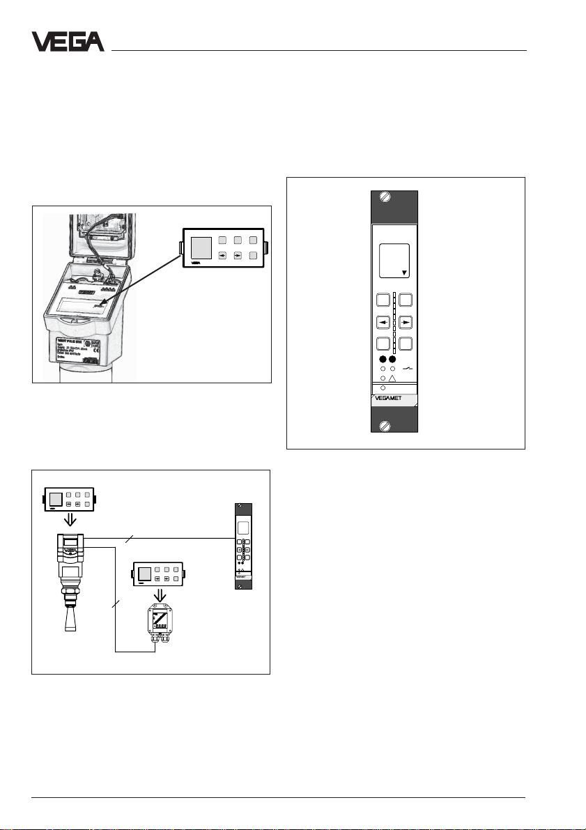
Adjustment with adjustment module
MINICOM
With the small (3.2 cm x 6.7 cm) 6-key adjustment module with display you carry out
the adjustment in clear text dialogue. For this
purpose, the adjustment module can be
plugged into the radar sensor or into the
optional external indicating instrument.
Tank 1
m (d)
12.345
Detachable adjustment module MINICOM
Unauthorised sensor adjustments can be
prevented by removing the adjustment module.
ESC
+
-
Tank 1
m (d)
OK
12.345
2
ESC
+
-
Tank 1
m (d)
OK
12.345
4
ESC
+
-
OK
%
100
+
-
OK
ESC
CONNECT
!
on
513
Adjustment with the VEGAMET signal
conditioning instrument
The radar sensors with digital output signal
can be adjusted, besides with the PC, also
with the VEGAMET signal conditioning instrument.
%
100
+
-
OK
ESC
CONNECT
12
!
on
515V
6-key adjustment field on the instrument front of the
VEGAMET signal conditioning instrument
For adjustment, the digital VEGAMET 514V
and 515V signal conditioning instruments are
provided with a 6-key adjustment field with
display. Here you can carry out the parameter setting in clear text dialogue. Using the
6-key adjustment field, it is also possible to
adjust one or two connected sensors with the
signal conditioning instrument. The
adjustment scheme corresponds to that of
the adjustment module MINICOM.
Adjustment with detachable adjustment module. The
adjustment module can be plugged into the radar
sensor or into the external indicating instrument
VEGADIS 50.
8 VEGAPULS 42, 44 and 45 – VBUS
Page 9
Types and versions
2 Types and versions
2.1 Overview
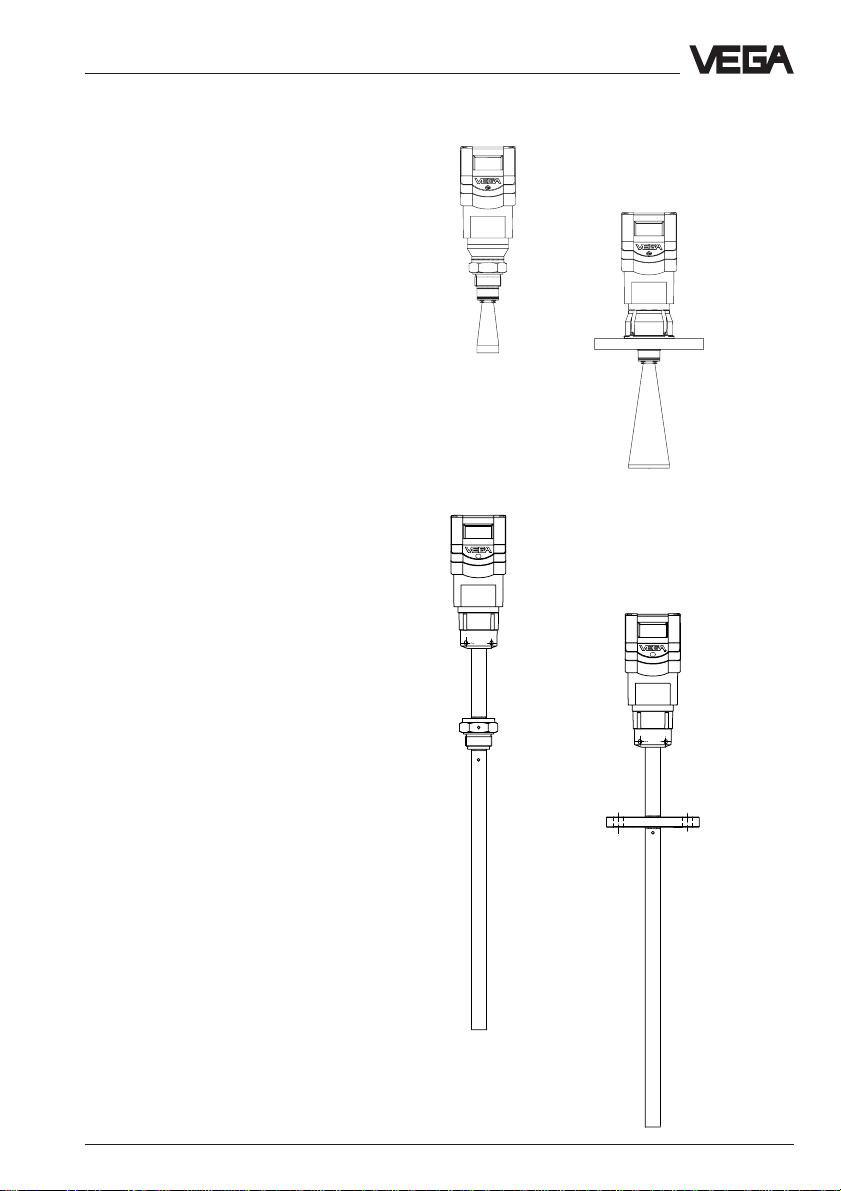
Series 40 sensors are manufactured in three
basic versions, VEGAPULS 42, VEGAPULS
44 and VEGAPULS 45.
VEGAPULS 42 sensors are characterised by
1
G 1
/2 A or 11/2" NPT thread as process fitting.
These sensors are equipped as standard
versions with a ø 40 mm horn as antenna.
VEGAPULS 44 sensors are characterised by
a DIN or ANSI flanges as process fitting. In
standard version they are manufactured with
DN 50, 80, 100 and 150 as well as with ANSI
2", 3", 4" and 6". The bigger flanges come
equipped with respectively larger antenna
horns (ø 48, 75 and 95 mm).
Generally: The bigger the antenna horn, the
better the focusing characteristics, and the
better the antenna gain. This ensures that
even a weak product echo can be detected
reliably as level echo.
VEGAPULS 45 sensors come completely
equipped with a measuring tube of 4 m
length. These sensors are used in
applications where high accuracy is required
or for liquids with very low dielectric constant
such as e.g. liquid gas.
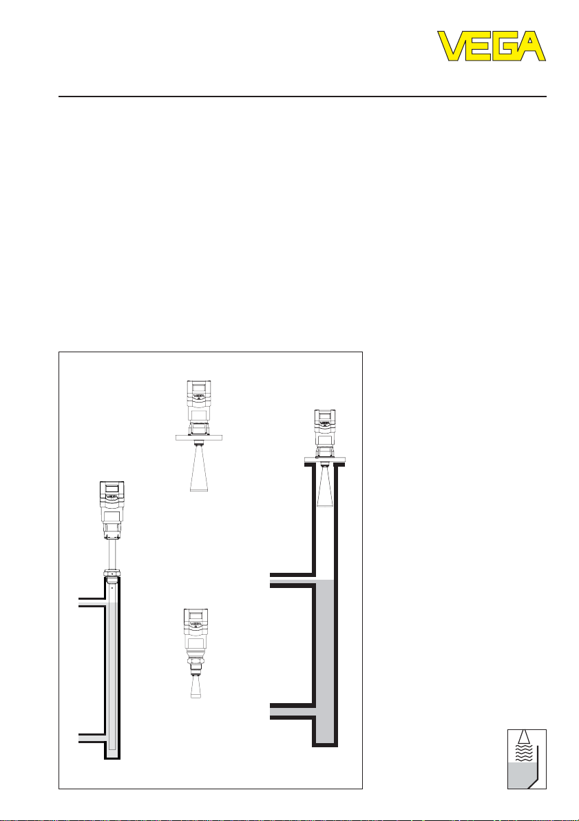
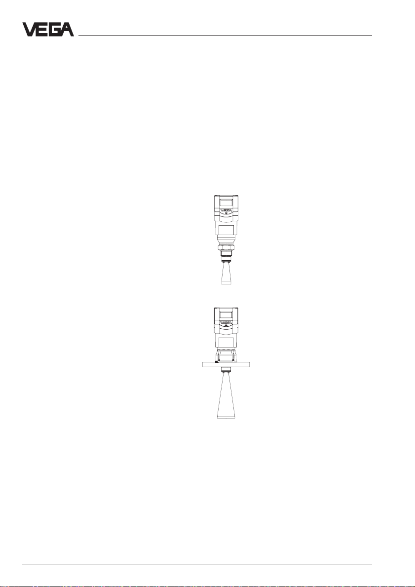
VEGAPULS 42
VEGAPULS 45
with thread
G 1½ A or 1½"
NPT
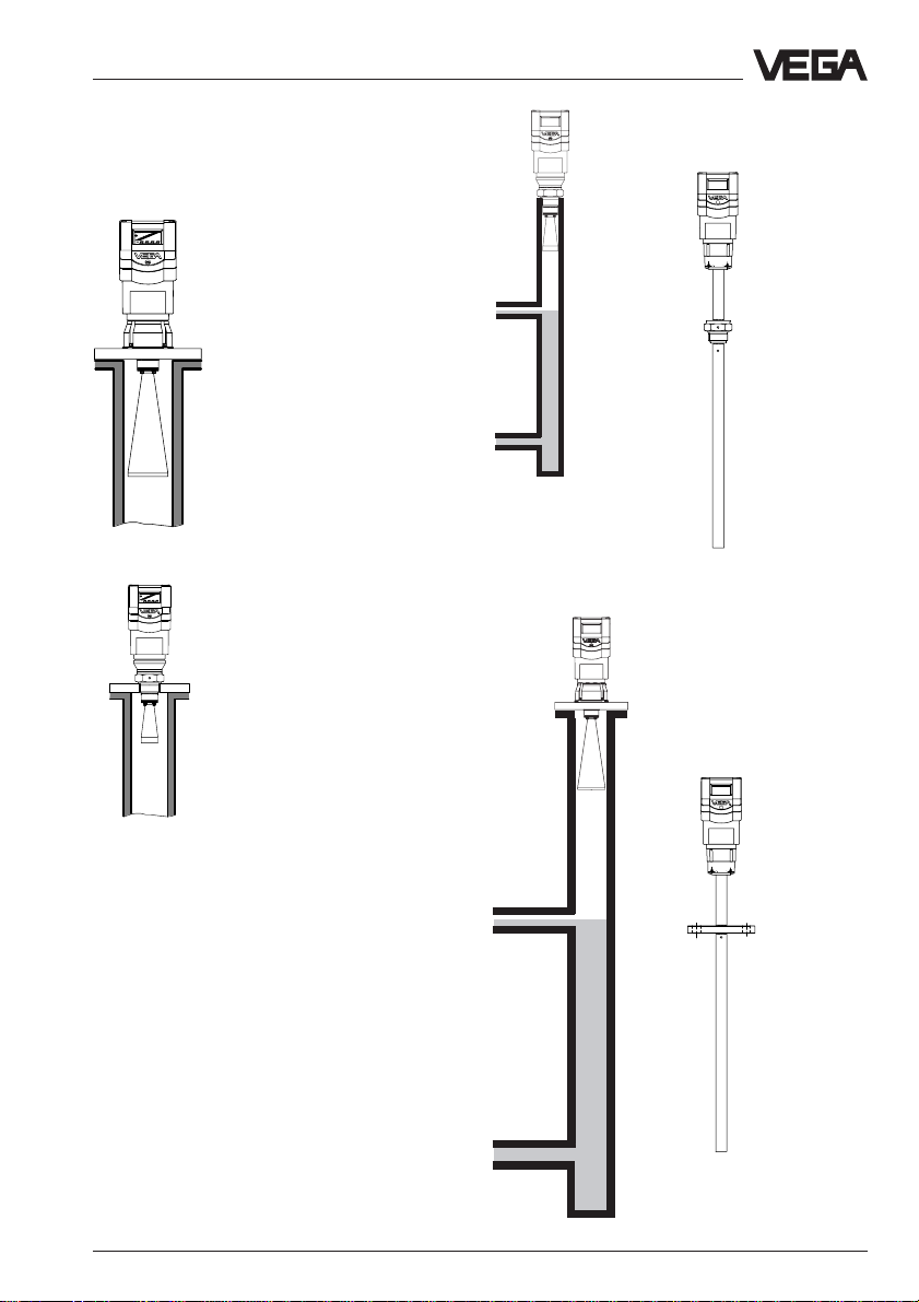
VEGAPULS 44
VEGAPULS 45
with flange
VEGAPULS 42, 44 and 45 – VBUS 9
Page 10

Types and versions
Features
General features
• Measurement preferably of liquids in storage tanks or process vessels with increased
accuracy requirement.
• Measuring range 0 … 4 m, 0 … 10 m or 0 … 20 m.
• Ex approved in Zone 1 (IEC) or Zone 1 (ATEX) classification mark
EEx ia [ia] IIC T6.
• Integrated display of measured values.
Overview
PS42XXE… PS44XXE… PS45XXXE…
Signal output
- VBUS (VEGA-Bus) • • •
Antenna
- horn antenna • • –
- pipe antenna
1) 1)
•
Process fitting
- G 1½ A; 1½" NPT • – •
- DN 50; ANSI 2" – • •
- DN 80; ANSI 3" – • •
- DN 100; ANSI 4" – • •
- DN 150; ANSI 6" – • •
Adjustment
-PC •••
- adjustment module in the sensor • • •
- adjustment module in external
indicating instrument • • •
- with signal conditioning instrument • • •
Measuring range 0 … 4 m
- ø 40 mm horn 0 … 10 m – (depending on the
- ø 48 mm horn 0 … 15 m 0 … 15 m tube length)
- ø 75 mm horn 0 … 20 m 0 … 20 m
- ø 95 mm horn 0 … 20 m 0 … 20 m
1)
When mounting on a standpipe or bypass tube, a pipe antenna is created. The tube inner diameter should be
between 40 mm and 80 mm.
10 VEGAPULS 42, 44 and 45 – VBUS
Page 11
Types and versions
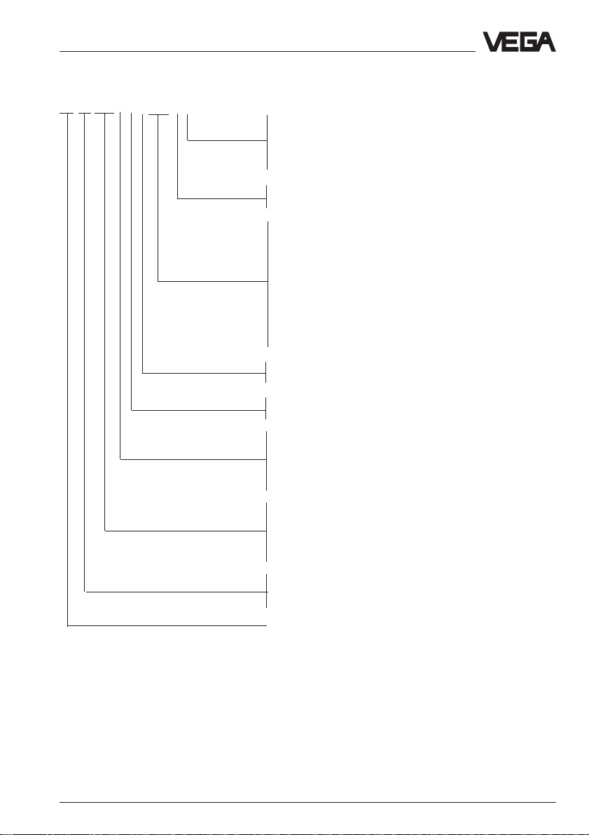
2.2 Type code
PS 42 .XX X X X XXX X X
K - Plastic housing PBT, M20 x 1.5 cable entry
N - Plastic housing PBT, ½" NPT cable entry
A - Aluminium housing, M20 x 1.5 cable entry
D - Aluminium housing, ½" NPT cable entry in Exd connection
housing
V - Seal of the antenna system: Viton
A - Seal of the antenna system: Kalrez
G - Process fitting G 1½
N - Process fitting 1½" NPT
A
ABC- Process fitting DN 50 PN 40
BBE- Pr ocess fitting DN 80 PN 40
CBG-Process fitting DN 100 PN 16
DBG-Process fitting DN 150 PN 16
ARC- Process fitting ANSI 2" 150 psi
BRE- Pr ocess fitting ANSI 3" 150 psi
CRG-Process fitting ANSI 4" 150 psi
DRG-Process fitting ANSI 6" 150 psi
YYY- Process fitting on request
X - without display
A - with integrated display
X - without adjustment module MINICOM
B - with adjustment module MINICOM (mounted)
B - 20 … 72 V DC; 20 … 250 V AC; 4 … 20 mA, HART
(four-wire)
D - Two-wire (loop powered), 4 … 20 mA, HART
®
®
E - Power supply via signal conditioning instrument
G - Segment coupler for Profibus PA
XX - FTZ (standard telecommunication approval Germany)
AX - Approval in Ex-Zone 1, EEx ia IIC T6
CX - Approval in Ex-Zone 0, EEx ia IIC T6
BX - Approval in Ex-Zone 1 (Exd connection housing)
DX - Approval in Ex-Zone 0 (Exd connection housing)
Type 42: with screwed process fitting
Type 44:Instrument series with flange connection
Type 45: with measuring tube
PS: Radar sensors series 40
VEGAPULS 42, 44 and 45 – VBUS 11
Page 12
Types and versions
2.3 Antennas
The antenna is the eye of the radar sensor. A
casual observer would never guess how
carefully the antenna geometry must be
adapted to the physical properties of electromagnetic fields. The geometrical form determines focal properties and sensitivity - the
same way it determines the sensitivity of a
unidirectional microphone.
For various application purposes, measurement conditions and process requirements,
series 40 sensors are available with three
antenna forms as VEGAPULS 42,
VEGAPULS 44 and VEGAPULS 45.
VEGAPULS 42 sensors are characterised by
1
G 1
/2 A or 11/2" NPT thread as process fitting.
These sensors are equipped as standard
versions with a ø 40 mm horn as antenna.
VEGAPULS 44 sensors are characterised by
a DIN or ANSI flanges as process fitting. In
standard version they are manufactured with
DN 50, 80, 100 and 150 as well as with ANSI
2", 3", 4" and 6". The bigger flanges come
equipped with respectively larger antenna
horns (ø 48, 75 and 95 mm).
Generally: The bigger the antenna horn, the
better the focusing characteristics, and the
better the antenna gain. This ensures that
even a weak product echo can be detected
reliably as level echo.
VEGAPULS 45 sensors are characterised by
integrated measuring tube. The measuring
tube serves the radar signals as a
waveguide in which no emitted energy is lost.
The complete emitted energy is returned as
reflection energy. Due to this, also products
with very weak reflection characteristics,
such as light petrol, liquid gas with
of 1.4 … 2.0 can be reliably detected.
ε
values
r
Viscous or adhesive products cannot be
measured with VEGAPULS 45.
Horn antennas
Horn antennas focus the
radar signals very well.
Manufactured from 1.4435
(StSt) or Hastelloy C22, they
are very rugged, and both
physically and chemically
resistant. They are suitable
for pressures up to 40 bar
and for medium temperatures up to 150°C. The horn
VEGAPULS 42
diameters determine the
focusing of the radar signals. The antenna gain increases with increasing horn
diameter (40, 48, 75,
95 mm).
The antenna gain represents
the relation between
transmitted energy and
received echo energy.
VEGAPULS 44
12 VEGAPULS 42, 44 and 45 – VBUS
Page 13
Types and versions
Pipe antennas
Pipe antennas composed of horn antenna
and standpipe or bypass tube
Horn antennas on a standpipe or bypass tube form a
complete antenna system in
conjunction with a measuring
pipe (which must not be
perfectly straight, but can
also have bends). For the
radar signals, the measuring
pipe acts as a conductor.
The running time of the radar
signal changes in the pipe
and depends on the pipe
diameter. The sensor must
be therefore informed about
the tube inner diameter so
that the running time can be
taken into account and
precise level signals are
delivered. Pipe antennas are
best suited for turbulent
applications and products
with very low dielectric constant.
The antennas are
characterised by a very high
antenna gain. As a result,
high reliability is achieved
even with products having
very poor reflection properties.
VEGAPULS 42
pipe antenna
composed of
horn antenna and
bypass tube
VEGAPULS 44
pipe antenna
composed of
horn antenna and
bypass tube
VEGAPULS 45
with thread, pipe
antenna integrated in the
sensor
VEGAPULS 45
with flange, pipe
antenna integrated in the
sensor
Pipe antenna integrated in the sensor
VEGAPULS 45 series originated as a further
development of VEGAPULS 42 and 44
sensors combined with a surge pipe or
bypass tube. This sensor is equipped with
an optimised measuring tube up to 4 m long
and enables high precision level
measurement also in products with very
small dielectric figures of ε
liquid gas).
VEGAPULS 42, 44 and 45 – VBUS 13
= 1,4 … 1,8 (e.g.
r
Page 14
3 Mounting and installation
3.1 General installation instructions
Mounting and installation
Measuring range
The reference plane for the measuring range
of the sensors is the flange face or the seal
shoulder of the thread. For measurements in
Keep in mind that in measuring environments
where the medium can reach the sensor
flange, buildup can occur on the antenna and
can cause measurement errors.
surge or bypass pipes with VEGAPULS 45
the max. measuring distance depends on the
tube length.
Reference
plane
max. filling
Measuring range (operating range) and max. measuring distance
Note: Use of the sensors for applications with solids is limited.
full
empty
Meas. range
max. measuring distance 20 m (type 45: 4 m)
Note: The use of series 40 sensors for solids
is restricted.
max.
min.
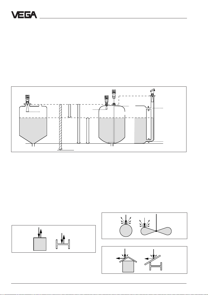
Interfering reflections
Flat obstructions and struts cause large
interfering reflections. They reflect the radar
signal with high energy density.
Rounded profile interfering surfaces scatter
the radar signals in all directions and thus
cause interfering reflections of lower energy
density. Hence, they ar e less critical than
reflections from a flat surface.
If flat obstructions in the range of the radar
signals cannot be avoided, we recommend
diverting the interfering signals with a deflec-
tor. Through scattering, the interfering signals
will be low in amplitude and so diffuse that
they can be filtered out by the sensor.
max.
max.
min.
Rounded profiles diffuse radar signals
Profiles with flat surfaces cause stronger interfering
signals
A deflector causes signal scattering
14 VEGAPULS 42, 44 and 45 – VBUS
Page 15
Mounting and installation
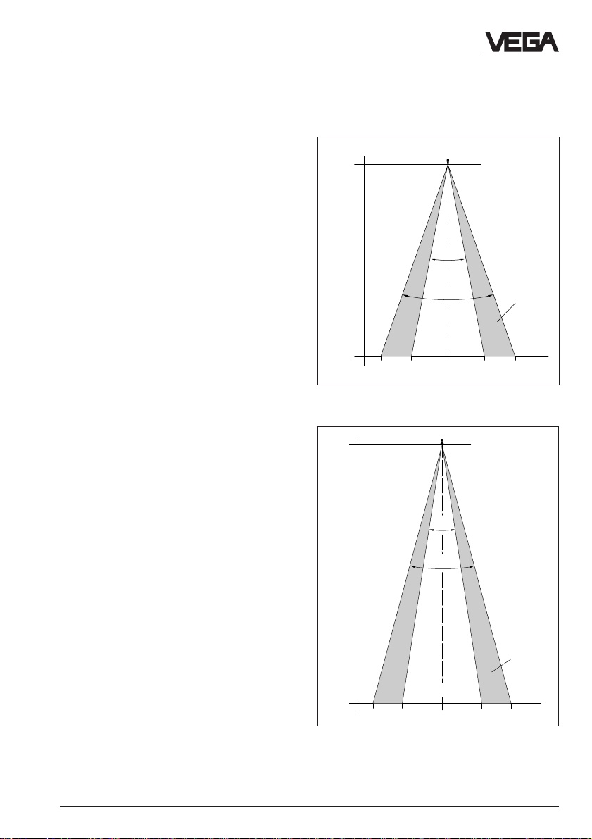
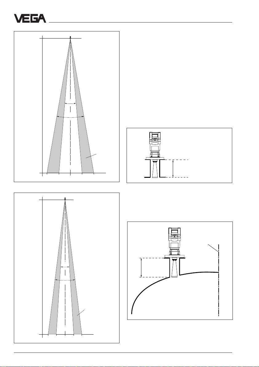
Emission cone and interfering reflections
The radar signals are focused by the antenna system. The signals leave the antenna
in a conical path similar to the beam pattern
of a spotlight. The form and intensity of the
emission cone depend on the antenna used.
Any object in this beam cone causes a reflection of the radar signals. Within the first few
meters of the beam cone, tubes, struts or
other installations can interfere with the measurement. At a distance of 6 m, the false echo
of a strut has an amplitude nine times greater
than at a distance of 18 m.
At greater distances, the energy of the radar
signal distributes itself over a larger area,
thus causing weaker echoes from obstructing surfaces. The interfering signals are
therefore less critical than those at close
range.
If possible, orient the sensor axis perpendicularly to the product surface and avoid
vessel installations within the 100 % area of
the emission cone, e.g. tubes or struts.
The illustrations of the emission cones are
simplified and represent only the main beam
- a number of weaker beams also exist. Under difficult measuring conditions, the alignment of the antenna must be such that the
lowest possible false echo values appear.
Only giving attention to the size of the useful
echo is not always adequate when measuring conditions are unfavourable.
Optimum measuring conditions exist when
the emission cone reaches the measured
product perpendicularly and when the emission cone is free of obstructions.
0 m
Meas.
distance
10 m
Emission cone of a VEGAPULS 42 with screw-on
antenna and with ø 40 mm horn
Meas.
distance
3,50 1,90 3,501,900
0 m
VEGAPULS 42
22˚
30˚
50%
18˚
25˚
25%
VEGAPULS 44 with
ø 48 mm horn
m
In a difficult measurement environment,
searching for a mounting location with the
lowest possible false echo intensity will bring
the best results. In most cases, the useful
echo will then be present with sufficient
strength. With the adjustment software VVO
25%
on the PC, you can have a look at the echo
image and optimise the mounting location
(see chapter "5.2 Adjustment with the PC –
Sensor optimisation – Echo curve").
If possible, provide a "clear view" to the prod-
15 m
4,0 2,3 4,02,30
Emission cone of a DN 50 flange antenna
50%
m
uct inside the emission cone and avoid vessel installations in the first third of the
emission cone.
VEGAPULS 42, 44 and 45 – VBUS 15
Page 16
Mounting and installation
0 m
Meas. distance
20 m
3,0 1,7 3,01,70m
VEGAPULS 44 with
ø 75 mm horn
10˚
20˚
50%
Emission cone of a DN 80 flange antenna
0 m
VEGAPULS 44 with
ø 95 mm horn
25%
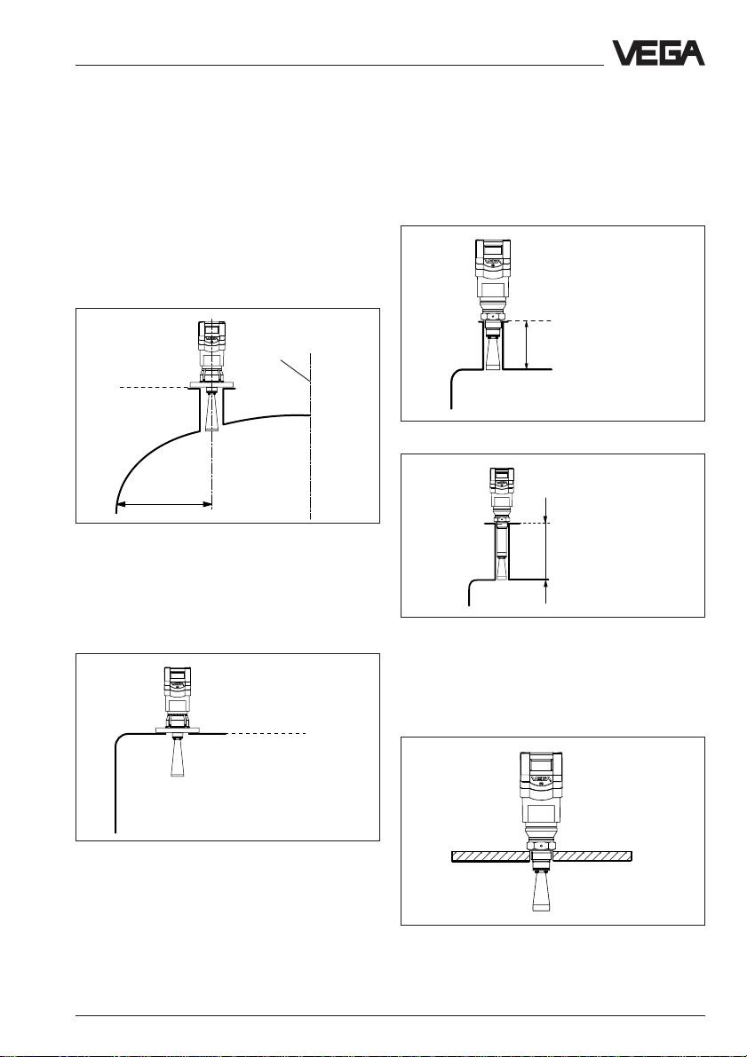
3.2 Measurement of liquids
Flange antennas
In most cases, the mounting of radar sensors
is done on short DIN socket pieces. The
lower side of the instrument flange is the
reference plane for the measuring range. The
antenna must always protrude out of the
flange tube.
When the DIN socket piece is longer, please
make sure that the horn antenna is not cov-
ered completely by the socket. It is better if
the antenna protrudes slightly out of the
socket.
Reference plane
< 135 mm (DN 50)
< 210 mm (DN 80)
< 310 mm (DN 100, DN 150)
Mounting on DIN socket piece
When mounting on dished vessel tops, the
antenna length should at least correspond to
the length of the longer sockets.
Vessel center or
symmetry axis
Meas. distance
8˚
14˚
25%
<135…310mm
(250…425mm
with antenna
extension)
Mounting on a dished vessel top; max. socket length
20 m
2,5 1,3 2,51,30
50%
m
depending on flange size and, if applicable, on the
length of the antenna extension (see "7.3 Dimensions").
Emission cone of a DN 100 and DN 150 flange antenna
16 VEGAPULS 42, 44 and 45 – VBUS
Page 17
Mounting and installation
On dished tank ends, please do not mount
the instrument in the centre or close to the
vessel wall, but approx.
1
/2 vessel radius from
the centre or from the vessel wall.
Dished tank ends can act as paraboloidal
reflectors. If the radar sensor is placed in the
focal point of the parabolic tank, the radar
sensor receives amplified false echoes. The
radar sensor should be mounted outside the
focal point. Parabolically amplified echoes
can be thereby avoided.
Vessel center or
symmetry axis
Reference plane
½ vessel radius
Mounting on dished tank ends
If the stability of the vessel will allow it (sensor
weight), flat mounting directly on the vessel
top is a good and economical solution. The
top side of the vessel is the reference plane.
Screw-on antenna
The screw-on antenna is mainly used on
small vessels. The antenna fits on small vessel openings down to 1
must not be longer than 135 mm (when using
the longer antenna, not longer than 250 mm).
Screw-on antenna on socket piece 11/2"
Screw-on antenna with antenna extension on socket
piece 1½"
1
/2" socket. The socket
Reference plane
≤ 135 mm
≤ 250 mm
As an alternative to socket mounting, the
screw-on antenna can be screwed into the
Reference plane
Mounting directly on the flat vessel top
VEGAPULS 42, 44 and 45 – VBUS 17
hole in the vessel.
Rod antenna directly on vessel opening
Page 18
Mounting and installation
3.3 Measurement in standpipe
(surge or bypass tube)
General instructions
Pipe antennas are preferred in vessels which
contain many installations, e.g. heating tubes,
heat exchangers or fast-running stirrers.
Measurement is then possible where the
product surface is very turbulent, and vessel
installations cannot cause false echoes.
Through the focusing of the radar signals
within the measuring tube, even products
with low dielectric constant (ε
be measured reliably in the surge or bypass
tube. Note the following instructions.
Surge pipe welded
to the tank
Type label
= 1.6 to 3) can
r
Surge pipe in the
socket piece
maxmax
Make sure the required upper vent hole in
the surge pipe is aligned with the sensor
type label.
As an alternative to a surge pipe in the ves-
sel, a pipe antenna system outside the ves-
sel in a bypass tube is also possible.
The surge and bypass tubes must generally
be made of metal. For plastic tubes, a
closed, conductive jacket is always required.
For metal tubes with plastic inner coating,
make sure that the thickness of the coating is
minimal (approx. 2 … 4 mm).
Align the sensor such that the type label lies
on one axis with the tube holes or the tube
connection openings. The polarisation of the
radar signal enables a considerably more
stable measurement with this alignment.
Type label
> 300 mm
100 %
Vent hole
ø 5 … 10 mm
0 %
Tube flange system as bypass tube
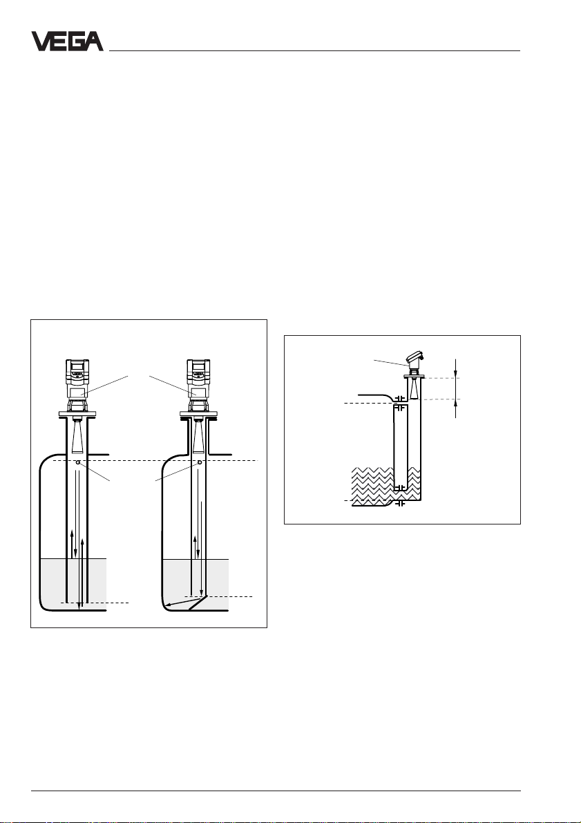
When mounting a VEGAPULS 42 or 44 sen-
sor on a bypass tube (e.g. on a previous
min
without deflector
Pipe antenna systems in the tank
with deflector
min
floating or displacer unit), the radar sensor
should be mounted at a distance of approx.
300 mm or more from the max. level.
The surge or bypass tubes open at the bottom should reach to the requested min. level,
since a reliable measurement is only possible
within the pipe. The tube inner diameter
should be max. 100 mm and correspond with
the size of the antenna horn.
18 VEGAPULS 42, 44 and 45 – VBUS
Page 19
Mounting and installation
> 300 mm
100 %
75 %
0 %
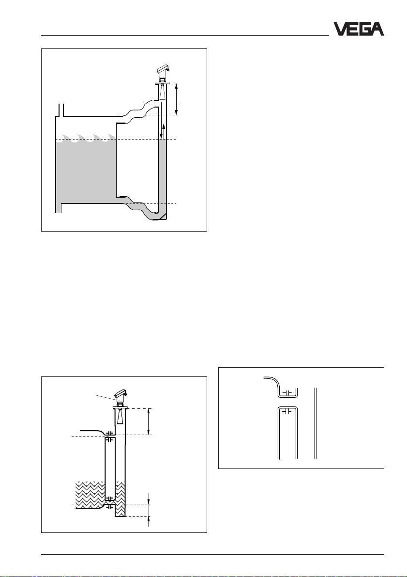
Extended bypass tube on a vessel with intense
product movements
For products with small dielectric constants
(< 4), a bypass tube longer than that required by the lower tube connection should
be used. Products with small dielectric constants are partly penetrated by the radar
signals, so that the tube bottom delivers a
stronger echo than the product (when the
bypass tube is nearly empty). As a result of
the extension of the lower tube end, sufficient
liquid will remain even when the vessel is
emptied.
With a liquid quantity of 300 … 800 mm in the
blind lower end of the tube, the portion of the
signal that penetrates the liquid and reflects
from the tube bottom is sufficiently damped the sensor can then easily distinguish it from
the echo of the liquid surface. If not enough
liquid remains, a deflection plate located at
the bottom of a vertical pipe can provide the
same function. It deflects the signal reflected
from the tube end sideways into the standard
tube opening.
Connections to the bypass tube
The connections to the bypass tubes must
be fashioned in such a way that only minimal
reflections are caused by the walls of the
connecting tubes. This is especially important
for the breather connection in the upper part
of the tube. Observe the following points:
• Use small openings for the connection.
• The diameter of the connecting tubes
should not exceed 1/3 of the bypass diameter.
• The tube connections must not protrude
into the bypass.
• Large welding beads in the tubes should
be avoided.
• Additional connections to the bypass tube
are more suitable if they lie on the same
plane as the upper and lower vessel connection (superimposed or displaced by
180°).
Type label
> 300 mm
100 %
Optimum connection to the bypass tube
0 %
Bypass tube with tube stub
VEGAPULS 42, 44 and 45 – VBUS 19
300 ... 800 mm
Page 20
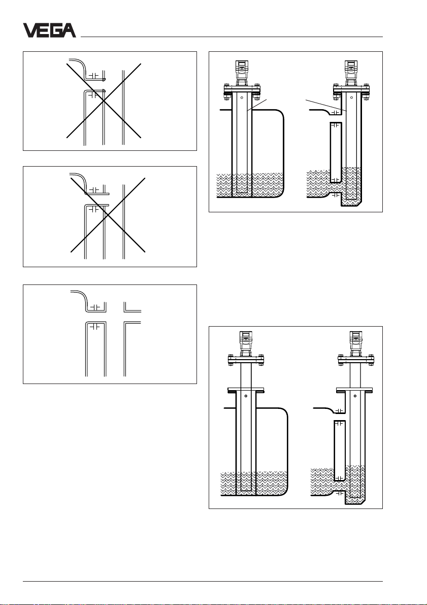
Welding beads too large
Tube connection protrudes
Mounting and installation
Conducting tube
Conducting tube in existing surge or bypass tube
To increase the min. distance, the conducting
tube can protrude out of the surge or bypass
tube. For this purpose, a plain flange can be
welded at the required position on the outside of the extended conducting tube. In
both cases, an adequate vent hole must be
provided.
Additional connection to the bypass tube in one plane
Use of conducting tubes
(VEGAPULS 44)
In case of very rough inner surfaces in existing bypass tubes (e.g. due to corrosion) or
in case of big connection openings as well as
bypass tubes with an inner diameter of more
than 100 mm, the use of a conducting tube in
the existing bypass tube is recommended.
This reduces the noise level and increases
reliability considerably. The flange of the
conducting tube can be easily mounted as a
sandwich flange between vessel and sensor
flange.
20 VEGAPULS 42, 44 and 45 – VBUS
Extended conducting tube
Page 21
Mounting and installation
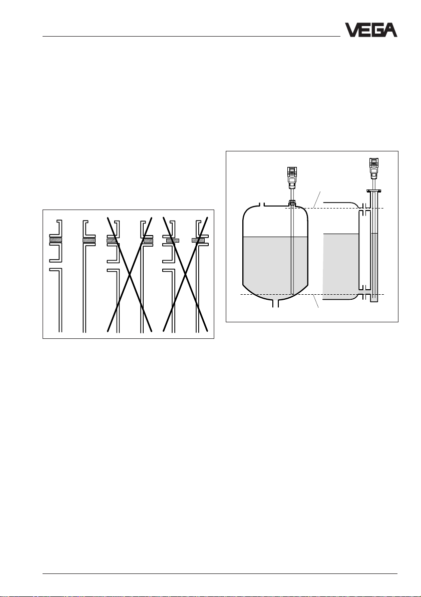
Seals on tube connections and tube extensions
Microwaves are very sensitive to gaps in
flange connections. If connections are made
without proper care, distinct false echoes as
well as increased signal noise can result.
Observe the following points:
• The seal used should correspond to the
tube inner diameter.
• If possible, conductive seals such as conductive PTFE or graphite should be used,
especially for thicker seals.
• Make sure that there are only a few seal
positions on a conducting tube.
Flange connections on bypass tubes
Adhesive products
For slightly adhesive products, choose a
surge pipe with e.g. a nominal width of
50 mm. VEGAPULS 42 and 44 radar sensors
with 26 GHz technology are relatively insensitive to buildup in the tube. Nevertheless,
buildup must not be allowed to plug up the
tube completely.
For adhesive products, the use of a DN 80 to
max. DN 100 stand/surge pipe can enable
measurement in spite of buildup. Products
that cause excessive buildup cannot be
measured in a standpipe.
VEGAPULS 45 with integrated measuring tube
The sensor version VEGAPULS 45 is especially developed for measuring tube applications and is supplied complete with a 27 mm
measuring tube. With a measuring tube
length up to 4 m, this sensor version is suitable e.g. for the use in existing standpipes.
max
min
VEGAPULS 45 with integrated measuring tube in a
free vessel or in an existing bypass pipe
Note:
VEGAPULS 45 sensors with integrated
measuring tube are equipped with a
threaded process fitting or a flange connection. For sensors with threaded process
fitting, make sure that the complete sensor,
i.e. also the sensor housing, turns when
screwing in. The sensor housing is fastened
with a clipped connection. This sensor housing must not be turned with respect to the
measuring tube or even loosened. Otherwise
the radar signal coupling would be
destroyed and the sensor would not function
proberly.
VEGAPULS 42, 44 and 45 – VBUS 21
Page 22
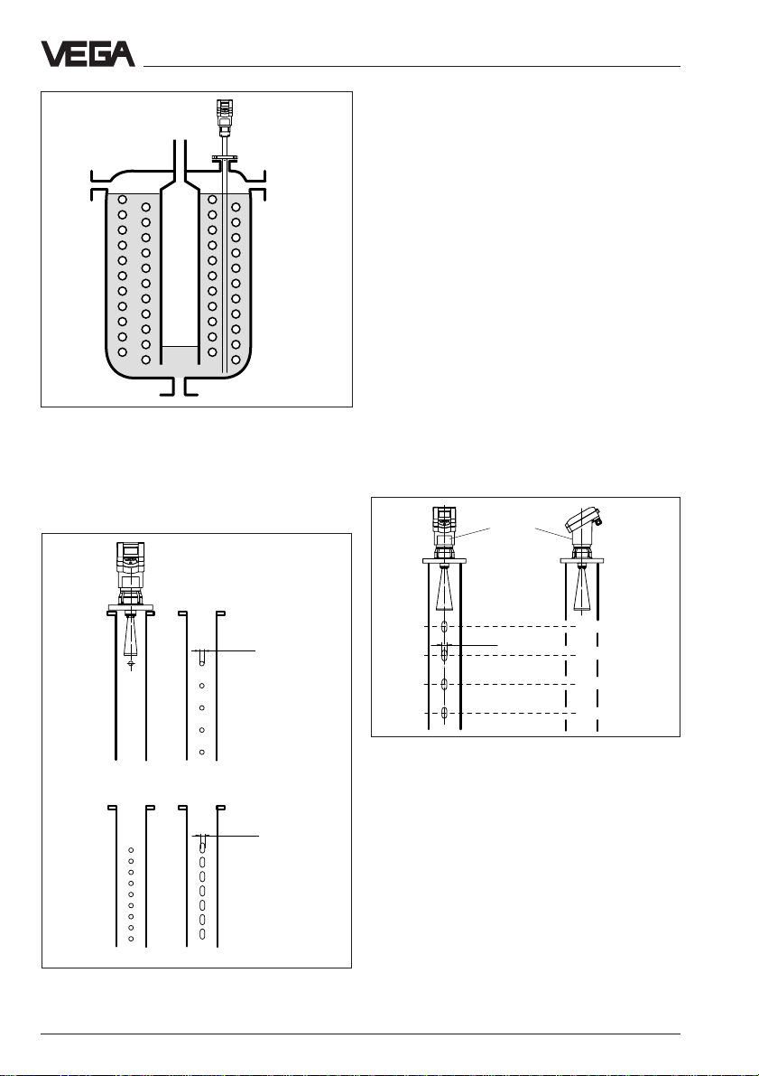
Mounting and installation
If you want to measure inhomogeneous products or stratified products in a surge pipe, it
must have holes, elongated holes or slots.
These openings ensure that the liquid is
mixed and corresponds to the liquid in the
vessel.
The more inhomogeneous the measured
product, the closer the openings should be
spaced.
Due to radar signal polarisation, the holes or
slots must be positioned in two rows offset
by 180°. The radar sensor must then be
mounted so that the type label of the sensor
is aligned with the rows of holes.
VEGAPULS 45 with integrated measuring tube (surge
pipe) measures between the heating spirals
Standpipe measurement of inhomogeneous products
ø 5...15
homogeneous
liquids
slightly inhomogeneous
liquids
ø 5...15
Every wider slot causes a false echo. The
slots should therefore not exceed a width of
10 mm, to keep the signal-to-noise ratio at a
minimum. Round slot ends are better than
rectangular ones.
Type label
ø 5...15
VEGAPULS 44: Rows of holes on one axis with the
type label
inhomogeneous liquids
Openings in a surge pipe for mixing of inhomogeneous products
22 VEGAPULS 42, 44 and 45 – VBUS
Page 23
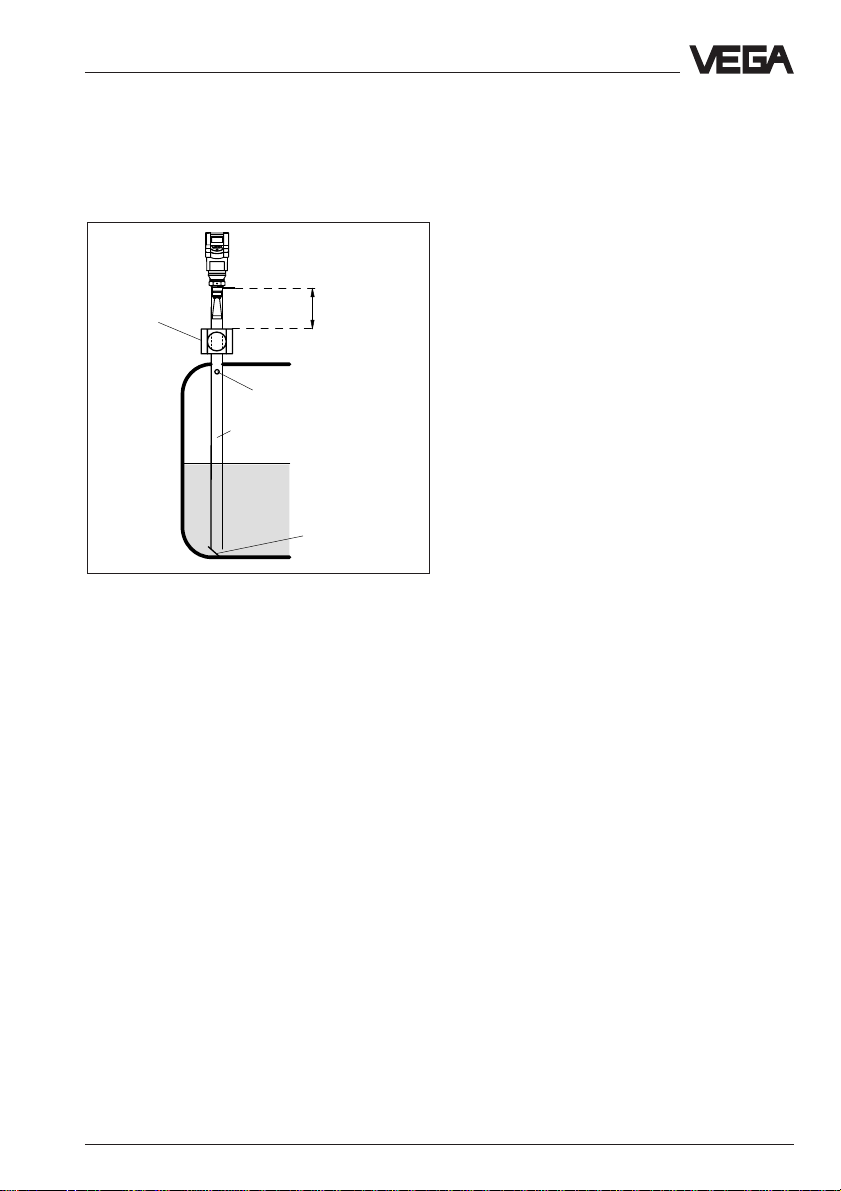
Mounting and installation
Surge pipe with ball valve
If a ball valve is mounted in the surge pipe,
maintenance and servicing can be carried
out without opening the vessel (e.g. if it contains liquid gas or toxic products).
Ball valve
ø50
Tube antenna system with ball valve cutoff in measuring tube
A prerequisite for trouble-free operation is a
ball valve throat that corresponds to the pipe
diameter and provides a flush surface with
the pipe inner wall. The valve must not have
any rough edges or constrictions in its channel and should have a min. distance of 300
mm from the sensor flange.
> 300 mm
Vent hole
Deflector
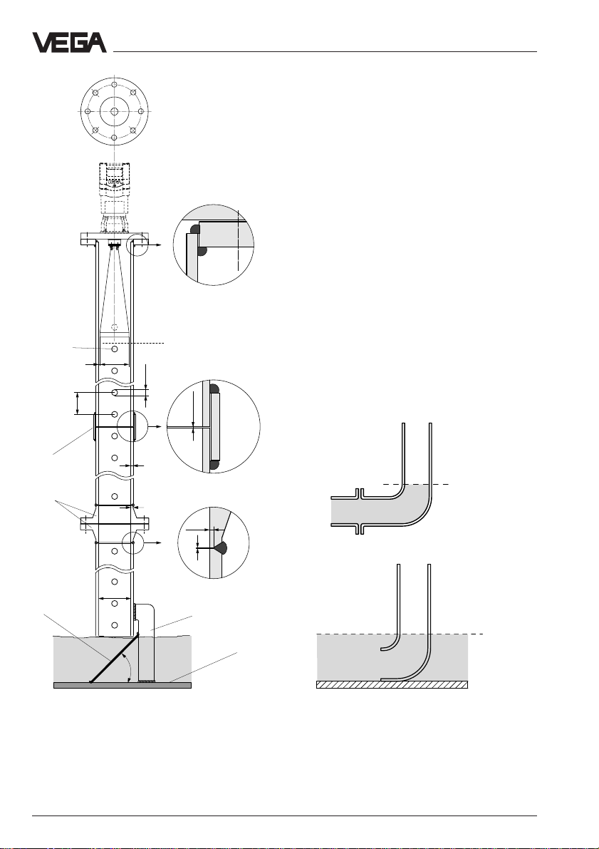
Guidelines for standpipe construction
Radar sensors for measurement on surge or
bypass pipes are used with G 1½ A
screwed-on antenna or flange sizes DN 50,
DN 80, DN 100 and DN 150. The radar
sensor with a DN 50 flange is only a
functional measuring system in conjunction
with a measuring tube.
On the left you see the constructional features of a measuring pipe (surge or bypass
tube) as exemplified by a sensor with DN 50
flange.
The measuring pipe must be smooth inside
(average surface quality Rz ≤ 30). Use stain-
less steel tubing (drawn or welded lengthwise) for construction of the measuring pipe.
Extend the measuring pipe to the required
length with welding neck flanges or with connecting sleeves. Make sure that no shoulders
or projections are created during welding.
Before welding, join pipe and flange with their
inner surfaces flush and exactly fitting.
Avoid welding through the pipe wall. The pipe
must remain smooth inside. Roughness or
welding beads on the inner surfaces must be
carefully removed and burnished, as they
cause false echoes and encourage product
adhesion.
On the following page you will see the
constructional features of a measuring pipe
as exemplified by a sensor with DN 100
flange.
If the vessel contains agitated products,
fasten the measuring pipe to the vessel bottom. Provide additional fastenings for longer
measuring pipes.
VEGAPULS 42, 44 and 45 – VBUS 23
Page 24
Mounting and installation
0 %
Flange
DN 100
Deburr the
holes
150…500
Connecting
sleeve
Welding neck
flanges
VEGAPULS 44
When measuring products with lower dielectric values (< 4), a part of the radar signal
penetrates the medium. If the vessel is nearly
empty, an echo is generated by the medium
and the vessel bottom. In some cases, the
vessel bottom generates a stronger signal
echo than the product surface. With a deflector on the measuring pipe end, the radar
signals are scattered. In nearly empty vessels and products with low dielectric value,
the medium then generates a stronger echo
than the vessel bottom.
Thanks to the deflector, only the useful signal
is received in a nearly empty vessel - the
Welding of the plain
welded flange
100 %
ø 95
2
Welding of the connecting sleeves
5…10
correct measured value is thus transmitted
and the 0 % level reliably detected.
Instead of a deflector, the standpipe or surge
pipe can be equipped with a quadrant pipe
at the end. This reflects the radar signals that
penetrate the medium diffusely to the side
and reduces strong echoes from the tube
0,0…0,4
3,6
Welding of the welding
neck flange
3,6
1,5…2
0,0…0,4
end or vessel bottom.
0 %
Quadrant pipe on the bypass tube end
Deflector
0 %
ø 100,8
~45˚
Meas. pipe fastening
Vessel
bottom
Quadrant pipe on the standpipe end
24 VEGAPULS 42, 44 and 45 – VBUS
Page 25
Mounting and installation
3.4 False echoes
The mounting location of the radar sensor
must be selected such that no installations or
inflowing material cross the radar impulses.
The following examples and instructions
show the most frequent measuring problems
and how to avoid them.
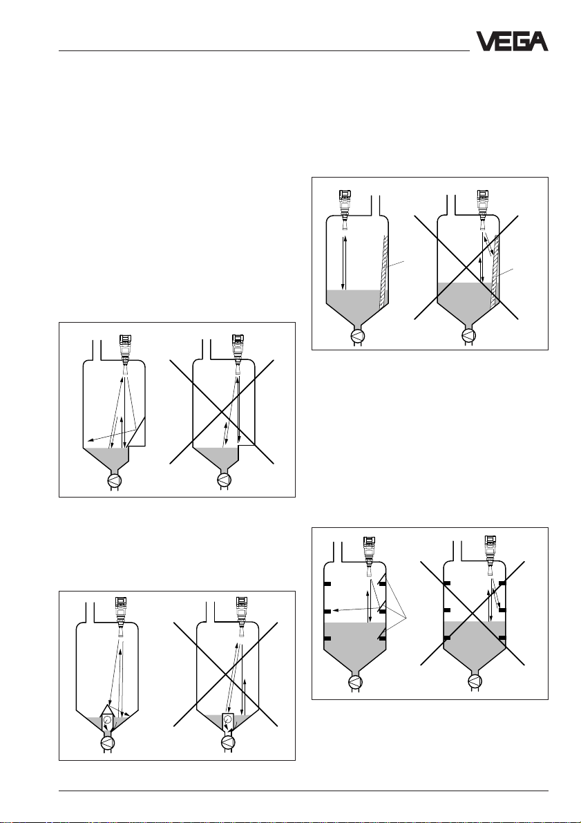
Vessel protrusions
Vessel forms with flat protrusions can, due to
their strong false echoes, greatly effect the
measurement. Shields above these flat protrusions scatter the false echoes and guarantee a reliable measurement.
Correct Wrong
Vessel protrusions (slope)
Intake pipes, i.e. for the mixing of materials with a flat surface directed towards the sensor - should be covered with a sloping shield
that will scatter false echoes.
Vessel installations
Vessel installations such as, for example, a
ladder, often cause false echoes. Make sure
when planning your measuring location that
the radar signals have free access to the
measured product.
Correct Wrong
Ladder
Vessel installations
Ladder
Struts
Struts, like other vessel installations, can
cause strong false echoes superimposed on
the useful echoes. Small shields effectively
hinder a direct false echo reflection. These
false echoes are scattered and diffused in
the area and are then filtered out as "echo
noise" by the measuring electronics.
Correct Wrong
Correct Wrong
Struts
Vessel protrusions (intake pipe)
VEGAPULS 42, 44 and 45 – VBUS 25
Shields
Page 26
Mounting and installation
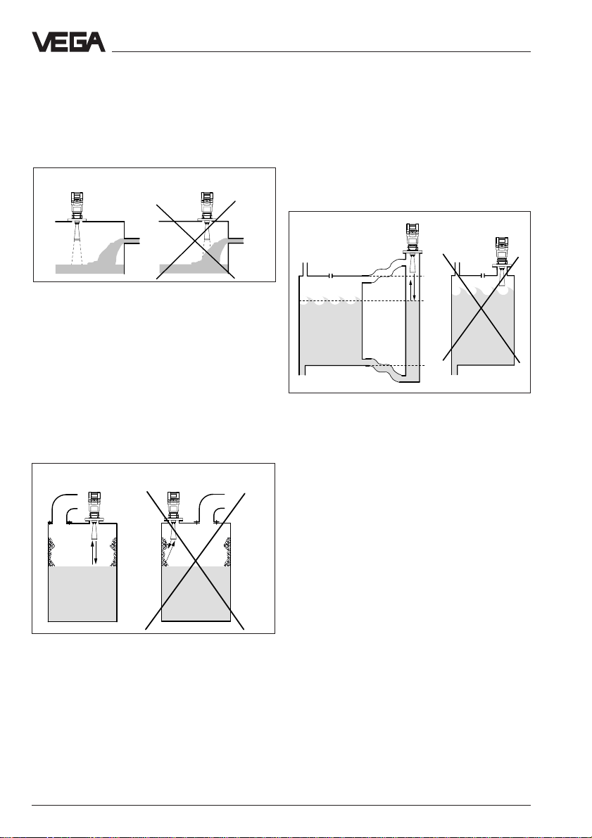
Inflowing material
Do not mount the instrument in or above the
filling stream. Ensure that you detect the
product surface and not the inflowing material.
Correct
Inflowing material
Wrong
Buildup
If the sensor is mounted too close to the
vessel wall, buildup and adhesions of the
measured product to the vessel wall will
cause false echoes. Position the sensor at a
sufficient distance from the vessel wall.
Please also note chapter "3.1 General installation instructions".
Correct Wrong
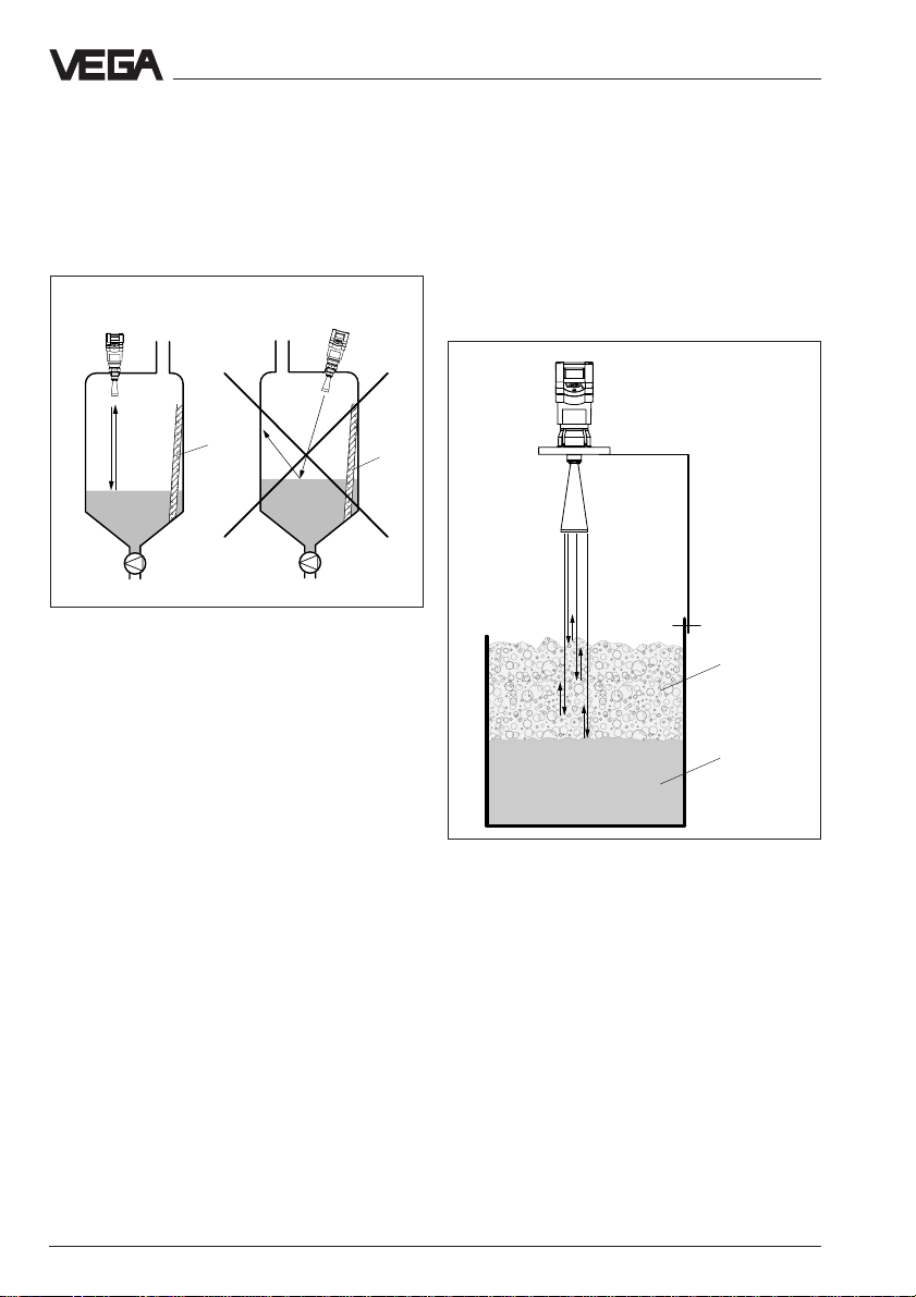
Strong product movements
Strong turbulences in the vessel, e.g. caused
by stirrers or strong chemical reactions, can
seriously interfere with the measurement. A
surge or bypass tube (figure) allows, provided the product causes no buildup in the
tube, a reliable measurement even with
turbulences in the vessel.
Correct Wrong
100 %
75 %
0 %
Strong product movements
Buildup
26 VEGAPULS 42, 44 and 45 – VBUS
Page 27
Mounting and installation
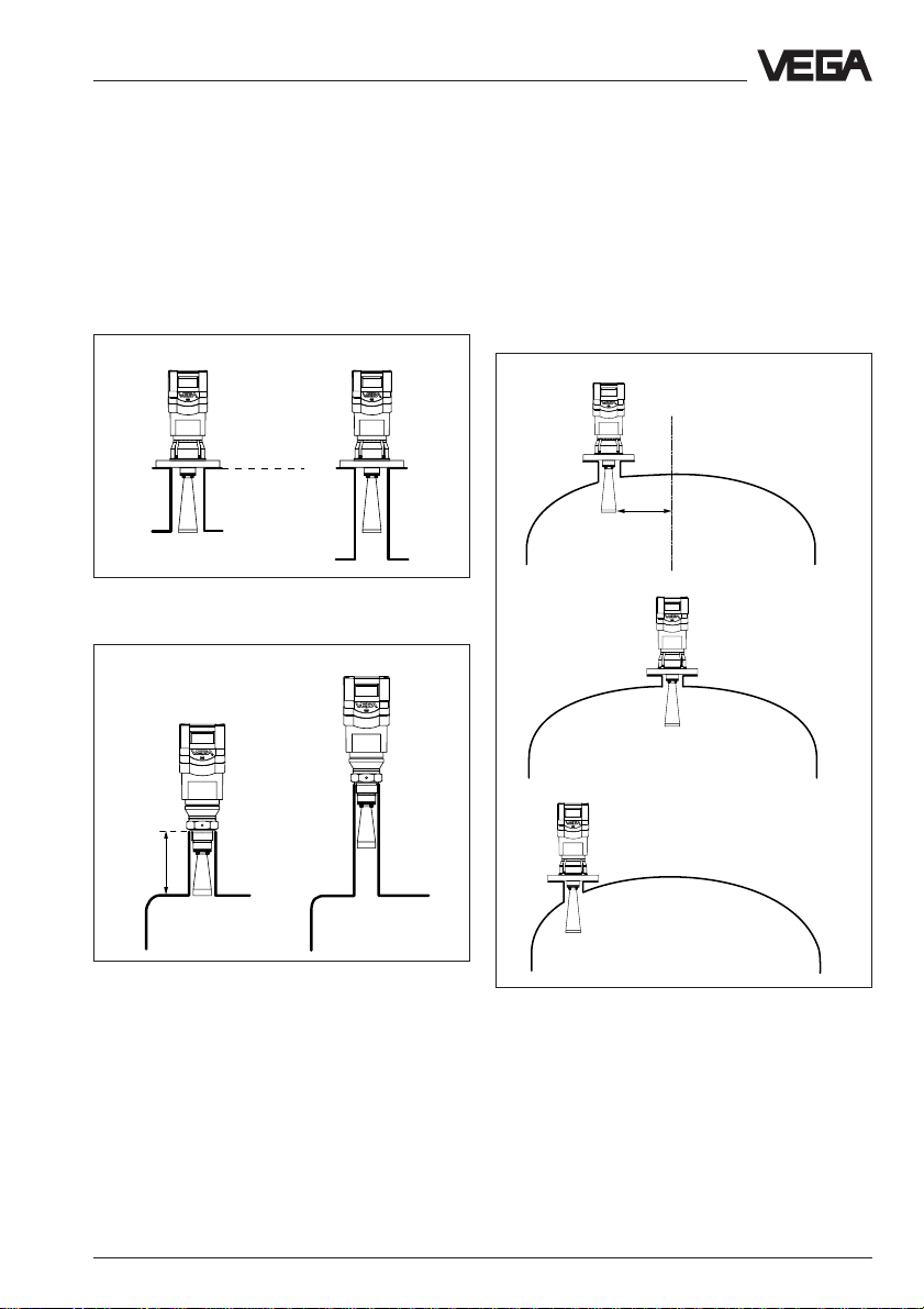
3.5 Installation mistakes
Socket piece too long
If the sensor is mounted in a socket extension that is too long, false reflections are
caused and measurement is hindered. Make
sure that the horn antenna protrudes out of
the socket piece.
Correct Unfavourable
Reference
plane
Flange antenna: Correct and unfavourable socket
length
Unfavourable
Correct
Parabolic effects on dished or arched
vessel tops
Round or parabolic tank tops act like a parabolic mirror on the radar signals. If the radar
sensor is placed at the focal point of such a
parabolic tank top, the sensor receives amplified false echoes. The optimum mounting
position is generally in the range of half the
vessel radius from the centre.
Correct
~ ½
vessel
radius
Unfavourable
Unfavourable
< 135 mm
(250 mm)
Screw-on antenna: Correct and unfavourable socket
length
VEGAPULS 42, 44 and 45 – VBUS 27
Mounting on a vessel with parabolic tank top
Page 28
Mounting and installation
Wrong orientation to the product
Weak measuring signals are caused if the
sensor is not directly pointed at the product
surface. Orient the sensor axis perpendicularly to the product surface to achieve reliable
measuring results.
Correct Wrong
Ladder
Direct sensor vertically to the product surface
Ladder
Sensor too close to the vessel wall
If the radar sensor is mounted too close to
the vessel wall, strong false echoes can be
caused. Buildup, rivets, screws or weld joints
superimpose their echoes onto the product
or useful echo. Please ensure sufficient distance from the sensor to the vessel wall.
Foam generation
Conductive foam is penetrated by the radar
signals to different depths and generates a
number of single (bubble) echoes. The signals in the foam are also damped, like heat
radiation that tries to penetrate styrofoam.
Thick, dense, creamy foam, and especially
conductive foam, on the product surface can
cause incorrect measurements.
conductive
foam
Liquid
In case of good reflection conditions (liquids
Foam generation
without vessel installations), we recommend
selecting the sensor distance so that there is
no vessel wall within the inner emission cone.
For products in less favourable reflection
environments, it is a good idea to also keep
the outer emission cone free of interfering
installations. Note chapter "3.1 General installation instructions".
Take measures to avoid foam, measure in a
bypass tube or use a different measuring
technology, e.g. capacitive electrodes or
hydrostatic pressure transmitters.
In many cases, VEGAPULS 54 radar sensors
with 5.8 GHz operating frequency achieve
considerably better and more reliable measuring results in foam applications than type
40 sensors with 26 GHz technology.
28 VEGAPULS 42, 44 and 45 – VBUS
Page 29

Mounting and installation
Installation mistakes in the standpipe
Pipe antenna without ventilation hole
Pipe antenna systems must be provided with
a ventilation hole on the upper end of the
surge pipe. The lack of a hole will cause false
measurements.
Correct
Pipe antenna: The surge pipe open to the bottom
must have a ventilation or equalisation hole on top
Wrong
Wrong polarisation direction
When measuring in a surge pipe, especially if
there are holes or slots for mixing in the tube,
it is important that the radar sensor is aligned
with the rows of holes.
The two rows of holes (displaced by 180°) of
the measuring tube must be in one plane with
the polarisation direction of the radar signals.
The polarisation direction is always in the
same plane as the type label.
Correct
VEGAPULS 44 on the surge pipe: The sensor type
plate must be aligned with the rows of holes.
Type label
Wrong
VEGAPULS 42, 44 and 45 – VBUS 29
Page 30

4 Electrical connection
Electrical connection
4.1 Connection and connection cable
Safety information
As a rule, do all connecting work in the complete absence of line voltage. Always switch
off the power supply before you carry out
connecting work on the radar sensors. Protect yourself and the instruments.
Qualified personnel
Instruments which are not operated with
protective low voltage or DC voltage must
only be connected by qualified personnel.
Connection and grounding
A standard two or four-wire cable (sensors
with separate supply) with max. 2.5 mm
be used for connection. The earth conductor
terminal is galvanically connected with the
process fitting (thread or flange).
Ex protection
If an instrument is used in hazardous areas,
the respective regulations, conformity certificates and type approvals for systems in Ex
areas must be noted (e.g. DIN 0165).
2
can
Note!
In Ex applications, grounding on both ends is
not allowed due to potential transfer. If an
instrument is used in hazardous areas, the
respective regulations, conformity certificates
and type approvals for systems in Ex areas
must be noted (e.g. DIN 0165).
Note the approval documents and the included safety data sheet attached to the Ex
sensors.
Connection cable
Please note that the connection cables are
specified for the expected operating conditions
in your systems. The cable must have an outer
diameter of 5 … 9 mm (1/2 to 1/3 inch). Otherwise the seal effect of the cable entry will not be
ensured.
Cables for intrinsically safe circuits must be
marked blue and must not be used for other
circuits.
Intrinsically safe circuits with more than one
active instrument (instrument delivering electrical energy) are not allowed. Please note the
special installation regulations (DIN 0165).
30 VEGAPULS 42, 44 and 45 – VBUS
Page 31

Electrical connection
Screening of the sensor cable
currents flow through the cable screening.
Ground equalisation currents can be avoided
Very often, the "electromagnetic pollution"
caused by electronic actuators, energy
cables and transmitting stations is so
considerable that the sensor cable must be
screened.
by ground potential equalisation systems.
When earthing on both ends, it is possible to
connect the cable shield on one earth side
(e.g. in the switching cabinet) via a capacitor
(e.g. 10 nF; 1500 V) to the earth potential.
Use a very low-resistance earth connection
We recommend the use of screening to avoid
(foundation, plate or mains earth).
future interferences. However, you must
make sure that no ground equalisation
Screening magnetic low-frequency high-frequency ground currents
fields electrical electrical and superimposed
fields fields potential currents
l < ––
λ
7
l > ––
λ
7
none – – – –
one side – ++ – –
two sides + + ++ ++
++ good protection against electromagnetic pollution
+ protection against electromagnetic pollution
– no protection against electromagnetic pollution
Note: λ (Lambda) =– – –
c
f
l cable length
c light velocity (300000 km/s)
f interfering frequency
λ wavelength
Example: Interfering frequency approx. 100 kHz
m
1c 13 • 10
l < – • – = – • ––––––––– = 4285 m
7 f 7 100 • 10
9
–
s
1
3
–
s
This means that interference can be avoided by earthing on both ends (better on one end) in
case of an interfering frequency of 100 kHz up to a cable length of approx. 4000 m.
Earthing on the sensor end
Earthing on both ends (on the signal
conditioning instrument via the potential
separation capacitor)
e.g. 10 nF,
1500 V AC
VEGAMET
515V
VEGAPULS 42, 44 and 45 – VBUS 31
VEGAMET
515V
Page 32

Electrical connection
Linear (serial) arrangement of sensors
Grounding of the cable screen on both ends, at the end of each sensor arry via a ground capacitor.
CPU
VEGALOG
VEGALOG
VEGALOG
VEGALOG
571 CPU
571 EV
571 EV
571 EV
2
2
Radial arrangement of sensors
Grounding on at least two ends, on VEGALOG and once on the sensor star, i.e. on the longest
sensor line. If the individual sensor lines are longer than approx. 15 m, a grounding of each
longer line should be made via a ground capacitor.
CPU
VEGALOG
VEGALOG
VEGALOG
VEGALOG
571 CPU
571 EV
571 EV
571 EV
2
4
2
2
2
4
2
2
32 VEGAPULS 42, 44 and 45 – VBUS
Page 33

Electrical connection
4.2 Connection of the sensor
After mounting the sensor at the measurement location according to the instructions in
chapter "3 Mounting and installation", loosen
the closing screw on top of the sensor. The
sensor lid with the optional indication display
can then be opened. Unscrew the sleeve nut
and slip it over the connection cable (after
removing about 10 cm of insulation). The
sleeve nut of the cable entry has a self-locking ratchet that prevents it from opening on
its own.
Version with plastic housing
Power supply and BUS
signal
+-
To the indicating instrument in the
sensor lid or the external VEGADIS 50
indicating instrument
Terminals
(max. 2.5 mm
wire cross-section)
2
Now insert the cable through the cable entry
into the sensor. Screw the sleeve nut back
onto the cable entry and clamp the stripped
wires of the cable into the proper terminal
positions.
The spring terminals hold the wire without a
screw. Press the white opening tabs with a
small screwdriver and insert the copper core
of the connection cable into the terminal
opening. Check the hold of the individual
wires in the terminals by lightly pulling on
them.
Version with Aluminium housing
Power supply and BUS
signal
+
To the indicating instrument in the
-
sensor lid or the external VEGADIS 50
indicating instrument
M20 x 1.5
(diameter of the
connection cable
5…9 mm)
-+
2
1
VBUS
Tank 1
m (d)
12.345
Communication
5678
Display
2.23273
ESC
+
-
OK
+ 1
VBUS
2 -
Tank 1
m (d)
12.345
Communication
5678
Display
2.23273
ESC
+
-
OK
VEGAPULS 42, 44 and 45 – VBUS 33
Page 34

Electrical connection
4.3 Connection of the external indicating instrument VEGADIS 50
OUTPUT
(to the sensor)
SENSOR
DISPLAY
(in the cover of the indicating instrument)
DISPLAY1234 56 78
Loosen the four screws of the housing cover
on VEGADIS 50.
The connection procedure can be facilitated
by fixing the housing cover during connection work with one or two screws on the right
of the housing.
Power supply and BUS
signal
+
-
1
Communication
(+) L12N
Tank 1
m (d)
12.345
VEGADIS 50
Adjustment
module
ESC
+
-
Tank 1
m (d)
12.345
5678
Display
2.23274
ESC
+
-
OK
OK
Screws
34 VEGAPULS 42, 44 and 45 – VBUS
Page 35

Electrical connection
4.4 Configuration of measuring systems
A measuring system consists of one sensor
and one processing unit. The processing unit
(VEGAMET signal conditioning instrument or
VEGALOG processing system) evaluates the
level-proportional, digital measuring signals
in a number of processing routines and outputs the levels as individual current, voltage
or switching signals.
Two sensors can be connected via one twowire cable to VEGAMET signal conditioning
instrument. Up to 255 sensors can be connected to the VEGALOG 571 processing
system. 15 sensors (loop powered) can be
connected on one two-wire cable.
Beside the output of the level in percent,
cubic meter or other physical units, as current, voltage or switching signal (relay or
transistor), the levels can also be processed
by linked processing algorithms. Scaling,
linearisation, calculation of linearisation
curves, differential generation, addition or
tendency processing are an integral part of
the VEGALOG processing systems and
VEGAMET and are easy to implement via the
menu selection.
Ex
Series 40 sensors with VBUS signal require
for operation in Ex areas the Ex separator
VEGATRENN 548V Ex, providing intrinsically
safe Ex circuits to the sensors. Up to nine
sensors (in groups of three sensors) can be
connected to the Ex separator VEGATRENN
548V Ex.
Connection cable
Sensor wiring should be looped in screened
cables. Ground the cable screens on the
processing system, or better, on the sensor.
We recommend grounding the cable screens
on both ends. However, make sure that no
earth compensation currents flow via the
screens. When earthing on both ends, it is
possible to connect the cable shield on one
earth side (e.g. in the switching cabinet) via a
capacitor (e.g. 10 nF; 1500 V).
On the following page you will see the various
instrument configurations (measuring systems) consisting of sensor(s) and processing unit.
VEGAPULS 42, 44 and 45 – VBUS 35
Page 36

Electrical connection
1 … 2 sensors on the VEGAMET 515V signal conditioning instrument
• Two-wire technology, power supply from the signal conditioning instrument, output signals
and power supply via one two-wire cable.
• Digital output signal, two sensors on one cable.
• Display of measured value in the sensor and in the signal conditioning instrument.
• Optional external indicating instrument (can be mounted up to 25 m away from the sensor in
Ex area).
• Adjustment with PC, signal conditioning instrument or adjustment module MINICOM (can be
plugged into the sensor or into the external indicating instrument VEGADIS 50).
• Max. resistance of the signal cable 15 Ω per wire, max. 1000 m cable length.
VEGADIS 50
4
4
1)
Sensor wiring should be looped in screened cables.
2
VEGACONNECT 2
In case of high frequency interference (> 1 MHz),
it is best to ground the cable screens on both
ends. Please make sure that no earth
compensation currents flow via the screens.
You avoid earth compensation currents (when
grounding at both ends) by connecting the cable
screen on one end (e.g. in the switching cabinet)
via a capacitor (e.g. 10 nF; 1500 V) with the
ground potential.
In case of electromagnetic interferences, screened cable should be
used (see following page)
2
Processings see also Product
Information "Signal conditioning
instruments series 500"
Current outputs
2
VEGAMET
515V
VEGAMET 515V signal conditioning instrument in housing type
505
Voltage outputs
Relays
Digital wiring
Fault signals
36 VEGAPULS 42, 44 and 45 – VBUS
Page 37

Electrical connection
1 … 2 sensors in Ex environment via separator VEGATRENN
"ia"
548V Ex on the VEGAMET 515V signal conditioning instrument
• Two-wire technology, power supply via separator, output signals and power supply via one
two-wire cable.
• Ex environment acc. to CENELEC and ATEX.
• Digital output signal, two sensors on one cable.
• Display of measured values in the sensor and in the signal conditioning instrument.
• Optional external indicating instrument (can be mounted up to 25 m away from the sensor
also in Ex area).
• Adjustment with PC, signal conditioning instrument or adjustment module MINICOM (can be
plugged into the sensor or into the external indicating instrument VEGADIS 50).
• Max. resistance of the signal cable 15 Ω per wire, max. 1000 m cable length (see also approval certificates of the separators).
VEGADIS 50
4
Zone 0
or
Zone 1
4
Zone 0
or
Zone 1
1)
Sensor wiring should be looped in screened cables.
Ex area Non-Ex area
EEx ia
2
In case of high frequency interference (> 1 MHz),
it is best to ground the cable screens on both
ends. Please make sure that no earth
compensation currents flow via the screens.
You avoid earth compensation currents (when
grounding at both ends) by connecting the cable
screen on one end (e.g. in the switching cabinet)
via a capacitor (e.g. 10 nF; 1500 V) with the
ground potential.
In case of electromagnetic
interferences, screened cable
should be used (see following
VEGAMET
page)
Processings see also Product
Information "Signal conditioning
instruments series 500"
VEGATRENN
548V
515V
2
2
VEGACONNECT 2
VEGAMET 515V signal conditioning instrument with Ex separator VEGATRENN 548V Ex
in housing type 506
Note!
In Ex systems, earthing on both ends is not
allowed due to potential difference. It is allowed, however in conjunction with potential
equalisation system or y
capacitors.
c
Current outputs
Voltage outputs
Relays
Digital wiring
Fault signals
VEGAPULS 42, 44 and 45 – VBUS 37
Page 38

Electrical connection
5 sensors per two-wire cable (grouped radially) on the VEGALOG 571 processing
system
• 15 sensors with power supply and digital output signals via three two-wire cables on one
input card of the VEGALOG 571 processing system.
• Display of measured values integrated in the sensor.
• Optional external indicating instrument (can be mounted up to 25 m away from the sensor in
Ex area).
• Adjustment with PC or adjustment module MINICOM (can be plugged into the sensor or into
the external indicating instrument VEGADIS 50).
• Max. resistance of the signal cable 15 Ω per wire, max. 1000 m cable length.
2
2
4
2
2
4
2
4
CPU
VEGALOG
VEGALOG
VEGALOG
VEGALOG
571 CPU
571 EV
571 EV
571 EV
2
2
38 VEGAPULS 42, 44 and 45 – VBUS
Page 39

Electrical connection
5 sensors per two- wire cable (grouped in line) on the VEGALOG 571 processing
system
• 15 sensors with power supply and digital output signals via three two-wire cables on one
input card of the VEGALOG 571 processing system.
• Display of measured values integrated in the sensor.
• Optional external indicating instrument (can be mounted up to 25 m away from the sensor
also in Ex area).
• Adjustment with PC or adjustment module MINICOM (can be plugged into the sensor or into
the external indicating instrument VEGADIS 50).
• Max. resistance of the signal cable 15 Ω per wire, max. 1000 m cable length.
2
2
2
CPU
VEGALOG
VEGALOG
571 CPU
571 EV
2
VEGAPULS 42, 44 and 45 – VBUS 39
Page 40

Electrical connection
15 sensors via one two-wire cable on the VEGALOG 571 processing system
• 15 sensors with power supply and digital output signals via one two-wire cable on one input
card of the VEGALOG 571 processing system.
• Display of measured values integrated in the sensor.
• Optional external indicating instrument (can be mounted up to 25 m away from the sensor
also in Ex area).
• Adjustment with PC or adjustment module MINICOM (can be plugged into the sensor or into
the external indicating instrument VEGADIS 50).
• Max. resistance of the signal cable with 15 sensors on one two-wire cable 10 Ω per wire
(instead of 15 Ω), max. 1000 m cable length.
VEGADIS 50
4
VEGADIS 50
4
VEGADIS 50
4
Screened cable in case of electromagnetic interferences
2
2
2
1)
Processings see also Product
Information "Signal conditioning instruments series 500"
Current outputs
2
CPU
Voltage output
Relay outputs
Transistor output
Fault signals
Display outputs
Digital wiring
Connection to all
bus systems
2
2
VEGACONNECT 2
2
VEGALOG
VEGALOG
571 CPU
571 EV
VEGALOG 571 processing system
with input cards in 19" rack. 15
sensors on one module card and
cable
Interface cable RS 232
1)
Sensor wiring should be looped in screened
cables. Please make sure that no earth
compensation currents flow via the screens.
You avoid earth compensation currents (when
grounding at both ends) by connecting the cable
screen on one end (e.g. in the switching cabinet)
via a capacitor (e.g. 10 nF; 1500 V) with the
ground potential.
15 sensors per two-wire cable
individual grouping
40 VEGAPULS 42, 44 and 45 – VBUS
Page 41

Electrical connection
5 sensors per two-wire cable via VEGATRENN 548V Ex separator
"ia"
on the VEGALOG 571 processing system
• 5 sensors with power supply and digital output signals via one two-wire cable on the separator.
• Display of measured values integrated in the sensor.
• Optional external indicating instrument (can be mounted up to 25 m away from the sensor
also in Ex area).
• Adjustment with PC or adjustment module MINICOM (can be plugged into the sensor or into
the external indicating instrument VEGADIS 50).
• Max. resistance of the signal cable 15 Ω per wire, max. 1000 m cable length (see also approval certificates of the separators and technical data).
VEGADIS 50
2
Ex area
EEx ia
Non-Ex area
EEx ia
2
2
Screened cable in case of electromagnetic
interferences
CPU
1)
2
2
2
2
2
2
2
2
2
Processings see also
Product Information
"Signal conditioning
instruments series
500". Current outputs
etc. like image on
previous page
2
2
2
VEGALOG
VEGALOG
VEGATRENN
571 CPU
571 EV
548
VEGALOG 571
processing system
(19" module card)
VEGATRENN
VEGATRENN
VEGALOG
VEGATRENN
VEGATRENN
571 EV
548
548
548
548
Input card of
VEGALOG 571
VEGATRENN 548V Ex
separator (max. 15
sensors per card)
Input card of VEGALOG 571 (max. 15
sensors per card)
VEGACONNECT 2
2
2
1)
Sensor wiring should be looped in screened cables. In case of high frequency
Interface cable RS 232
interference (> 1 MHz) it is best to ground the cable screens on both ends.
Please make sure that no earth compensation currents flow via the screens.
You avoid earth compensation currents (when grounding at both ends) by
connecting the cable screen on one end (e.g. in the switching cabinet) via a
capacitor (e.g. 10 nF; 1500 V) with the ground potential. Sensor cables
leading to the same separator card can be looped together in one screened
5 sensors per two-wire cable
individual grouping
multiwire cable. Sensor cables leading to other separator cards must be
looped in separate screened cables.
VEGAPULS 42, 44 and 45 – VBUS 41
Page 42

5 Setup
Setup
5.1 Adjustment structure
The radar sensors can be operated
- with the PC (adjustment program VVO,
version ≥ 2.70)
- with the adjustment module MINICOM
- with the VEGAMET signal conditioning
instrument.
The adjustment is always possible with one
adjustment instrument at once.
Adjustment with the PC
The PC with the adjustment program VVO
(VEGA Visual Operating) in version ≥ 2.70
can be connected to:
- the sensor
- the signal cable
- the VEGAMET 514V, 515V signal conditioning instrument
- the VEGALOG 571 processing system.
With the adjustment program VVO on the PC,
you can adjust the radar sensors very easily.
A digital adjustment signal is herewith
superimposed to the signal and supply
cable. By this means, the adjustment can be
made directly on the sensor, on any position
of the signal cable or on the VEGAMET or
VEGALOG processing system.
Note:
Make sure that for adjustment of VEGAPULS
42, 44 and 45 sensors, the adjustment program VVO in version 2.70 or higher is
installed.
PC directly on the sensor
Insert VEGACONNECT into the communication sockets of an individual sensor. Only
sensor-relevant adjustment options such as
e.g., sensor optimisation on the affected
sensor, are adjustable. Other sensors and
VEGAMET are then not adjustable. This is
due to an adjustment hierarchy beginning
with VEGAMET or VEGALOG and ending
with the sensor.
PC on the signal cable
Only the sensor-relevant adjustment options
of sensors connected to the signal cable are
adjustable on the signal cable. However, not
available are the configuration and measured
data processing functions of VEGAMET or
VEGALOG.
Note:
The adjustment with the "PC on the signal
cable" and with the "PC directly on the sensor" is described in chapter "5.2 Adjustment
with the PC on the signal conditioning instrument". For this reason, adjustment with the
PC when connected directly to the sensor or
the signal cable is not shown separately.
Adjustment with the PC on the VEGAMET
signal conditioning instrument or on the
VEGALOG processing system
The PC communicates via the interface converter VEGACONNECT 2 with the signal
conditioning instrument or via the standard
RS 232 interface cable with the VEGALOG
processing system and all sensors connected to VEGAMET or VEGALOG. If you
connect the PC to the processing system or
the signal conditioning instrument, besides
the connected sensors, also the processing
system or the signal conditioning instrument
is adjustable.
Adjustment with the VEGAMET signal
conditioning instrument
Sensor and VEGAMET signal conditioning
instrument can be operated with the 6 key
adjustment field of the signal conditioning
instrument just like with the adjustment program VVO. The scope of the adjustment
functions is the same as with VVO on the PC.
42 VEGAPULS 42, 44 and 45 – VBUS
Page 43

Setup
Adjustment with the adjustment module
MINICOM
With the adjustment module MINICOM you
adjust the individual sensor directly in the
sensor or in the external indicating instrument
VEGADIS 50. The adjustment module
MINICOM with the 6 key adjustment field with
text display enables the parameter adjustment of the sensor with an array of functions
comparable to the adjustment program VVO
or the VEGAMET signal conditioning instrument, but not the configuration of the measuring system.
Adjustment of the signal conditioning instrument is only possible with the adjustment
program VVO or the 6 key adjustment field
on the instrument itself.
5.2 Adjustment with the PC on the signal conditioning instrument
To connect the PC to the signal conditioning
instrument, the interface converter
VEGACONNECT is required. The PC communicates via the interface converter with the
signal conditioning instrument and the connected sensors.
In the following setup and adjustment instructions you will find information on the following
topics and adjustment points:
•
Configuration
- create/modify measurement loop
- configuration info
•
Parameter adjustment 1
- adjustment
- conditioning/scaling
- meas. loop data
•
Sensor optimisation
- meas. environment/operating range
- meas. environment/meas. conditioning
- meas. environment/pulse velocity
- echo curve
- false echo storage
•
Parameter adjustment 2
- user-programmable linearisation curve
- linearisation curve
- defining the linearisation curve by incremental filling
- calculating the linearisation curve
- calculate cylindrical tank
•
Outputs
- configuration outputs
- parameter adjustment outputs
•
Display of measured value
•
Simulation
•
Backup
(optional)
Note:
Keep in mind that you first have to log in a
sensor in the configuration menu before you
can continue with the parameter setting and,
if necessary, carry out adjustments in the
menu "
Sensor optimisation
VEGAPULS 42, 44 and 45 – VBUS 43
".
Page 44

Adjustment with the PC on the signal conditioning instrument
Beside the measured values, adjustment
signals are also transmitted digitally via the
signal and supply cable between sensor and
VEGAMET. The adjustment program VVO
can then communicate with VEGAMET and all
connected sensors. In chapter "4.4 Configuration of measuring systems", connection of
the PC to different sensor arrangements is
shown.
Before starting setup:
Do not be confused by the many pictures,
adjustment steps and menus on the following
pages. Just carry out the setup with the PC
step by step and you will soon no longer
need the following instructions. Actions, like
entering a value or making a choice, are
indicated in the following by a large black
dot, like this:
• Choose …
• Start …
• Click to …
• Connect the standard output of your PC by
the standard RS 232 interlink cable to
VEGALOG.
• Now switch on the power supply of the
processing system.
By this convention, the actions to be carried
out are clearly separated from supplementary information in the following adjustment
instructions.
Start now:
• Connect the standard plug of
VEGACONNECT 2 (9-pole) to the interface
COM 1 or COM 2 of your PC.
• Insert the two small pin plugs of
VEGACONNECT 2 into the CONNECT
socket on the front of the signal conditioning instrument.
• Now switch on the power supply of the
signal conditioning instrument.
Usually after approx. 1 … 2 minutes (selftest) the measuring system is operating and
displaying the measured value.
• Now start the adjustment software VVO on
your PC.
• Choose with the arrow keys or the mouse
the item "
Planning
" and click to "OK".
You are asked for user identification.
• Enter under name "VEGA".
• Also enter "VEGA" under password.
You are asked for the kind of sensor connection or if you want to carry out a virtual
adjustment.
• Choose "
Direct cable connection
", if your
PC is directly connected to the VEGAMET
via a VEGACONNECT.
44 VEGAPULS 42, 44 and 45 – VBUS
Page 45

Adjustment with the PC on the signal conditioning instrument
The adjustment program VEGA Visual Operating (VVO), called in the following VVO, gets
into contact with the connected sensor or
processing system …
• Click to "OK" and you are in the main menu
window.
… and indicates after a few seconds if and
with which system a connection exists.
Note:
If you make no connection with the sensor,
check the following:
- Is the sensor being supplied with sufficient
voltage (min. 20 V)?
- Did you inadvertently use a
VEGACONNECT instead of the new
VEGACONNECT 2?
User identification
The preset user identification can be modified
later in the menu "
User access
".
If the adjustment software VVO gets in contact with the signal conditioning instrument for
the first time, you will be asked if you want to
transfer the data from the signal conditioning
instrument to the PC.
• Click to "
In the following menu window "
choice
Yes
".
DISBUS-group
" you can give a name to the database
or keep the proposed file name.
VEGAPULS 42, 44 and 45 – VBUS 45
Page 46

Adjustment with the PC on the signal conditioning instrument
Change COM port
In the menu "
nication
Configuration/Program/Commu-
" you can set the interface parameters
of your PC or change the used COM port.
Configuration
During the setup of the measuring system
you are confronted with two terms: "Configuration" and "Parameter adjustment". The
meas. system is first set up with a configuration and then with a parameter adjustment.
Note:
The signal conditioning instruments are
shipped with the sensor configuration you
ordered with the signal conditioning instrument.
Generally, you will use a preconfigured signal
conditioning instrument. In the following menu
"
Configuration
ments necessary and you can continue directly with the menu "
If your signal conditioning instruments are not
preconfigured, start now with the section
"
Configuration
adjustments in section "
ment
".
", there are normally no adjust-
Parameter adjustment
" and then continue with the
Parameter adjust-
".
No matter whether you set up a measuring
system (consisting of sensor and VEGAMET
signal conditioning instrument or VEGALOG
processing system) with the adjustment
software VVO or with the signal conditioning
instrument, the adjustment procedure is
always the same:
- first of all in the menu "
Configuration
", you
create a measurement loop
- then configure a measurement loop
- in the menu "
Instrument data
" you carry out
the parameter adjustment of the sensor.
Configuration
The term "Configuration" means the basic
adjustments of VEGAMET. You inform
VEGAMET about the application (level measurement, gauge, distance …), the measurement loop name and the input channel. The
configuration represents an electronic wiring
and labelling of your VEGAMET or, in other
words, telling the system which sensor for
what application and where.
Parameter adjustment
After the configuration, you carry out the
parameter adjustment for each individual
sensor. This means adjusting the sensors to
the respective operating range and adapting
them to the specific application. You infor m
the sensor which product distance (which
level) is "empty" and which "full". This is called
adjustment. Here you choose which physical
quantity (volume, mass) and unit of
measurement (m
3
, gal, liters …) the adjusted
measured value should be outputted in. In
the submenu "Sensor optimisation", you
inform the sensor electronics about the actual
environment, such as e.g. quick changes of
the measured value, foam generation, gas
stratification, solid or liquid.
46 VEGAPULS 42, 44 and 45 – VBUS
Page 47

Adjustment with the PC on the signal conditioning instrument
Create new measurement loop
• Choose the menu "Configuration/Measure-
ment loop/New" and you are in the menu
window "
Application
Create new measurement loop -
".
• Choose one of the two inputs of the
VEGAMET signal conditioning instrument
(VEGAMET 514V has only one sensor
input) and click to "OK".
• Choose the parameter (
ment"
, gauge or distance) and the sensor
type (
"Radar"
• Click to "
for radar).
Continue
".
"level measure-
After a few seconds, the menu window "
Create new measurement loop - Sensor configuration
" opens.
• Click in the menu window "
measurement loop - Sensor configuration
to "
Sensor coordination
"
Sensor coordination
• Click to "
• Then click to "
Sensor search
Input
Create new
"
". The menu window
" opens.
".
".
• Choose "
"
• Click to "
"
loop
VEGAPULS 42, 44 and 45 – VBUS 47
Standard level measurement
no options
".
Continue
" and the menu window
New application - Select measurement
" opens.
" and
• Choose the serial number of the sensor to
which you want to allocate e.g. input 1. If
two radar sensors are connected to
VEGAMET, you will get here a choice of the
serial numbers of the two sensors.
Page 48

Adjustment with the PC on the signal conditioning instrument
• Confirm with "OK".
• Click in the menu window "
nation
" again to "OK".
You are again in the menu window "
Sensor coordi-
Create
new measurement loop - Sensor configuration
".
• Click to "
Continue
"…
• Enter in the menu window "
Create new
measurement loop - Measurement loop
description
and a measurement loop description.
In this menu window you can select how your
level signal will be outputted, e.g. as current,
voltage, relay signal, etc. This "Configuration"
of outputs is described in detail in chapter
"Parameter adjustment 2" under "Outputs".
• Confirm with "OK" and the previous menu
window appears again. Click again to "OK"
and wait a moment until the settings are
transferred.
Configuration information
In the menu "
tem
" - "
configuration.
" a measurement loop number
Configuration/Measuring sys-
Sensor survey
" you can check the
• Click in the menu window "
Create new
measurement loop - Measurement loop
description
48 VEGAPULS 42, 44 and 45 – VBUS
" to "
Level
".
Page 49

Adjustment with the PC on the signal conditioning instrument
Parameter adjustment 1
In the menu "
justment
adjustments.
Adjustment
• Choose the menu "
meter adjustment
want to adjust.
If you have only configured one sensor on
the signal conditioning instrument, you will of
course have a choice of only one sensor.
Instrument data/Parameter ad-
" you carry out all important sensor
Instrument data/Para-
" and then the sensor you
You can carry out the min./max. adjustment
"with medium"
actual level) or
taking the actual level into consideration, i.e.
with empty vessel).
Generally, you will carr y out the adjustment
without medium, inasmuch as you need not
be concerned about the actual vessel filling
during adjustment. If you want to carry out
the adjustment with medium, you have to
carry out the min. adjustment with emptied
(also partly emptied) vessel and the max.
adjustment with filled (also partly filled) vessel. Carrying out the adjustment without medium is more convenient and quicker, as
shown in the example.
• Choose "
• Choose if you want the carry out the adjustment in
• Enter a distance for the upper and lower
level and the volume in % corresponding to
each distance.
(adjustment by means of the
"without medium"
no (adjustment without medium)
meters
(m) or in
(without
feet
(ft).
".
In the opening menu window, you now see
the previously entered measurement loop
names and the measurement loop descriptions.
• First choose "Adjustment".
• Click in the menu window "
"
Min/Max adjustment".
VEGAPULS 42, 44 and 45 – VBUS 49
Adjustment
" to
Page 50

Adjustment with the PC on the signal conditioning instrument
In the example, the 0 % filling is at a product
distance of 5.85 m and the 100 % filling at a
product distance of 1.27 m.
Note:
The sensor can only detect levels within the
defined operating range. To enable detection
of levels outside the operating range, it is
necessary to correct the operating range in
the menu "
ment
• Confirm your adjustments with "OK" and
you are again in the menu window "
ment
• Click in the menu window "
"
You are again in the menu window "
ment data parameter adjustment
Sensor optimisation/Meas. environ-
".
".
Quit
".
Adjust-
Adjustment
Instru-
".
" to
Of course, the characteristics points do not
have to be at 0 % and 100 %, however the
distance should be as great as possible
(e.g. at 20 % and at 80 %). The difference
between the characteristics points for the
min./max. adjustment should be at least 50
mm product distance. This is a theoretical
value, because if the characteristics points
are too close together, the likelihood of measuring error increases. Ideal would be to carry
out the adjustment as shown in the example,
at 0 % and at 100 %.
In the menu "
justment/Conditioning/Linearisation
enter later, if necessary, a correlation between product distance and percent value of
volume other than linear (see later subitem
"Linearisation”).
Scaling
• Click in the menu window "
parameter adjustment
The menu window "
Instrument data/Parameter ad-
" you can
Instrument data
" to "
Conditioning
Conditioning
" opens.
".
• Click to "
In the menu "
0 % and 100 % values of the parameter and
their unit. You thereby inform the sensor, e.g.
that at 0 % filling there are still 45 liters and at
Now, the sensor electronics has two characteristics points, one for min. and one for max.,
with which a linear correlation between product distance and percentage filling of a vessel can be generated.
50 VEGAPULS 42, 44 and 45 – VBUS
100 % filling 1200 liters in the vessel. The
sensor display then shows with empty vessel
(0 %) 45 liters and with full vessel (100 %)
1200 liters.
Scaling
Scaling
".
" you enter the actual
Page 51

Adjustment with the PC on the signal conditioning instrument
Measurement loop data
As parameter you can choose
less
(plain numbers),
and distance"
measuring unit (e.g. l, hl). The sensor display
then shows the measured value in the selected parameter and unit.
• Save the adjustments in the menu "
by clicking "OK".
The adjustments are now transferred to the
sensor and you are again in the menu window "
Conditioning
and assign an appropriate
volume, mass, height
".
"dimension-
Scaling
• Click to the menu item "
Parameter adjustment
You are then in the entrance window "
ment data parameter adjustment
"
• Click to the menu item "
Here you get information on the application,
the sensor type and the signal conditioning
instrument.
Instrument data/
".
".
Meas. loop data
Instru-
".
VEGAPULS 42, 44 and 45 – VBUS 51
Page 52

Adjustment with the PC on the signal conditioning instrument
• Click to "
"
your measuring system in the information
windows.
• Quit the information windows.
• Quit the menu "
Application
VEGAMET
", to "
Input no. A
", to get detailed information on
Meas. loop data
" and
".
Sensor optimisation
In the menu "Sensor optimisation" you can
adapt the sensor to the environment. Here
you carry out special optimising adjustments
and optimise, e.g. by means of the echo
curve, the mounting location of the sensor.
• First click to "Meas. environment".
Meas. environment/Operating range
• Choose the menu "
eter adjustment
• Choose in the menu window "
data parameter adjustment
"
Sensor optimisation" and click to "
A
".
52 VEGAPULS 42, 44 and 45 – VBUS
Instrument data param-
"
Instrument
" the menu item
Sensor
The menu window "Meas. environment”
opens.
With the menu item "
can define the operating range of the sensor
deviating from the "
default, the operating range corresponds
otherwise to the min./max. adjustment (span).
Operating range
" you
Min/Max adjustment
". By
Page 53

Adjustment with the PC on the signal conditioning instrument
Generally, it is better to set the operating
range approx. 5 % greater than the adjusted
measuring range (span) determined by the
min./max. adjustment.
In the example:
- Min. adjustment to 1.00 m,
- Max. adjustment to 6.00 m..
• For example, enter "
6.0m
".
• Save the adjustments and quit the menu
window "
• Click to "Measuring conditions".
• In the menu window "
you click on the options corresponding to
your application.
• Confirm with "OK".
After a few seconds during which the adjustments are permanently saved in the sensor,
you are again in the window "
ment
Limitation of the operating range
".
From 1.0m Up to
Measuring conditions
Meas. environ-
After a few seconds during which the adjustments are permanently saved in the sensor,
you are again in the window "
ment
".
Meas. environment/Pulse velocity
In the menu item "
have to make settings if you measure with a
VEGAPULS 42 or 44 in a surge or bypass
tube (standpipe). When measuring in a
standpipe, you will have a running time shift
of the radar signal which is dependent on the
inner diameter of the standpipe. VEGAPULS
45 is already suitably configured. To
accommodate this running time shift, it is
necessary to inform the sensor in this menu
on the tube diameter (inner) of the standpipe
(only VEGAPULS 42 and 44).
".
"
Pulse velocity
Meas. environ-
" you only
Meas. environment/Meas. condition
• Click to "
• In the menu window "
tions
to your application.
• Confirm with "OK".
VEGAPULS 42, 44 and 45 – VBUS 53
Measuring conditions
Measuring condi-
" you click the options corresponding
".
Page 54

Adjustment with the PC on the signal conditioning instrument
Furthermore, you can manually enter in the
menu item "
for the pulse velocity of the radar signal
which travels at light velocity.
• Quit this menu if you do not want to make
adjustment with "
• With "OK" you save the settings made.
• Click in the menu window "
ment
Pulse velocity
" to "
Quit
".
" a correction factor
Cancel
".
Meas. environ-
You are again in the menu window "
optimisation
Echo curve
With the menu item "
window "Sensor optimisation" you can see the
course and the strength of the detected
radar echo. If, due to vessel installations, you
expect strong false echoes, a correction (if
possible) of the mounting location and orientation (during simultaneous monitoring of the
echo curve) can help localise the false echoes and reduce their intensity. In the illustration, you can see the echo curve (before
correction of the sensor orientation) with a
false echo nearly as large as the product
echo.
".
Echo curve
Sensor
" in the menu
In the next illustration you can see the echo
curve after optimum directing of the sensor to
the product surface (sensor axis perpendicular to the product surface). The false
echo, caused e.g. by a strut, is now reduced
by more than 10 dB and will no longer influence the measurement.
You see that the false echo is approx. 20 dB
less than the useful echo (due to the strut)
and therefore can no longer influence the
measurement.
• Quit the menu window "
"
Quit".
Echo curve
" with
54 VEGAPULS 42, 44 and 45 – VBUS
Page 55

Adjustment with the PC on the signal conditioning instrument
False echo storage
You hereby authorise the sensor to mark all
echoes before the product echo as false
echoes. This prevents the sensor from erroneously detecting a false echo as level echo.
With the menu item "
the menu "
thorise the sensor to save false echoes. The
sensor electronics then saves the false echoes in an internal database and assigns them
a lower level of importance than the useful
echo.
• Click in the menu window to "
Sensor optimisation
optimisation
storage".
• Now click in the opening menu window
"
False echo storage
oes". A small window opens.
• Enter here the verified product distance
and click to "Create new
False echo storage
" you can au-
" in
Sensor
" to the menu item "False echo
" to "Learn false ech-
".
• Click to "Show echo curve".
The curve and the false echo marking are
shown.
• Quit the menu with "Quit".
You are again in the menu window "
optimisation
With the menu item "
tions in the menu "
default.
".
Reset
Sensor optimisation
" you reset all op-
Sensor
" to
• Quit the menu window "
with "Quit".
VEGAPULS 42, 44 and 45 – VBUS 55
Sensor optimisation
"
Page 56

Adjustment with the PC on the signal conditioning instrument
You are then in the initial menu window "
strument data parameter adjustment
• Click in the menu window "
parameter adjustment
You are again in the main menu window.
Instrument data
" to "
Quit
In-
".
".
Parameter adjustment 2
Linearisation
The correlation between level and filling volume is defined by the so-called linearisation
curves. If, in your vessel, there is a correlation other than linear between level ("
age value
(linearised value of the filling volume), choose
in the menu window "
item "
Conditioning
" of the level) and the filling volume
Conditioning
Instrument data/Parameter adjustment/
".
Percent-
" the menu
The menu window "
which a linear correlation between percentage value of the level and the percentage
value of the filling volume is preset. Beside
the two programmed linearisation curves
"
Horizontal cylindrical tank
tank
" you can also enter "
curves
". Linear means there is a linear corre-
lation between level and volume.
User programmable linearisation curves
• Click to "User programmable curve" to
enter your own vessel geometry or a user
programmable filling curve.
Linearisation
", and "
user programmable
" opens, in
Spherical
• Click to "
• Click in the menu window "
the menu item "Linearisation".
56 VEGAPULS 42, 44 and 45 – VBUS
Conditioning
" to
Edit
".
Page 57

Adjustment with the PC on the signal conditioning instrument
The user-programmable linearisation curve is
generated by index markers. Each index
marker consists of one value pair. A value
pair is generated from a value "
and a value "
value
level. "
Percentage value"
" represents the percentage value of the
Linearised
" represents the percentage
Linearised
. "
Percentage
"
of vessel volume at a certain percentage
value of the level.
In the field "
Transfer measured value
" the
current level as percent of the adjusted span
is displayed. The measuring span has already been adjusted with the min./max. adjustment. In our example, the measuring
span is 4.58 m and is the range from 5.85 m
(empty) up to 1.27 m (full), see the following
illustration.
5.85 m meas. distance corresponds to 0 %
level. 1.27 m meas. distance corresponds to
100 % level. The measuring span is therefore
4.58 m (5.85 m – 1.27 m = 4.58 m).
The percentage value of 95.79 % means that
now 4.387 m of the adjusted measuring
span (4.58 m) have been reached:
4.58 • 0.9579 = 4.387 m.
The distance (product distance) outputted
by the sensor, in case you have chosen
"
distance
" as output parameter, is then:
5.85 – (4.58 • 0.9579) = 1.463 m.
If the index markers or value pairs of your
vessel are not known, you have to define the
linearisation curve by incremental filling or
calculate it with the vessel calculation program of VVO.
Defining the linearisation curve by incremental filling
In the characteristics of the example, you see
four index markers or value pairs. There is
always a linear interpolation between the
index markers. The example vessel consists
of three cylindrical segments of different
height and diameter. The middle segment
has a considerably smaller diameter.
• Click the check box "Show scaled values",
to have the selected measuring unit displayed on the y-axis (bottom left in the
menu window).
0 m
100 % at 1.27 m
1,463 m (95,79 %)
Index marker 1 is at 0 % filling (
value [%]
), corresponding in the example to
percentage
an actual distance to the product surface of
5.850 m (empty vessel). The volume quantity
is 45 liters (fluid remaining in the vessel).
Index marker 2 is at a filling level of 30 %
Span
4.58 m
(100 %)
4.387 m
(95.79 %)
0 % at 5.85 m
VEGAPULS 42, 44 and 45 – VBUS 57
(30 % of the meas. distance of
1.270 m … 5.850 m). At a filling level of 30 %,
there are 576 liters in the vessel (in our example).
Page 58

Adjustment with the PC on the signal conditioning instrument
Index marker 3 is at a filling level of 60 %. At
this filling level there are 646 liters in the vessel.
Index marker 4 is at a filling level of 100 %
(product distance 1.270 m), where 1200 liters
are in the vessel.
Max.
Min.
100 % (1.270 m) correspond
to 1200 liters
Span (4.58 m)
0 % (5.850 m) correspond to
45 liters
Max. 32 index markers can be entered per
linearisation curve (value pairs).
Calculating the linearisation curve
(using previous tank example)
In the menu window "
programmable curve --
vessel calculation program. With the vessel
calculation program you can calculate (using
dimensions from the technical drawings of
the vessel) the correlation of filling height to
filling volume. If the curve is defined this way,
gauging by incremental filling is not necessary - your sensor will output volume as a
function of level.
Linearisation -- user
" you can start the
• Click to "Calculate".
The tank calculation program starts. In the
top left corner you choose the vessel type
(upright tank, cylindrical tank, spherical tank,
individual tank form or matrix). When choosing matrix, you can enter a user-programmable linearisation curve by means of index
markers. This corresponds to the input of
value pairs (linearisation points), as previously described.
In the following example, the tank calculation
program calculates the linearisation curve of
a vessel corresponding to the vessel in the
previous gauging example.
• Click to "
individual tank form
" and choose
three round tank segments with the dimensions 0.88 m • 0.9 m (height by diameter),
0.66 m • 0.47 m and 0.66 m • 1.12 m (this
tank form corresponds to the tank form of
the gauging example).
58 VEGAPULS 42, 44 and 45 – VBUS
Page 59

Adjustment with the PC on the signal conditioning instrument
• Click to "
After a short calculation time, the levels in
percentage of span and the respective volume percentage will be shown. The outputted
curves show the correlation in a diagram.
• Quit the linearisation table with "OK".
Calculate
".
You are again in the menu window
"
Linearisation -- user programmable curve --
The volume percent values with corresponding percentage values of the level are shown
in scaled values (in example liters) if the
check box in the bottom left corner of the
menu window has been clicked.
Calculate cylindrical tank
• Click in the menu window "
user programmable curve --
and in the menu window "
to the symbol for cylindrical tanks.
Linearisation --
" to "Calculate
Tank calculation
".
"
"
You are again in the menu window "
calculation
• Click to "OK" to save the tank calculation.
VEGAPULS 42, 44 and 45 – VBUS 59
".
Tank
Page 60

Adjustment with the PC on the signal conditioning instrument
• Choose the "
Measuring unit
", which should
be used for the input of the vessel dimensions, e.g. mm.
The following example shows a cylindrical
tank is inclined by 3° and has a length of
10000 mm and a diameter of 5000 mm. The
cylindrical tank has a 1500 mm wide, spherical form at the right end and a dished end at
the left.
In the bottom left corner in the menu window
"
Tank calculation
dimensions are internal dimensions
" you find the information "
".
All
Entering the wall thickness is not necessary
for the calculation of the dished boiler end as
its mathematical calculation is based on the
outer dimension.
• Click to "Calculate".
You will get the calculated linearisation table
after a short calculation time. By means of 32
linearisation points, a function correlating
vessel volume to filling height is outputted.
The example vessel has a filling of 216561
liters at the 100 % line or 216.6 m
3
. It is possible to output the volume in barrels, gallons,
cubic yards or cubic feet.
The calculation program calculates the vessel
volume by means of the inner dimensions of
the vessel. Above the information "
sions are internal dimensions
two fields with the percentage values 0 %
and 100 %. Here you can shift the 100 % line
or the 0 % line. In the example, the 100 %
filling line was defined at a distance of
650 mm from the upper vessel edge (inner).
All dimen-
", you will find
There is a linear interpolation between the
linearisation points.
• Click to "OK" and you are again in the menu
window "
• Again click in the menu window "
culation
Tank calculation
".
" to "OK" and you are in the
Tank cal-
linearisation menu.
60 VEGAPULS 42, 44 and 45 – VBUS
Page 61

Adjustment with the PC on the signal conditioning instrument
The sensor then outputs the actual filling
volume by means of the adjusted vessel
dimensions.
Here the calculated linearisation curve is
again outputted. The volume information
under "
Linearised
longer to the calculated volume of the tank
calculation program. Why?
In the menu "
tioning/Scaling) you entered that at 0 % filling
there are 45 liters in the tank and at 100 %
filling 1200 liters. The geometry of the calculated cylindrical tank is reduced to a size that
has a volume of only 1200 liters. The
linearisation curve of the calculated vessel is
therefore modified to fit the volume data you
entered in the menu "
If the true content of the calculated vessel
should be outputted, the volume that was
determined in the tank calculation program
must be entered in the menu "Scaling".
" now corresponds no
Scaling
" (Instrument data/Condi-
Scaling
".
• Quit the menu with "OK".
• Confirm with "OK" and your individual
linearisation curve is saved in the sensor.
Again in the menu window "
can enter with the menu item "
a measured value integration. This is recommended for agitated product surfaces, to
prevent the measured value indication and
output from changing constantly.
As a standard feature, an integration time of
0 seconds is preset.
• Quit the menu with "OK"., you are again in
the menu window "
eter adjustment
Conditioning
Integration time
Instrument data param-
".
", you
"
• Quit the menu window with "OK".
VEGAPULS 42, 44 and 45 – VBUS 61
Page 62

Adjustment with the PC on the signal conditioning instrument
Outputs
Configure outputs
VEGAMET 514V/515V is provided with current, voltage and switching outputs.
VEGALOG enables additional transistor
outputs. Before an adjustment signal is set
(parameter adjustment), it must be assigned
to a particular (configurate), because inputs
and outputs are independent components.
For example, a sensor signal can be
assigned to several current or voltage outputs (three per VEGAMET) and the parameter adjustment for each output can be
different (0 … 20 mA; 20 … 0 mA etc.). Relay
switching functions, after being assigned to a
sensor signal, are adjusted during the parameter adjustment, for example with certain
switching routines (dry run protection, overfill
protection, switching points, switching hysteresis).
In the following, the configuration of outputs
with the PC is described, which can be naturally carried out also with the 6 adjustment
keys on the VEGAMET 514V, 515V and 614V
signal conditioning instrument. See operating
instructions of the signal conditioning instruments.
• Choose in the opening window "
Selection of
measurement loop – Designations and
outputs
" the measurement loop (sensor), to
which you want to assign an output signal.
For signal conditioning instruments, you
have a choice of max. two (VEGAMET 515V)
sensors or measurement loops.
When using a VEGALOG, this choice can
include a number of measurement loops, as
you will see in the following illustration.
• For configuration of the outputs, choose
"
Configuration/Measurement loop/Modify
• Click to "
62 VEGAPULS 42, 44 and 45 – VBUS
Designations and outputs
".
• Choose the sensor or the measurement
".
loop to which you want to assign outputs.
The menu window "
– Measurement loop designation
Here you can enter a new name for the measurement loop in addition to assigning the
outputs.
Modify measurement loop
" opens.
Page 63

Adjustment with the PC on the signal conditioning instrument
Depending on the VEGAMET or VEGALOG
version, the following outputs will be available
for use:
- current output (0 … 20 mA)
- voltage output (not VEGALOG)
- switching output (relay, transistor)
- VEGADIS output (local bus)
- fault signal (relay)
- PC/DCS address (local instrument bus
address)
- Switching input
• Now click e.g. to "
The window, "
opens, in which you can assign one or several current outputs to one measurement
loop.
In the left window the available current outputs are shown. Outputs already assigned to
a measurement loop are shown in the left
window with their measurement loop number
in addition to the output number.
• Save the adjustment with "OK".
You are again in the menu window "
Current output
".
Configure current output
Modify
"
measurement loop – Measurement loop designation
".
• Click to "
Also in the menu window "
output
to a measurement loop.
If you operate a VEGALOG, there are naturally more relays available.
Switching output
".
Configure switching
" you can assign one or several relays
VEGAPULS 42, 44 and 45 – VBUS 63
Page 64

Adjustment with the PC on the signal conditioning instrument
Parameter adjustment outputs
After having configured the outputs, you can
allocate the requested properties to the outputs (parameter adjustment).
• Click in the menu window to "
data/Parameter adjustment
• Choose the measurement loop on which
you want to make the parameter adjustment of the outputs.
Instrument
".
In the window "
exact current function of the current output.
Here also the parameter adjustment of a
switching output is done.
Current output
" you adjust the
The menu window "
adjustment
• Click to "
• In the window "
"
64 VEGAPULS 42, 44 and 45 – VBUS
" opens.
Outputs
Current output
Instrument parameter
".
Outputs
" you choose e.g.
".
Page 65

Adjustment with the PC on the signal conditioning instrument
• Click "
Info
" to show the function e.g. of the
switching window, if the switching condition
between 20 % and 60 % should be "On".
You want to have a function "
against dry running of pumps"
Protection
, where e.g. a
pump in a drop vessel starts emptying at
36 % filling and switches off at 8 %.
Switching delays are adjusted under
"
Configure
".
• Click to "OK".
• If you want to save your settings, you have
to click in the window "
"
Save
".
Switching output
" to
The settings are permanently saved in the
signal conditioning instrument (or in the
processing system) - even in case of mains
failure.
• Click to "
Info
" to show the diagram of the
pump control.
VEGAPULS 42, 44 and 45 – VBUS 65
• Qui the menu window "
with "
Quit
".
Switching output
"
Page 66

Adjustment with the PC on the signal conditioning instrument
Sensor-Display
• In the menu window "
"
Display of measured value
"
Sensor-Display
".
Outputs
" you click to
" and choose
• Enter the meas. distance in m which you
have set in the Min/Max-adjustment and
the litre values corresponding to the min.
and max. value.
• Click to "Save".
• Click in the window
"Quit" .
• Click in the window "
value
" to
"Quit"
You are again in the menu window "
• Click in the menu window "
"
Quit
".
• Click in the menu window "
parameter adjustment
You are again in the main menu window.
"Sensor-Display
Display of measured
.
Outputs
Instrument data
" to "
Quit
" to
Outputs
" to
".
Show measured value
• Click in the main menu window to the menu
"
Display/Display of measured value
choose the measurement loop (in the
example, only one is available).
" and
".
• Choose under "
"
Parameter
• Choose in the menu window "
play
" "
Scaled
the values displayed, e.g. in litres. In the
example, a level of 45 … 1200 liters would
have been displayed.
66 VEGAPULS 42, 44 and 45 – VBUS
Sensor no.
" "Scaled" and click to "
" "A" and under
Sensor Dis-
", "
Volume
", if you want to have
Save
".
Page 67

Adjustment with the PC on the signal conditioning instrument
• Choose in the line "
output "
Scaled
value will be displayed (in liters and volume
percent), as well as the actual signal current in the 0/4 … 20 mA signal cable.
Indication value
" and e.g. the measured
" the
Simulation
• Click to the menu "
and choose the measurement loop (in the
example only one is available).
You are informed about the effect of the simulation on relay or current outputs.
Diagnostics/Simulation
The menu window "
similar to the previous menu window, opens.
In this menu window however, you can set
the filling of the vessel or the signal current
and the indication to any value (simulate
measured value).
First of all, the actual measured value and the
signal current are displayed.
"
• Click to "Start" in the turquoise window
segment.
The grey scroll bar becomes active. With this
scroll bar you can modify the measured
value in the range of -10 % … 110 % and
thereby simulate the filling or emptying of the
vessel. In the field of the turquoise window
cutout you can enter any % value for the
filling percentage.
Simulation of outputs
",
Note:
The simulated measured value is outputted
during adjustment with the PC until you terminate the simulation mode.
VEGAPULS 42, 44 and 45 – VBUS 67
Page 68

Adjustment with the PC on the signal conditioning instrument
Backup
• Click to "
In the menu field "
serial number is displayed. You can save the
sensor individually or in groups with all relevant settings in any directory on your PC. It
is also possible to add small notes to each
backup.
Furthermore you can save the settings of the
VEGAMET signal conditioning instrument or
of VEGALOG.
Services/Backup/Sensors
Backup
" the sensor with its
".
Restore data
Saved sensor data can be transferred to
other sensors at a later time. If e.g. you have
a system with several of the same storage
vessels and identical sensors, it is sufficient
to configure one sensor, save the settings
and then transfer them to the other sensors.
• Choose the menu "
figuration/Sensors
In the yellow window cutout, you choose a
sensor (or a signal conditioning instrument)
which should be overwritten with the settings
of another sensor.
Services/Restore con-
".
Choose in the field "
serial number of the sensor from which you
want to transfer the settings. With "
after
" you transfer these sensor settings to
the sensor you have chosen in the yellow
window cutout.
Besides the data of the sensors, also the
data of a VEGAMET or VEGALOG can be
restored.
68 VEGAPULS 42, 44 and 45 – VBUS
Selection of backup
Restore
" the
Page 69
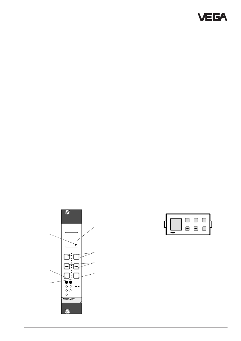
Adjustment with MINICOM or VEGAMET
5.3 Adjustment with VEGAMET or MINICOM
Beside the PC, the VEGAPULS series 40
radar sensors with VBUS output signal can
also be adjusted with
- the signal conditioning instrument
- or the detachable adjustment module
MINICOM.
The adjustment with VEGAMET signal conditioning instrument provides all the adjustment
options available on the PC. Adjustment
takes on a different appearance, but the
scope of the adjustment functions is the
same.
With the adjustment module MINICOM, only
the sensor-relevant adjustments are possible, such as e.g. operating range, measuring
conditions, sensor scaling or false echo
memory. However, all adjustment steps relating to the configuration of the VEGAMET
signal conditioning instrument and its signal
processing (adjustment, configuration of the
inputs and outputs, linearisation curves,
simulation …) are not possible.
Indicating and adjustment panels
VEGAMET signal conditioning instrument
Branching, i.e. jump
to the lower menu
with [OK]
Interrupt adjustment
or jump to the next
higher menu
Analogue
LED display
(0 … 100 %)
ESC
-
12
on
%
100
!
+
OK
CONNECT
515V
Display,
indication of
- measured
value
- menu item
- parameter
- value
Depending on the menu item,
change values or choose out of list
Choose menu window or shift
flashing cursor
Save the adjusted value or move
to the menu below
The adjustment of VEGAMET and the
adjustment of MINICOM are identical.
Adjustment is made with six keys. A small
display shows you, apart from the measured
value, a short message on the menu item or
on the value of a menu adjustment.
The volume of information of the small display,
however, cannot be compared with that of the
adjustment program VVO, but in conjunction
with the following menu schematic of
MINICOM, the adjustment will not be a problem. You might even be able to carry out
adjustments more quickly and directly with
the small adjustment field than with the PC.
Note:
You will find the menu schematic for
VEGAMET in the operating instructions of the
signal conditioning instruments.
Adjustment module
MINICOM
Tank 1
m (d)
12.345
ESC
+
-
OK
VEGAPULS 42, 44 and 45 – VBUS 69
Page 70

Adjustment steps
In the following, you will see the menu
schematic of the adjustment module
MINICOM. The menu schematic of the
VEGAMET signal conditioning instrument is
shown in the operating instructions of the
signal conditioning instrument. Set up the
sensor in the numbered sequence. The
respective numbers are stated in the menu
schematics. Numbers 1 … 4 and 11 you will
find in the menu schematic of the VEGAMET
signal conditioning instrument. Numbers
5 … 10 you will find in the following MINICOM
menu schematic. These numbers can be
adjusted with the MINICOM
MET.
1. Configuration of the measurement loop;
as a rule, already preconfigured (see
operating instructions VEGAMET).
2. Configuration of the input; as a rule, already preconfigured (see operating
instructions VEGAMET).
3. Min/Max. adjustment (see operating
instructions VEGAMET).
4. Conditioning/Scaling VEGAMET (see
operating instructions VEGAMET).
5. Measurement in a standpipe.
6. Operating range.
7. Meas. conditions.
8. False echo memory (only required when
errors occur during operation).
9. Indication of the useful and noise level
10. Conditioning/Scaling of the sensor display .
11. Outputs (see operating instructions
VEGAMET).
and with VEGA-
Adjustment with MINICOM or VEGAMET
1. Configuration of the measurement
loop
(see operating instructions VEGAMET)
First of all, you have to inform the signal conditioning instrument which application (level,
distance, flow, …) you have and which sensor (radar, ultrasonic, …) is connected.
Choose under mode "Standard" and under
option "No option".
2. Configuration of the input
(see operating instructions VEGAMET)
First of all, you have to inform the signal conditioning instrument (only VEGAMET 515V)
which input (input 1 or 2) the sensor is
connected to.
3. Adjustment
(see operating instructions VEGAMET)
Under the menu item "
the sensor which measuring range it should
operate with.
You can carry out the adjustment without and
with medium. Generally, you will carry out the
adjustment without medium, as you can then
adjust without a filling cycle.
Max.
Adjustment
100 % (1.270 m) correspond
to 1200 liters
" you inform
Short explanations to the setup steps 1 … 11
follow.
Min.
70 VEGAPULS 42, 44 and 45 – VBUS
Span (4.58 m)
0 % (5.850 m) corresponds
to 45 liters
Page 71

Adjustment with MINICOM or VEGAMET
Adjustment without medium
(adjustment independent of the actual level)
Key adjustment Display indication
Sensor
m(d)
4.700
Para-
OK
OK
OK
OK
+
The distance indication flashes
and you can choose "feet" and
meter
Adjustment
w.o
medium
Adjustment
in
m(d)
(min. adjustment)
"m".
OK
+ –
or
Confirm the adjustment with
"
OK
".
Adjustment
in
m(d)
0.0%
at
m (d)
XX.XXX
With "+" and "–" you adjust the
percentage value for the min.
value or the lower level (example 0.0 %).
OK
The adjusted product distance is written in the sensor
and the display stops flashing.
You thereby adjusted the lower product distance as well as the percentage filling value
corresponding to the lower product distance.
100.0%
at
m (d)
XX.XXX
(max. adjustment)
The max. adjustment (upper product distance) is made in the same way (example:
100 % and 1.270 m).
Note:
The difference between the adjustment values of the lower product distance and the
upper product distance should be as big as
possible, preferably at 0 % and 100 %. If the
values are very close together, e.g. lower
product distance adjustment at 40 %
(3,102 m) and upper product distance
adjustment at 45 % (3.331 m), the
measurement will be inaccurate. A
characteristics curve is generated from the
two points.
Even the smallest deviations between actual
product distance and entered product distance will considerably influence the slope of
the characteristic curve. When the adjustment points are too close together, small
errors multiply to considerably larger errors
at the output of the 0 % or the 100 % value.
OK
The adjusted percentage
value is written in the sensor
and the distance corresponding to the percentage
Adjustment with medium
(dependent on the actual level)
with
medium
value flashes.
+ –
or
With the "
+
" or "–" key you can
assign a level distance (example 5.85 m) to the previously adjusted percentage
Min.
adjust
at %
XXX.X
Max.
adjust
at %
XXX.X
value. If you do not know the
distance, you have to do a
sounding.
VEGAPULS 42, 44 and 45 – VBUS 71
Page 72

Adjustment with MINICOM or VEGAMET
Fill the vessel e.g. to 10 % and enter 10 % in
the menu "
Min. adjust
" with the "+" and "–"
keys. Then fill the vessel, e.g. to 80 % or
100 % and enter 80 % or 100 % in the menu
"
Max. adjust
" with the "+" and "–" keys. If you
do not know the distance, you have to calculate it by incremental filling.
OK
The indication stops flashing
and the adjustment will be
saved.
You have entered the min. value.
100.0%
at
m (d)
XX.XXX
(max. adjustment)
Enter the max. adjustment like the min. adjustment with "+", "–" or "OK" (example: 1.270
m).
4. Conditioning/Scaling VEGAMET
(see operating instructions VEGAMET)
Under the menu item "
you choose the product distance at 0 % and
at 100 % filling. Then you enter the parameter
and the physical unit as well as the decimal
point, e.g. distance.
Signal
condit
ioning
Scal
ing
Conditioning/Scaling
"
Enter in the menu window "
0 % corresponds
the value of the 0 % filling. In the example of
the adjustment with the PC and the adjustment software VVO this would be 45 for
45 liters.
• Confirm with "
OK
".
With the "—>" key you change to the 100 %
menu. Enter here the value of your parameter
corresponding to a 100 % filling. In the example 1200 for 1200 liters.
• Confirm with "
OK
".
If necessary, choose a decimal point. However, note that only max. 4 digits can be
displayed. In the menu "
prop. to
" you choose
the parameter (mass, volume, distance…)
and in the menu "
Unit
" the physical unit (kg, l,
ft3, gal, m3 …).
Linearisation:
Adjust
ment
Signal
condit
ioning
Scal
ing
Lin.
curve
Linear
Integr
ation
time
0 s
A linear correlation between the percentage
value of the product distance and percentage value of the filling volume is preadjusted.
With the menu "Lin. curve" you can choose
between linear, spherical tank and cylindrical
tank. The creation of one’s own linearisation
curve is only possible with the PC and the
adjustment program VVO.
"
0 %
100 %
Deci-
prop.
corres
corres
ponds
XXXX
mal
point
888.8
ponds
XXXX
72 VEGAPULS 42, 44 and 45 – VBUS
Unit
to
Mass
Kg
Page 73

Adjustment with MINICOM or VEGAMET
5. Measurement in a standpipe
This adjustment is only necessary if the
sensor is mounted on a standpipe (surge or
bypass tube). When measuring in a
standpipe, the distance must be sounded
and the measured value display (can deviate
a few percentages from the sounded value)
must be corrected according to the
sounding. Then the sensor corrects future
running time shifts of the radar signal in the
standpipe and displays the correct level in
the standpipe (meas. tube).
6. Operating range
Without special adjustment, the operating
range corresponds to the measuring range.
The measuring range has already been adjusted with the min./max. adjustment. Generally it is useful to choose a slightly bigger
(approx. 5 %) operating range than measuring range.
Example:
Min./max. adjustment: 0.500 … 3.500 m;
adjust operating range to approx.
0.400 … 3.600 m.
7. Meas. conditions
(see MINCOM menu schematic)
9. Useful and noise level
In the menu
you get important information on the signal
quality of the product echo. The higher the
"S-N" value, the more reliable the measurement (menu schematic MINICOM).
Ampl.: means amplitude of the level echo in
S-N: means Signal-Noise, i.e. the useful
The bigger the "S-N" value (difference between the amplitude useful level and the
noise level), the better the measurement:
> 50 dB Measurement excellent
40 … 50 dB Measurement very good
20 … 40 dB Measurement good
10 … 20 dB Measurement satisfactory
5 … 10 dB Measurement sufficient
< 5 dB Measurement poor
Example:
Ampl. = 68 dB
S-N = 53 dB
68 dB – 53 dB = 15 dB noise level
Ampl.:
XX dB
S-N:
XX
dB
dB (useful level)
level minus the level of the background noise
53 dB signal level difference indicates very
8. False echo storage
A false echo storage is always useful when
unavoidable false echo sources (e.g. struts)
must be minimised. By creating a false echo
high measurement reliability.
10. Conditioning/Scaling of the sensor
display
storage, you authorise the sensor electronics
to record the false echoes and save them in
an internal database. The sensor electronics
treats these (false) echoes differently from
the useful echoes and filters them out.
The menu item "Signal conditioning" in the
MINICOM menu relates only to the sensor
display and will be overwritten by adjustments in the signal conditioning instrument.
11. Outputs
(see operating instructions VEGAMET)
VEGAPULS 42, 44 and 45 – VBUS 73
Page 74

MINICOM menu schematic
Sensor
m(d)
4,700
PULS52
V
1.00
When switching on, the sensor
type and the software version
are displayed for a few seconds.
Adjustment with MINICOM or VEGAMET
Parameter
6.
Sensor
optimisation
Meas.
environment
Operating
range
Begin
m (d)
0.50
Sensor
Tag
Sensor
End
m (d)
6.00
Only visible with
VEGAMET
Meas.
conditions
7.
Condit
ion
Liquid
Sensor
optimisation
see menu schematic
Configuration/Inputs…"
of the VEGAMET signal
conditioning instrument
Measuring in
tube
Meas.
dist.
m (d)
4.700
Correction
Now !
OK ?
Agitat
Fast
ed sur
change
face
No
No
5.
Only with VEGAPULS
42 and 44
Foam-
Low
ing
DK
prod.
product
No
No
False
echo
memory
Create
new
Now !
OK ?
Meas.
in tube
No
8.
Create
new
Meas.
dist.
m (d)
X.XX
Learning !
Multiple
echos
No
Configuration
Sensor
Tag
Sensor
Update
Meas.
dist.
m (d)
X.XX
Update
Now!
OK ?
Learning !
Meas.
unit
m (d)
Delete
Delete
now!
OK ?
Deleting !
Fast
change
No
XXXX
High
dust
level
No
100 %
corres
ponds
XXXX
Decimal
point
Large
angle
repose
No
888.8
Prop.
to
Mass
Multiple
echos
No
Unit
Kg
Outputs
Sensor
displ.
Prop.
to
Distance
Displ.
adjust
ment
Adjustment
in
m (d)
10.
0.0%
at
m (d)
XX.XXX
100.0%
at
m (d)
XX.XXX
Condit
ion
Solid
Signal
conditioning
Scaling
0 %
corres
ponds
74 VEGAPULS 42, 44 and 45 – VBUS
Page 75

Adjustment with MINICOM or VEGAMET
With these keys you move in
the menu field to the left, right,
top and bottom
ESC
Reset
to
default
Reset
Now!
OK ?
Resetting
actual
dist.
m (d)
4.700
see menu schematic "Add'l
funct./Info…" of the
VEGAMET signal condi-
tioning instrument
9.
Ampl.:
XX dB
S-N:
XX
max.
range
m (d)
7.000
OK
actual
dist.
m (d)
4.700
Ampl.:
XX dB
S-N:
XX
dB
Add´l
functions
Info Lan-
Reset
Sensor
Tag
Sensor
to
default
Reset
Now!
Sensor
type
PULS
52 V
dB
Input 1
OK ?
Resetting!
guage
English
Serial
number
1094
0218
Softw.
vers.
3.00
Softw.
date
10.09.
1999
Simulation:
The sensor returns to standard operating
mode after one hour (after the last simulation
setting).
Error code:
E013 No valid measured value
- Sensor in the warm-up phase
actual
dist.
m
X,XX
- Loss of the useful echo
E017 Adjustment span too small
E036 Sensor software does not run
- Sensor must be programmed with
new software (service).
- message appears during a soft-
ware update.
E040 Hardware failure
VEGAPULS 42, 44 and 45 – VBUS 75
High
dust
level
No
Fast
change
No
Menu items in bolt print provide
sensor and measured value
information and cannot be modified
in this position.
Light grey menu fields are only
displayed if required (dependent on
the adjustments in other menus).
White menu items can be modified
with the "+" or "–" key and saved
with the "OK" key.
Page 76

Adjustment with the PC on VEGALOG
5.4 Adjustment with the PC on VEGALOG
For connection of the PC to the VEGALOG
processing system, a standard RS 232 DTEDTE (Data Terminal Equipment) interface
cable is required. Connect the PC with the
cable to the processing system.
DTE DTE
DCD 1 1 DCD
RxD 2 2 RxD
TxD 3 3 TxD
DTR 4 4 DTR
GND 5 5 GND
--- 6 6 ---
--- 7 7 ---
--- 8 8 ---
--- 9 9 ---
Beside the measured values, adjustment
signals are also transmitted digitally between
sensor and processing system via the signal
and supply cable. The adjustment program
VVO can then communicate with the
processing system and all connected sensors. In chapter "4.4 Configuration of measuring systems" the connection of the PC to the
different configurations is shown.
The individual adjustment steps are marked
in the following with a dot.
Example:
• Choose …
• Start …
• Click to …
The first steps of the setup with the PC in
conjunction with the VEGALOG processing
system correspond to the adjustment in
chapter "5.3 Adjustment with VEGAMET or
MINICOM".
• Connect the standard interface of your PC
with the standard RS 232 interlink cable (9pole) to the VEGALOG processing system.
• Now switch on the power supply of the
processing system.
After approx. 1 … 2 minutes (self-test) the
measuring system, consisting of processing
system and sensors, is in operating condition
and the sensors display measured values.
• Now start the adjustment software VVO on
your PC.
• Choose with the arrow keys or the mouse
the item "
Planning
" on the entrance screen
and click to "OK".
In the next window, you are asked for the
user identification.
• Enter under name "VEGA".
• Also enter "VEGA" under password.
The adjustment program VEGA Visual Operating (VVO), called in the following VVO, gets
into contact with the connected sensor and
indicates after a few seconds if and with
which sensor a connection exists.
Note:
If you make no connection with the sensor,
check the following:
- Is the processing system being supplied
with supply voltage?
- Did you inadvertently use a wrong RS 232
cable instead of the VEGA RS 232 connection cable?
76 VEGAPULS 42, 44 and 45 – VBUS
Page 77

Adjustment with the PC on VEGALOG
If VVO (adjustment software) gets in contact
with the processing system for the first time,
you will be asked if you want to transfer the
data from the processing system to the PC.
• Click to "
If you have connected the VVO to a
VEGALOG from which data has already been
saved, you are asked if the saved data
should be transferred from the PC to
VEGALOG or the data from VEGALOG to the
PC.
The preadjusted user identification can be
modified at a later time in the menu "
ration/Program/User access
Yes
".
Configu-
".
Configuration
The adjustment of a radar sensor with the PC
on a VEGALOG generally corresponds to the
adjustment of a radar sensor on the signal
conditioning instrument, as in chapter "5.2
Adjustment with the PC on VEGAMET".
The only difference are the increased configuration requirements of VEGALOG. A
number of possible sensor inputs and signal
outputs as well as different processing
routines must be assigned. First of all, you
must define where and what processing
which sensor (input) does.
Configuration info
• Choose the menu "
ing system
Configuration/Measur-
".
No matter whether you set up a measuring
system (unit consisting of sensor and
VEGAMET signal conditioning instrument or
VEGALOG processing system) with the
adjustment software VVO or with the signal
conditioning instrument, the adjustment procedure is always the same:
- first of all, create a measurement loop and
configure a measuring system in the menu
"
Configuration
- carry out the parameter adjustment of the
sensor in the menu "
VEGAPULS 42, 44 and 45 – VBUS 77
" and then
Instrument data
".
You now reach the menu "
Measuring system
representation of the VEGALOG connected
to the PC is displayed.
• Click to an individual card number and you
will get a "Card info" in the window
Configuration
", in which a graphical
.
Page 78

Adjustment with the PC on VEGALOG
Create new measurement loop
• Click in the card info window of your EV
card (input card VBUS) to "
Sensor survey"
You get an overview of the sensors connected to the card.
• Choose the menu "
ment loop/New
.
Configuration/Measure-
".
You are in the menu window "
measurement loop - Application
Create new
". Choose the
parameter (level measurement, gauge or
distance) and the sensor type (Pulse Radar
for radar).
• Choose "
Radar
• Click to "
78 VEGAPULS 42, 44 and 45 – VBUS
Level measurement
".
Continue
".
" and "
Pulse
Page 79

Adjustment with the PC on VEGALOG
• Choose in the next menu window "
ard level measurement
• Click to "
After a few seconds, the menu window "
Continue
" and "
".
Stand-
no options
Cre-
".
ate new measurement loop - Sensor configuration
" opens.
• Click to "
The small menu window "
opens.
Sensor coordination
Sensor coordination
".
• Choose the serial number of the sensor
you want to coordinate and confirm with
"OK".
• Click in the menu window "
Create new
measurement loop - Sensor configuration
to "
Continue
• Click in the menu window "
".
Create new
measurement loop - Measurement loop
designation
"
" to "
Level
".
"
VEGAPULS 42, 44 and 45 – VBUS 79
Page 80

Adjustment with the PC on VEGALOG
The menu window "
loop - Measurement loop designation
Enter:
- a measurement loop number
- a measurement loop description
- allocate one or several output signals to
your sensor.
• For example, configure a current output by
clicking to "
In the menu window "
put
", you choose a current output card in
your VEGALOG and allocate one or several
current outputs to the sensor.
Create new measurement
Current output
".
Configure current out-
" opens.
• Confirm your adjustments with "OK".
• Click to "
initial menu.
Quit
" and you are again in the
You have carried out the special additional
configuration settings in conjunction with a
VEGALOG.
• Confirm your adjustment with "OK" and you
are again in the window "
Create new meas-
In the menu "
tem"
you now see that one sensor is
configured.
Configuration/Measuring sys-
urement loop - Measurement loop designation
".
80 VEGAPULS 42, 44 and 45 – VBUS
Page 81

Adjustment with the PC on VEGALOG
Parameter adjustment 1
Now you have to carry out the parameter
adjustment for the sensor. The parameter
adjustment is nearly identical to the parameter adjustment in chapter "5.2 Adjustment
with the PC on VEGAMET".
In the menu "
justment
settings. The settings correspond to those
under parameter adjustment 1 in chapter "5.2
Adjustment with the PC on the signal conditioning instrument".
The same is valid for the following menu items
corresponding to the adjustment steps in
chapter "5.2 Adjustment with the PC on the
signal conditioning instrument". For this reason, they are not described again in this
paragraph.
•
Sensor optimisation
- Meas. environment/Operating range
- Meas. environment/Meas. conditions
- Meas. environment/Pulse velocity
- Echo curve
- False echo storage
•
Parameter adjustment 2
- Linearisation
- User-programmable linearisation curves
- Defining the linearisation curve by incremental filling
- Calculating the linearisation curve
- Calculate cylindrical tank
•
Outputs
- Configuration outputs
- Parameter adjustment outputs
•
Display of measured value
•
Simulation
•
Backup
Instrument data/Parameter ad-
" you carry out all important sensor
VEGAPULS 42, 44 and 45 – VBUS 81
Page 82

6 Diagnosis
Diagnosis
6.1 Simulation
To simulate a certain filling, you can call up
the function "Simulation" on the adjustment
module MINICOM, in the software program
VVO or on the signal conditioning instrument.
You simulate a vessel filling and thereby a
certain sensor current. Please note that connected instruments, such as e.g. a PLC react
according to their adjustments and will probably activate alarms or system functions.
Simulation with VVO
If you start the simulation mode with the adjustment program VVO on the PC, the simulated level is outputted until you quit the
simulation mode.
Simulation with VEGAMET
If you call up the simulation mode with the
adjustment keys on the signal conditioning
instrument, 15 minutes after the last adjustment the signal conditioning instrument returns to standard operating condition.
Simulation with MINICOM
If you start the simulation mode on the adjustment module MINICOM, the sensor returns to
standard operating mode after one hour.
6.2 Error code
Error code Rectification
E013 No valid measured value Message is displayed during warm-up phase
- Sensor in the warm-up phase
- Loss of the useful echo If the message remains, a false echo storage
must be made with the adjustment module
MINICOM in the menu "sensor optimisation” or
better, with the PC and VVO.
If the message still remains, carry out a new
adjustment.
E017 Adjustment span too small Carry out a readjustment.
E036 Sensor software does not run Sensor must be programmed with new software
E040 Hardware failure/Electronics defec- Check all connection cables.
tive Transducer defective.
82 VEGAPULS 42, 44 and 45 – VBUS
Make sure that the difference between
min. and max. adjustment is at least 10 mm.
(service).
Message appears during a software update.
Contact our service department.
Page 83

Technical data
7 Technical data
7.1 Data
Power supply
Supply voltage The sensor is powered by the VEGAMET signal
Number of sensors per two-wire cable VEGAMET max. 2 sensors
Sensor voltage min. 12 V, max. 36 V DC (Ex: max. 29 V DC)
Current consumption max. 6 mA
Power consumption max. 81 mW
Resistance of the signal cable max. 15 Ω per wire
Cable length
-1.5 mm
-1 mm
- 0.75 mm
Measuring range
2
and 2.5 mm
2
2
1)
2
VEGAPULS 42
- standard ø 40 mm horn 0 … 10 m
- optional
ø 48 mm horn 0 … 15 m
ø 75, 95 mm horn 0 … 20 m
VEGAPULS 44
- DN 50, ANSI 2" 0 … 15 m
- DN 80, 100, ANSI 3", 4", 6" 0 … 20 m
VEGAPULS 45 0 … 4 m
conditioning instrument, the VEGALOG processing system or the VEGATRENN 548V Ex
separator
VEGALOG max. 15 sensors (recommended 5)
VEGATRENN (Ex) max. 5 sensors
max. 1000 m
max. 840 m
max. 630 m
Output signal
Signal output digital VBUS output signal in two-wire technology
(VEGA-Bus).
the digital output signal (meas. signal) is
modulated to the power supply and further
processed in the signal conditioning instrument
or in the processing system.
Integration time (adjustable)
- in the sensor 0 … 999 seconds
- in the signal conditioning instrument 0 … 600 seconds
Load resistance of the signal cable max. 15 Ohm per
wire and max. 1000 m cable length
(with 15 sensors on one two-wire cable
max. 10 Ohm per wire)
1)
Min. distance of the antenna to the medium 5 cm
VEGAPULS 42, 44 and 45 – VBUS 83
Page 84

Technical data
Measured value display (optional)
Liquid-crystal indication
- in the sensor scalable output of measured values as graph
and as number
- in the external indicating instrument scalable output of measured values as graph
powered by the sensor and as number. Measured value display can be
mounted up to 25 m away from the sensor
Adjustment
- PC and adjustment software VEGA Visual Operating
- adjustment module MINICOM
- VEGA signal conditioning instrument
Accuracy
1)
(typical value under reference conditions, all statements relate to the nominal
measuring range, for type 45 relating to a measuring range of 4 m)
Characteristics linear
Accuracy (deviation in characteristics
incl. linearity, repeatability and
hysteresis determined by the
limit point method) < 0.05 %
Average temperature coefficient
of the zero signal 0.06 %/10 °K
Resolution generally max. 1 mm
Resolution of the output signal 0.005 % or 1 mm
Characteristics
1)
(typical values under reference conditions, all statements refer to the nomi-
nal measuring range)
Min. span between
full and empty > 10 mm (recommended > 50 mm)
Frequency 26 GHz technology
Meas. intervals 0.6 s
Beam angle (at -3 dB)
- VEGAPULS 42 22°
optional 18°, 10° and 8° bigger coupling horns, deviating
from standard dimensions
- VEGAPULS 44
DN 50, ANSI 2" 18°
DN 80, ANSI 3" 10°
DN 100, ANSI 4" 8°
DN 150, ANSI 6" 8°
Adjustment time (response time) > 1 s (dependent on the parameter setting)
Influence of the process temperature cannot be measured at 0 bar;
at 5 bar 0.004 %/10 °K;
at 40 bar 0.03 %/10 °K
Influence of the process pressure 0.0265 %/bar
Adjustment time
Radar emitted power (average) 0.717 µW
Received average emitted power
2)
3)
> 1 s (dependent on the parameter setting)
- distance 1 m 0.5 … 1.5 nW per cm² (0.5 … 1.5 x 10⁻⁹W/cm²)
- distance 5 m 0.02 … 0.6 nW per cm²
1) 2) 3)
See footnotes on next page
84 VEGAPULS 42, 44 and 45 – VBUS
Page 85

Technical data
Ambient conditions
Vessel pressure -1 … 16 bar (-100 … 1600 kPa)
-1 … 40 bar (-100 … 4000 kPa)
Ambient temperature on the housing -30 °C … +80 °C
Process temperature (flange temp.) -20 °C … +150 °C (option -40 °C … +150 °C)
Storage and transport temperature -60 °C … +80 °C
Protection IP 66 and IP 67
Protection class II
Overvoltage category III
Ex technical data
Comprehensive data in the attached approval documents (yellow binder)
Intrinsically safe version
- classification ia intrinsically safe in conjunction with a separator
or safety barrier
- classification mark II 2G EEx ia II T6
- Ex approved Zone 1 (ATEX)
Zone 1 (CENELEC, PTB, IEC)
or
- classification mark II 1G EEx ia IIC T6
- Ex approved Zone 0, Zone 1 (ATEX)
Zone 0, Zone 1 (CENELEC, PTB, IEC)
Permissible ambient temperature
on the housing
- T6 -40 °C … +55 °C
- T5 -40 °C … +70 °C
- T4, T3 -40 °C … +85 °C
- T2, T1 -40 °C … +70 °C
Permissible ambient temperature on the
antenna system if used in Ex areas
- T6 -40 °C … +85 °C
- T5 -40 °C … +100 °C
- T4 -40 °C … +135 °C
- T3 -40 °C … +150 °C
1)
Similar to DIN 16 086, reference conditions acc. to IEC 770, e.g.
temperature 15 °C … 35 °C; humidity 45 % … 75 %; air pressure 860 mbar … 1060 mbar
2)
The adjustment time (also called actuating time, response time or adjustment period) is the time required by
the sensor to output the correct level (with max. 10% deviation) after a sudden level change.
3)
Average emitted power (electromagnetic energy) per cm² received on an object directly in front of the
antenna. The received emitted power depends on the antenna version and the distance.
VEGAPULS 42, 44 and 45 – VBUS 85
Page 86

Technical data
Process fittings
VEGAPULS 42 thread G 1½ A, 1½" NPT
antenna as horn with ø 40 mm
antenna horns from ø 48 … 95 mm (can be
retrofitted optionally)
VEGAPULS 44 flanges with DN 50, DN 80, DN 100, DN 150
as well as ANSI 2", 3", 4" and 6"
antenna as horn (antenna horns from
ø 48 … 95 mm dependent on the flange size)
VEGAPULS 45 flanges with DN 50, DN 80, DN 100, DN 150
as well as ANSI 2", 3", 4" and 6" or
thread G 1½ A, 1½" NPT
Materials
Housing PBT (Valox) or
Aluminium die-casting (GD-AlSi 10 Mg)
Process fitting 1.4435
Antenna (wetted parts) 1.4435 and PTFE
Antenna seal with
horn and pipe antenna
- standard Viton (-20 °C)
- option Kalrez, NBR, Viton for low temperature (-40 °C)
Connection cables
Two-wire sensors Vpower supply and signal via one two-wire
cable
Electrical connection
- cable entry one cable entry and spring terminal connection
up to max. 2.5 mm
2
wire cross-section
- plug connection optional for plastic housing:
four-pole reverse battery screw connection
(four-wire: two plug connections)
Cable entry
- non-Ex and Ex ia sensors 1 … 2 x M20 x 1.5 (cable ø 5 … 9 mm) or
1 … 2 x ½" NPT cable ø 3.6 … 8.7 mm or
Ground connection max. 4 mm
0.12 … 0.34 inch)
2
86 VEGAPULS 42, 44 and 45 – VBUS
Page 87

Technical data
Weights
VEGAPULS 42 2.0 … 3.1 kg
VEGAPULS 44
- DN 50 4.2 … 5.0 kg
- DN 80 6.8 … 7.6 kg
- DN 100 8.0 … 9.1 kg
- DN 150 13.2 … 14.3 kg
- ANSI 2" 5.2 … 5.7 kg
- ANSI 3" 6.9 … 7.5 kg
- ANSI 4" 10.5 … 11.1 kg
- ANSI 6" 14.6 … 15.4 kg
VEGAPULS 45 (plus meas. tube weight)
- G 1½ A or 1½" NPT 2.0 … 3.8 kg
- DN 50 4.2 … 6.0 kg
- DN 80 5.9 … 7.7 kg
- DN 100 7.0 … 8.8 kg
- DN 150 11.8 … 13.7 kg
- ANSI 2" 3.7 … 5.6 kg
- ANSI 3" 6.2 … 8.0 kg
- ANSI 4" 8.3 … 10.1 kg
- ANSI 6" 12.8 … 14.6 kg
Meas. tube weight 1.6 kg per m
CE conformity
VEGAPULS series 40 radar sensors meet the protective regulations of EMC (89/336/EWG)
and NSR (73/23/EWG). Conformity has been judged acc. to the following standards:
EMC Emission EN 61 326: 1997/A1: 1998 (class B)
Susceptibility EN 61 326: 1997/A1: 1998
ATEX EN 50 020: 1994
EN 50 018: 1994
EN 50 014: 1997
NSR EN 61 010 - 1: 1993
VEGAPULS 42, 44 and 45 – VBUS 87
Page 88

Technical data
7.2 Approvals
When using radar sensors in Ex areas or in
marine applications, the instruments must be
suitable and approved for the explosion
zones and application areas.
The suitability is tested by approval authorities and is certified in approval documents.
Intrinsically safe in Ex environment
For application in Ex environment,
VEGAPULS 42.CX to 45.CX sensors must be
powered from an intrinsically safe circuit. This
is ensured by VEGATRENN 548V Ex separators. The separator provides intrinsically safe
(ia) circuits. The resistance of the signal
cable must not exceed 15 Ohm per wire.
VEGAPULS 42.AX to 45.AC sensors are
approved for Ex Zone 1. VEGAPULS 42.CX
to 45.CX sensors are approved for Ex Zone
0.
Please note the attached approval documents when using a sensor in Ex area.
Test and approval authorities
VEGAPULS radar sensors are tested and
approved by the following monitoring, test
and approval authorities:
- PTB
(Physical Technical Test Authority Physikalisch Technische Bundesanstalt)
- FM
(Factory Mutual Research)
- ABS
(American Bureau of Shipping)
- LRS
(Lloyds Register of Shipping)
- GL
(German Lloyd)
- CSA
(Canadian Standards Association)
88 VEGAPULS 42, 44 and 45 – VBUS
Page 89

Technical data
7.3 Dimensions
External indicating instrument VEGADIS 50
85
38
ø5
48
10
Pg 13,5
Mounting on carrier rail 35 x 7.5 acc. to EN 50 022 or flat
screwed
118
108
135
Flange dimensions acc. to ANSI (RF)
d
2
f
d
1
k
D
82
b
Note:
Cable diameter of the connection cable min.
5 mm and max. 9 mm.
Otherwise the seal effect of the cable entry
85
will not be ensured.
D = outer flange diameter
b = flange thickness
k = diameter of hole circle
d
= seal ledge diameter
1
f = seal ledge thickness
1
/16" = approx. 1.6 mm
d
= diameter of holes
2
Size Flange Seal ledge Holes
Db k d1No. d
2
2" 150 psi 152.4 20.7 120.7 91.9 4 19.1
3" 150 psi 190.5 25.5 152.4 127.0 4 19.1
4" 150 psi 228.6 25.5 190.5 157.2 8 19.1
6" 150 psi 279.4 27.0 241.3 215.9 8 22.4
Adjustment module MINICOM
ESC
+
-
Tank 1
m (d)
12.345
67,5
74
VEGAPULS 42, 44 and 45 – VBUS 89
32,5
OK
Adjustment module to plugped into sensors or
into the external indicating instrument
VEGADIS 50
Page 90

Sensor dimensions
Technical data
PBT Aluminium
201
165
101
199
ø 40
307
253
G1½ A
1½" NPT
322
SW 60
G½A
1½NPT
182
ø 40
G1½ A
1½" NPT
ø 40
22
1
0
125
100
˚
M20x1,5
145
0
7
3
PBT: 53
Al: 78
Aluminium with Exd
terminal compartment
215
185
5
0
2
135
18
ø 40
ø 48
19
25
116
0
7
3
5
0
M20x1,5
139
2
ø 75
215
185
20
219
ø 95
116
25
½" NPT
20
319
8
1
ø
ø18
45˚
8
1
ø
VEGAPULS 42
ø 125
ø 165
DN 50 PN 40 (C)
ANSI 2" (RF)
ø 160
ø 200
DN 80 PN 40 (C)
ANSI 3" (RF)
ø 180
ø 220
DN 100 PN 16 (C)
ANSI 4" (RF)
VEGAPULS 44
90 VEGAPULS 42, 44 and 45 – VBUS
45˚
Page 91

Technical data
Recommended max. socket length for VEGAPULS 42 and 44
dependent on the antenna version:
Sensor type Version Socket length Socket length
with antenna extension
VEGAPULS 42 Standard 135 mm 250 mm
VEGAPULS 44 DN50/ANSI 2" 135 mm 245 mm
DN 80/ANSI 3" 210 mm 325 mm
DN 100/ANSI 4" 310 mm 425 mm
DN 150/ANSI 6" 310 mm 425 mm
20
ø 95
ø 40
108
319
ø 165…285
18…22
ø 27
125 65
22
125 65
29
ø 27
ø22
ø 240
ø 285
DN 150 PN 16 (C)
4
5
˚
DN 50…DN 150 PN 16/40 (C)
ANSI 2"…ANSI 6" (RF)
L max. 4000
L max. 4000
G1½ A
1½" NPT
ANSI 6" (RF)
VEGAPULS 45VEGAPULS 44
VEGAPULS 42, 44 and 45 – VBUS 91
Page 92

VEGA Grieshaber KG
Am Hohenstein 113
D-77761 Schiltach
Phone (07836) 50-0
Fax (07836) 50-201
E-Mail info@de.vega.com
www.vega.com
ISO 9001
All statements concerning scope of delivery, application, practical
use and operating conditions of the sensors and processing systems correspond to the latest information at the time of printing.
Technical data to subject to alterations
2.24 903 / April 2001
 Loading...