

Page 1
FL SWITCH SFN…
Five- and Eight-Port Standard Function Ethernet
Switches with Narrow Housings –
Gigabit as an Option
AUTOMATION
Data Sheet
2732_en_D
© PHOENIX CONTACT 2011-01-26
1Description
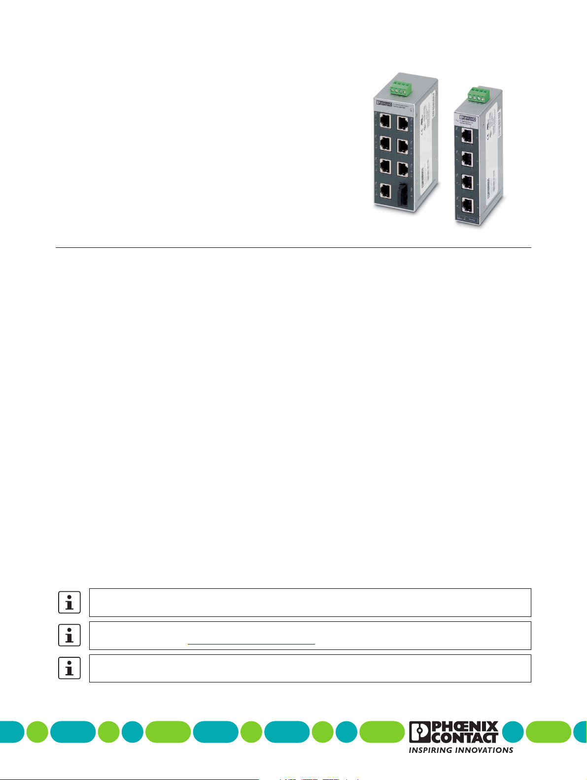
The FL SWITCH SFN… range of Factory Line switches with
standard functions in numerous versions can be used for
quick and cost-effective Ethernet network expansion to the
field level. Due to their narrow housing design, the
components are suitable for universal remote use in control
cabinets and junction boxes. The switches have five or eight
ports, up to two of which are glass fiber ports provided in SC
or ST format. The switches support the auto negotiation
function at the twisted pair ports and offer transmission
speeds of 10/100/1000 Mbps depending on the switch
version. Mixed operation for the connection of segments
with different data transmission speeds is also supported.
The glass fiber ports only support 100 Mbps or 1000 Mbps
(Gigabit version).
The RJ45 ports offer an auto crossing function, which means
it is not necessary to make a distinction between 1:1 and
crossover cables.
The fiber optic ports can be used to extend the segment
length up to 20 km. Unused RJ45 ports can be fitted with
security caps to provide mechanical protection against
unauthorized use.
The FL SWITCH SFN…GT… switches offer additional
gigabit performance, alarm contact and redundant power
input capability.
2Features
– Increased network performance
– Switched Ethernet reduces traffic and non
predictable timing
– Quality of Service: Pretagged high priority
messages are forwarded before lower priority
messages during periods of high network traffic
loading
– Gigabit options for data intensive applications
– Gigabit switches support jumbo frames up to
9600 bytes per frame
– Easy network expansion
– No configuration of the switch
– Auto negotiation and autocross simplify cabling
– Coupling copper network segments with different
bit rates with automatic detection of the data
transmission speed of 10 Mbps, 100 Mbps or
1000 Mbps depending on the switch version
– Fiber optic options extend distance and electrical noise
immunity
– 1- or 2-port options
– SC or ST connector options
– Multimode or singlemode option
– Low cost, low complexity security (optional)
– Connect Layer 1 security elements at the RJ45 port
to restrict access or tampering
Please note the different connection directions of the transmission media for five-port switches: copper cables
are connected at the front, glass fiber cables at the bottom.
Make sure you always use the latest documentation.
It can be downloaded at www.phoenixcontact.net/catalog
This data sheet is valid for all products listed on the following page:
.
Page 2

FL SWITCH SFN…
– No software setup needed
3Ordering Data
Ethernet Switches with 10/100 Mbps
Description Type Order No. Pcs./Pkt.
Ethernet switch with 5 RJ45 ports for 10/100 Mbps FL SWITCH SFN 5TX 2891152 1
Ethernet switch with 4 RJ45 ports and
1 fiber optic port in SC format for 10/100 Mbps
Ethernet switch with 4 RJ45 ports and
1 fiber optic port in ST format for 10/100 Mbps
Ethernet switch with 8 RJ45 ports for 10/100 Mbps FL SWITCH SFN 8TX 2891929 1
Ethernet switch with 7 RJ45 ports and
1 fiber optic port in SC format for 10/100 Mbps
Ethernet switch with 7 RJ45 ports and
1 fiber optic port in ST format for 10/100 Mbps
Ethernet switch with 6 RJ45 ports and 2 fiber optic ports in SC format FL SWITCH SFN 6TX/2FX 2891314 1
Ethernet switch with 6 RJ45 ports and
2 fiber optic ports in ST format for 10/100 Mbps
Ethernet Switches with 10/100/1000 Mbps (Gigabit)
Description Type Order No. Pcs./Pkt.
Ethernet switch with 8 RJ45 ports for 10/100/1000 Mbps FL SWITCH SFN 8GT 2891673 1
Ethernet switch with 7 RJ45 ports for 10/100/1000 Mbps and 1 fiber optic port
in SC format (multi-mode), 850 nm up to 550 m distance
Ethernet switch with 6 RJ45 ports for 10/100/1000 Mbps and 2 fiber optic ports
in SC format (multi-mode), 850 nm up to 550 m distance
Ethernet switch with 6 RJ45 ports for 10/100/1000 Mbps and 2 fiber optic ports
in SC format (single mode), 1310 nm up to 10 km distance
Ethernet switch with 6 RJ45 ports for 10/100/1000 Mbps and 2 fiber optic ports
in SC format (single mode), 1310 nm up to 20 km distance
FL SWITCH SFN 4TX/FX 2891851 1
FL SWITCH SFN 4TX/FX ST 2891453 1
FL SWITCH SFN 7TX/FX 2891097 1
FL SWITCH SFN 7TX/FX ST 2891110 1
FL SWITCH SFN 6TX/2FX ST 2891411 1
FL SWITCH SFN 7GT/SX 2891518 1
FL SWITCH SFN 6GT/2SX 2891398 1
FL SWITCH SFN 6GT/2LX 2891987 1
FL SWITCH SFN 6GT/2LX-20 2891563 1
Accessories
Description Type Order No. Pcs./Pkt.
Universal end clamp E/NS 35 N 0800886 50
Dust protection caps for RJ45 female connectors FL RJ45 PROTECT CAP 2832991 10
Patch angle with 2 ports in CAT 5e FL PF 2TX CAT5E 2891165 1
Patch angle with 8 ports in CAT 5e FL PF 8TX CAT5E 2891178 1
Patch angle with 2 ports in CAT 6 FL PF 2TX CAT6 2891068 1
Patch angle with 8 ports in CAT 6 FL PF 8TX CAT6 2891071 1
Patch angle with security elements for 2 ports in CAT 5e FL PF SEC 2TX 2832687 1
Patch angle with security elements for 8 ports in CAT 5e FL PF SEC 8TX 2832690 1
Patchbox 8 x RJ45 CAT 5e, pre-assembled, can be retrofitted FL PBX 8TX 2832496 1
Patchbox 6 x RJ45 CAT 5e and 4 SC-RJ, glass pre-assembled, can be
retrofitted
Patch cable, CAT 5, pre-assembled, 0.3 m long FL CAT5 PATCH 0,3 2832250 10
Patch cable, CAT 5, pre-assembled, 0.5 m long FL CAT5 PATCH 0,5 2832263 10
Patch cable, CAT 5, pre-assembled, 1.0 m long FL CAT5 PATCH 1,0 2832276 10
Patch cable, CAT 5, pre-assembled, 1.5 m long FL CAT5 PATCH 1,5 2832221 10
Patch cable, CAT 5, pre-assembled, 2.0 m long FL CAT5 PATCH 2,0 2832289 10
Patch cable, CAT 5, pre-assembled, 3.0 m long FL CAT5 PATCH 3,0 2832292 10
Patch cable, CAT 5, pre-assembled, 5.0 m long FL CAT5 PATCH 5,0 2832580 10
Patch cable, CAT 5, pre-assembled, 7.5 m long FL CAT5 PATCH 7,5 2832616 10
Patch cable, CAT 5, pre-assembled, 10.0 m long FL CAT5 PATCH 10 2832629 10
Security set for 4 RJ45 ports FL SEC PAC 4TX 2832865 4
Security frame for SFN switch and patch fields, green FL PLUG GUARD, GN 2891615 20
2732_en_D PHOENIX CONTACT 2
FL PBX 6TX/4FX 2832506 1
Page 3

FL SWITCH SFN…
Accessories
Description Type Order No. Pcs./Pkt.
Security frame for SFN switch and patch fields, red FL PLUG GUARD, RD 2891712 20
Security frame for SFN switch and patch fields, white FL PLUG GUARD, WH 2891819 20
Security frame for SFN switch and patch fields FL PORT GUARD 2891220 20
Security frame for SFN switch and patch fields FL PLUG GUARD KEY 2891327 1
Security element for FL CAT patch FL PATCH SAFE CLIP 2891246 20
4 Technical Data
General Data
Function Switch/repeater; conforms to standard IEEE 802.3
Latency of the communication processor 8 µs plus frame time
Housing dimensions (width x height x depth)
5-port switch, without connectors
8-port switch, without connectors
Operating temperature
FL SWITCH SFN …TX… and FL SWITCH SFN 6GT/2LX-20
FL SWITCH SFN 8GT, FL SWITCH SFN 6GT/2SX,
FL SWITCH SFN 7GT/SX
FL SWITCH SFN 6GT/2LX
Storage temperature
FL SWITCH SFN…TX… switches
FL SWITCH SFN…GT… switches (not FL SWITCH SFN 6GT/2LX-20)
FL SWITCH SFN 6GT/2LX-20
Degree of protection IP20, DIN 40050, IEC 60529
Protection class Class 3 VDE 0106; IEC 60536
Humidity (operation and storage) 5% to 95%, no condensation
Air pressure (operation) 86 kPa to 108 kPa, 1500 m above sea level
Air pressure (storage) 66 kPa to 108 kPa, 3500 m above sea level
Mounting NS 35 (EN 60715)
Preferred mounting position Perpendicular to a standard DIN rail
Connection to protective ground Snapped onto a grounded DIN rail
Weight, without connectors
5-port switch
8-port switch
30 x 120 x 100 mm (without COMBICON/without fiber optics)
50 x 120 x 100 mm (without COMBICON/without fiber optics)
0 to 60°C
-25 to 75°C
-25 to 60°C
-20 to 70°C
-35 to 85°C
-20 to 70°C
265 g
440 g
Supply Voltage (US)
Connection type Removable COMBICON, screw-cage connector
Wire size (solid/stranded/AWG) 0.2 to 2.5 mm² / 0.2 to 2.5 mm² / 24 to 12 AWG
Recommended PE wire size 2.5 mm²
Nominal power supply 12 or 24 V DC
Permissible ripple 3.6 V
Permissible voltage range 9VDC to 30.2VDC
Test voltage 500 V DC for one minute
Protection against polarity reversal Present
2732_en_D PHOENIX CONTACT 3
within the permissible voltage range
pp
Page 4

FL SWITCH SFN…
Current Consumption and Inrush Current
Current Consumption (max) Inrush Current
FL SWITCH SFN 5TX 90 mA (24 V DC)/205 mA (9 V DC) 2.3 A for 3 ms
FL SWITCH SFN 4TX/FX 140 mA (24 V DC)/405 mA (9 V DC) 2.4 A for 2 ms
FL SWITCH SFN 4TX/FX ST 140 mA (24 V DC)/405 mA (9 V DC) 2.9 A for 2 ms
FL SWITCH SFN 8TX 140 mA (24 V DC)/340 mA (9 V DC) 3.1 A for 2 ms
FL SWITCH SFN 7TX/FX 190 mA (24 V DC)/480 mA (9 V DC) 3.4 A for 2 ms
FL SWITCH SFN 7TX/FX ST 190 mA (24 V DC)/480 mA (9 V DC) 3.4 A for 2 ms
FL SWITCH SFN 6TX/2FX 230 mA (24 V DC)/610 mA (9 V DC) 3.6 A for 2 ms
FL SWITCH SFN 6TX/2FX ST 230 mA (24 V DC)/610 mA (9 V DC) 3.3 A for 2 ms
FL SWITCH SFN 8GT 430 mA (24 V DC)/1010 mA (9 V DC) 3.1 A for 3 ms
FL SWITCH SFN 7GT/SX 320 mA (24 V DC)/900 mA (9 V DC) 4.2 A for 3 ms
FL SWITCH SFN 6GT/2SX 350 mA (24 V DC)/960 mA (9 V DC) 4.4 A for 3 ms
FL SWITCH SFN 6GT/2LX 360 mA (24 V DC)/950 mA (9 V DC) 4.4 A for 3 ms
FL SWITCH SFN 6GT/2LX-20 360 mA (24 V DC)/990 mA (9 V DC) 4.4 A for 3 ms
Interfaces
Total number of RJ45 Ethernet interfaces 5/8
MAC Address Table Size (Entries) 1 K (4, 5, 8 TX versions), 8 K (all others)
Properties of RJ45 Ports
Number 4/5/6/7/8
Connection format 8-pos. RJ45 female connector on the switch
Connection medium Twisted-pair cable with a conductor cross section of 0.14 mm2 to 0.22 mm
Cable impedance 100 Ω
Transmission speed 10/100 Mbps or 10/100/1000 Mbps
Maximum network segment length 100 m
Properties of Fiber Optic Ports
Number 0/1/2
Connection format
100 Mbps
1000 Mbps
Fiber type Glass
Laser protection Class 1 according to DIN EN 60825-1:2001-11
Properties of 100 Mbps Multimode
Transmission rate 100 Mbps full duplex
Wavelength 1300/1310 nm
Maximum transmission length, including 3 dB system reserve and 1.5 dB
connector loss
Transmission power (medium type) dynamic (average)
Minimum
Maximum
Transmission power (medium type) static
Minimum
Maximum
Receiver sensitivity
Minimum
Maximum
Properties of 1000 Mbps Multimode
Transmission rate 1.25 Gbps full duplex
Wavelength 850 nm
SC duplex or ST female connector
SC duplex
5.4 km glass fiber with F-G 50/125 0.7 dB/km F1200
2.4 km glass fiber with F-G 50/125 1.6 dB/km F800
10.4 km glass fiber with F-G 62.5/125 0.7 dB/km F1000
2.8 km glass fiber with F-G 62.5/125 2.6 dB/km F600
-23.5 dBm (50/125 µm) / -20 dBm (62.5/125 µm)
-14 dBm (50/125 µm) / -14 dBm (62.5/125 µm)
-22.5 dBm (50/125 µm) / -19 dBm (62.5/125 µm)
-14 dBm (50/125 µm) / -14 dBm (62.5/125 µm)
-31 dBm (dynamic) / -31 dBm (static)
-14 dBm (dynamic) / -14 dBm (static)
2
2732_en_D PHOENIX CONTACT 4
Page 5

Interfaces (Continued)
Maximum transmission length 550 m (50/125 µm)
220 m (62.5/125 µm)
Transmission power
Minimum
Maximum
Receiver sensitivity
Minimum
Maximum
Properties of 1000 Mbps single mode
Transmission rate 1.25 Gbps full duplex
Wavelength 1310 nm
Maximum transmission length
FL SWITCH 6GT/2LX
FL SWITCH 6GT/2LX-20
Transmission power
Minimum
Maximum
Receiver sensitivity
Minimum
Maximum
Alarm Contacts (FL SWITCH SFN…GT… only)
Voltage 24 V DC typical
Current carrying capacity 100 mA maximum including inrush
-9.5 dBm
-4 dBm
-17 dBm
-3 dBm
10 km (9/125 µm)
20 km (9/125 µm)
-10 dBm
-3 dBm
-24 dBm
-0 dBm
FL SWITCH SFN…
Mechanical Tests
Shock test according to IEC 60068-2-27 Operation: 25g, 11 ms period, half-sine shock pulse
Vibration resistance according to IEC 60068-2-6 Operation/storage/transport: 5g, 150 Hz, Criterion 3
Free fall according to IEC 60068-2-32 1 m
Storage/transport: 50g, 11 ms period, half-sine shock pulse
Conformance With EMC Directives
Developed according to IEC 61000-6-2
IEC 61000-4-2 (ESD) Criterion B
IEC 61000-4-3 (radiated-noise immunity) Criterion A
IEC 61000-4-4 (burst) Criterion A
IEC 61000-4-5 (surge) Criterion B
IEC 61000-4-6 (conducted noise immunity) Criterion A
IEC 61000-4-8 (noise immunity against magnetic fields) Criterion A
EN 55022 (noise emission) Class A
Approvals
FL SWITCH SFN…TX… switch c u ROHS EEE 2002/95/EC, WEEE 2002/96/EC,
U Class I, Division 2, Groups A, B, C, D Temp Code T5
installed in minimum IP54 enclosure
FL SWITCH SFN…GT… switch c u ROHS EEE 2002/95/EC, WEEE 2002/96/EC
U Class I, Division 2, Groups A, B, C, D Temp Code T4
installed in minimum IP54 enclosure
2732_en_D PHOENIX CONTACT 5
Page 6

FL SWITCH SFN…
LNK/ACT
100
X5
X1
X2
X3
X4
FL SWITCH SFN 5TX
Ord.-No.:2891152
100
LN
K
/
AC
T
100
LN
K
/
AC
T
100
LN
K
/
AC
T
100
LN
K/
AC
T
LNK/ACT
100
X5
X1
X2
X3
X4
FL SWITCH SFN 4TX/FX ST
Ord.-No.:2891453
100
LN
K
/
AC
T
100
LN
K
/
AC
T
100
LN
K
/
AC
T
100
LN
K
/
AC
T
LNK/ACT
X5
FL SWITCH SFN 5TX
FL SWITCH SFN 5TX
with FL SEC PAC
FL SWITCH SFN 4TX/FX ST
72671000
Differences Compared to Previous Versions
7267 Version 00 - First version
7267 Version 01 - Update Gigabit, supply voltage, current consumption, surge and approvals
7267 Version 02 - Update 1000 Mbps multimode
2732 Document number was 7267 - Added jumbo frame content, edited operating temperature ranges, updated approval information, reformatted
2732B - Corrected transmission speed LED indications (Section 5.5) and clarified FL SWITCH SFN…GT… capability.
5Overview
5.1 5-port Versions
The housings of the 5-port versions are identical. Port 5 is
located on the bottom.
Figure 1 Housing examples for 5-port switches
2732_en_D PHOENIX CONTACT 6
Page 7

5.2 8-port Versions
FL SWITCH SFN 8GT FL SWITCH SFN 6TX/2FX
X1
X3
X5
X7
FL SWITCH SFN 8GT
Ord.No.2891673
1
0
0
/
ACT
U
S
2
X2
X4
X6
X8
X1
X3
X5
X7
FL SWITCH SFN 8TX
Ord.No.2891929
10
0
L
N
K
/
AC
T
10
0
L
N
K
/
AC
T
1
0
0
L
N
K
/
AC
T
10
0
L
NK/
ACT
US
X2
X4
X6
X8
1
0
0
LNK
/
ACT
10
0
LN
K
/
ACT
1
0
0
L
N
K
/
ACT
100
L
N
K
/
ACT
X1
X3
X5
X7
FL SWITCH SFN 6TX/2FX
Ord.No.2891314
1
0
0
L
N
K
/
ACT
10
0
LN
K
/
ACT
100
L
NK/
ACT
100
L
NK/
ACT
US
X2
X4
X6
X8
1
0
0
L
N
K
/
AC
T
1
0
0
L
N
K
/
ACT
1
0
0
L
N
K
/
AC
T
X1
X3
X5
X7
FL SWITCH SFN 7TX/FX
Ord.No.2891097
1
0
0
LN
K
/
AC
T
1
00
LNK/
AC
T
1
0
0
LNK
/
AC
T
U
S
X2
X4
X6
X8
1
0
0
L
N
K/
ACT
10
0
L
N
K
/
ACT
1
0
0
L
NK/
ACT
100
LNK
/
ACT
1
0
0
L
N
K
/
AC
T
1
0
0
L
N
K
/
AC
T
FL SWITCH SFN 6TX/2FX ST
X1
X3
X5
X7
FL SWITCH SFN 6TX/2FX
Ord.No.2891314
1
0
0
L
N
K
/
ACT
100
LN
K
/
ACT
100
L
NK/
ACT
100
L
NK/
ACT
US
X2
X4
X6
X8
1
0
0
L
N
K
/
AC
T
1
0
0
L
N
K
/
ACT
1
0
0
L
N
K
/
AC
T
X1
X3
X5
X7
FL SWITCH SFN 7TX/FX
Ord.No.2891097
1
0
0
LNK
/
AC
T
1
00
LNK/
AC
T
1
0
0
LNK
/
AC
T
U
S
X2
X4
X6
X8
1
0
0
L
N
K/
ACT
10
0
LN
K
/
ACT
1
0
0
L
NK/
ACT
100
LNK
/
ACT
1
0
0
L
N
K
/
AC
T
1
0
0
L
N
K
/
AC
T
US1
Link 10
Act 10
1000
/
ACT
1
0
0
/
AC
T
1
0
0
0
/
AC
T
1
0
0
/
AC
T
1
0
0
0
/
AC
T
1
0
0
/
AC
T
1
0
0
0
/
AC
T
1
0
0
/
ACT
10
0
0/
AC
T
1
0
0/
AC
T
1
0
0
0
/
ACT
10
0
/
ACT
1
000
/
ACT
10
0
/
AC
T
10
0
0
/
AC
T
RD
TD
RD
TD
TD
RD
The housings of the 8-port versions are identical. On the
fiber optic versions, the connections for the fiber optic ports
are at the front. The physical location of the ports on the
Figure 2 Housing examples for 8-port switches
FL SWITCH SFN…
FL SWITCH SFN…TX… and FL SWITCH SFN…GT…
(Gigabit) switches are the same.
5.3 Diagnostic and Status Indicators
Des. Color Status Meaning
US1 and
US2
green ON Supply voltage (U
the tolerance range
OFF Supply voltage (U
low
5.4 Data Transmission Speed LEDs (10/100 Mbps Switches)
10 Mbps 100 Mbps
LNK/ACT ON/blinking ON/blinking
100 OFF ON
) in
S
) too
S
5.5 Data Transmission Speed LEDs (10/100/1000 Mbps Switches)
10 Mbps 100 Mbps 1000 Mbps
100/ACT ON/blinking ON/blinking OFF
1000/ACT ON/blinking OFF ON/blinking
One LED/port ON or blinking:
ON: indicates an electrical link
Flashing: indicates network traffic at the data
rate (x Mbps)
Both LEDs/port ON or blinking:
Both ON: indicates a 10 Mbps electrical link
Both flashing: indicates network traffic at
10 Mbps)
LNK/ACT LED:
ON: indicates an electrical link
Flashing: indicates network traffic (at high
data rates the blinking is in a constant rate)
2732_en_D PHOENIX CONTACT 7
Page 8

FL SWITCH SFN…
GNDUS
–+
6 Installation
CAUTION:
Only qualified personnel may start up and operate
this device. Qualified personnel are persons
authorized to start up, ground and mark devices,
systems, and equipment according to the
standards of safety technology.
NOTE:
The FL SWITCH SFN… module is designed for
SELV and PELV operation according to
IEC 61140/EN 61140.
WARNING:
A.)THIS EQUIPMENT IS SUITABLE FOR USE IN
CLASS I, ZONE 2, GROUPS A, B, C, AND D OR
NON- HAZARDOUS LOCATIONS ONLY.
B.) WARNING - EXPLOSION HAZARD SUBSTITUTION OF COMPONENTS MAY
IMPAIR SUITABILITY FOR CLASS I, ZONE 2.
C.) WARNING - EXPLOSION HAZARD - DO
NOT DISCONNECT EQUIPMENT UNLESS
POWER HAS BEEN SWITCHED OFF OR THE
AREA IS KNOWN TO BE NON-HAZARDOUS.
6.2 Removal
1. Insert a suitable tool (e.g., needle-nose pliers) into the
arresting latch and pull it down.
2. Pull the module slightly away from the mounting
surface.
3. Lift the module from the rail.
6.3 Power Connection
The switch is designed for SELV and PELV operation at
+24 V DC according to IEC 61140/EN 61140. Only SELV
and PELV according to the defined standards may be used
for supply purposes.
Snapping the switch onto a grounded DIN rail connects it to
the ground potential. In an environment particularly prone to
EMI, noise immunity can be increased by an additional lowimpedance connection to functional earth ground.
Install the FL SWITCH SFN… on a clean DIN rail. To avoid
contact resistance use only clean, corrosion-free rails that
meet the EN 50022 standard. End clamps should be
mounted on both sides of the module to stop the modules
from slipping on the rail.
NOTE:
Connect the DIN rail to protective earth ground
using a grounding terminal block. The modules
are grounded when they are snapped onto the
rail. Connect protective earth ground with low
impedance. 1000 Mbps switches have a
protective ground connecting screw on top.
6.1 Assembly
1. Place the module onto the DIN rail from above. The
upper holding keyway must be hooked onto the top
edge of the DIN rail.
2. Push the module from the front towards the mounting
surface.
3. Once the module has been snapped on properly, check
that it is fixed securely on the rail.
Figure 3 FL SWITCH SFN…TX… power connection
2732_en_D PHOENIX CONTACT 8
Page 9

Figure 4 FL SWITCH SFN…GT… power connections
GNDUS1 US2 R1GND R2
–
+
RJ45
8765 4321
n.c.
n.c.
TD-
n.c.
n.c.
TD+
RD-
RD+
10/100 Mbps
RJ45
8765 4321
DD-
DD+
DB-
DC-
DC+
DB+
DA-
DA+
10/100/1000 Mbps
for single power supply
FL SWITCH SFN…
6.4 Alarm Contact
The FL SWITCH SFN… switch provides contacts (R1, R2)
for remote alarms if a failure is detected.
– The contact closes if one or both power supplies fail.
– The contact opens if power is OK.
The maximum current, including inrush, is 100 A.
6.5 Ethernet Interface
The FL SWITCH SFN… has five Ethernet ports on the front
in RJ45 format to which only twisted-pair cables with an
impedance of 100 Ω can be connected. The data
transmission speed is 10/100 Mbps. In addition, every port
has an auto crossing function: it is not necessary to make a
distinction between 1:1 or crossover Ethernet cables.
Figure 5 FL SWITCH SFN…GT… power connections
Use power conductors between 0.2 - 2.5 mm²
(24 - 12 AWG). Torque connection screws to 0.5 - 0.6 Nm
(5 - 7 lb-in.).
–+ –+
GNDUS1 US2 R1GND R2
for redundant power supply
Figure 6 RJ45 pin assignment
6.6 Fiber Optic Connection
Two different types of fiber optic connection are available.
The fiber optic connector(s) are located on the lower front
face of the 8-port models or on the bottom face of the 5-port
models.
The ST connectors are typically individual round connectors
and use a 1/4-turn connection.
2732_en_D PHOENIX CONTACT 9
Page 10

FL SWITCH SFN…
ST Connectors SC Connectors
TD
RD
TD
RD
DIN Rail clamp
…SFN 6TX/2FX ST
X5
X7
1
0
0
LN
K
/
AC
T
10
0
AC
T
X6
X8
1
0
0
AC
T
…SFN 7TX/FX ST
X5
X7
1
0
0
AC
T
X6
X8
100
L
N
K/
ACT
1
00
AC
T
1
00
LN
K
/
AC
T
1
0
0
L
N
K
/
AC
T
RD
TD
RD
TD
TD
RD
TD
RD
RD
TD
RD
TD
…SFN 6TX/2FX-LX
…SFN 6TX/2FX
…SFN 6TX/2FX-LX-20
X5
X7
1
0
0
LN
K
/
AC
T
10
0
X6
X8
1
0
0
1
00
LN
K/
AC
T
…SFN 7TX/FX
X5
X7
1
0
0
X6
X8
10
0
L
N
K
/
ACT
1
00
1
0
0
L
NK/
AC
T
RD
TD
RD
TD
TD
RD
The SC connectors have a square interface and the
“conductors” are typically locked together through the
connector.
Figure 7 5-port fiber optic ports
Figure 8 8-Port ST fiber optic ports
6.7 Using the FL SEC PAC Kit for Port Security
Layer 1 Port security for up to 4 ports is provided by
purchasing the FL SEC PAC kit. The kit contains four red
security frames, four gray port blocking security caps,
unlocking key and instructions. The red security frame must
first be attached to each port that is to be secured.
1. First orient the red security frame so that the cable
locking tabs of both the frame and the switch are
aligned.
2. Insert the four mounting feet of the security frame into
the pre-punched holes around the switch port and push
until the frame snaps into place with an audible click.
Once attached, the security frames are
permanently mounted and cannot be removed.
3. Inserted cables or gray port blocking security caps are
now locked into place. Instructions for using the key to
unlock the cables or security caps are included in the
kit.
7 Switching Characteristics
– Store and Forward
All data telegrams received by the switch are saved and
their validity checked. Invalid or faulty data packets
(> 1522 bytes or CRC errors) and fragments
(< 64 bytes) are rejected. Valid data telegrams are
forwarded by the switch. The switch always forwards
the data using the data transmission speed that is used
in the destination network segment.
– Multi-Address Function
The switch independently learns the addresses for
termination devices, which are connected via a port, by
evaluating the source addresses in the data telegrams.
Only packets with unknown addresses, with a source
address of this port or with a multicast/broadcast
address in the destination address field are forwarded
via the corresponding port. The switch can store
addresses in its address table with an aging time of
5 minutes. This is important when more than one
termination device is connected to one or more ports. In
this way, several independent subnetworks can be
connected to one switch.
Figure 9 8-port SC fiber optic ports
2732_en_D PHOENIX CONTACT 10
A restart deletes the entire address table.
– Quality of Service (QoS): IEEE 802.1P/Q
The FL SWITCH SFN… switches are capable of
reading Ethernet packets that have already been
assigned a priority level by a managed switch. In cases
of heavy traffic, packets with a priority level between 4
Page 11

FL SWITCH SFN…
and 7 are considered high priority and processed
before packets with a priority level between 0 and 3.
After prioritization the packets are forwarded without
modification.
8Dimensions
14 mm
FL SWITCH SFN 8TX
Ord.-No.: 2891929
LNK/
X4
LNK/
X6
LNK/
X8
US
X2
100
LNK/
100
100
100
T
AC
ACT
ACT
T
AC
FL SWITCH SFN 5TX
Ord.-No.: 2891152
LNK/
ACT
X1
100
LNK/
ACT
X2
100
LNK/
T
AC
X3
100
LNK/
ACT
X4
100
LNK/ACT
LNK/
ACT
X1
100
LNK/
ACT
X3
100
120 mm
X5
100
LN
X5
LNK/
X7
K/
T
AC
100
ACT
100
30 mm 50 mm
Figure 10 Housing dimensions
9 FL SWITCH SFN…GT… Jumbo
Frame Support
Certain revisions of the FL SWITCH SFN…GT… switches
have the ability to support jumbo frames. Table 1 shows the
minimum version code (V/C) and hardware code (H/C) that
provides jumbo frame support:
Table 1 Jumbo Frame Support Firmware
Type Code Version
Code
FL SWITCH SFN 8GT 02 12
FL SWITCH SFN 7GT/SX 03 13
FL SWITCH SFN 6GT/2SX 02 12
FL SWITCH SFN 6GT/2LX 02 12
FL SWITCH SFN 6GT/2LX-20 01 11
A jumbo frame is an Ethernet packet (or frame) which has a
size greater than the IEEE standard 1518 bytes. Jumbo
Hardware
Code
frames are technically defined as 9000 bytes or less, but
commercial use of the term has been applied to packet
sizes over 9000 bytes. Jumbo frames are used to reduce
network loading when transferring large data files. Fewer
but larger packets, containing fewer overall overhead bytes,
increase the overall network efficiency.
Version codes are displayed on the package label
and Hardware Codes are displayed on the
product label.
9.1 FL SWITCH SFN…GT… Jumbo Frame
Capability
FL SWITCH SFN…GT… switches support jumbo frames
up to 9600 bytes per frame. In addition, the jumbo frames
can be used with both 100 Mbps and 1000 Mbps
communication. An FL SWITCH SFN…GT… switch has an
Ethernet packet (frame) buffer memory capacity of 16 kB
per port. This memory capacity is especially important when
data is fed through cascaded switches that make up a
network backbone.
9.2 Jumbo Frame Performance Factors
The switch’s frame buffer size, the size of the frames
(bytes/frame) and overall traffic loading of the network
(bandwidth) impact the overall application performance. In
the following sections, the loading per port is compared with
the maximum frame size. At packet (frame) sizes over
3000 bytes, the switch will start sending pause frames to
control the traffic flow (see vertical line on Figure 11 and
Figure 12). As the size of the frame increases, the sending
of pause frames increases. Figure 11 and Figure 12
indicate the maximum loading per port that can occur (for
each jumbo frame size) until the buffer is overloaded and
packets start to be dropped.
Figure 11, Figure 12, and Figure 13 display traffic
loading for 1000 Mbps (gigabit) data rates. For
100 Mbps data rates divide the y axis numbers
by 10.
9.3 Application Guidelines
The use of jumbo frames in industrial applications typically
falls into two major application classes:
– Bidirectional data transfers: usually caused by larger
data file exchanges between controllers or PC
applications. These may use jumbo frames in both
directions (read/write) between the industrial devices.
– Unidirectional data transfer: typically found in networks
where security cameras or vision inspection equipment
feed back to a centralized monitoring station. In these
cases, the vast majority of the traffic flows in one
2732_en_D PHOENIX CONTACT 11
Page 12

FL SWITCH SFN…
Maximum loading
Pause frame threshold
Frame size (bytes)
Traffic loading (Mbps)
Maximum loading
Pause frame threshold
Frame size (bytes)
Traffic loading (Mbps)
Frame size (bytes)
Overhead (Mbps)
direction, i.e., security images from a camera to the
network, with only a few, normal size transmissions
containing control commands going the opposite
direction.
Bidirectional data transfer guidelines
When using jumbo frames for bidirectional data transfers,
the generation of pause frames starts at 3000-byte size
frames. Traffic loadings of near 100% are possible with
frame sizes up to 7000 bytes. Above 7000 bytes the percent
traffic loading has to be reduced to prevent dropped
packets.
1000
800
600
400
200
0
2000 3000 4000 5000 6000 7000 8000 9000 9600
Figure 11 Maximum bidirectional traffic loading per port
(FL SWITCH SFN 8GT)
Unidirectional data transfer guidelines
In applications where the data flow is predominantly in one
direction, such as cameras and vision systems, near 100%
loading is possible using jumbo frames.
1000
900
800
700
600
500
400
300
200
100
0
2000 3000 4000 5000 6000 7000 8000 9000 9600
Figure 12 Maximum unidirectional traffic loading per port
(FL SWITCH SFN 8GT)
When cascading devices in a trunk topology, up to 18 Mbps
of the available bandwidth is required to support overhead
and pause frame traffic for each link between cascaded
switches.
200
180
160
140
120
100
80
60
40
20
0
2000 3000 4000 5000 6000 7000 8000 9000
Figure 13 Overhead/cascaded switch vs. frame size
9.4 Calculating Total Network loading with
cascaded (trunk topology) switches
Because of the buffer size considerations when using jumbo
frames, network bandwidth loading should be planned in
advance to prevent packet loss.
1. Determine the total application traffic load for the
connected devices.
Add all the traffic loads from each device that will be
connected to the switch and transferred to the main
trunk line. When using cameras or vision systems, the
bandwidth usage per device can be high (see Table 2).
Actual numbers may vary depending on the camera or
device type used.
Table 2 Typical bandwidth load
Typical Camera
Settings
60 frames per
second
750 x 640 pixels
per frame
Color Depth
(bits/pixel)
Typical Traffic
Load (Mbps)
8182
12 275
16 366
24 550
32 732
2. Add all the application traffic from all connected
switches and compare to the maximum network
capacity.
As the trunk traffic passes from switch to switch, add the
total application device traffic from all the switches. The
traffic load on the trunk ports cannot be greater than the
total bandwidth available (1000 Mbps for gigabit and
100 Mbps for Fast Ethernet ports).
3. Determine the traffic load for bandwidth consumed by
application overhead and pause frames (see
Figure 13). After the first switch, add this amount for
each additional switch segment.
2732_en_D PHOENIX CONTACT 12
Page 13
FL SWITCH SFN…
182 Mbps 182 Mbps 182 Mbps
180 Mbps180 Mbps
182 Mbps 182 Mbps 275 Mbps
160 Mbps160 Mbps
As an example, if a total of four switches are connected
together, there will be a first switch then three additional
switched segments. This means that three times the
overhead value must be used.
4. Add all the application traffic (step 2.) with all the over
head values (step 3.) and compare with the total
available bandwidth.
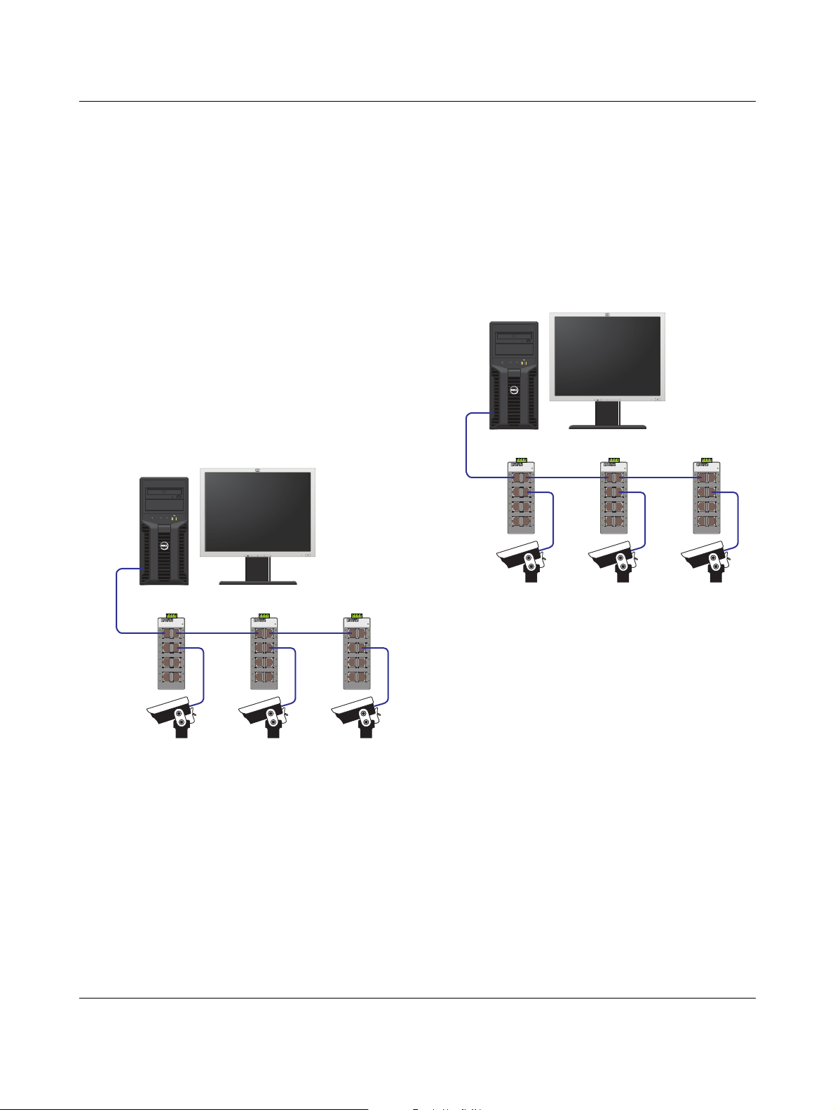
Example 1
Assuming gigabit devices are used with 9000-byte jumbo
frames and a total of three cascaded switches. Each switch
has one 8 bit/pixel camera plus 10 Mbps of miscellaneous
traffic from other ports.
Figure 14 depicts an example with three cameras
connected to individual switches. Each camera is
configured for an 8 bits per pixel color depth, creating a
load of 182 Mbps per camera (see Table 2) with a total
traffic load of 546 Mbps. Frame size is configured to 9000
bytes creating an overhead of 180 Mbps (see Figure 13) for
each cascading switch for a total of 360 Mbps.
1234
PowerEdgePowerEdge
T110
Example 2
To take advantage of the bandwidth not used in example 1,
assume one of the cameras is now required to operate at
12 bits per pixel.
The increased camera color depth increases the traffic load
to a total of 639 Mbps. Combined with the 360 Mbps
overhead with a 9000-byte frame size, the total bandwidth is
999 Mbps. While technically within the capability of a
1000 Mb switch, any additional traffic across the
transmission line could result in frame loss.
1234
PowerEdgePowerEdge
T110
HP LP 2065
FL SWITCH SFN 8TX
Ord.-No.:2891929
US
LNK/
LNK/
T
ACT
AC
X1
X2
100
100
LNK/
LNK/
T
AC
ACT
X3
X4
100
100
K/
LN
LNK/
T
T
AC
AC
X5
X6
100
100
LNK/
LNK/
T
ACT
AC
X7
X8
100
100
_
input+
auto
FL SWITCH SFN 8TX
Ord.-No.:2891929
US
LNK/
LNK/
T
T
AC
AC
X1
X2
100
100
LNK/
LNK/
T
T
AC
AC
X3
X4
100
100
LNK/
LNK/
T
AC
ACT
X5
X6
100
100
LNK/
LNK/
T
ACT
AC
X7
X8
100
100
FL SWITCH SFN 8TX
Ord.-No.:2891929
US
LNK/
LNK/
T
ACT
AC
X1
X2
100
100
LNK/
LNK/
T
ACT
AC
X3
X4
100
100
K/
LN
LNK/
T
AC
ACT
X5
X6
100
100
LNK/
LNK/
T
T
AC
AC
X7
X8
100
100
HP LP 2065
FL SWITCH SFN 8TX
Ord.-No.:2891929
US
LNK/
LNK/
T
ACT
AC
X1
X2
100
100
LNK/
LNK/
T
AC
ACT
X3
X4
100
100
K/
LN
LNK/
T
T
AC
AC
X5
X6
100
100
LNK/
LNK/
T
ACT
AC
X7
X8
100
100
_
input+
auto
FL SWITCH SFN 8TX
Ord.-No.:2891929
US
LNK/
LNK/
T
T
AC
AC
X1
X2
100
100
LNK/
LNK/
T
T
AC
AC
X3
X4
100
100
LNK/
LNK/
T
AC
ACT
X5
X6
100
100
LNK/
LNK/
T
ACT
AC
X7
X8
100
100
FL SWITCH SFN 8TX
Ord.-No.:2891929
US
LNK/
LNK/
T
ACT
AC
X1
X2
100
100
LNK/
LNK/
T
ACT
AC
X3
X4
100
100
K/
LN
LNK/
T
AC
ACT
X5
X6
100
100
LNK/
LNK/
T
ACT
AC
X7
X8
100
100
Figure 14 9000-byte frame size example
Adding the camera data and overhead together indicates a
total traffic load of 906 Mbps, leaving 94 Mbps of the
1000 Mbps total unused.
Figure 15 8000-byte frame size example
One possible solution is to change the frame size to
8000 bytes, reducing the overhead (see Figure 15). The
reduced frame size results in a total overhead of 320 Mbps.
Combined with the camera traffic load, the resulting
bandwidth requirement is 959 Mbps, allowing some space
for additional traffic.
2732_en_D 13
PHOENIX CONTACT GmbH & Co. KG • 32823 Blomberg • Germany • Phone: +49-(0) 5235-3-00
PHOENIX CONTACT • P.O.Box 4100 • Harrisburg • PA 17111-0100 • USA • Phone: +717-944-1300
www.phoenixcontact.com
 Loading...