

Page 1
Supple
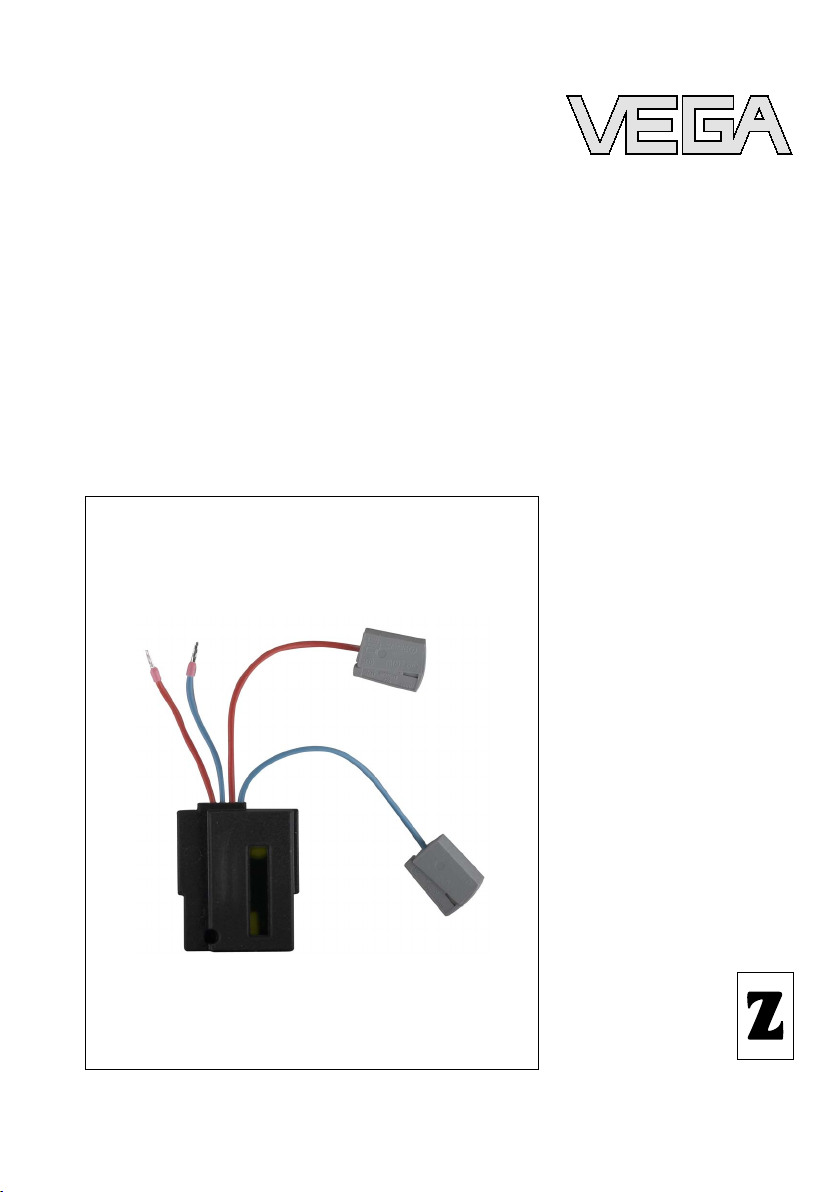
Filter element
mentary instructions
Page 2

Content
tent
Con
1 About this document
1.1 Function .
1.2 Target group . . . . . . . . . . . . . . . . . . . . . . . . . .
1.3 Symbolism used . . . . . . . . . . . . . . . . . . . . . . .
2 For your safety
2.1 Authorised personnel. . . . . . . . . . . . . . . . . . . .
2.2 Appropriate use. . . . . . . . . . . . . . . . . . . . . . . .
2.3 Safety instructions for Ex areas . . . . . . . . . . . .
2.4 Environmental instructions . . . . . . . . . . . . . . . .
3 Product description
3.1 Configuration. . . . . . . . . . . . . . . . . . . . . . . . . .
3.2 Principle of operation . . . . . . . . . . . . . . . . . . . .
3.3 Storage and transport . . . . . . . . . . . . . . . . . . .
4 Mounting
4.1 Prepare electronics . . . . . . . . . . . . . . . . . . . . .
4.2 Mount filter element . . . . . . . . . . . . . . . . . . . . .
5 Connecting to power supply
5.1 Preparing the connection . . . . . . . . . . . . . . . . .
5.2 Connection procedure . . . . . . . . . . . . . . . . . . .
. . . . . . . . . . . . . . . . . . . . . . . . . . . .
3
3
3
4
4
4
4
5
5
5
7
7
9
9
6 Setup
6.1 Setup . . . . . . . . . . . . . . . . . . . . . . . . . . . . . . .
7 Supplement
7.1 Technical data. . . . . . . . . . . . . . . . . . . . . . . . .
2 Filter
10
11
35028-EN-080619
element
Page 3
out this document
Ab
1 Abo
ut this document
1.1 Function
This
supplementary manual, together with the attached
operating instructions manual, has all the information you need
for quick setup and safe operation. Please read this manual
before you start setup.
1.2 Target group
This operating instructions manual is directed to trained
personnel. The contents of this manual should be made
available to these personnel and put into practice by them.
1.3 Symbolism used
Information, tip, no
This symbol indicates helpful additional information.
Caution: If
malfunctions can result.
Warning: If this warning is ignored, injury to persons and/or
serious damage to the instrument can result.
Danger: If this warning is ignored, serious injury to persons
and/or destruction of the instrument can result.
applications
Ex
This symbol indicates special instructions for Ex applications.
this warning is ignored, faults or
te
35028-EN-080619
Filter
l List
The dot set in front indicates a list with no implied sequence.
à Action
This
arrow
indicates a single action.
1 Sequence
Numbers set
element 3
in front indicate successive steps in a procedure.
Page 4

your safety
For
2 For
your safety
2.1 Authorised personnel
All
operations described in this operating instructions manual
must be carried out only by trained specialist personnel
authorised by the plant operator.
During work on and with the device the required personal
protection equipment must always be worn.
2.2 Appropriate use
The filter element to the electronics is part of a sensor.
2.3 Safety instructions for Ex areas
Please note the Ex-specific safety information for installation
and operation in Ex areas. These safety instructions are part of
the operating instructions manual and come with the Exapproved instruments.
2.4 Environmental instructions
Protection of the environment is one of our most important
duties. That is why we have introduced an environment
management system with the goal of continuously improving
company environmental protection. The environment management system is certified according to DIN EN ISO 14001.
Please help us fulfil this obligation by observing the environmental instructions in this manual:
l Chapter "Storage and
l Chapter "Disposal"
transport"
4 Filter
35028-EN-080619
element
Page 5

Produc
t description
Scope of delivery
Application range
3 Prod
3.1 Configurat
uct description
ion
The scope of delivery encompasses:
l Filter element
l Documentation
- This
supplementary instruction
3.2 Principle of operation
Power supply units that do not correspond to the current
electrical standard, often have an insufficient smoothing of the
voltage. When the caused residual ripple is too high for a
reliable operation, this is recognized by the internal energy
management of the sensor.
The sensor remains at a current value of 3.6 mA.
With the filter element, the sensor can be used also in systems
with high residual ripple.
The filter
approval.
Warning:
The filter
SIL.
element must not be mounted in systems with Ex
element must not be mounted in systems rated with
Packaging
35028-EN-080619
Filter
l The filter element cannot be used in combination with a
heating
l No HART signal can be transmitted when the filter elment
for the indicating and adjustment module.
is mounted
3.3 Storage and transport
Your instrument was protected by packaging during transport.
Its capacity to handle normal loads during transport is assured
by a test according to DIN EN 24180.
The packaging of standard instruments consists of environ-
ment-friendly, recyclable cardboard. For special versions, PE
foam or PE foil is also used. Dispose of the packaging material
via specialised recycling companies.
element 5
Page 6

Produ
ct description
Storage and transport
temperature
l Storage and transport temperature see "Supplement -
Technical data - Ambient conditions"
l Relative humidity 20 … 85 %
6 Filter
35028-EN-080619
element
Page 7

Mounting
Mounting steps
Mounting steps
4 Mou
4.1 Prepare
Proceed as follows:
1 Switch off power supply
2 Unscrew housing cover of the electronics compartment
3 Remove the indicating and adjustment module, in case one
4 Disconnect the connection cables of the supply voltage on
nting
electronics
is installed
the eletronics module (terminals 1 and 2)
4.2 Mount filter element
Proceed as follows:
1 Plug the filter element onto the oscillator
35028-EN-080619
Filter
element 7
Page 8

2
1
3
Moun
ting
Fig. 1: Mounting
1 Filter element
2 Output of the filter element to the oscillator
3 Terminals for voltage supply
of the filter element
2 Connect the two short connection cables (2) to the
oscillator
Red = plus (terminal 1)
Blue = minus (terminal 2)
See also chapter "Connecting to power supply"
3 Connect long connection cables (3) to the sensor supply
lines
See chapter "Connecting to power supply"
8 Filter
35028-EN-080619
element
Page 9

I²C
Display
1
2
1 2 5
6 7 8
ecting to power supply
Conn
5 Con
5.1 Preparin
necting to power supply
g the connection
Follow the instructions in the operating instructions manual of
the sensor.
5.2 Connection procedure
Fig. 2: Wiring
1 Voltage supply/Signal output
2 Filter element
plan
35028-EN-080619
Filter
1 Connect the plus cable of the power supply to the terminal
of the red connection cable
2 Connect the minus cable of the power supply to the
terminal of the blue connection cable
3 Insert the plug connector into the excavation in front of the
oscillator
4 Press the indicating and adjustment module (1) onto the
electronics and turn it to the right until it snaps in.
element 9
Page 10

Setup
6 Setup
6.1 Setup
Setup is carried out according to the operating instructions
manual of the respective sensor.
After mounting, the filter element is immediately ready and
must not be activated.
10 Filter
35028-EN-080619
element
Page 11

Sup
plement
7 Sup
7.1 Technical
Technical data
All technical data are listed in the operating instructions manual of the respective
sensor.
plement
data
35028-EN-080619
Filter
element 11
Page 12

VEGA Grieshaber KG
ISO 9001
Am Hohenstein 113
77761 Schiltach
Germany
Phone +49 7836 50-0
Fax +49 7836 50-201
E-mail: info@de.vega.com
www.vega.com
Printing date:
statements concerning scope of delivery, application,
All
practical use and operating conditions of the sensors and
processing systems correspond to the information avail-
able at the time of printing.
© VEGA Grieshaber KG, Schiltach/Germany 2008
Subject to change without prior notice 35028-EN-080619
 Loading...