

Page 1

MANUAL
FIELDBARRIER
PROCESS AUTOMATION
Page 2

FIELDBARRIER
With regard to the supply of products, the current issue of the following document is applicable: The General Terms of Delivery for Products and Services of the Electrical Industry,
published by the Central Association of the Electrical Industry (Zentralverband Elektrotechnik und Elektroindustrie (ZVEI) e.V.) in its most recent version as well as the supplementary
clause: "Expanded reservation of proprietorship"
Page 3

FieldBarrier
1 Introduction ..............................................................................................3
2 Validity of these instruction manual ......................................................4
3 Symbols used ...........................................................................................5
4 Instruction manual ...................................................................................6
4.1 Intended use ............................................................................................................ 6
4.2 Marking .................................................................................................................... 7
4.3 Ambient conditions ................................................................................................ 7
4.4 Mounting and dismounting .................................................................................... 7
4.4.1 Mounting and dismounting the F2D0-FB-Ex4.*** ..................................................... 7
4.4.2 Mounting/dismounting of RD0-FB-Ex4 ..................................................................... 7
4.5 Commissioning and installation ........................................................................... 8
4.5.1 Commissioning and installation of the F2D0-FB-Ex4.*** .......................................... 9
4.5.2 Commissioning and installation of RD0-FB-Ex4 ..................................................... 10
4.6 Grounding / shielding of the F2D0-FB-Ex4.*** and RD0-FB-Ex4 ...................... 10
4.7 Repair and maintenance ...................................................................................... 11
4.8 Fault elimination ................................................................................................... 11
4.9 Disposal ................................................................................................................. 11
5 General ....................................................................................................12
5.1 Range of application of the FieldBarrier ............................................................ 12
5.2 Introduction to intrinsic safety for fieldbus systems ........................................ 12
5.2.1 The FISCO model ................................................................................................... 13
5.2.2 The Entity model ..................................................................................................... 14
5.2.3 Topologies .............................................................................................................. 15
5.2.4 Grounding ............................................................................................................... 17
6 Planning for a fieldbus application ......................................................19
6.1 Functional description of the FieldBarrier ......................................................... 19
6.2 Topologies in combination with the FieldBarrier .............................................. 21
6.2.1 Topologies on intrinsically safe outputs .................................................................. 21
6.2.2 Topologies of the trunk in connection with the FieldBarrier .................................... 22
6.3 Dimensioning of a fieldbus segment .................................................................. 23
6.4 Terminating the trunk with a fieldbus terminating resistor. ............................. 23
6.5 Mechanical dimensions ....................................................................................... 24
6.5.1 Mechanical dimensions of the R version ................................................................ 25
08/2007 122329
Subject to reasonable modifications due to technical advances. Copyright Pepperl+Fuchs, Printed in Germany
Pepperl+Fuchs Group • Tel.: Germany +49 621 776-0 • USA +1 330 4253555 • Singapore +65 67799091 • Internet http://www.pepperl-fuchs.com
1
Page 4

FieldBarrier
7 Commissioning the FieldBarrier .......................................................... 26
7.1 Mounting FieldBarriers ......................................................................................... 26
7.1.1 Mounting the FieldBarrier F*D0-FB-Ex4.*** ........................................................... 26
7.1.2 Handling F*D0-FB-Ex4.CG cable glands ................................................................27
7.1.3 Handling the F*D0-FB-Ex4.CGB and F*D0-FB-Ex4.CGS cable gland ................... 28
7.1.4 Handling the F*D0-FB-Ex4.CGAB cable gland .......................................................29
7.1.5 Mounting the stop plug ............................................................................................ 30
7.1.6 Mounting the FieldBarrier RD0-FB-Ex4 ..................................................................30
7.2 FieldBarrier connections ...................................................................................... 30
7.3 Grounding .............................................................................................................. 31
7.4 Fieldbus termination ............................................................................................. 31
7.5 Displays and error messages. ............................................................................. 32
Subject to reasonable modifications due to technical advances. Copyright Pepperl+Fuchs, Printed in Germany
2
Pepperl+Fuchs Group • Tel.: Germany +49-621-776-0 • USA +1-330-4253555 • Singapore +65-67-799091 • Internet www.pepperl-fuchs.com
08/2007 122329
Page 5
1 Introduction
The FieldBarrier F*D0-FB-Ex4.*** and RD0-FB-Ex4 connect up to 4 intrinsically safe
field devices. It is connected via non-intrinsically safe connections to the trunk of a
fieldbus with a physical layer in accordance with IEC 61158-2.
The FieldBarrier works exclusively on the physical layer, which makes it independent
of the protocol. This allows it to be substituted for any field bus with a physical layer
in accordance with IEC 61158-2. This includes the FOUNDATION fieldbus and the
PROFIBUS MBP, for example.
More recent documentation also refers to PROFIBUS MBP in connection with PROFIBUS PA. MBP stands for Manchester Bus powered.
PROFIBUS PA and PROFIBUS MBP are identical. The following section refers only to the term PROFIBUS MBP that has just been introduced.
PROFIBUS MBP-IS refers to the intrinsically safe version of the
PROFIBUS MBP.
The trunk of the fieldbus can be supplied via additional terminals to other FieldBarriers
(cascading) or other fieldbus stations.
If the trunk is mounted in increased safety, the FieldBarrier can be mounted in the
Zone 1 and Zone 22 (non-conductive dust) of a hazardous area. The terminals for the
trunk are designed in increased safety EEx e.
If the FieldBarrier is the last device connected to the trunk, it must be terminated with
a fieldbus terminator. A fieldbus terminator is integrated into the FieldBarrier for this
purpose, and can be turned on when it is needed.
The trunk is galvanically separated from the outputs. 40 mA per output is available for
the intrinsically safe power supply of the field devices. The number of field devices
that can actually be operated on an output depends on their power consumption.
The line length per output can be up to 120 m and is operated without a fieldbus terminator. The outputs correspond to the requirements of PTB Report W-53 (FISCO
Model.) For additional information on this subject, please refer to chapter 5.2.1
Each output has a voltage and current limit. This prevents the entire fieldbus segment
from failing if a fault occurs on just one output.
The technical data can be found in the data sheet.
FieldBarrier
08/2007 122329
Subject to reasonable modifications due to technical advances. Copyright Pepperl+Fuchs, Printed in Germany
Pepperl+Fuchs Group • Tel.: Germany +49 621 776-0 • USA +1 330 4253555 • Singapore +65 67799091 • Internet http://www.pepperl-fuchs.com
3
Page 6
FieldBarrier
2 Validity of these instruction manual
This instruction manual descibes the following Pepperl+Fuchs products:
• the FieldBarrier F2D0... for panel mounting in aluminum field housings.
• The FieldBarrier RD0... for mounting on a 35-mm top hat section rail in accordance
with EN 50 022.
A corresponding declaration of conformity may be requested from the
manufacturer.
The manufacturer of the product, Pepperl+Fuchs GmbH in D-68301 Mannheim, has
a certified quality assurance program in accordane with ISO 9001.
ISO9001
Subject to reasonable modifications due to technical advances. Copyright Pepperl+Fuchs, Printed in Germany
4
Pepperl+Fuchs Group • Tel.: Germany +49-621-776-0 • USA +1-330-4253555 • Singapore +65-67-799091 • Internet www.pepperl-fuchs.com
08/2007 122329
Page 7
3 Symbols used
This symbol warns of a danger.
In the event the warning is ignored, the consequences may range from
personal injury to death or from damage to equipment to destruction.
This symbol warns of a possible fault.
Failure to observe the instructions given in this warning may result in
the device and any facilities or systems connected to it developing a
fault or even failing completely.
This symbol draws your attention to important information.
FieldBarrier
08/2007 122329
Subject to reasonable modifications due to technical advances. Copyright Pepperl+Fuchs, Printed in Germany
Pepperl+Fuchs Group • Tel.: Germany +49 621 776-0 • USA +1 330 4253555 • Singapore +65 67799091 • Internet http://www.pepperl-fuchs.com
5
Page 8

FieldBarrier
4 Instruction manual
These instructions apply in conjunction with the respective data sheets. You can access the data sheets at www.pepperl-fuchs.com
The operator of the system bears the responsibility in terms of planning,
mounting, commissioning, operation and maintenance, especially in
conjunction with applications in areas subject to the danger of explosion.
The data sheet lists the electrical characteristics of the EC declaration of conformity
and is considered and integral part of the instruction manual.
4.1 Intended use
The FieldBarrier serves as a galvanic isolation between intrinsically safe and non-intrinsically safe fieldbuses.
The FieldBarrier can be used for all fieldbus systems using "Manchester Coding Bus
Powered“ physical layout in accordance with IEC 61158-2.
The inputs of the field FieldBarrier are designed in the "Increased safety“ ignition protection method. The outputs of the FieldBarrier are designed in the "Intrinsic Safety“
ignition protection method and make it possible to operate intrinsically safe field devices.
Data sheets for FieldBarriers contain the electrical data of the EC declaration of conformity and are considered an integral part of the instruction manual.
The FieldBarrier may be installed in hazardous areas of category 2G / Zone 1 and
Zone 22 (non-conductive dust).
FieldBarriers that are operated in general electrical systems must not
thereafter be operated in electrical systems that are connected with
hazardous areas.
.
Laws and/or regulations governing the use or intended usage goal must be observed.
FieldBarriers are only approved for proper professional usage in accordance with the
intended purposes. Improper handling will void any claim made under the warrantee
and any manufacturer's liability.
Protection of operating personnel and the system is not ensured if the
module is not used in accordance with its intended purpose.
The device can only be operated by trained professionals in accordance with the
available instruction manual.
Subject to reasonable modifications due to technical advances. Copyright Pepperl+Fuchs, Printed in Germany
6
Pepperl+Fuchs Group • Tel.: Germany +49-621-776-0 • USA +1-330-4253555 • Singapore +65-67-799091 • Internet www.pepperl-fuchs.com
08/2007 122329
Page 9

4.2 Marking
FieldBarriers are identified by:
FieldBarrier F2D0-... FieldBarrier RD0-...
Pepperl + Fuchs Pepperl + Fuchs
D-68307 Mannheim D-68307 Mannheim
F2D0-FB-Ex*.*** RD0-FB-Ex*.***
PTB 02 ATEX 2086 PTB 02 ATEX 2086
¬ II 2 (1 G/D) G Ex me [ia] IIC T4 ¬ II 2 (1 G/D) G Ex me [ia] IIC T4
¬ Ex tD A22 IP54 T135 °C
(non-conductive dust)
4.3 Ambient conditions
For the ambient temperature range, please refer to the respective data sheet.
4.4 Mounting and dismounting
Commissioning and installation must only be performed by specialist who are trained
specifically for this purpose.
Recognized rules of the technology and setup requirements must be maintained during mounting and dismounting. Especially for tasks on electrical systems, special
safety requirements must be observed. Special attention must be paid to the following
points:
1. Has the FieldBarrier been installed in accordance with specifications?
2. Is the FieldBarrier free of damage?
4.4.1 Mounting and dismounting the F2D0-FB-Ex4.***
The housing of FieldBarrier F2D0-FB-Ex4.*** is designed in protection class IP 67. It
is intended for panel mounting. 2 screws with a diameter of 6 mm should be used for
mounting.
The mounting material should be selected according to the nature of the sub-surface
(the wall). When selecting mounting material, care must be taken that it will ensure a
secure fastening. The torque to be used for the mounting screws depends on the
screws being used.
Type F*D0-FB-Ex4.CG should be mounted so that the cable glands are protected
from the effects of mechanical hazards.
The cover screws of the FieldBarrier should be tightened with a torque of 2.5 Nm.
4.4.2 Mounting/dismounting of RD0-FB-Ex4
FieldBarrier RD0-FB-Ex4 is designed for mounting on a 35-mm DIN rail in accordance
with EN 50 022. It must be mounted in a housing that corresponds to at least protection class IP 54. The housing must also have an EC declaration of conformity in accordance with EC 94/9.
FieldBarrier
08/2007 122329
Subject to reasonable modifications due to technical advances. Copyright Pepperl+Fuchs, Printed in Germany
Pepperl+Fuchs Group • Tel.: Germany +49 621 776-0 • USA +1 330 4253555 • Singapore +65 67799091 • Internet http://www.pepperl-fuchs.com
7
Page 10
FieldBarrier
4.5 Commissioning and installation
The FieldBarrier may be installed according to its designation in Zones 1 and Zone 22
(non-conductive dust) .
The Declaration of conformity must be observed. It is especially impor-
tant to maintain any "Special conditions" that may be indicated.
When installing intrinsically safe fieldbus segments, EN 60079-14/IEC 60079-14 must
be observed. For the Federal Republic of Germany, the "National Foreword“ of DIN
EN 60079-14/VDE 0165 Part 1 must also be observed.
When using the outputs designated intrinsically safe in Dust-Ex range
"D", only field devices certified for this purpose may be connected.
When connecting intrinsically safe field devices with the FieldBarrier,
the highest level of explosion protection should be considered (Proof of
Intrinsic Safety).
The switch for the internal bus termination can be activated even during operation.
The following identifying values must be observed when connecting fieldbus transmission lines:
• For the cable parameters to be observed, please refer to chapter 5.2.1
• The insulating length of the wire is 9 mm
• Wire cross-section 0.2 mm² to 2.5 mm² or AWG 24 to 14
• Whenever finely stranded conductors must be used, the strand ends must be protected from fraying, for example by using end splices.
• Tightening torque of the screw terminals (if present) 0. 4... 0.5 Nm
• Tightening torque of the screwed connections of cable glands for FieldBarriers
F2D0...
The tightening torques of the slotted nuts depend on the cable used and must
therefore be determined by the user. The cap nuts must be securely tightened.
Tightening the cap nuts too tight can have a negative effect on the protection class.
The following figures should be taken as rough guides:
Type Cap nut Lower part
F2D0-FB-Ex4.CG 2.5 Nm 3.75 Nm
F2D0-FB-Ex4.CGB 4.17 Nm 6.25 Nm
F2D0-FB-Ex4.CGS 4.17 Nm 6.25 Nm
F2D0-FB-Ex4.CGAB 22 Nm 28 Nm
A fieldbus transmission line with an insulation voltage between the bus line and shield
of at least 500 V must be used for intrinsically safe fieldbus segments.
Subject to reasonable modifications due to technical advances. Copyright Pepperl+Fuchs, Printed in Germany
8
Pepperl+Fuchs Group • Tel.: Germany +49-621-776-0 • USA +1-330-4253555 • Singapore +65-67-799091 • Internet www.pepperl-fuchs.com
08/2007 122329
Page 11
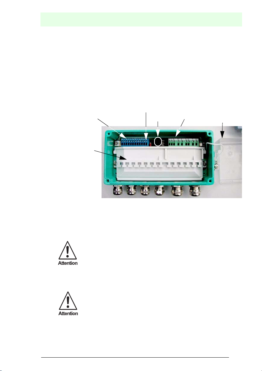
4.5.1 Commissioning and installation of the F2D0-FB-Ex4.***
Only permanently laid cables and lines must be inserted into the cable glands.
The screw plugs must only be replaced by cable glands who are adapted for the intended kind of use. By mounting the cable glands pay attention to the according instruction manual.
For the permissible cable diameters, please refer to the respective data sheet. The
operator must provide an appropriate strain-relief clamp (for example with a suitable
cable clamp). The mounting notes in chapter 4.4 must be observed.
FieldBarrier
Connections for
intrinsically safe
fieldbus segments
Switches for the
internal bus connection
LEDs
Connections for the
non-intrinsically safe
fieldbus
Cover
Fastening options
for connection cables
by using cable ties
Cable gland for the
intrinsically safe
fieldbus segments
Cable gland for the
non-intrinsically safe
fieldbus
Cable glands that are not in use must be closed off with a corresponding stop plug or
replaced by an appropriate screw plug. Stop plugs and screw plugs must have an EC
declaration of conformity.
The ambient temperature range can be restricted by the stop plug.
By mounting the cable glands pay attention to the according instruction
manual.
For examples of stop plugs and screw plugs, please refer to the respective data
sheets.
In order to maintain the IP 67 protection class, all unused cable glands
(M16 and M20) must be plugged with a M20 blind plug.
For metallic housings in hazardous areas, a suitable potential equalization per EN 60
079 is required. A grounding screw is provided on the housing for this purpose. The
08/2007 122329
Subject to reasonable modifications due to technical advances. Copyright Pepperl+Fuchs, Printed in Germany
Pepperl+Fuchs Group • Tel.: Germany +49 621 776-0 • USA +1 330 4253555 • Singapore +65 67799091 • Internet http://www.pepperl-fuchs.com
9
Page 12

FieldBarrier
connection must be designed to prevent self locking and must be protected against
corrosion. Protection against corrosion can also be achieved by using tinned cable
plates, for example.
The cover of the non-intrinsically safe fieldbus connection must only be
removed when no electrical power is present.
The connection of the non-intrinsically safe fieldbus connection must
only be made when no electrical power is present. After that, the cover
must be remounted.
Before closing the cover, a visual inspection must be performed to ensure that there
are no visible signs of damage on the cover seal. In the event of damage, the seal
must be replaced by an original seal.
The screws on the cover should be tightened to a torque of 2.5 Nm.
4.5.2 Commissioning and installation of RD0-FB-Ex4
The FieldBarrier RD0-FB-Ex4 is mounted on a top-hat rail compliant with EN 50 022.
Connections for
intrinsically safe
fieldbus segments
Fastening options
for connection cables
by using cable ties
Switches for the
internal bus connection
LEDs
Connections for the
non-intrinsically safe
fieldbus under the
Cover
Cover
The cover of the non-intrinsically safe fieldbus connection must only be
removed when no electrical power is present.
The connection of the non-intrinsically safe fieldbus connection must
only be made when no electrical power is present. After that, the cover
must be remounted.
4.6 Grounding / shielding of the F2D0-FB-Ex4.*** and RD0-FB-Ex4
For the FieldBarrier F2D0*** the terminals PA and 1B are electrically connected to the
housing.
For the FieldBarrier RD0*** the terminals PA and 1B are electrically connected with
both metallic top-hat rail connectors.
The 5S and 6S shield connections of the non-intrinsically safe fieldbus segments are
connected internally through a capacitor less than or equal to 5.7 nF with the potential
Subject to reasonable modifications due to technical advances. Copyright Pepperl+Fuchs, Printed in Germany
10
Pepperl+Fuchs Group • Tel.: Germany +49-621-776-0 • USA +1-330-4253555 • Singapore +65-67-799091 • Internet www.pepperl-fuchs.com
08/2007 122329
Page 13

equalization (capacitive grounding of the shield of the trunk). This capacitor can be
bypassed with terminals 1B and 2B (hard grounding of the shield of the trunk).
If the shield of the EEx e fieldbus transmission line is grounded for reasons related to
EMC, Section 12.2.2.3 of EN 60079-14 and Section 3.3.3 of the PNO introductory
manual PROFIBUS PA or Sections 4.1 and 4.4 of the FOUNDATION Fieldbus Application Guides must always be observed.
Each shield connection of intrinsically safe fieldbus segments (12S, 15S, 18S, 21S)
is connected internally through a capacitor of less than 12 nF with the potential equalization (capacitive grounding of the shield of the fieldbus transmission line). The cable
that is used must be designed for an insulation voltage of at least 500 V between the
bus transmission line and the shield.
A hard grounding of the shielding of the intrinsically safe trunk can be implemented
with FieldBarriers of types F*D0-FB-Ex4.CGB, F*D0-FB-Ex4.CGS and F*D0-FBEx4.CGAB.
4.7 Repair and maintenance
The transmission behavior of the FieldBarrier is stable even over long periods of time.
There is thus no need for regular adjustments or similar tasks. Maintenance is therefore not required.
4.8 Fault elimination
FieldBarriers that are operated in connection with hazardous areas must not be modified. If there is a defect, the FieldBarrier must always be replaced.
Defective housing parts (for example cover seals) must be replaced only by original
parts. Tasks for eliminating malfunctions must only be performed by specialists who
are specially trained and authorized for the task.
FieldBarrier
4.9 Disposal
Disposal of the packaging and FieldBarrier must only take place in accordance with
the requirements of the country in which the FieldBarrier is installed.
The FieldBarrier does not contain any batteries that must be disposed of separately
from the FieldBarrier.
08/2007 122329
Subject to reasonable modifications due to technical advances. Copyright Pepperl+Fuchs, Printed in Germany
Pepperl+Fuchs Group • Tel.: Germany +49 621 776-0 • USA +1 330 4253555 • Singapore +65 67799091 • Internet http://www.pepperl-fuchs.com
11
Page 14

FieldBarrier
5 General
5.1 Range of application of the FieldBarrier
FieldBarriers can be used in combination with fieldbus systems that use the "Manchester Coding Bus Powered“ physical layout in accordance with IEC 61158-2. This
includes the H1 bus of the FOUNDATION fieldbus and the PROFIBUS MBP, for example. FieldBarriers ensure galvanic isolation between a non-intrinsically safe and an
intrinsically safe fieldbus segment.
Both the H1 bus of the FOUNDATION fieldbus and the PROFIBUS
MBP use the physical layout described above in accordance with IEC
61158-2. The FieldBarrier can be used for both systems. When the following section refers to the H1 bus, this should be understood to
include both the H1 bus of the FOUNDATION fieldbus and the PROFIBUS MBP!
The advantage of the transmission physics in accordance with IEC 61158-2 is that
power can be supplied to fieldbus stations from the transmission line. The supply current required for this is made available by power repeaters or power supply units for
FOUNDATION Fieldbus and by the segment coupler for the PROFIBUS MBP or
PROFIBUS MBP-IS, which is intrinsically safe version of the PROFIBUS MBP.
The following diagram illustrates a typical fieldbus structure in combination with FieldBarriers
Figure 5.1: Typical field bus structure of intrinsically safe applications
5.2 Introduction to intrinsic safety for fieldbus systems
If fieldbus systems are used in hazardous areas, the corresponding explosion protection measures must be taken. The Intrinsic Safety explosion protection method offers
Subject to reasonable modifications due to technical advances. Copyright Pepperl+Fuchs, Printed in Germany
12
Pepperl+Fuchs Group • Tel.: Germany +49-621-776-0 • USA +1-330-4253555 • Singapore +65-67-799091 • Internet www.pepperl-fuchs.com
08/2007 122329
Page 15

the advantage that fieldbus stations can be disconnected from or connected to the
transmission line during ongoing operation.
If a fieldbus segment is designed in Intrinsic Safety ignition protection type, proof of
intrinsic safety must be provided. To make this proof of Intrinsic Safety as simple as
possible, there are 2 different models:
• the FISCO model
• the Entity model
Which of the two following models should be used is stipulated by
national requirements and/or laws.
Both models are explained briefly below.
5.2.1 The FISCO model
The FISCO model was developed by the German Federal Physical Technical Institute
(PTB), which published information on it in Report PTB-W-53 "Examination of intrinsic
safety for fieldbus systems“. FISCO stands for Fieldbus Intrinsically Safe COncept
and is standardized in the IEC 60079-27. This model is based on the following prerequisites:
1. To transmit electrical power and data, the bus system uses the "Manchester Coding Bus Powered“ physical layout in accordance with IEC 61158-2. This is the case
for both the FOUNDATION fieldbus and the PROFIBUS MBP.
2. Only one active source is permitted on a bus segment (the power repeater/the segment coupler/the FieldBarrier). All other components work as passive current sinks.
3. The basic current consumption of a bus station is at least 10 mA.
4. For each bus device it must be ensured that:
.
5. Each bus station must fulfill the following requirement:
6. The permissible line length for EEx ia IIC applications is 1000 m.
7. The permissible spur length for Ex applications is 60 m per spur line. The definition
of the spur must be observed in this connection.
8. The transmission line that is used must conform to the following cable parameters:
Resistor coating: 15 Ω/km < R’ < 150 Ω/km
Inductance coating: 0.4 mH/Km <
Capacitance coating: 45 nF/km <
Taking the shield into consideration, the capacitance coating is calculated as follows:
C’ = C’
08/2007 122329
conductor/conductor
FieldBarrier
V
> Vo of the Segment coupler/power repeater/FieldBarrier
i
I
> Io of the Segment coupler/power repeater/FieldBarrier
i
P
> Po of the Segment coupler/power repeater/FieldBarrier
i
C
< 5 nF
i
L
< 10 µH
i
L’ < 1 mH/km
C’ < 200 nF/km (including the shield)
+ 0.5 * C’
conductor/shield
if the bus line is potential free or
Subject to reasonable modifications due to technical advances. Copyright Pepperl+Fuchs, Printed in Germany
Pepperl+Fuchs Group • Tel.: Germany +49 621 776-0 • USA +1 330 4253555 • Singapore +65 67799091 • Internet http://www.pepperl-fuchs.com
13
Page 16

FieldBarrier
C’ = C’
conductor/conductor
+ C’
conductor/shield
if the shield is connected with a pole of
the segment coupler/Power Link.
9. The bus segment must be terminated on both ends of the trunk with a fieldbus terminator. The fieldbus terminator must conform to the following limits:
90 Ω <
R < 100 Ω
0 µF <
C < 2.2 µF:
Given the prerequisite that Points 1 through 9 are all satisfied, Proof of Intrinsic Safety
has been provided by means of the FISCO model. Points 1, 3 and 5 are automatically
satisfied if a product is certified in accordance with the FISCO model.
A condition for granting the Proof of Intrinsic Safety according to the
FISCO model is that the power source used, here the segment coupler,
power repeater, or FieldBarrier , and all field devices must be certified in
accordance with the FISCO model.
Furthermore, the cable must meet the requirements of the FISCO
model.
For the characteristic Ex values, please refer to the respective EC Declaration of conformity.
5.2.2 The Entity model
The Entity model is based on the observation that the cable represents concentrated
inductance and capacitance. The result is that in comparison with the FISCO model
less electrical power can be transmitted into the hazardous area. Typical values here
are in the vicinity of 10.6 V and 70 mA. As a result,
• fewer stations can be operated on a fieldbus segment
• maximum possible cable lengths are lower than for the FISCO model:
The items 1 through 9 enumerated in chapter 5.2.1 also apply to the Entity model, with
the exception of item 5. According to the Entity model, the internal inductance of a
field device must be <
20 µH and its internal capacitance must be < 5 nF.
For the Proof of Intrinsic Safety according to the the Entity model, it must also be determined for comparison of voltages, currents and outputs that the inductances and
capacitances connected to the FieldBarrier do not exceed the maximum permissible
values L
and C0. The following rule applies in general:
0
> L
cable
cable
+ Σ L
+ ΣC
i
i
L
0
C0 > C
Subject to reasonable modifications due to technical advances. Copyright Pepperl+Fuchs, Printed in Germany
14
Pepperl+Fuchs Group • Tel.: Germany +49-621-776-0 • USA +1-330-4253555 • Singapore +65-67-799091 • Internet www.pepperl-fuchs.com
08/2007 122329
Page 17

5.2.3 Topologies
Fieldbus topologies are independent of whether an H1 fieldbus segment of the
FOUNDATION fieldbus or a PROFIBUS MBP segment is being operated.
PROFIBUS MBP(-IS)
PROFIBUS DP
or H1 bus of the
FOUNDATION
or H1 bus (IS) of the
FOUNDATION
fieldbus
fieldbus
Trunk
Segment coupler
or
Power repeater
Spur
Spur
The basic layout of a fieldbus with FieldBarriers is illustrated in Figure 5.1.
The use of FieldBarriers influences possible topologies. For more
detailed information, please refer to chapter 6.2.
FieldBarrier
Bus termination
resistor
Spur
Two cable types with the following components are essentially recommended for both
fieldbus systems:
Type A Type B
Cable structure twisted wire
pair, shielded
Conductor cross-section (nominal) 0.8 mm²
One or more twisted
pairs, total shielding
0.32 mm² (AWG 22)
(AWG 18)
Loop resistor (direct current) 44 Ω/km 112 Ω/km
Wave resistance at 31.25 kHz 100 Ω + 20% 100 Ω + 30%
Wave attenuation at 39 kHz 3 dB/km 5 dB/km
Capacitive asymmetry 2 nF/km 2 nF/km
Group runtime distortion (7.9 ... 39) kHz 1.7 µs
Covering level of the shield 90%
Maximum extent of the network for non-
1900 m 1200 m
a
a
intrinsically safe applications
Maximum extent of the network for intrinsi-
1000 m
a
cally safe applications
08/2007 122329
a. not specified
Subject to reasonable modifications due to technical advances. Copyright Pepperl+Fuchs, Printed in Germany
Pepperl+Fuchs Group • Tel.: Germany +49 621 776-0 • USA +1 330 4253555 • Singapore +65 67799091 • Internet http://www.pepperl-fuchs.com
15
Page 18

FieldBarrier
The recommended network expansion is equal to the sum of the trunk and all spurs.
A fieldbus station works from an input voltage of 9 V, i. e. this value corresponds to
the minimum input voltage.
Please note the specifications of the FieldBarrier. For more detailed
information, please refer to chapter 6.3.
With an unfavorable distribution of stations, i.e. if all fieldbus stations are widely removed from the segment coupler/power repeater, it can happen that the voltage drop
along the line is so great that the voltage level at the end is insufficient. This results in
a shortening of the transmission line or the necessity of using cable with a larger
cross-section. Under unfavorable conditions, the following lengths can be achieved
with cable type A (0.8 mm² or AWG 18):
• Application EEx ia IIC ==> 860 m
• Non-Ex application ==> 852 m
The fieldbus allows for spurs. The length of each spur is determined by the number
of fieldbus stations, the number of field devices per spur and the range of application.
The following table shows an overview:
Number of
communication
members
1 to 12 120 m 90 m 60 m 60 m
13 to 14 90 m 60 m 30 m 1 m
15 to 18 60 m 30 m 1 m 1 m
19 to 24 30 m 1 m 1 m 1 m
25 to 32 1 m 1 m 1 m 1 m
Maximum spur length for non-Ex applications
1 device per
spur
2 devices per
spur
3 devices per
spur
4 devices per
spur
Please note that the permissible total line length (the total of the trunk
and all spurs) must not be exceeded.
For Ex applications the spur length is limited to 60 m per spur.
For cable type B, multiple fieldbus segments can be carried in one cable. If other types
of cable than those recommended are used, the permissible line lengths are reduced.
Subject to reasonable modifications due to technical advances. Copyright Pepperl+Fuchs, Printed in Germany
16
Pepperl+Fuchs Group • Tel.: Germany +49-621-776-0 • USA +1-330-4253555 • Singapore +65-67-799091 • Internet www.pepperl-fuchs.com
08/2007 122329
Page 19

FieldBarrier
Following values applies especially for the FieldBarrier:
The maximum cable length per output is limited to 120 meter and may be operated
without terminators. The outputs meet the requirements of the IEC 60079-27.
Number of
communication members
Maximum spur length
1 device per output
1 to 12 120 m
13 to 14 90 m
15 to 18 60 m
Consider the master of the PROFIBUS Segment Coupler or the host
card at FOUNDATION Fieldbus installations as communication members.
Use the free Segment Checker software to create topologies containing
FieldBarriers (www.segmentchecker.com).
5.2.4 Grounding
The cable types described in the previous section, which are recommended for both
fieldbus systems, have a shield. For reasons of EMC protection, the shield should be
grounded. There are essentially two different ways in which this is possible:
• Double-sided hard grounding of the shield (connection between the shield and potential equalization
• Capacitive grounding on one end of the shield (connection of the shield to the potential equalization via a capacitor) and hard grounding on the other end
• Hard grounding on one end of the shield and no grounding on the other end
The best EMC protection is achieved with grounding on both ends of the shield. In this
case, a potential equalization conductor is required.
If capacitive grounding on one end is used, there is no need for the potential equalization conductor for non-Ex applications. However, the EMC protection is not as good
as when the shield is applied on both sides.
If there is a transition from the hazardous area to the safe area with capacitive grounding the capacitor must meet the following requirements:
• It must have a solid dielectric, for example ceramic
•C < 10 nF
• Test voltage >
1500 V
A capacitor which meets the above requirements is integrated into each
output in the FieldBarrier. An additional capacitor is not required.
08/2007 122329
Subject to reasonable modifications due to technical advances. Copyright Pepperl+Fuchs, Printed in Germany
Pepperl+Fuchs Group • Tel.: Germany +49 621 776-0 • USA +1 330 4253555 • Singapore +65 67799091 • Internet http://www.pepperl-fuchs.com
17
Page 20

FieldBarrier
If the shield is only applied on one side, EMC protection is less reliable. In this case
as well, there is no need for the potential equalization conductor in the case of non Ex
applications.
Pepperl+Fuchs always recommends the use of shielded lines for the
fieldbus. The shield should be hard grounded on the segment coupler/
Power Repeater, FieldBarrier and on all field devices. Please note in
this regard chapter 4.6.
For intrinsically safe applications, a potential equalisation between the
hazardous and the safe area is required. Note in this regard the respective relevant setup requirements.
If there is no potential equalisation between the hazardous and the safe
area, there is a possibility of capacitive grounding on the segment coupler/Power Repeater or FieldBarrier.
The capacitor used must have a fixed dielectric. For the capacitance of
the capacitor, the following applies: C <
must be designed for a test voltage of >
10 nF. In addition, the capacitor
1500 V.
Subject to reasonable modifications due to technical advances. Copyright Pepperl+Fuchs, Printed in Germany
18
Pepperl+Fuchs Group • Tel.: Germany +49-621-776-0 • USA +1-330-4253555 • Singapore +65-67-799091 • Internet www.pepperl-fuchs.com
08/2007 122329
Page 21

6 Planning for a fieldbus application
The following section explains how to perform planning for a fieldbus application in
combination with the FieldBarrier. This planning is different in a few items
• from planning without a FieldBarrier
• depending on whether a FOUNDATION fieldbus or a PROFIBUS MBP application
is being planned.
Explicit mention is made of this in the corresponding places.
6.1 Functional description of the FieldBarrier
The FieldBarrier is used to connect up to 4 intrinsically safe fieldbus stations. It is connected over non-intrinsically safe connections (trunk) with a field device using the
"Manchester Coding Bus Powered“ physical layout per IEC 61158-2. The trunk of the
fieldbus can be supplied via additional terminals to other FieldBarriers (cascading) or
other fieldbus stations.
Up to 4 FieldBarriers can be connected to one fieldbus segment.
The FieldBarrier carries out the following tasks:
• Ensuring intrinsic safety on the outputs
• Ensuring galvanic isolation between the non-intrinsically safe fieldbus segment
(trunk) and the intrinsically safe fieldbus segment (outputs).
• Connection of the trunk with a fieldbus terminator if the FieldBarrier is the last station on the trunk.
Note the definition of trunk and spur in connection with the FieldBarrier.
For more detailed information, please refer to chapter 6.2
FieldBarrier
A fieldbus terminator that can be turned on and off is integrated into the FieldBarrier
for this purpose.
• Power supply of field devices connected to the outputs
• Limit of the short circuit current on each output
If the trunk is mounted in increased safety, the FieldBarrier can be mounted in Zone
1 and Zone 22 (non-conductive dust) of a hazardous area. The terminals for the trunk
are designed in increased safety EEx e.
Use in the safe area or in Zone 2 of a hazardous area is also possible.
The trunk is galvanically separated from the outputs. 40 mA per output is available for
the intrinsically safe power supply of the field devices.
08/2007 122329
Each output has a voltage limit and current limit. This offers the advantage of prevent-
Subject to reasonable modifications due to technical advances. Copyright Pepperl+Fuchs, Printed in Germany
Pepperl+Fuchs Group • Tel.: Germany +49 621 776-0 • USA +1 330 4253555 • Singapore +65 67799091 • Internet http://www.pepperl-fuchs.com
19
Page 22

FieldBarrier
ing negative effects on the other outputs and on the trunk if a short circuit occurs on
an output, for example.
Subject to reasonable modifications due to technical advances. Copyright Pepperl+Fuchs, Printed in Germany
20
Pepperl+Fuchs Group • Tel.: Germany +49-621-776-0 • USA +1-330-4253555 • Singapore +65-67-799091 • Internet www.pepperl-fuchs.com
08/2007 122329
Page 23

FieldBarrier
The cable length on an output can be up to 120 m and is operated without a fieldbus
terminator. The outputs meet the requirements of both PTB Report W-53 (FISCO
model) and the requirements of the Entity concept. For additional information on this
subject, please refer to chapter 5.2.1
The technical data can be found in the data sheet.
Using the FieldBarrier offers the following advantage:
• Limiting the short-circuit current on the output means that only the affected output
will fail if there is a short circuit between the FieldBarrier and field device(s). The
fieldbus segment continues working.
• Only power repeaters/segment couplers without an intrinsically safe interface are
required in addition. This reduces the number of power repeaters/segment couplers that are required.
• No additional junction boxes are required.
Using the "increased safety“ explosion protection type causes the maximum permissible current on the EEX e side to be limited only by the power repeater (for a FOUNDATION fieldbus) or segment coupler (for PROFIBUS MBP) that is used.
Depending on the power repeaters/segment coupler that is used, the current consumption of field devices and the current consumption of the FieldBarriers, it may be
possible to operate more field devices on a fieldbus segment.
Connections for the non-intrinsically safe
fieldbus segment
Main cable
Trunk IN Trunk OUT
5S3+4-
U
green
S1: Fieldbus termination, switchable
1B2B
6S8+7-
S1
U, I
12S
11-10+
Output 1 Output 2 Output 3 Output 4
Outputs
U, I
red red red red
1234
15S14-13+
Connections for intrinsically
safe fieldbus devices
U, I
18S17-16+
U, I
21S20-19+
Figure 6.1: Block diagram of the FieldBarrier
08/2007 122329
Subject to reasonable modifications due to technical advances. Copyright Pepperl+Fuchs, Printed in Germany
Pepperl+Fuchs Group • Tel.: Germany +49 621 776-0 • USA +1 330 4253555 • Singapore +65 67799091 • Internet http://www.pepperl-fuchs.com
21
Page 24

FieldBarrier
6.2 Topologies in combination with the FieldBarrier
Using the FieldBarrier affects the possible topologies of a fieldbus application.
The physical layout used for the H1 bus of the FOUNDATION fieldbus or the PROFI-
BUS MBP allows for spurs with both Ex and non Ex applications. The permissible
length of spurs depends on
• the area of application (Ex or non Ex application; see also chapter 5.2.3).
• the number of stations running on the trunk.
• the number of stations per spur (see also chapter 5.2.3).
The permissible length of spurs is limited by the FISCO model, especially for Ex ap-
plications.
The FieldBarrier has galvanic isolation between the trunk and the outputs. From the
point of view of the FISCO and Entity model, the secondary side of the transformer
integrated for galvanic isolation represents a source.
From the point of view of the FISCO and Entity model, an output of the
FieldBarrier represents the supply source for the intrinsically safe fieldbus segment.
This opens a new, intrinsically safe fieldbus segment.
The maximum permissible cable length on an intrinsically safe output of the FieldBarrier is 120 m. It is operated without fieldbus terminator.
6.2.1 Topologies on intrinsically safe outputs
As a general rule, only one field device can be operated per FieldBarrier output. Because of the short-circuit current limiting and absence of retro-action in the FieldBarrier, this offers the advantage of increased system availability.
This results in the following topology of intrinsically safe outputs:
Figure 6.2: Output topology
Subject to reasonable modifications due to technical advances. Copyright Pepperl+Fuchs, Printed in Germany
22
Pepperl+Fuchs Group • Tel.: Germany +49-621-776-0 • USA +1-330-4253555 • Singapore +65-67-799091 • Internet www.pepperl-fuchs.com
08/2007 122329
Page 25

6.2.2 Topologies of the trunk in connection with the FieldBarrier
There are 2 possible topologies for the non-intrinsically safe trunk:
Possibility 1: Daisy Chaining
FieldBarrier
l < 1 m
Possibility 2: Junction boxes
08/2007 122329
Figure 6.3: Topologies of non-intrinsically safe fieldbus segment
Subject to reasonable modifications due to technical advances. Copyright Pepperl+Fuchs, Printed in Germany
Pepperl+Fuchs Group • Tel.: Germany +49 621 776-0 • USA +1 330 4253555 • Singapore +65 67799091 • Internet http://www.pepperl-fuchs.com
l < 1 m
23
Page 26

FieldBarrier
• By possibility 1, the trunk is directed into the FieldBarrier through one of the EEx e
cable glands and back out through the second EEx e cable gland.
• By possibility 2, the FieldBarrier is connected to the trunk via a junction box Care
must be taken here that the connection line between the junction box and FieldBarrier is < 1 m.
The transmitters integrated into the FieldBarrier are used to transfer impedances connected to the outputs to the trunk.
From the point of view of the trunk, each wired output of a FieldBarrier
represents a spur.
6.3 Dimensioning of a fieldbus segment
Dimensioning of a fieldbus segment is described in the
• Instruction manual/manual segment coupler.
• Instruction manual/manual Fieldbus components.
However, the calculation of maximum permissible line length described there is only
valid if each fieldbus station of a segment has a linear characteristic input curve.
The FieldBarrier has a non-linear characteristic input curve.
To simplify dimensioning of a fieldbus segment, Pepperl+Fuchs has
developed the software tool "segmentchecker" that makes the necessary calculations. You can download this tool from the home page www.segmentchecker.com.
6.4 Terminating the trunk with a fieldbus terminating resistor.
The transmission line of a fieldbus application must be equipped with a fieldbus terminator. The fieldbus resistor must be mounted in such a manner as to ensure the
longest possible line length between the segment coupler/power repeater/power conditioner and the fieldbus terminating resistor.
The P+F FieldBarrier Segment Checker for FOUNDATION Fieldbus software program shows where the fieldbus terminating resistor should be wired in.
An external terminating resistor can also be used.
Subject to reasonable modifications due to technical advances. Copyright Pepperl+Fuchs, Printed in Germany
24
Pepperl+Fuchs Group • Tel.: Germany +49-621-776-0 • USA +1-330-4253555 • Singapore +65-67-799091 • Internet www.pepperl-fuchs.com
08/2007 122329
Page 27

6.5 Mechanical dimensions
The mechanical dimensions are shown in the following illustration:
258
228
84
9,5
240
FieldBarrier
(57)
114
x2
x1
Wrench size SW1
für
Befestigung
mit M6
Wrench size SW1
Figure 6.4: Mechanical dimensions of the F2D0-FB-Ex4.***
Dimensions X1, X2, SW1 and SW2 depend on the type of FieldBarrier. Please refer
to the following table for dimensions:
Type X1 X2 SW1 SW2
F*D0-FB-Ex4.CG <
26 mm < 28 mm 20 24
F*D0-FB-Ex4.CGB < 22 mm < 24 mm 20 24
F*D0-FB-Ex4.CGS <
22 mm < 24 mm 22 24
F*D0-FB-Ex4.CGAB < 42 mm < 42 mm 20 24
Table 6.1: Dimensions of the cable glands/cable bushings
08/2007 122329
Subject to reasonable modifications due to technical advances. Copyright Pepperl+Fuchs, Printed in Germany
Pepperl+Fuchs Group • Tel.: Germany +49 621 776-0 • USA +1 330 4253555 • Singapore +65 67799091 • Internet http://www.pepperl-fuchs.com
25
Page 28

FieldBarrier
6.5.1 Mechanical dimensions of the R version
Figure 6.5: Mechanical dimensions of the R version
Subject to reasonable modifications due to technical advances. Copyright Pepperl+Fuchs, Printed in Germany
26
Pepperl+Fuchs Group • Tel.: Germany +49-621-776-0 • USA +1-330-4253555 • Singapore +65-67-799091 • Internet www.pepperl-fuchs.com
08/2007 122329
Page 29

FieldBarrier
7 Commissioning the FieldBarrier
7.1 Mounting FieldBarriers
7.1.1 Mounting the FieldBarrier F*D0-FB-Ex4.***
Always observe the chapter 4 before placing the system in service.
You will find information on mounting in chapter 4.4. For information on permissible
cable diameters, conductor cross sections and tightening torques of screws as well
as cap nuts and cable glands, please refer to chapter 4.5.
The handling of the cable gland depends on the type in question.
Subject to reasonable modifications due to technical advances. Copyright Pepperl+Fuchs, Printed in Germany
26
Pepperl+Fuchs Group • Tel.: Germany +49-621-776-0 • USA +1-330-4253555 • Singapore +65-67-799091 • Internet www.pepperl-fuchs.com
08/2007 122329
Page 30

7.1.2 Handling F*D0-FB-Ex4.CG cable glands
1. Insulate the covering of the cable up to about
160 mm.
2. Loosen the cap nuts from the
FieldBarrier and push it onto the cable.
Remove the seals from the FieldBarrier as
well and push them onto the cable.
The following table will indicate when Seal 1
should be used and when it is not required:
Type
Terminal
area [mm]
Seal 1
M16 x 1.5 5 - 10 No
M20 x 1.5 5 - 8 Yes
M20 x 1.5 8 - 13 No
Seal 2 must always be used!
3. Push the seals that are used far enough over
the cable so that the covering extends about
5 mm beyond the seal.
4. Insert the cable with the seals you are using
into the cable gland of the FieldBarrier. Then
tighten the cap nut.
The tightening torques of cap nuts depend on
what type of cable is used and must therefore
be determined by the user.
As a rough guide for the FieldBarrier of type
F*D0-FB-Ex4.CG you may use 2.5 Nm for
the cap nut and 3.75 Nm for the lower part.
FieldBarrier
Step 1
Seal 1
Seal 2
Step 2
Step 3
Step 4
08/2007 122329
Subject to reasonable modifications due to technical advances. Copyright Pepperl+Fuchs, Printed in Germany
Pepperl+Fuchs Group • Tel.: Germany +49 621 776-0 • USA +1 330 4253555 • Singapore +65 67799091 • Internet http://www.pepperl-fuchs.com
27
Page 31

FieldBarrier
7.1.3 Handling the F*D0-FB-Ex4.CGB and F*D0-FB-Ex4.CGS cable gland
1. Insulate the covering of the cable up to about
160 mm.
2. Loosen the cap nuts from the
FieldBarrier and push it onto the cable.
3. Remove the seals from the inside plastic part
as well and push them onto the cable.
Move the inside plastic part far enough over
the cable that the covering is completely surrounded by the seal.
The covering must not stand out over the end
of the plastic inner part.
4. Pull the shield over the inside plastic
part and shorten it to the correct length. The
shield should protrude about 3 to 4 mm beyond the O-ring.
5. Insert the cable with the inside plastic part
into the lower part of the cable gland.
6. Then tighten the cap nut.
The tightening torques of cap nuts depend on
what type of cable is used and must therefore
be determined by the user.
As rough guides for FieldBarrier type
F*D0-FB-Ex4.CGS you may use 4.17 Nm for
the cap nut and 6.25 Nm for the lower part.
Step 1
Step 2
O-ring
Inner plastic piece
Step 3
O-ring
3 to 4 mm
Step 4
Step 5
Step 6
Subject to reasonable modifications due to technical advances. Copyright Pepperl+Fuchs, Printed in Germany
28
Pepperl+Fuchs Group • Tel.: Germany +49-621-776-0 • USA +1-330-4253555 • Singapore +65-67-799091 • Internet www.pepperl-fuchs.com
08/2007 122329
Page 32

7.1.4 Handling the F*D0-FB-Ex4.CGAB cable gland
For this cable gland, type ADE No. 6 type 4F is used. For handling, please refer to the
following overview:
FieldBarrier
08/2007 122329
Subject to reasonable modifications due to technical advances. Copyright Pepperl+Fuchs, Printed in Germany
Pepperl+Fuchs Group • Tel.: Germany +49 621 776-0 • USA +1 330 4253555 • Singapore +65 67799091 • Internet http://www.pepperl-fuchs.com
29
Page 33

FieldBarrier
7.1.5 Mounting the stop plug
A cable gland that is not being used must be provided with a stop plug to maintain the
protection class.
When mounting the stop plug, the cable gland must be provided with all seals.
Stop plug
Lower part
Cap nut
1. Remove the cap nut from the lower part if this has not already been done.
2. Push the stop plug up into the cable gland as far as it will go.
3. Tighten the cap nut securely Note the tightening torques in chapter 7.1.2 and in
chapter 7.1.3.
7.1.6 Mounting the FieldBarrier RD0-FB-Ex4
Always observe the operating instructions when placing the system in
service. You will find these in of this manual chapter 4.
You will find information on mounting in chapter 4.4. You will find information on permissible conductor cross sections and tightening torques for screws in chapter 4.5.
7.2 FieldBarrier connections
The layout of the connections for the FieldBarrier depends on what type you are using
Terminal Function
1B, 2B Capacitor jumper wire (jumper wire
present ==> hard grounding)
3+ trunk +
4- trunk 5S trunk shield
6S trunk shield
7- trunk 8+ trunk +
10+ Output 1 +
11 - Output 1 12S Output 1 shield
13+ Output 2 +
14- Output 2 -
08/2007 122329
Subject to reasonable modifications due to technical advances. Copyright Pepperl+Fuchs, Printed in Germany
30
Pepperl+Fuchs Group • Tel.: Germany +49-621-776-0 • USA +1-330-4253555 • Singapore +65-67-799091 • Internet www.pepperl-fuchs.com
Page 34

Terminal Function
15S Output 2 shield
16+ Output 3 +
17- 18S
18S Output 3 shield
19+ Output 4 +
20- Output 4 21S Output 4 shield
7.3 Grounding
Please note the grounding information in chapter 4.6 of these operating instructions/
manual.
FieldBarrier
7.4 Fieldbus termination
Fieldbus terminating
resistor
LED displays
Figure 7.1: Displays and operating elements
The layout of the display and operating elements of the FieldBarrier F*D0-FB-Ex4*.***
is identical of the layout in version RD0-FB-Ex4.
The fieldbus terminating resistor should be turned on if the FieldBarrier is the last sta-
tion on a non-intrinsically safe fieldbus segment.
Please note the information on termination in chapter 6.4
08/2007 122329
Subject to reasonable modifications due to technical advances. Copyright Pepperl+Fuchs, Printed in Germany
Pepperl+Fuchs Group • Tel.: Germany +49 621 776-0 • USA +1 330 4253555 • Singapore +65 67799091 • Internet http://www.pepperl-fuchs.com
31
Page 35

FieldBarrier
7.5 Displays and error messages.
The LEDs cannot be seen with the F*D0-FB-Ex*.*** FieldBarrier unless
the cover of the FieldBarrier has been removed.
LED Function
PWR, green is lit A suitably high power supply is present on the non-intrin-
1 to 4, red flashing There is a short circuit present on the corresponding out-
sically safe fieldbus segment.
put.
Subject to reasonable modifications due to technical advances. Copyright Pepperl+Fuchs, Printed in Germany
32
Pepperl+Fuchs Group • Tel.: Germany +49-621-776-0 • USA +1-330-4253555 • Singapore +65-67-799091 • Internet www.pepperl-fuchs.com
08/2007 122329
Page 36

PROCESS AUTOMATION –
PROTECTING YOUR PROCESS
Worldwide Headquarters
Pepperl+Fuchs GmbH
68307 Mannheim · Germany
Tel. +49 621 776-0
E-mail: info@de.pepperl-fuchs.com
For the Pepperl+Fuchs representative
closest to you check www.pepperl-fuchs.com/pfcontact
www.pepperl-fuchs.com
Subject to modifications
Copyright PEPPERL+FUCHS • Printed in Germany
122329 / TDOCT-0186EENG
11/2007
 Loading...