

Page 1
FieldBarrier
FieldBarrier for IEC 61158-2 fieldbusses
• High power in the field due to Ex e /
Ex i power feed concept
• Connects up to 4 intrinsically safe
output lines to a non-intrinsically
save fieldbus trunk
• Connection of fieldbus trunk in
increased safety EEx e
• Trunk protection due to short-circuit
current limitation for each output
• Cascadable
• 4 intrinsically safe EEx ia IIC outputs
in accordance to FISCO and Entity
• Installation in zone 1
• Housing IP67 for mounting in the
field
• Switchable integrated fieldbus
termination resistor
• Efficient shielding concept due to
electrical isolation between the
fieldbus trunk and the intrinsically
safe outputs
• Variants with different cable glands
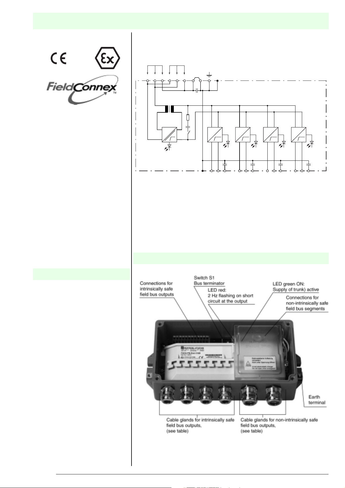
Connections for the non-intrinsically safe
fieldbus segment
Main cable
Trunk IN Trunk OUT
1B2B
5S3+4-
S1: Fieldbus termination, switchable
6S8+7-
S1
U
green
Output 1 Output 2 Output 3 Output 4
Composition
F2D0-FB-Ex4.*
FieldBarrier for IEC 61158-2 fieldbusses
U, I
11-10+
12S
U, I
red red red red
1234
15S14-13+
U, I
18S17-16+
Connections for the
intrinsically safe
fieldbus segments
U, I
21S20-19+
Function
The FieldBarrier connects a non-intrinsically safe fieldbus main line to 4 intrinsically safe output lines. Due to the
'increased safety' Ex e power feed concept, sufficient power is available to
feed a multitude of field devices. Each
output provides 40 mA. Up to 120 m of
cable can be connected to an output
and operated without a termination
resistor. The FieldBarrier is connected
to a fieldbus according to IEC 61158-2
(MBP) on the trunk side by means of Ex
e connection terminals. The trunk can
be fed to another FieldBarrier of other
fieldbus stations by means of the trunkout terminals (cascading). Faults on the
output lines have no negative influence
on the trunk due to the individual shortcircuit monitoring of each output. In
terms of plant reliability it is recommendable to connect one field device to
each output only.
T16395_ENG.xml 2003-04-24
Subject to reasonable modifications due to technical advances. Copyright Pepperl+Fuchs, Printed in Germany
1
Pepperl+Fuchs Group • Tel.: Germany +49 621 776-0 • USA +1 330 4253555 • Singapore +65 67799091 • Internet http://www.pepperl-fuchs.com
Page 2

Technical Data
Fieldbus connection
Main cable (Trunk)
Connection Input (Trunk in): Terminals 3+, 4-, 5s
Rated voltage 16 ... 32 V DC
Rated current 25 mA ... 22 mA (without load)
Outputs
Connection Output 1: terminals 10+, 11-, 12S shield;
Rated voltage ≥ 10 V at 40 mA
Rated current ≤ 40 mA
Short-circuit current ≤ 50 mA
Terminating impedance 100 Ω switchable on
Electrical isolation
Main wire/outputs Isolation is not affected by interference according to EN 50020, voltage peak value 375 V
Standard conformity
Electromagnetic compatibility NAMUR NE 21
Protection degree IEC/EN 60529
Fieldbus standard IEC 61158-2
Climatic conditions DIN IEC 721
Directive conformity
Electromagnetic compatibility standards
Directive 89/336/EG EN 61326, EN 50081-2
Ambient conditions
Ambient temperature see table
Storage temperature -40 ... 85 °C (233 ... 358 K)
Mechanical specifications
Connection type terminals
Core cross-section
Housing 258 mm x 114 mm x 84 mm (without cable glands)
Protection degree IP67
Cable diameter see table
Mass 2500 g
Mounting Panel mounting
Data for application in conjunction with
hazardous areas
EC-Type Examination Certificate PTB 02 ATEX 2086
Group, category, type of protection,
Temperature classification
Main cable (Trunk)
Safety maximum voltageUm 253 V AC
Outputs
Voltage Uo 15,75 V
Current I
Power Po 975 mW
Directive conformity standards
Directive 94/9 EU EN 50014, EN 50019, EN 50020, EN 50028
248 mA
o
Output (Trunk out): Terminals 7+, 8-, 6s
121 mA ... 74mA (at 20mA load per input)
230 mA ... 125 mA (at 40 mA load per input)
255 mA ... 135 mA (short-circuit on all outputs)
Output 2: terminals 13+, 14-, 15S shield;
Output 3: terminals 16+, 17-, 18S shield;
Output 4: terminals 19+, 20-, 21S shield
up to 2.5 mm
¬ II 2 (1) G EEx me [ia] IIC T4
2
F2D0-FB-Ex4.*
Supplementary information
EC-Type Examination Certificate, Statement of Conformity, Declaration of Conformity and instructions have to be observed. This information
can be found under www.pepperl-fuchs.com
T16395_ENG.xml 2003-04-24
Subject to reasonable modifications due to technical advances. Copyright Pepperl+Fuchs, Printed in Germany
Pepperl+Fuchs Group • Tel.: Germany +49 621 776-0 • USA +1 330 4253555 • Singapore +65 67799091 • Internet http://www.pepperl-fuchs.com
2
Page 3

Dimensions
F2D0-FB-Ex4.*
258
228
84
9.5
240
(57)
114
X
SW 1 SW 2
for fixing
with screws M6
Installation note
see system description
Accessories
Cover form gasket F 2 04-AVP3E
Cable gland closing plug M20 Ex #118302 (for SW 1 and SW 2)
Versions of cable glands
Identification (*) Type of cable gland Dimension X
(mm)
SW 1
(mm)
CG Plastic 140 20 24
CGB Nickel plated brass 140 20 24
CGS Stainless steel 140 22 24
CGAB Nickel plated brass, for armoured cable 160 24 24
Example for designation F2D0-FB-Ex4.*:
FieldBarrier with 4 outputs, nickel plated brass gland = F2D0-FB-Ex4.CGB
Cable diameter depending on the cable gland
Identification (*) Output cable diameter (mm) Trunk cable diameter (mm)
CG 5 ... 10 7 ... 12
CGB 5 ... 10 7 ... 12
SW 2
(mm)
CGS 5 ... 10 7 ... 12
8.5 ... 16 external
CGAB
6 ... 12 internal
0 ... 1.25 armour
Subject to reasonable modifications due to technical advances. Copyright Pepperl+Fuchs, Printed in Germany
3
Pepperl+Fuchs Group • Tel.: Germany +49 621 776-0 • USA +1 330 4253555 • Singapore +65 67799091 • Internet http://www.pepperl-fuchs.com
8.5 ... 16 external
6 ... 12 internal
0 ... 1.25 armour
T16395_ENG.xml 2003-04-24
Page 4

Ambient temperature range depending on the cable gland
Identification (*) Temperature range °C
CG -30 ... 70
CGB -40 ... 70
CGS -40 ... 70
CGAB -40 ... 70
F2D0-FB-Ex4.*
T16395_ENG.xml 2003-04-24
Subject to reasonable modifications due to technical advances. Copyright Pepperl+Fuchs, Printed in Germany
Pepperl+Fuchs Group • Tel.: Germany +49 621 776-0 • USA +1 330 4253555 • Singapore +65 67799091 • Internet http://www.pepperl-fuchs.com
4
 Loading...