

Page 1
Operating Instruction
Module-33/Ex-33
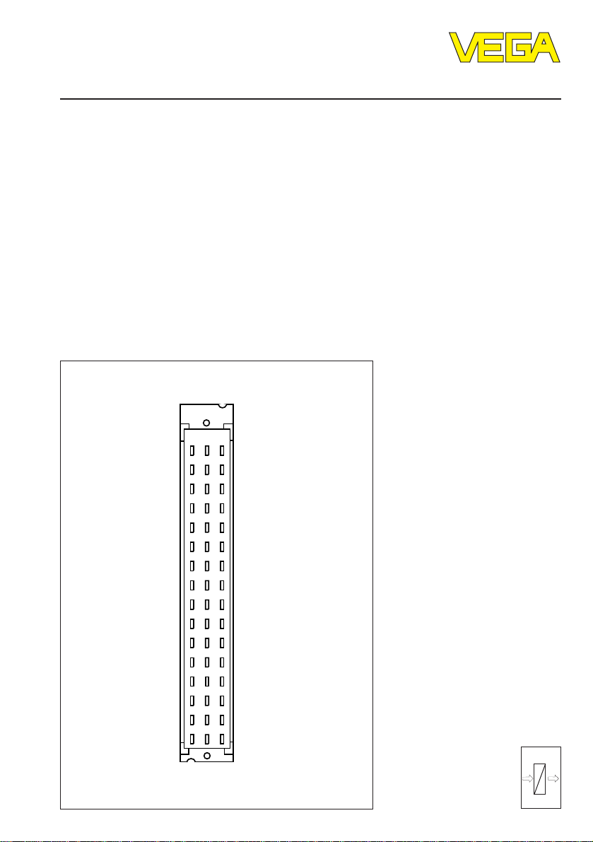
z b d
a c
o 1 o
o 3 o
o 5 o
o 7 o
o 9 o
o 11 o
o 13 o
o 15 o
o 17 o
o 19 o
o 21 o
o 23 o
o 25 o
o 27 o
o 29 o
o 31 o
Level and Pressure
out
in
Page 2
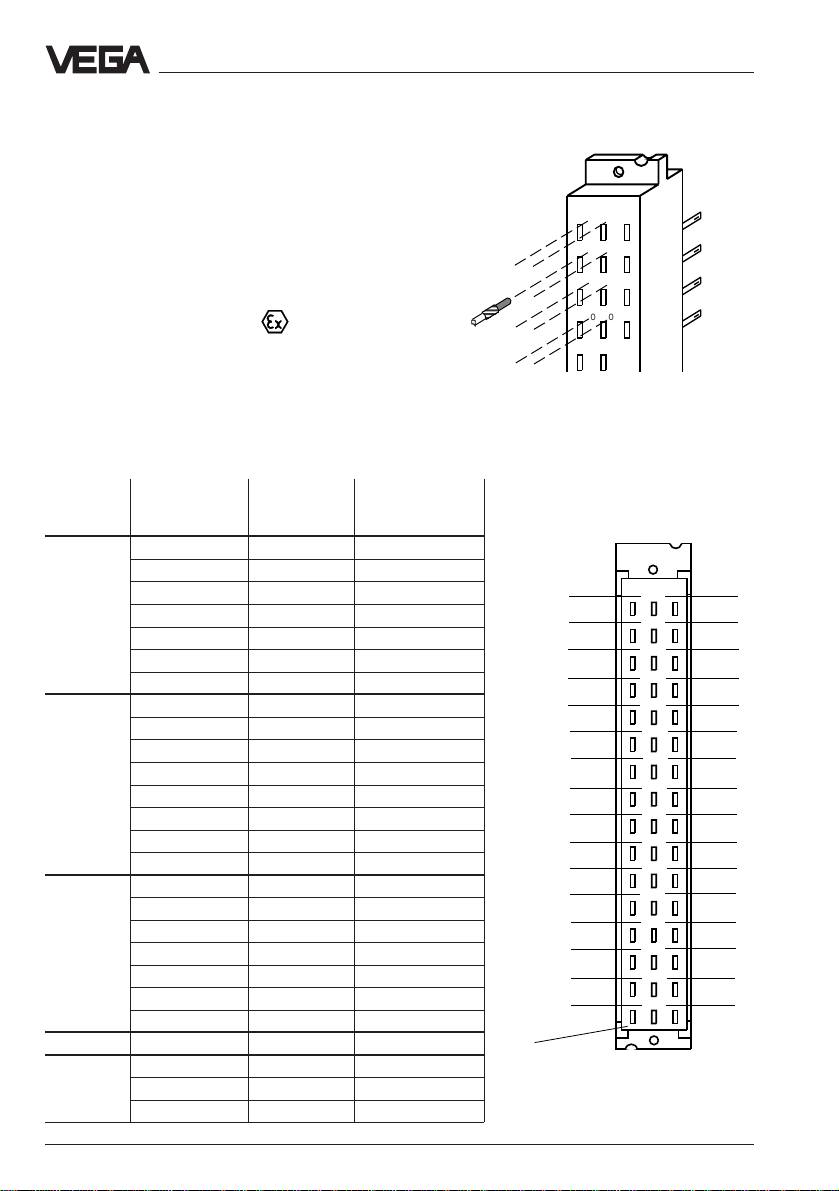
Coding of the module
z b d
o 31 o
o 29 o
o 27 o
o 25 o
o 23 o
o 21 o
o 19 o
o 15 o
o 11 o
o 7 o
o 3 o
o 1 o
o 5 o
o 9 o
o 13 o
o 17 o
a c
a1
a3
a5
a7
a9
a11
a13
a15
a17
a19
a21
a23
a25
a27
a29
a31
c1
c3
c5
c7
c9
c11
c13
c15
c17
c19
c21
c23
c25
c27
c29
c31
The multipoint connector can be provided with
coded pins to avoid interchanging of the different instruments in the carrier. Coded pins are
attached to each module. Equip the multipoint
connector with these coded pins acc. to the
table and figure on this page. The multiple
plug of VEGA-instruments has appropriate
holes (mechanical coding).
Module for Ex-instruments:
The multipoint connector must be provided
with three coded pins. The coded pin for the
Ex coding (position c23) avoids that not-Exinstruments are plugged into an Ex-module.
Instrument Instrument Instrument Ex-coding
group coding
LOG 571 CPU a1 / c3 -
EV a3 / c3 -
AA a5 / c3 -
AR a7 / c3 -
AT a9 / c3 -
MET 513 Ex a1 / c5 c23
TOR 521 Ex a9 / c7 c23
SEL 543-547 a1 / c9 -
Others TRENN 547 VEx a23 / c11 c23
EA a11 / c3 -
AD a13 / c3 -
TRENN 544 EX a1/c5 c23
TRENN 548 VEx a25 / c11 c23
514 EX a3 / c5 c23
515 Ex a5 / c5 c23
514 DEx a5/c5 c23
514 V a7/c5 -
515 V a7 / c5 -
514 VD a7/c5 -
522 Ex a11 / c7 c23
523 Ex a13 / c7 c23
527 Ex a15 / c7 c23
536 Ex a17 / c7 c23
537 Ex a19 / c7 c23
532 Ex a21 / c7 c23
COM 557 a27 / c11 -
Coded
pin
Product description
o o
o o
o o
o o
o o
Multipoint connector
(plug-in side)
2 Module-33/Ex-33
Page 3

Product description
Connection instructions for
Ex-applications
Mounting in carriers and housings
When a VEGA-instrument with Ex-approval is
mounted in a carrier or a single housing, a
module Ex-33 of VEGA must be used. Keep a
distance of at least 2 TE (10,16 mm) to module
cards of foreign manufacturers. The modules
or instruments must be generally installed
outside the hazardous area or further Exprotective measures must be taken.
Loop the lines of the intrinsically safe circuit
through the separating chamber and connect
to the appropriate position of the multipoint
connector.
Ex-separating chamber
An Ex-separating chamber (with modules for
the installation of VEGATRENN 547 VEx and
548 VEx) the wide separating chamber must
be used) must be mounted to the connections
of the Ex-module to guarantee sufficient air
and creeping distances. Proceed as follows:
Separating chamber
wide separating
chamber
When using a multipoint connector with screw
connection, the upper marked section on the
separating chamber of module Ex-33 E must
be broken off first.
Shift the separating chamber up to the
multipoint connector and fasten with the integral nut to the protruding fixing screw of the
multipoint connector.
Module-33/Ex-33 3
Page 4

VEGA Grieshaber KG
Am Hohenstein 113
D-77761 Schiltach
Phone (0 78 36) 50 - 0
Fax (0 78 36) 50 - 201
Fax (0 78 36) 50 - 203
ISO 9001
Technical data subject to alterations 2.21 645 / August ’97
 Loading...