

Page 1
Ope
p
rating Instructions
VEGADIF 55
4 … 20 mA/HART
Differe
ntial pressure
Page 2

Contents
Conten
1 About this document
2 For your safety
3 Product description
4 Mounting
ts
1.1 Function . . . . . . . . . . . . . . . . . . . . . . . . . . . . . . . . .
1.2 Target group . . . . . . . . . . . . . . . . . . . . . . . . . . . . . .
1.3 Symbolism used . . . . . . . . . . . . . . . . . . . . . . . . . . .
2.1 Authorised personnel . . . . . . . . . . . . . . . . . . . . . . . .
2.2 Appropriate use . . . . . . . . . . . . . . . . . . . . . . . . . . . .
2.3 Warning about misuse . . . . . . . . . . . . . . . . . . . . . . .
2.4 General safety instructions . . . . . . . . . . . . . . . . . . . .
2.5 Safety approval markings and safety tips . . . . . . . . .
2.6 Safety approval markings and safety tips . . . . . . . . .
2.7 CE conformity . . . . . . . . . . . . . . . . . . . . . . . . . . . . .
2.8 Safety instructions for Ex areas . . . . . . . . . . . . . . . .
2.9 Environmental instructions . . . . . . . . . . . . . . . . . . . .
3.1 Configuration . . . . . . . . . . . . . . . . . . . . . . . . . . . . . .
3.2 Principle of operation . . . . . . . . . . . . . . . . . . . . . . . .
3.3 Operation . . . . . . . . . . . . . . . . . . . . . . . . . . . . . . . .
3.4 Packaging, transport and storage . . . . . . . . . . . . . . .
4.1 General instructions . . . . . . . . . . . . . . . . . . . . . . . . .
4.2 Mounting instructions for flow measurement . . . . . . .
4.3 Mounting instructions for level measurement . . . . . . .
4.4 Mounting instructions with differential pressure
measurement . . . . . . . . . . . . . . . . . . . . . . . . . . . . .
4.5 Mounting for instruments with isolating diaphragms ..
4.6 Mounting instructions for seal with flange mounting . .
4.7 Heat insulation of instruments with flange isolating
diaphragm . . . . . . . . . . . . . . . . . . . . . . . . . . . . . . . .
4.8 Mounting instructions for wall or tube mounting . . . . .
4.9 Mounting control . . . . . . . . . . . . . . . . . . . . . . . . . . .
4
4
4
5
5
5
5
6
6
6
6
6
7
8
9
9
11
12
15
20
21
24
24
26
26
5 Connecting to power supply
5.1 Preparing the connection . . . . . . . . . . . . . . . . . . . . .
5.2 Connection procedure . . . . . . . . . . . . . . . . . . . . . . .
5.3 Wiring plan . . . . . . . . . . . . . . . . . . . . . . . . . . . . . . .
5.4 Take 4 … 20 mA test signal . . . . . . . . . . . . . . . . . . .
5.5 Load . . . . . . . . . . . . . . . . . . . . . . . . . . . . . . . . . . . .
5.6 Connection control . . . . . . . . . . . . . . . . . . . . . . . . .
5.7 Switch on phase . . . . . . . . . . . . . . . . . . . . . . . . . . .
6 Operation
6.1 Short description . . . . . . . . . . . . . . . . . . . . . . . . . . .
6.2 Local indication (optional) . . . . . . . . . . . . . . . . . . . .
6.3 Adjustment elements . . . . . . . . . . . . . . . . . . . . . . . .
6.4 Local adjustment - local indication not connected . . .
2 VEG
27
28
28
30
30
30
31
31731-EN-081119
32
32
35
37
ADIF 55 • 4 … 20 mA/HART
Page 3

Contents
6.5 Loca
6.6 Data memory module (optional) . . . . . . . . . . . . . . . .
6.7 Copy configuration data . . . . . . . . . . . . . . . . . . . . . .
6.8 Adjustment via HART handheld . . . . . . . . . . . . . . . .
6.9 Lock/Unlock adjustment . . . . . . . . . . . . . . . . . . . . . .
6.10 Default setting (reset) . . . . . . . . . . . . . . . . . . . . . . .
6.11 Menu schematic . . . . . . . . . . . . . . . . . . . . . . . . . . .
7 Set up
7.1 Warning instructions . . . . . . . . . . . . . . . . . . . . . . . .
7.2 Installation and function control . . . . . . . . . . . . . . . . .
7.3 Select language and measuring mode . . . . . . . . . . .
7.4 Position correction . . . . . . . . . . . . . . . . . . . . . . . . . .
7.5 Flow measurement . . . . . . . . . . . . . . . . . . . . . . . . .
7.6 Level measurement . . . . . . . . . . . . . . . . . . . . . . . . .
7.7 Differential pressure measurement . . . . . . . . . . . . . .
8 Maintenance and fault rectification
8.1 Maintenance . . . . . . . . . . . . . . . . . . . . . . . . . . . . . .
8.2 Remove interferences . . . . . . . . . . . . . . . . . . . . . . .
8.3 Replacement parts . . . . . . . . . . . . . . . . . . . . . . . . .
8.4 Instrument repair . . . . . . . . . . . . . . . . . . . . . . . . . . .
9 Dismounting
9.1 Dismounting steps . . . . . . . . . . . . . . . . . . . . . . . . . .
9.2 Disposal . . . . . . . . . . . . . . . . . . . . . . . . . . . . . . . . .
10 Supplement
10.1 Technical data and dimensions . . . . . . . . . . . . . . . .
l adjustment - local indication connected . . . . . .
40
44
45
48
48
49
52
57
57
57
58
59
64
74
78
78
78
79
80
80
81
31731-EN-081119
VEGADIF 55 • 4 … 20 mA/HA
Supplementary documentation
tion:
Informa
Supplementary documents appropriate to the ordered version come
with the delivery. You can find them listed in chapter "Product
description".
RT 3
Page 4
1 Abou
t this document
1 Abou
t this document
1.1 Function
This operating instructions manual provides all the information you
need for mounting, connection and setup as well as important
instructions for maintenance and fault rectification. Please read this
information before putting the instrument into operation and keep this
manual accessible in the immediate vicinity of the device.
1.2 Target group
This operating instructions manual is directed to trained personnel.
The contents of this manual should be made available to these
personnel and put into practice by them.
1.3 Symbolism used
Inform
ation, tip, note
This symbol indicates helpful additional information.
Cauti
on: If this warning is ignored, faults or malfunctions can
result.
Warning: If this warning is ignored, injury to persons and/or serious
damage to the instrument can result.
Danger: If this warning is ignored, serious injury to persons and/or
destruction of the instrument can result.
applications
Ex
This symbol indicates special instructions for Ex applications.
l List
The dot set in front indicates a list with no implied sequence.
à Action
Th
is arrow indicates a single action.
1 Sequence
Numbers set in front indicate successive steps in a procedure.
4 VEG
31731-EN-081119
ADIF 55 • 4 … 20 mA/HART
Page 5

your safety
2 For
or your safety
2 F
2.1 Authorised personnel
All operations described in this operating instructions manual must be
carried out only by trained specialist personnel authorised by the plant
operator.
During work on and with the device the required personal protection
equipment must always be worn.
2.2 Appropriate use
VEGADIF 55 is a differential pressure transmitter for measurement of
flow, level or differential pressure.
You can find detailed information on the application range in chapter
"Product description".
Operational reliability is ensured only if the instrument is properly used
according to the specifications in the operating instructions manual as
well as possible supplementary instructions.
For safety and warranty reasons, any invasive work on the device
beyond that described in the operating instructions manual may be
carried out only by personnel authorised by the manufacturer. Arbitrary
conversions or modifications are explicitly forbidden.
2.3 Warning about misuse
Inappropriate or incorrect use of the instrument can give rise to
application-specific hazards, e.g. vessel overfill or damage to system
components through incorrect mounting or adjustment.
31731-EN-081119
VEGADIF 55 • 4 … 20 mA/HA
2.4 General safety instructions
This is a high-tech instrument requiring the strict observance of
standard regulations and guidelines. The user must take note of the
safety instructions in this operating instructions manual, the countryspecific installation standards as well as all prevailing safety
regulations and accident prevention rules.
The instrument must only be operated in a technically flawless and
reliable condition. The operator is responsible for trouble-free
operation of the instrument.
During the entire duration of use, the user is obliged to determine the
compliance of the required occupational safety measures with the
current valid rules and regulations and also take note of new
regulations.
RT 5
Page 6

2 For
your safety
2.5 Safety
The safety approval markings and safety tips on the device must be
observed.
approval markings and safety tips
2.6 Safety approval markings and safety tips
The safety approval markings and safety tips on the device must be
observed.
2.7 CE conformity
VEGADIF 55 is CE conform to EMVG (89/336/EWG), NSR (73/23/
EWG) and corresponds to NAMUR recommendation EMC (NE 21).
Conformity has been judged according to the following standards:
l EMC: Emission EN 61326 instrument B, susceptibility EN 61326
supplement A (industrial area)
l LVD: EN 61010-1
The instrument corresponds to article 3 (3) of EG directive 97/23/EG
pressure device regulation and is designed according to good
engineering experience. VEGADIF 55 as basic instrument with PN 420
withtout isolating diaphragm is suitable for stable gases of group 1,
category 1.
2.8 Safety instructions for Ex areas
Please note the Ex-specific safety information for installation and
operation in Ex areas. These safety instructions are part of the
operating instructions manual and come with the Ex-approved
instruments.
2.9 Environmental instructions
Protection of the environment is one of our most important duties. That
is why we have introduced an environment management system with
the goal of continuously improving company environmental protection.
The environment management system is certified according to DIN
EN ISO 14001.
Please help us fulfil this obligation by observing the environmental
instructions in this manual:
l Chapter "Packaging, transport and storage"
l Chapter "Disposal"
6 VEG
31731-EN-081119
ADIF 55 • 4 … 20 mA/HART
Page 7
+ –
2
1
3
3 Produc
t description
Scope of delivery
Components
3 Produc
t description
3.1 Configuration
The scope of delivery encompasses:
l VEGADIF 55 differential pressure transmitter
l Version with lateral flanges of 316L or C22.8: in addition 2
ventilation valves, 316L
l Version with lateral flanges of 316L or C22.8 and lateral
ventilations: in addition 4 closing screws, 316L
l Optional accessory
l Documentation
- this operating instructions manual
- Short instruction (in housing cover)
- Final inspection protocol
- Supplementary instructions manual - 31732 "Service instruc-
tions for VEGADIF 55"
- Ex-specific "Safety instructions" (with Ex-versions)
- if necessary, further certificates
VEGADIF 55 consists of the following components:
l Process fitting w ith measuring cell
l Housing with electronics, optionally available with plug connector
l Housing cover, optionally available with local indication
The components are available in different versions.
Type label
31731-EN-081119
VEGADIF 55 • 4 … 20 mA/HA
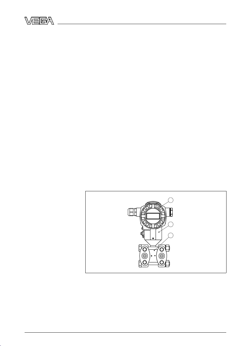
Fig. 1: VEGADIF 55 in
1 Housing cover, optionally available with subjacent on-site indication
2 Housing with electronics
3 Process fitting with measuring cell
The type label contains the most important data for identification and
use of the instrument:
l Article number
l Serial number
basic version
RT 7
Page 8
1
2
3
4
5
1
p
2
p
3 Produc
t description
hnical data
l Tec
l Article numbers documentation
With the serial number, you can access the delivery data of the
instrument via "
search". In addition to the type label outside, you can also find the
serial number on the inside of the instrument.
www.vega.com", "VEGA Tools" and "serial number
3.2 Principle of operation
Area of application
Functional principle
VEGADIF 55 is a differential pressure transmitter for measurement of
flow, level or differential pressure. Measured products are gases,
vapours and liquids.
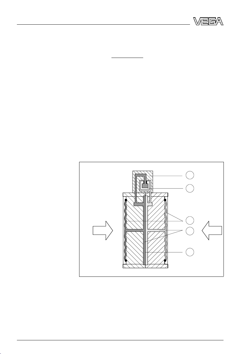
The sensor element is a metallic measuring cell. The process pressure
is transmitted via the separating diaphragm and filling oil to the
resistance measuring bridge (semi-conductor technology). The differential-pressure dependent change of the bridge voltage is measured,
further processed and converted into a corresponding output signal.
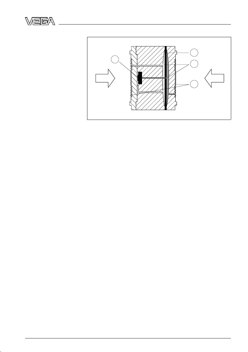
The configuration of the measuring cell differs depending on the
measuring range:
Fig. 2: Metal
1 Measuring element
2 Silicone diaphragm
3 Separating diaphragm
4 Filling oil
5 Integrated overvoltage arrester
measuring cell 10 mbar and 30 mbar
8 VEG
31731-EN-081119
ADIF 55 • 4 … 20 mA/HART
Page 9
1
2
3
4
1
p
2
p
3 Produc
t description
Voltage supply
Packaging
Fig. 3: Metal
1 Measuring element
2 Overload diaphragm/Middle diaphragm
3 Filling oil
4 Separating diaphragm
Two-wire electronics 4 … 20 mA/HART for power supply and
measured value transmission over the same cable.
The voltage supply range can differ depending on the instrument
version. The exact range is stated in chapter "Wiring plan " or
"Technical data" in the product information manual "VEGADIF 55".
measuring cell from 100 mbar
3.3 Operation
VEGADIF 55 can be adjusted with different adjustment media:
l via integrated adjustment keys and local indication (available as
options)
l an adjustment software according to FDT/DTM standard, e.g.
PACTware and PC
l with manufacturer-specific adjustment programs AMS™ or PDM
l With a HART handheld
The entered parameters are generally saved in VEGADIF 55,
optionally also in PACTware.
3.4 Packaging, transport and storage
Your instrument was protected by packaging during transport. Its
capacity to handle normal loads during transport is assured by a test
according to DIN EN 24180.
The packaging of standard instruments consists of environmentfriendly, recyclable cardboard. For special versions, PE foam or PE foil
is also used. Dispose of the packaging material via specialised
recycling companies.
31731-EN-081119
VEGADIF 55 • 4 … 20 mA/HA
RT 9
Page 10

3 Produc
t description
Transport
Transport inspection
Storage
Storage and transport
temperature
sport must be carried out under consideration of the notes on the
Tran
transport packaging. Nonobservance of these instructions can cause
damage to the device.
The delivery must be checked for completeness and possible transit
damage immediately at receipt. Ascertained transit damage or
concealed defects must be appropriately dealt with.
Up to the time of installation, the packages must be left closed and
stored according to the orientation and storage markings on the
outside.
Unless otherwise indicated, the packages must be stored only under
the following conditions:
l Not in the open
l Dry and dust free
l Not exposed to corrosive media
l Protected against solar radiation
l Avoiding mechanical shock and vibration
l Storage and transport temperature see chapter "Supplement -
Technical data - Ambient conditions"
l Relative humidity 20 … 85 %
10 VEG
31731-EN-081119
ADIF 55 • 4 … 20 mA/HART
Page 11

max. 380°
4 M
ounting
Materials, wetted parts
Mounting position
4 Moun
ting
4.1 General instructions
Make sure that the wetted parts of VEGADIF 55, especially the seal
and process fitting, are suitable for the existing process conditions
such as pressure, temperature etc. as well as the chemical properties
of the medium.
You find the specification in the "Product information manual"
VEGADIF 55 in chapter "Technical data".
Select such a mounting position that the instrument is in easy reach
when mounting or connecting as well as for later retrofitting of the
indicating and adjustment module. After loosening the pin, the housing
can be rotated by 380°.
Proceed as follows:
1 Loosen the pin with a 2 mm Allen wrench
2 Rotate the housing (max. up to 380°)
3 Tighten the pin
Installation position
Effective pressure lines
Valve block
31731-EN-081119
VEGADIF 55 • 4 … 20 mA/HA
Fig. 4: Direct
Due to the installation position of VEGADIF 55, a zero point shifting
can be caused, i.e. the measured values is not zero with empty vessel.
You can correct this zero point shoft either directly on the instrument
via the "E" key or the remote adjustment, see chapter "Operating
elements" and "Position adjustment".
You find general recommendations for wiring of effective pressure
lines in DIN 19210 "Effective pressure lines for flow systems" or the
corresponding national or international standards. When wiring
effective pressure lines outdoors, keep in mind to use a suitable
antifreeze, e.g. by using tube heat tracing. Wire effective pressure
lines with a monotonic decrease of at least 10 %.
Using a three-fold or five-fold valve block ensures easy setup,
mounting and maintenance without interrupting the process.
RT 11
the housing
Page 12
+
–
1
2
4
3
ounting
4 M
Oxygen applications
r:
Dange
Instruments for oxygen applications should be unpacked just before
mounting. After removing the protective cover of the process fitting, the
label "O₂" will be visible on the process fitting. Penetration of oil,
grease and dirt should be avoided. Danger of explosion!
Moisture
Flow measurement in
gases
Use the recommended cables (see chapter "Connecting to power
supply") and tighten the cable gland.
You can give your VEGADIF 55 additional protection against moisture
penetration by leading the connection cable downward in front of the
cable entry. Rain and condensation water can thus drain off. This
applies mainly to outdoor mounting as well as installation in areas
where high humidity is expected (e.g. through cleaning processes) or
on cooled or heated vessels.
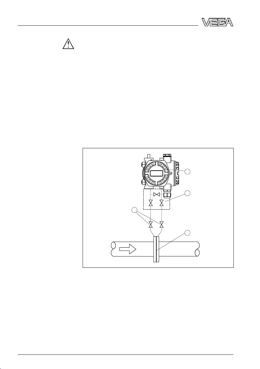
4.2 Mounting instructions for flow measurement
Fig. 5: Measurement
1 VEGADIF 55
2 Three-fold valve block
3 Block valves
4 Orifice or impact pressure probe
setup, flow measurement in gases with VEGADIF 55
à Mount VEGADIF 55 above the measurement loop so that
12 VEG
condensate can drain off in the process cable.
31731-EN-081119
ADIF 55 • 4 … 20 mA/HART
Page 13
+
–
1
2
3 3
5 5
6 6
7
4
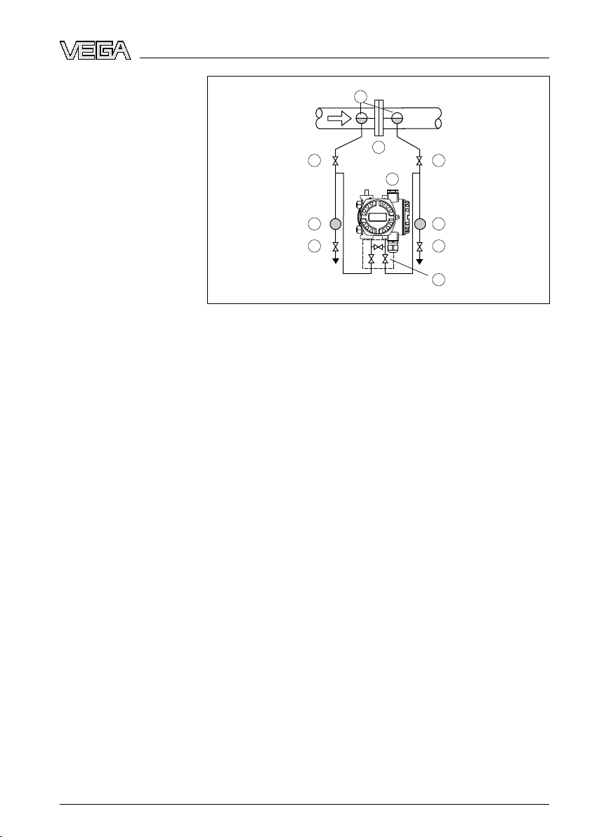
Flow measurement in
vapours
4 M
ounting
Fig. 6: Measurement
1 Condensate vessels
2 Orifice or impact pressure probe
3 Block valves
4 VEGADIF 55
5 Precipitator
6 Drain valves
7 Three-fold valve block
à Mount VEGADIF 55 below the measurement loop
à Mount condensate vessels at the same height with the discharge
socket and at the same distance to VEGADIF 55
à Fill the effective pressure lines to the height of the condensate
vessels before setup
setup, flow measurement in vapours with VEGADIF 55
31731-EN-081119
VEGADIF 55 • 4 … 20 mA/HA
RT 13
Page 14
+
–
1
2 2
3
5 5
6
4 4
ounting
4 M
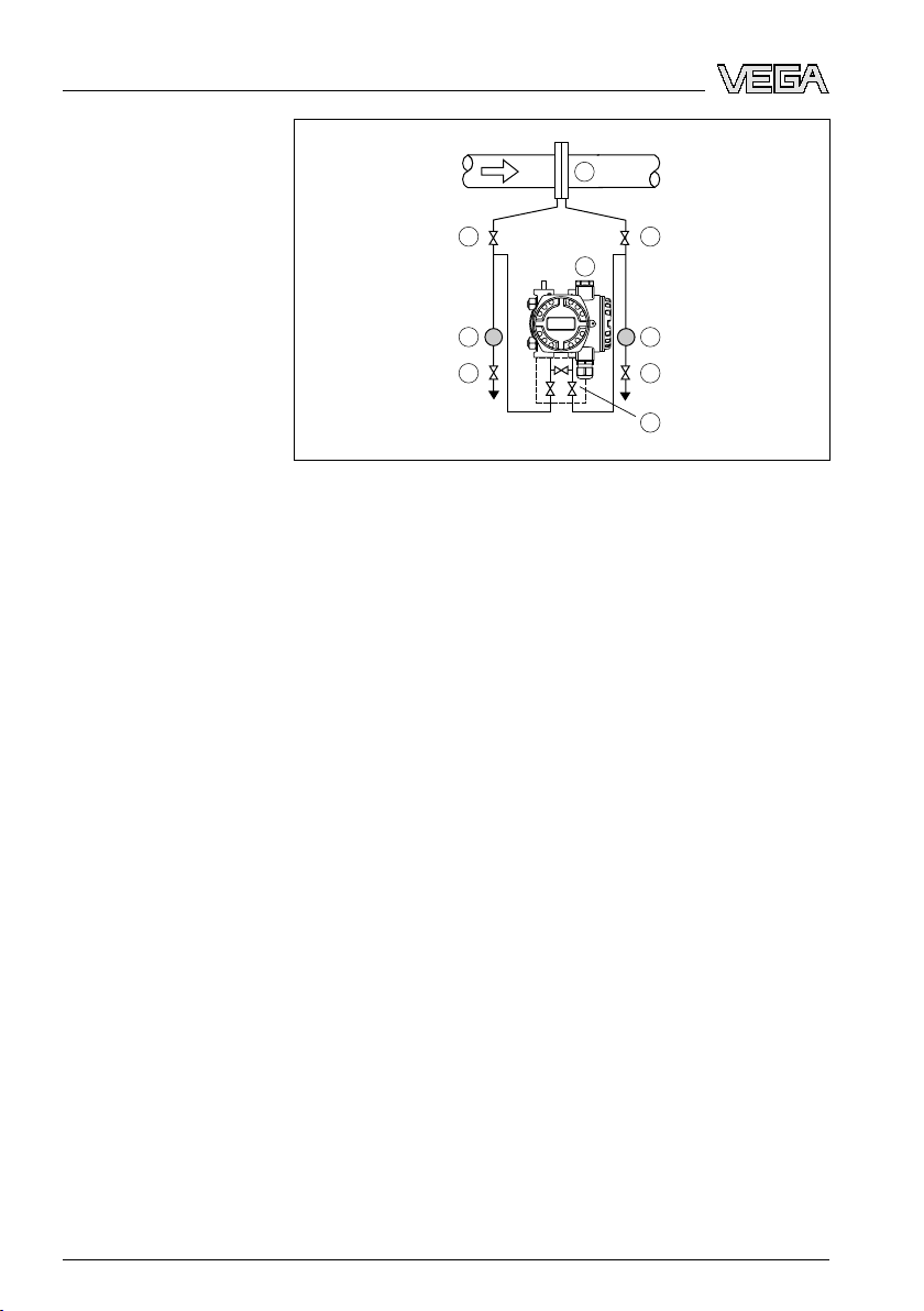
Flow measurement in
liquids
Fig. 7: Measurement
1 Orifice or impact pressure probe
2 Block valves
3 VEGADIF 55
4 Precipitator
5 Drain valves
6 Three-fold valve block
à Mount VEGADIF 55 below the measurement loop so that the
effective pressure lines are always filled with liquid and gas
bubbles can bubble up to the process line
à For measurements in products with solid content such as e.g. dirty
liquids, the installation of separators and drain valves is
recommended to enable collection and removal of debris and
sediment.
à Fill the effective pressure lines to the height of the condensate
vessels before setup
setup, flow measurement in liquids with VEGADIF 55
31731-EN-081119
14 VEG
ADIF 55 • 4 … 20 mA/HART
Page 15
+
p
atm
min.
p
atm
1
2
3
4
5
+
–
min.
p
atm
p
atm
1
2
4 M
ounting
Level measurement in
the open vessel with
effective pressure line
Level measurement in
the open vessel with
flange
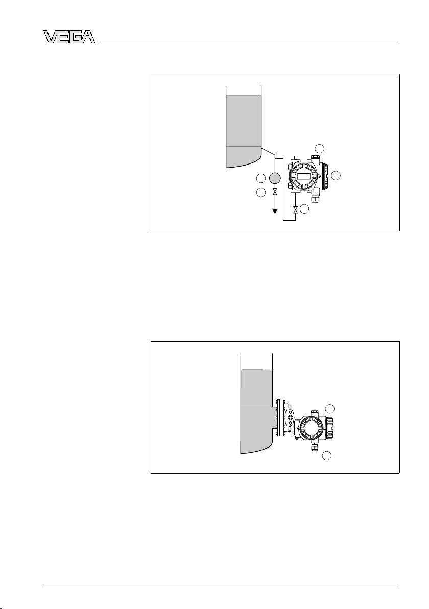
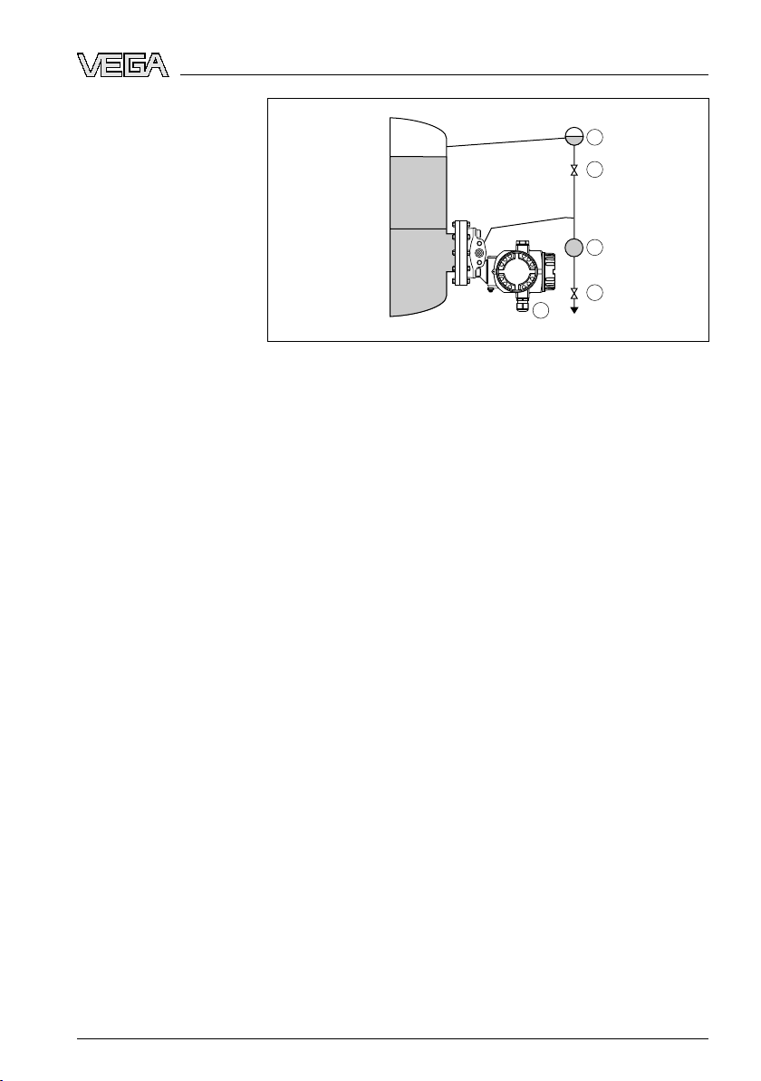
4.3 Mount
Fig. 8: Measurement
1 Minus side is open to the atmospheric pressure
2 VEGADIF 55
3 Block valve
4 Precipitator
5 Drain valve
à Mount VEGADIF 55 below the lower measurement connection so
that the effective pressure lines are always filled with liquid
à Minus side is open to the atmospheric pressure
ing instructions for level measurement
setup, level measurement in the open vessel
31731-EN-081119
VEGADIF 55 • 4 … 20 mA/HA
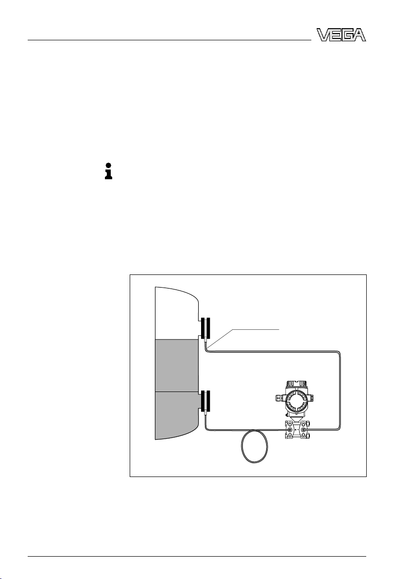
Fig. 9: Measurement
1 VEGADIF 55
2 Minus side is open to the atmospheric pressure
à Mount VEGADIF 55 directly to the vessel
à Minus side is open to the atmospheric pressure
setup, level measurement in the open vessel
RT 15
Page 16
+
–
min.
max.
1
3
4
3
4
5
1
2
ounting
4 M
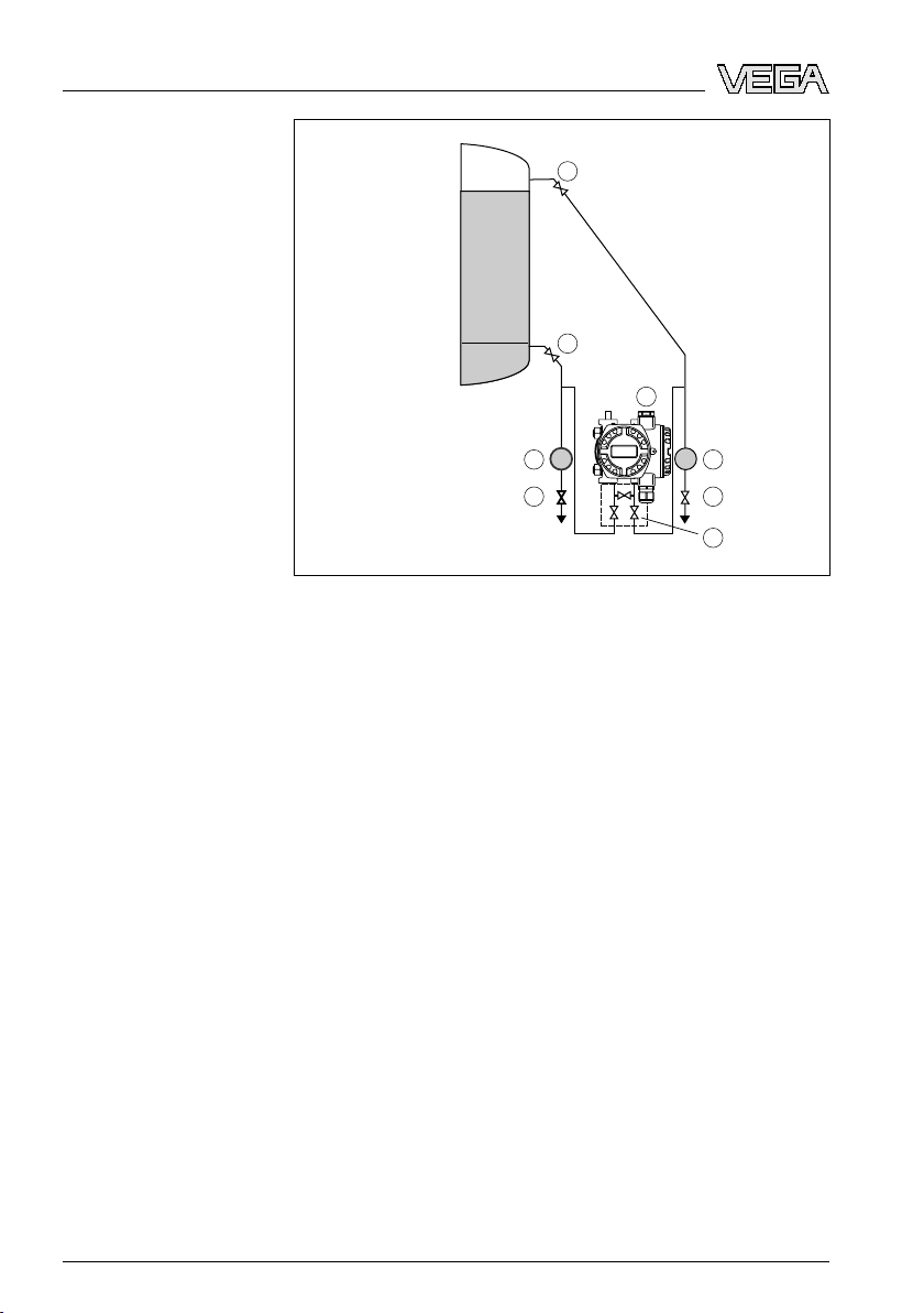
Level measurement in
closed vessel with effective pressure line
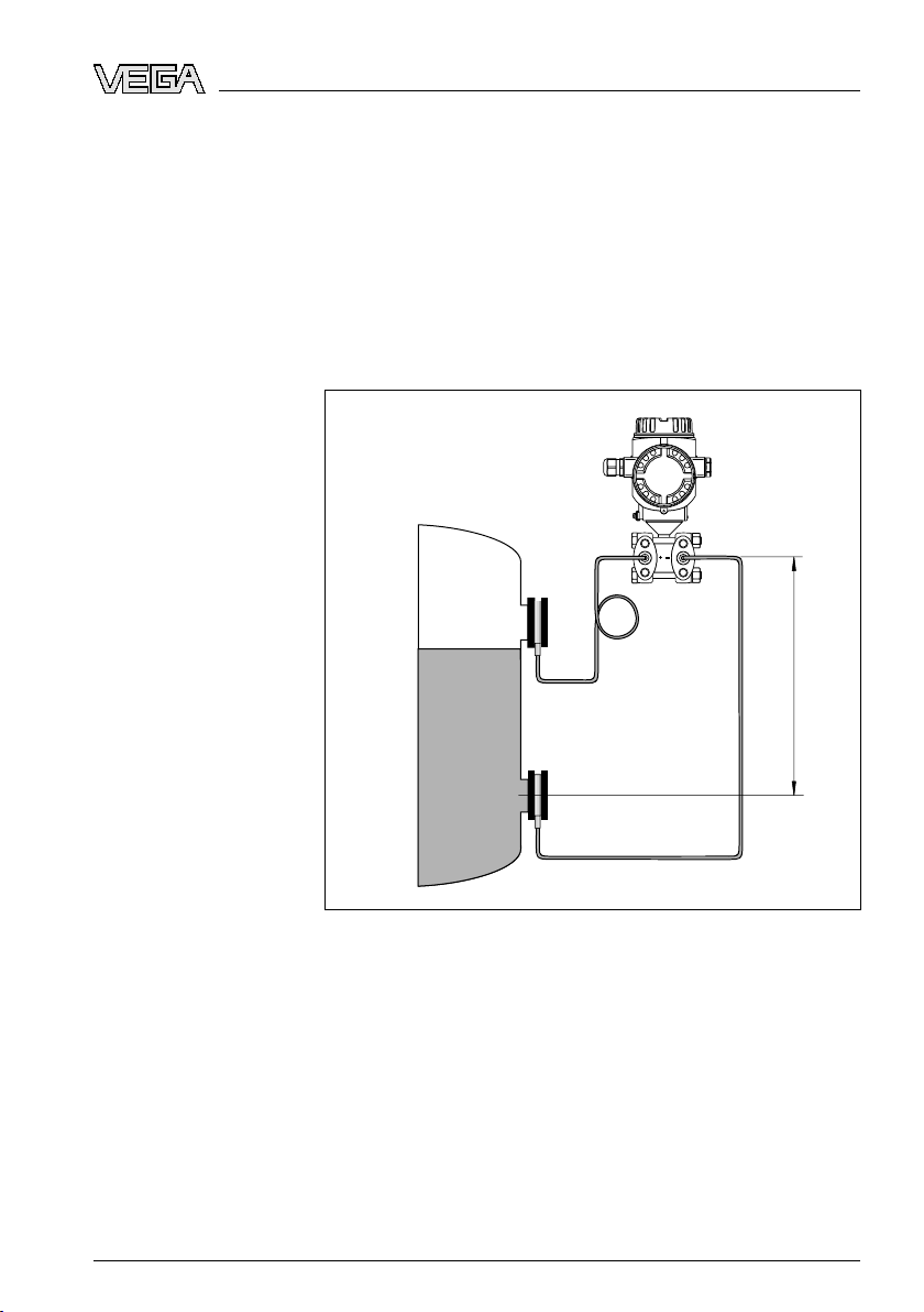
Fig. 10: Measurement
1 Block valves
2 VEGADIF 55
3 Precipitator
4 Drain valves
5 Three-fold valve block
à Mount VEGADIF 55 below the lower measurement connection so
that the effective pressure lines are always filled with liquid
à Connect minus side always above the max. level
à For measurements in products with solid content such as e.g. dirty
liquids, the installation of separators and drain valves is
recommended to enable collection and removal of debris and
sediment.
setup, level measurement in closed vessel
16 VEG
31731-EN-081119
ADIF 55 • 4 … 20 mA/HART
Page 17
+
–
max.
min.
1
2
3
4
+
–
min.
max.
1
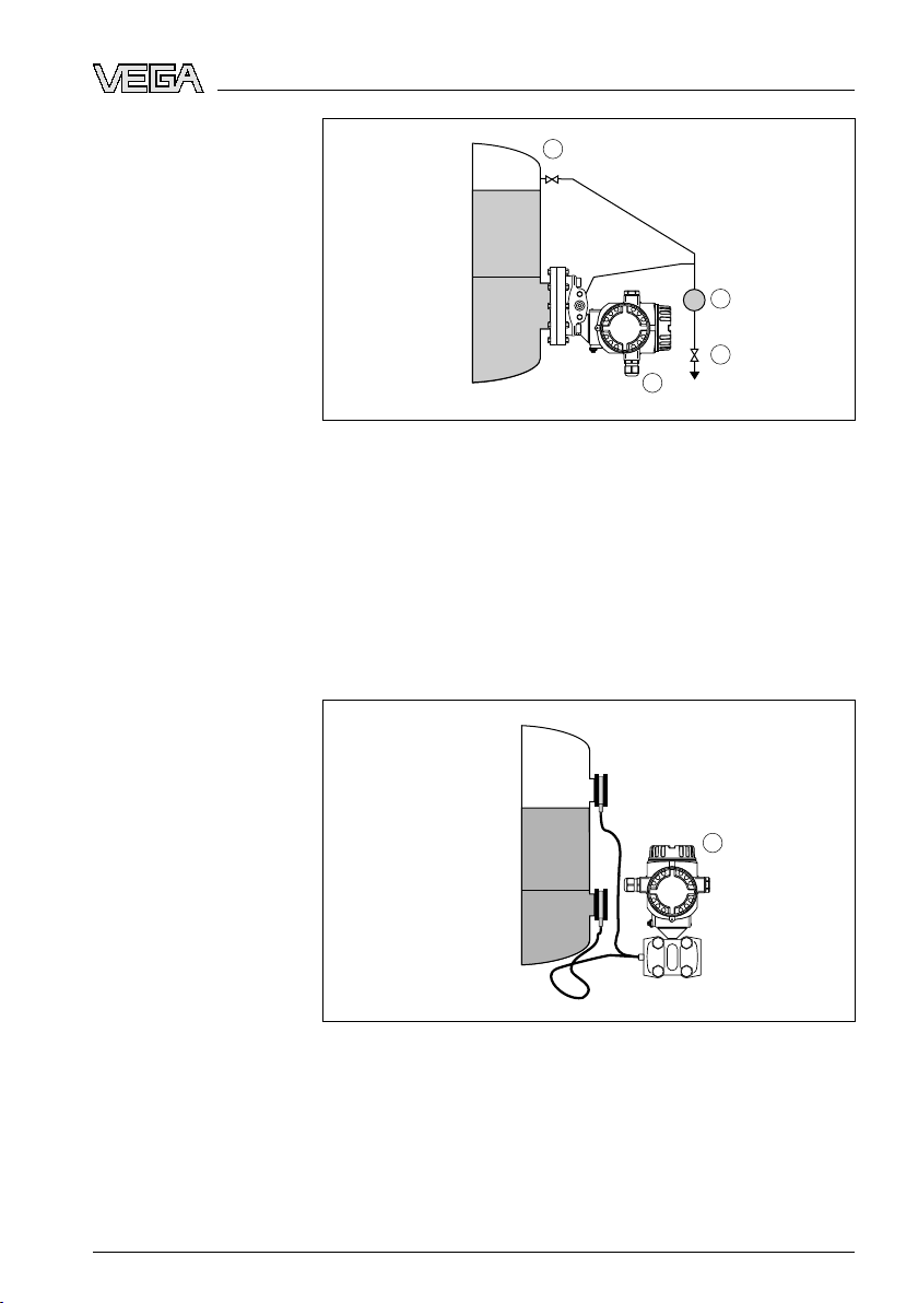
Level measurement in
closed vessel with
flange
4 M
ounting
Level measurement in
closed vessel with cell
isolating diaphragms
Fig. 11: Measurement
1 Block valve
2 Precipitator
3 Drain valve
4 VEGADIF 55
à Mount VEGADIF 55 directly to the vessel
à Connect minus side always above the max. level
à For measurements in products with solid content such as e.g. dirty
liquids, the installation of separators and drain valves is
recommended to enable collection and removal of debris and
sediment.
Fig. 12: Measurement
1 VEGADIF 55
à Mount VEGADIF 55 below the lower isolating diaphragm
à The ambient temperature should be the same for both capillaries
setup, level measurement in closed vessel
setup, level measurement in closed vessel
31731-EN-081119
VEGADIF 55 • 4 … 20 mA/HA
RT 17
Page 18
+
–
min.
max.
1
2
2
3
4
6
5 5
ounting
4 M
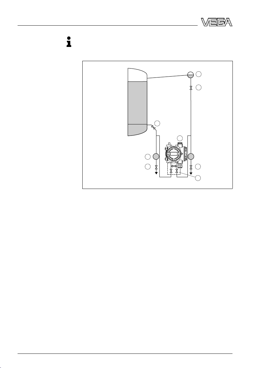
Level measurement in
closed vessel with
steam layer with effective pressure line
tion:
Informa
Level measurement is only ensured between the upper edge of the
lower and the lower edge of the upper pressure transmitter.
Fig. 13: Measurement
1 Condensate vessel
2 Block valves
3 VEGADIF 55
4 Precipitator
5 Drain valves
6 Three-fold valve block
à Mount VEGADIF 55 below the lower measurement connection so
that the effective pressure lines are always filled with liquid
à Connect minus side always above the max. level
à The condensate vessel ensures a constant pressure on the minus
side
à For measurements in products with solid content such as e.g. dirty
liquids, the installation of separators and drain valves is
recommended to enable collection and removal of debris and
sediment.
setup in closed vessel with superimposed steam
18 VEG
31731-EN-081119
ADIF 55 • 4 … 20 mA/HART
Page 19
+
–
min.
max.
1
2
3
4
5
Level measurement in
closed vessel with
superimposed steam
with flange
4 M
ounting
Fig. 14: Measurement
1 Condensate vessel
2 Block valve
3 Precipitator
4 Drain valve
5 VEGADIF 55
à Mount VEGADIF 55 directly to the vessel
à Connect minus side always above the max. level
à The condensate vessel ensures a constant pressure on the minus
side
à For measurements in products with solid content such as e.g. dirty
liquids, the installation of separators and drain valves is
recommended to enable collection and removal of debris and
sediment.
setup in closed vessel with superimposed steam
31731-EN-081119
VEGADIF 55 • 4 … 20 mA/HA
RT 19
Page 20

+
➃
1
2
33
+
–
1
2
4
5
6
4
5
2
3
4 M
ounting
Differential pressure
measurement in gases
and vapours
Differential pressure
measurement in liquids
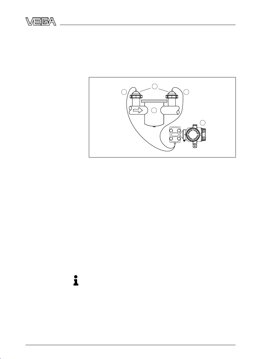
4.4 Mount
ing instructions with differential
pressure measurement
Fig. 15: Measurement
vapours with VEGADIF 55
1 VEGADIF 55
2 Three-fold valve block
3 Block valves
4 E.g. filter
à Mount VEGADIF 55 above the measurement loop so that
condensate can drain off in the process cable.
setup, differential pressure measurement in gases and
Fig. 16: Measurement
1 E.g. filter
2 Block valves
3 VEGADIF 55
4 Precipitator
5 Drain valves
6 Three-fold valve block
setup, flow measurement in liquids with VEGADIF 55
20 VEG
31731-EN-081119
ADIF 55 • 4 … 20 mA/HART
Page 21
+
–
1
4
22
3
4 M
ounting
Differential pressure
measurement in gases,
vapours and liquids
à Moun
à For measurements in products with solid content such as e.g. dirty
Fig. 17: Measurement
vapours and liquids with VEGADIF 55
1 Cell isolating diaphragm
2 Capillaries
3 E.g. filter
4 VEGADIF 55
à Mount isolating diaphragm with capillaries on top or laterally on the
à In vacuum applications: Mount VEGADIF 55 below the measure-
à The ambient temperature should be the same for both capillaries
t VEGADIF 55 below the measurement loop so that the
effective pressure lines are always filled with liquid and gas
bubbles can bubble up to the process line
liquids, the installation of separators and drain valves is
recommended to enable collection and removal of debris and
sediment.
setup, differential pressure measurement in gases,
pipeline
ment loop
31731-EN-081119
VEGADIF 55 • 4 … 20 mA/HA
4.5 Mounting for instruments with isolating
diaphragms
Isolating diaphragm
Note these general instructions to the isolating diaphragms:
Note:
isolating diaphragm together with a pressure transmitter forms
l An
a closed, calibrated system which is filled through openings in the
isolating diaphragm and the measuring element of the pressure
transmitter. These openings are sealed and must not be opened!
l Do not clean or touch the isolating diaphragm with hard or sharp
subjects
l Remove the diaphragm protection just before installation
l When using a mounting strap, there must be sufficient strain relief
for the capillaries to avoid bending them (bendingradius ≥ 100 mm)
RT 21
Page 22
+ –
+
–
≥ 100 mm
4 M
ounting
l Reme
mber that due to the hydrostatic pressure of the liquid
columns in the capillaries, a zero point shift can occur. The zero
point shift can be corrected, see also "Position adjustment".
l Keep the application limits of the isolating diaphragm filling oil in
mind according to the Product Information manual VEGADIF 55,
"Planning instructions isolating diaphragms"
Capillaries
To achieve more precise measuring results and avoid instrument
malfunctions, the capillaries must be mounted as follows:
Note:
l Vibr
ation-free (to avoid additional pressure fluctuations)
l Not close to heating or cooling lines
l Insulate them in cooler or warmer environment
l Lay wire with a bend radius ≥ 100 mm
l With isolating diaphragms on both sides, the ambient temperature
and length of both capillaries should be the same
l Always two identical isolating diaphragms (e.g. diameter, material
etc.) should be used for the minus and plus side (standard
shipment)
Fig. 18: Mounting VEGADIF 55 with
vacuum application: place the pressure transmitter below the lower isolating
diaphragm
22 VEG
isolating diaphragms and capillaries with
31731-EN-081119
ADIF 55 • 4 … 20 mA/HART
Page 23
+ –
+
–
H1
–
+
ounting
4 M
um application
Vacu
In applications under vacuum, we recommend mounting the pressure
transmitter below the lower isolating diaphragm. A vacuum load on the
isolating diaphragm due to the filling oil in the capillaries is thus
avoided.
When mounting the pressure transmitter above the lower isolating
diaphragm, the max. difference in height H1 must not be exceeded
according to the following illustrations. The max. difference in height
depends on the density of the filling oil and the smallest pressure
which can occur on the plus side of teh isolating diaphragm (empty
vessel), see following illustration.
31731-EN-081119
VEGADIF 55 • 4 … 20 mA/HA
Fig. 19: Mounting
above the lower isolating diaphragm
RT 23
Page 24
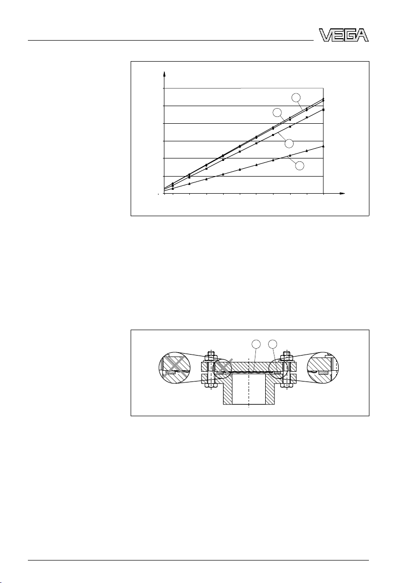
0,0
2,0
4,0
6,0
8,0
10,0
12,0
50
100 300 400 500 600 700 800 900 1000
mbar
m
200
2
1
3
4
1 2
4 M
ounting
Fig. 20: Diagram
vacuum applications depending on the pressure on the isolating diaphragm on
the plus side
1 Vegetable oil
2 Silicone oil
3 High temperature oil
4 Inert oil
max. mounting height above the lower isolating diaphragm in
4.6 Mounting instructions for seal with flange
mounting
Fig. 21: Mounting
1 Diaphragm
2 Seal
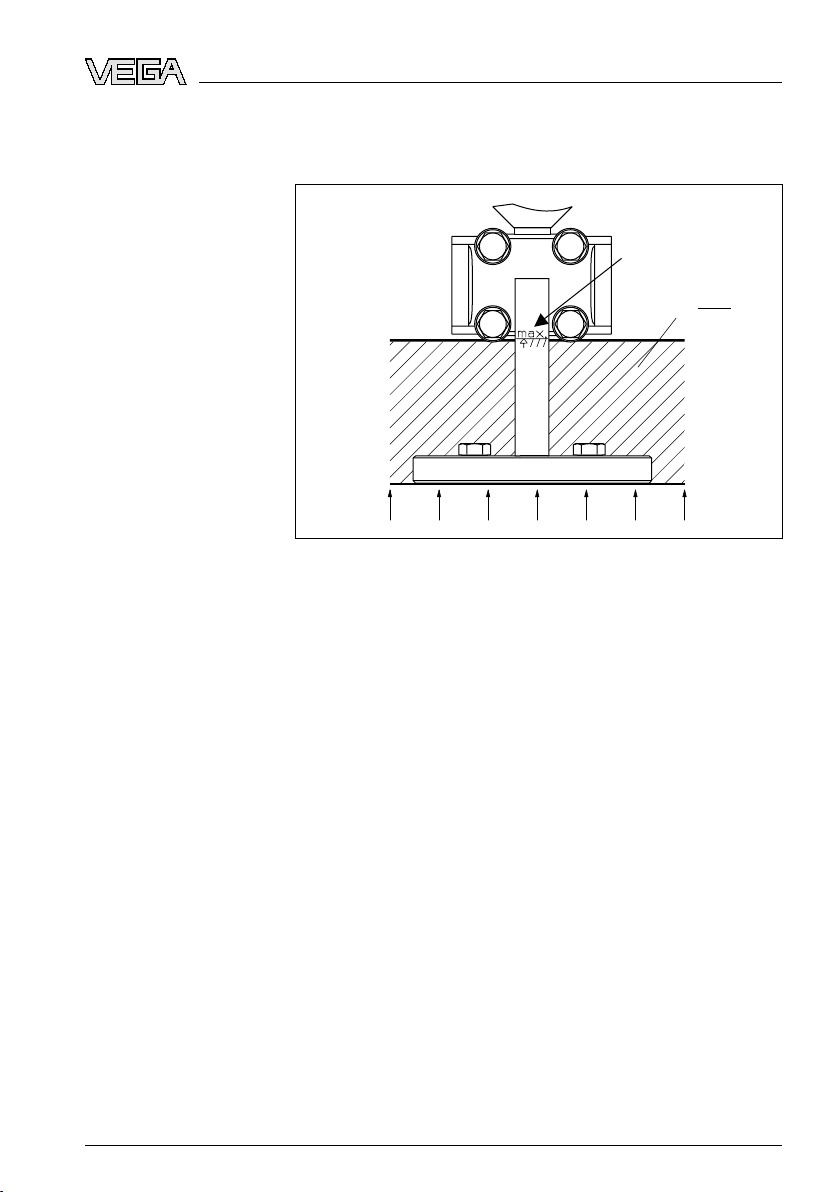
4.7 Heat insulation of instruments with flange
isolating diaphragm
VEGADIF 55 with unilateral flange isolating diaphragm must only be
isolated up to a certain height. The max. permissible isolating heigth is
marked on the instruments and applies to an isolating material with a
heat conductance ≤ 0.04 W/(m x K) and fa max. permitted ambient
24 VEG
the versions with flange or isolating diaphragm
31731-EN-081119
ADIF 55 • 4 … 20 mA/HART
Page 25
λ 0,04≤
W
m K•
T
A
T
P
4 M
ounting
temperature T
≤ 70 °C (158 °F) and process temperature TP< 350 °C
U
(662 °F). The data were determined under the critical application
"resting air".
Fig. 22: Max. permissible
isolating height
31731-EN-081119
VEGADIF 55 • 4 … 20 mA/HA
RT 25
Page 26
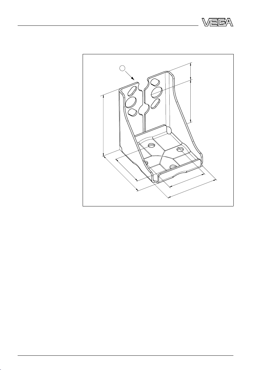
97,5
135
74
124
106
74
37,5
1
4 M
ounting
4.8 Mount
mounting
Fig. 23: Mounting
ing instructions for wall or tube
strap for wall or tube mounting
Take note of the following when mounting:
l Instruments with capillary lines: Mount capillaries with a bending
radius of ≥ 100 mm
l Slightly grease the mounting screws so that the threaded
connetion remains detachable
l For tube mounting, tighten the nuts on the strap with a torque of at
least 30 Nm
4.9 Mounting control
Check the following after mounting the instrument:
26 VEG
l Did you tighten all screws?
l Housing cover tightened?
l Did you tighten the closing screws and the ventilation valves?
31731-EN-081119
ADIF 55 • 4 … 20 mA/HART
Page 27

ecting to power supply
5 Conn
Note safety instructions
Take note of
safety instructions for Ex applications
Select power supply
Selecting connection
cable
5 Conn
ecting to power supply
5.1 Preparing the connection
Always keep in mind the following safety instructions:
l Connect only in the complete absence of line voltage
l If overvoltage surges are expected, overvoltage arresters should
be installed.
Ti
p:
We recommend using VEGA overvoltage arresters B63-48 and
ÜSB 62-36G.X.
In
hazardous areas you should take note of the appropriate
regulations, conformity and type approval certificates of the sensors
and power supply units.
Power supply and current signal are carried on the same two-wire
cable. The voltage supply range can differ depending on the
instrument version.
Data for power supply is specified in chapter "Technical data".
Provide a reliable separation between the supply circuit and the mains
circuits according to DIN VDE 0106 part 101. The VEGA power supply
units VEGATRENN 149AEx, VEGASTAB 690, VEGADIS 371 as well
as all VEGAMETs meet this requirement.
Bear in mind the following factors regarding supply voltage:
l Output voltage of the power supply unit can be lower under
nominal load (with a sensor current of 20.5 mA or 22 mA in case of
fault message)
The instrument is connected with standard, twisted and screened twowire cable with round cross section. An outer cable diameter of 5 ...
9 mm (0.2 ... 0.35 in) ensures the seal effect of the cable gland.
Cable screening and
grounding
Select connection cable for Ex
applications
31731-EN-081119
VEGADIF 55 • 4 … 20 mA/HA
Optimum shielding agains intefering influences can be achieved if the
screening is connected to both sides (in the switching cabinet and on
the instrument). If potential equalisation currents are expected, the
screening must be earthed only on one end, preferably on the
transmitter.
the corresponding regulations when used in hazardous areas. All
Note
Ex instruments are shipped with a separate Ex documentation with
additional technical data and instructions.
Provide potential equalisation inside and outside hazardous areas.
Connect all instruments to the local potential equalisation.
Instruments with integrated overvoltage protection must be grounded.
RT 27
Page 28

Test
Test
4... 20mA
5
4
3
2
1
ecting to power supply
5 Conn
Housing overview
5.2 Conne
ction procedure
Proceed as follows:
1 Unscrew the housing cover
2 Loosen compression nut of the cable entry
3 Remove approx. 10 cm (4 in) of the cable mantle, strip approx.
1 cm (0.4 in) insulation from the ends of the individual wires
4 Insert the cable through the cable gland into the sensor
5 Loosen the screws on the terminals
6 Insert the wire ends into the open terminals according to the wiring
plan
7 Tighten the screws of the terminals
8 Check the hold of the wires in the terminals by lightly pulling on
them
9 Connect the screen to the internal ground terminal, connect the
outer ground terminal with potential equalisation
10 Tighten the compression nut of the cable entry. The seal ring must
completely encircle the cable
11 Screw the housing cover on
The electrical connection is finished.
5.3 Wiring plan
Fig. 24: Housing
1 Housing
2 Bridge for 4 … 20 mA test signal
3 Internal ground terminal
4 External ground terminal
5 4 … 20 mA test signal between plus and test terminal
28 VEG
overview, view to the connection compartment
31731-EN-081119
ADIF 55 • 4 … 20 mA/HART
Page 29

Tes t4... 20mA
4...20 mA
10,5 V DC
11,5 V DC
Tes t
1
2
3
Han7D
–
+
+ –
VEGADIF55
–
+
1
5
4
6
7
8
2
3
VEGADIF55
M12x1
–
+
+–
–
+
Wiring plan
ecting to power supply
5 Conn
Wiring plan, plug connector Harting Han7D
Wiring plan, plug connector M12 x 1
Fig. 25: Wiring
1 Supply voltage/Signal output: min. supply voltage 10.5 V DC, bridge is
plugged according to illustration
2 Supply voltage/Signal output: min. supply voltage 11.5 V DC, position "Test"
is plugged with the bridge
Fig. 26: Wiring
electrical connection in the instrument; on the right, view to the plug on the
instrument
plan VEGADIF 55
plan VEGADIF 55 with plug connector Harting Han7D. On the left,
31731-EN-081119
VEGADIF 55 • 4 … 20 mA/HA
Fig. 27: Wiring
electrical connection in the instrument; on the right, view to the plug on the
instrument
plan VEGADIF 55 with plug connector M12 x 1. On the left,
RT 29
Page 30

Test
Test
1 2
≤
30
20
10,5
U
[V]
40 45
1282
1500
847
413
Test
3
4
Ω
R
Lmax
R
Lmax
U - 10,5 V
23 mA
[ ]
30
20
11,5
U
[V]
40 45
1239
1456
804
369
Test
3
4
≤
R
Lmax
U - 11,5 V
23 mA
Ω
R
Lmax
[ ]
ecting to power supply
5 Conn
5.4 Take 4 … 20 mA test
signal
Without interrupting the measurement you can tap a 4 … 20 mA test
signal via the plug and test terminal. By simply switching the bridges,
you can lower the min. supply voltage of the measuring instrument.
Through this it also possible to operate the instrument with a weaker
voltage source. To keep the measurement error below 0.1 %, the
current meter should show an inner resistance of < 0.7 Ω. Take note of
the bridge position according to the following illustrations.
Fig. 28: Left: Position
voltage 10.5 V DC. Right: Position of the bridge with test signal. Min. supply
voltage 11.5 V DC.
position of the bridge without test signal. Min. supply
5.5 Load
Fig. 29: Load
diagrams: Note position of the bridge and flame proofing. RLmax
max. load resistance, U voltage supply
1 Bridge for 4 … 20 mA test signal plugged in position "Non-test"
2 Bridge for 4 … 20 mA test signal plugged in position "Test"
3 Voltage supply 10.5 (11.5) … 30 V DC for EEx ia, 1/2 D, 1 GD, 1/2 GD, FM
IS and CSA IS
4 Supply voltage 10.5 (11.5) … 45 V DC for instruments for Ex-free area, 1/
3 D, EEx d, EEx nA, FM XP, FM DIP, FM NI, CSA XP and CSA Dust-Ex
30 VEG
5.6 Connection control
Check the following after electrical installation of the instrument:
l Does the supply voltage correspond to the specification on the
type label?
31731-EN-081119
ADIF 55 • 4 … 20 mA/HART
Page 31

ecting to power supply
5 Conn
the instrument connected according to chapter "Connecting to
l Is
power supply"?
l Did you tighten all screws?
l Did you screw up the housing covers?
The green LED on the electronics module lights for a few seconds or
the connected local indication lights if the voltage is switched on on the
instrument.
5.7 Switch on phase
Switch on phase
After VEGADIF 55 is connected to voltage supply or after voltage
recurrence, the instrument carries out a self-check. The following
steps are carried out:
l Internal check of the electronics
l For approx. 3 sec onds, the output signal takes on the value 12 mA
Then the actual measured value is displayed and the corresponding
current is transmitted to the cable.
1)
31731-EN-081119
VEGADIF 55 • 4 … 20 mA/HA
1)
The values correspond to the actual measured value as well as to the
settings already carried out, e.g. default setting.
RT 31
Page 32

6 Operati
on
Function/Configuration
6 Operati
on
6.1 Short description
The following adjustment media are available:
l Order code A - 4 … 20 mA/HART/outside/LCD: Adjustment via
local indication and 3 keys outside on the instrument
l Order code B - 4 … 20 mA/HART/inner/LCD: Adjustment via local
indication and 3 keys in the instrument
l Order code C - 4 … 20 mA/HART/inner/without: Adjustment with
local indication and 3 keys in the instrument
6.2 Local indication (optional)
As indication and adjustment, the 4-line liquid crystal indication (LCD)
is used. The local indication shows measured values, dialogue texts
as well as failure and information messages.
Functions:
32 VEG
31731-EN-081119
ADIF 55 • 4 … 20 mA/HART
Page 33

32 4 5
6
9
12
14
15
11
8
7
10
13
1
E
+
–
6 Operati
on
l 8-digit
measured value indication incl. signs and decimal point,
indication of the units, bar graph for current indication
l Easy and complete menu-guidance through arrangement of the
parameters into several levels and groups
l To enable easy navigation, each parameter is marked with a 3-
digit identification number
l Possibility to configure the indication according to the individual
requirements and requests, such as e.g. language, alternating
indication, contrast setting, indication of other measured values,
such as e.g. sensor temperature
l Comprehensive diagnostic functions (fault and warning message,
pointer etc.)
l Quick and reliable setup by means of quick setup menus
31731-EN-081119
VEGADIF 55 • 4 … 20 mA/HA
Fig. 30: Functions
1 Adjustment keys
2 Measured value indication mode
3 Function name
4 Value
5 Parameter identification number
6 Unit
7 Bar graph
8 Symbol
9 Header
10 Main line
11 Info line
12 Editing mode
13 Selection options
14 Editable value
15 Actual measured value
of the local indication
The following chart shows the possible symbols of the local indication.
Four symbols can appear at once.
RT 33
Page 34

6 Operati
on
Symbol Meaning
Alarm symbol
l Symbol flashes: Warning, instrument continues measuring
l Symbol flashes permanently: Error, instrument does not
continue measuring
Note: Where appropriate, the alarm symbol superimposes the
tendency symbol.
Lock
symbol
Adjustment of the instrument is locked
Note: Unlock instrument, see "Lock/Unlock adjustment".
Communication
Data transmission via communication
Root
symbol
Active mode "Flow measurement"
For the current output, the flow signal extracted by root is used
Tendency
The measured value increases
Tendency
The measured value falls
Tendency
Within the last minutes, the measured value was constant
symbol
symbol (rising)
symbol (falling)
symbol (steady)
34 VEG
31731-EN-081119
ADIF 55 • 4 … 20 mA/HART
Page 35

1
τ
1
4 5
HW-Version:
SW-Version:
250002271-–
HART
R
FIELDCO MMUNICATION PROTOCOL
1
2
21
PC
on
off
6
2
3
6 Operati
on
Position of the adjustment elements
6.3 Adj
ustment elements
The adjustment keys are either outside on the housing below the
protective cover or inside the electronics module. In addition there are
adjustment keys on the optional local indication.
Fig. 38: Adjustment
1 Adjustment keys
elements outside on the housing below the protective cover
31731-EN-081119
VEGADIF 55 • 4 … 20 mA/HA
Fig. 39: Adjustmetn
1 Adjustment keys
2 Module for optional indication
3 Module for optionally available memory module
4 DIP switch for locking/unlocking measured value-relevant parameters
5 DIP switch for damping on/off
6 Green LED for indication when the value is taken over
RT 35
keys inside
Page 36

6 Operati
Function of the
adjustment elements - local indication not
connected
Function of the operating elements - local indication connected
on
tion:
Informa
To carry out the respective function, the key or key combination must
be pushed for at least 3 seconds. For a reset, the key combination
must be pushed for at least 6 seconds.
l "-" key
- Accept me asurement begin, refer
l "+" key
ence pressure is on
- Accept measurement end, reference pressure is on
l "E" key
- Position adjustment
l "+
" key and "-" key and "E" key
- Reset of all parameters. The reset via the keys corresponds to
the software rest code 7864.
l "+" key and "E" key
- Copy
l "-" key and "E" key
configurati
device.
- Copy configurati
module.
l DIP switch 1
on data from optional data memory module to
on data from device to optional data memory
- To lock/unlock measured value-relevant parameters. Default
setting: off (unlocked)
l DIP switch 2
- Damping
l "+" key
- Navigation upward in the selection list
on/off, def
ault setting: on (damping on)
- Editing of the numerical values or signs within a function
l "-" key
- Naviga
tion downward in the selection list
- Editing of the numerical values or signs within a function
l "E" key
- Confirm entry
- Jump to the next menu item
l "+
" key and "E" key
- Contrast setting of the local display: highe
l "-" key and "E" key
- Contrast
setting of the local display: weak
r
er
31731-EN-081119
36 VEG
ADIF 55 • 4 … 20 mA/HART
Page 37

6 Operati
" key and "-" key
l "+
- Quit editing mode without saving the modified value
- In the menu you are within a function group: when pushing the
keys for the first time simultaneously, you jump one parameter
back within the function group. With every further simultaneous pushing you jump one level in the menu to the top
- You
l DIP switch 1
are in the menu on a selection level: With
simultaneous pushing you jump one level in the menu to the
top
every
- To lock/unlock measured value-relevant parameters. Default
setting: off (unlocked)
l DIP switch 2
- Damping on/off, def
6.4 Local adjustment - local indication not
connected
Informa
tion:
For adjustment of the instrument with a data memory module see
"Data memory module".
ault setting: on (damping on)
on
Measuring Mode - Pressure
31731-EN-081119
VEGADIF 55 • 4 … 20 mA/HA
If no local indication is connected, the following functions will be
possible via the three keys on the electronics module or outside on the
instrument:
l Position adjustment (zero point correction)
l Set measurement begin and measurement end
l Instrument reset, see chart in chapter "Operating elements"
tion:
Informa
The adjustment must be unlocked, see chapter "Lock/Unlock adjust-
ment".
By default, the instrument is set to mode Pressure. The mode can be
changed via the parameter "Measuring Mode", see chapter "Select
language and measuring mode".
The existing pressure must be within the nominal pressure limits of the
sensor, see specifications on the "Type label".
Carry out position adjustment:
1 Pressure on the instrument
2 Push "E" key at least for 3 s
3 Does the LED on the electronics module light briefly?
Yes: existing pressure was accepted as position adjustment
No: Existing pressure for position adjustment was not accepted,
note the adjustment limits
Set LRV:
RT 37
Page 38

6 Operati
on
Measuring Mode - Level
1 Pres
sure for LRV is on the instrument
2 Push "-" key at least for 3 s
3 Does the LED on the electronics module light briefly?
Yes: existing pressure was accepted as LRV
No: Existing pressure for LRV was not accepted, note the
adjustment limits
Set URV:
1 Pressure for URV is on the instrument
2 Push "+" key at least for 3 s
3 Does the LED on the electronics module light briefly?
Yes: existing pressure was accepted as URV
No: existing pressure for URV was not accepted, take note of the
adjustment limits
If no local indication is connected, the following functions will be
possible via the three keys on the electronics module or outside on the
instrument:
l Position adjustment (zero point correction)
l Set the lower and upper pressure value and assign a level value to
the lower or upper level value
l Instrument reset, see chart in chapter "Operating elements"
Informa
tion:
The adjustment must be unlocked, see chapter "Lock/Unlock adjust-
ment".
By default, the instrument is set to mode Pressure. The mode can be
changed via the parameter "Measuring Mode", see chapter "Select
language and measuring mode".
If "Level Mode" "Pressure Linearized" or "Height Linearized" or
"Calibration Mode" "dry" are selected, the "-" and "+" keys are without
function.
The existing pressure must be within the nominal pressure limits of the
sensor, see specifications on the "Type label".
See also "Quick setup menu" in chapter "Level measurement"
l Default settings of the parameters in mode "Level":
- LEVEL MODE = Linear
- CALIBRATION MODE = wet
- LIN. MEASURAND = %
- EMPTY CALIB. = 0 %
- FULL CALIB. = 100 %
Carry out position adjustment:
1 Pressure on the instrument
2 Push "E" key at least for 3 s
31731-EN-081119
38 VEG
ADIF 55 • 4 … 20 mA/HART
Page 39

6 Operati
on
Measuring Mode - Flow
3 Does
the LED on the electronics module light briefly?
Yes: existing pressure was accepted as position adjustment
No: Existing pressure for position adjustment was not accepted,
note the adjustment limits
Set lower pressure value:
1 Requested pressure for lower pressure value (EMPTY PRES-
SURE) is on the instrument
2 Push "-" key at least for 3 s
3 Does the LED on the electronics module light briefly?
Yes: Existing pressure was saved as lower pressure value
(EMPTY PRESSURE) and assigned to the lower level value
(EMPTY CALIB.)
No: Existing pressure was not saved as lower pressure value
(EMPTY PRESSURE). Take note of the adjustment limits
Set upper pressure value:
1 Requested pressure for upper pressure value (FULL PRESSURE)
is acting on the instrument
2 Push "+" key at least for 3 s
3 Does the LED on the electronics module light briefly?
Yes: Existing pressure was saved as upper pressure value (FULL
PRESSURE) and assigned to the upper level value (FULL CALIB.)
No: Existing pressure was not saved as upper pressure value
(FULL PRESSURE). Note the adjustment limits.
If no local indication is connected, the following functions will be
possible via the three keys on the electronics module or outside on the
instrument:
l Position adjustment (zero point correction)
l Set the max. pressure value and assign it to the max. flow value
l Instrument reset, see chart in chapter "Operating elements"
31731-EN-081119
VEGADIF 55 • 4 … 20 mA/HA
tion:
Informa
The adjustment must be unlocked, see chapter "Lock/Unlock adjust-
ment".
By default, the instrument is set to mode Pressure. The mode can be
changed via the parameter "Measuring Mode", see chapter "Select
language and measuring mode".
The "-" key is without function
The existing pressure must be within the nominal pressure limits of the
sensor, see specifications on the "Type label".
See also "Quick setup menu" in chapter "Flow measurement".
Carry out position adjustment:
1 Pressure on the instrument
RT 39
Page 40

6 Operati
on
h "E" key at least for 3 s
2 Pus
3 Does the LED on the electronics module light briefly?
Yes: existing pressure was accepted as position adjustment
No: Existing pressure for position adjustment was not accepted,
note the adjustment limits
Adjust max. pressure value:
1 Requested pressure for max. pressure value (MAX. PRESSURE
FLOW) is on the instrument
2 Push "+" key at least for 3 s
3 Does the LED on the electronics module light briefly?
Yes: Existing pressure was saved as max. pressure value (MAX.
PRESSURE FLOW) and assigned to the max. flow value (MAX.
FLOW).
No. Existing pressure for measurement begin was not saved as
max. pressure value. Note the adjustment limits
6.5 Local adjustment - local indication connected
If the local indication is connected, the three adjustment key are used
for navigation in the adjustment menu, see chapter "Function of the
operating elements".
Configuration of the
menu
40 VEG
The menu is divided into four levels. The three upper levels are used
for navigation whereas on the lowest level, numerical values are
entered, options selected and saved. The complete menu is shown in
chapter "Menu schematic". The "Adjustment menu" is composed
according to the selected mode, e.g. when the mode "Pressure" is
selected, only the functions necessary for this mode are displayed.
The parameters LANGUAGE and MODE are shown via the local
indication on the 1. selection level. Via the digital communication, the
parameter LANGUAGE is shown in group INDICATION and the
parameter MODE in the function group BASIC ADJUSTMENT.
31731-EN-081119
ADIF 55 • 4 … 20 mA/HART
Page 41

Measured value
GROUP SELCTION
DISPLAY
SETTINGS
EXTENDED SETUP
POS. ZERO ADJUST
POS INPUT VALUE
CALIB. OFFSET
POSITION ADJUSTMENT BASIC SETUP
OPERATING MENU
QUICK SETUP
MEASURING MODELANGUAGE
1
2
3
4
6 Operati
on
Fig. 40: Configuration
1 1. Selection level
2 2. Selection level
3 Function groups
4 Parameter
Selec
t option
of the menu
Example: Select the menu language "English"
German is selected as language. The active selection is marked by a
check mark in front of the me nu text.
t English with "+" or "-".
Selec
31731-EN-081119
VEGADIF 55 • 4 … 20 mA/HA
RT 41
Page 42

6 Operati
on
Edit
value
1. Confirm
check mark in front of the menu text (the language English is selected).
2. Move to the next menu item with "E".
Exa
chapter "Operating elements".
The local adjustment shows the parameter to be modified. The value
highlighted in black can be modified. The unit is determined "s" and
cannot be modified.
1. Push "+
highlighted in black.
selection with "E". The active selection is marked by a
mple: Set function "Damping value" from 2.0 s to 30.0 s. See also
" or "-" to reach the editing mode. 2. The first position is
the "+" key, you change number "2" to "3". 2. With the "E" key,
1. With
you confirm "3". Cursor jumps to t he next position (hihglighted in
black).
42 VEG
31731-EN-081119
ADIF 55 • 4 … 20 mA/HART
Page 43

6 Operati
e point is highlighted in black, i.e. you can now edit this position.
Th
on
1. Push "+
Cursor jumps to the next position. "↵" is displayed and is highlighted in
black, see next illustration.
With "E" you
illustration.
Th
with "E". You return to the editing mode with "+" or "-".
" or "-" until "0" is displayed. 2. Confirm "0" with the "E" key.
save the new value and quit the editing mode, see next
e new value for the damping is 30 s. You reach the next parameter
the pressure on the
Take
instrument over as value
31731-EN-081119
VEGADIF 55 • 4 … 20 mA/HA
mple: Adjust measurement end - assign 20 mA to the pressure
Exa
value 400 mbar.
The lower line on the local indication shows the existing pressure, here
400 mbar.
RT 43
Page 44

6 Operati
on
Move with "+" or "-" to the option "Confirm". Active selection is
highlighted in black.
Assi
gn value (400 mbar) to the parameter "GET URV" value
(400 mbar) with the key "E". The instrument confirms the adjustment
and jumps back to the parameter, here "GET URV" (see next
illustration).
Move to the next parameter with "E".
6.6 D
ata memory module (optional)
The data memory is a memory module that is plugged to the
electronics module and fulfils the following functions:
l Backup of the configuration data
l Copy the configuration data of a transmitter to another transmitter
l Cyclical recording of pressure and sensor temperature measured
values
l Recording of various events such as e.g. alarm messages,
configuration changes, counter for exceeding and decreasing of
the measuring range for pressure and temperature, exceeding and
decreasing of the user limits for pressure and temperature etc.
ning:
War
Warning! Remove or plug data memory only in idle condition from the
electronics module.
tion:
Informa
The data memory module can be retrofitted any time. After having
plugged to the electronics module and the instrument is powered
again, the data in the data memory module and in the instrument are
checked. The following messages can be displayed "W702, Histo-
ROM data not consistent" and "W706, Configuration in HistoROM and
device not identical". For measures see Additional instructions manual
"Service instructions VEGADIF 55", "Messages".
44 VEG
31731-EN-081119
ADIF 55 • 4 … 20 mA/HART
Page 45

Histo
ROM
2 1
PC
τ
Damping
[
] τ
2
1
on
off
off
on
Sensor
Display
6 Operati
on
Local indication not
connected
31731-EN-081119
VEGADIF 55 • 4 … 20 mA/HA
Fig. 54: Electronics
1 Optionally available data memory module
2 DIP switch
module with optionally available data memory module
6.7 Copy configuration data
Informa
tion:
To copy configuration data from the data memory module in an
instrument, the adjustment must be unlocked.
Copy configuration data from one instrument into a data memory
module:
tion:
Informa
The adjustment must be unlocked. See also chapter "Lock/Unlock
adjustment".
1 Separate instrument from voltage supply
2 Plug data memory module into the electronics module
3 Connect instrument again to voltage supply
4 Push "E" and "-" keys (at least 3 seconds) until the LED on the
electronics module lights
5 Wait approx. 20 seconds. Configuration data are loaded from the
instrument to the data memory module. The instrument does not
carry out a restart.
6 Separate instrument again from voltage supply
7 Remove memory module
8 Connect instrument again to voltage supply
RT 45
Page 46

6 Operati
Local adjustment
through local indication
(optional) or remote adjustment
on
configuration data from a data memory module to an
Copy
instrument:
Information:
The adjustment must be unlocked. See also chapter "Lock/Unlock
adjustment".
1 Separate instrument from voltage supply
2 Plug the data memory module into the electronics module.
Configuration data of a different instrument are saved in the data
memory module.
3 Connect instrument again to voltage supply
4 Push "E" and "+" keys (at least 3 seconds) until the LED on the
electronics module lights
5 Wait approx. 20 seconds. All parameters except DEVICE SERIAL
NO., DEVICE DESIGN., CUST. TAG NUMBER, LONG TAG
NUMBER, DESCRIPTION, BUS ADDRESS and the parameters of
the group POSITION ADJUSTMENT and PROCESS CONNECTION are loaded from the data memory module in the instrument.
The instrument carries out a restart.
6 Before you remove the data memory module from the electronics
module, you have to separate the instrument from the voltage
supply
Copy configuration data from one instrument into a data memory
module:
tion:
Informa
The adjustment must be unlocked. See also chapter "Lock/Unlock
adjustment".
1 Separate instrument from voltage supply
2 Plug data memory module into the electronics module
3 Connect instrument again to voltage supply
4 The selection for the parameter DOWNLOAD SELECT does not
influence an upload from the instrument in HistoROM (menu
path:"Group sel ection - Operating menu - Operating"
5 Select via the parameter HistoROM CONTROL the option
"Instrument - HistoROM" for the transmission direction (menu
path: "Group selection - Operating menu - Operating").
6 Wait approx. 20 seconds. Configuration data are loaded from the
instrument to the data memory module. The instrument does not
carry out a restart.
7 Separate instrument again from voltage supply
8 Remove memory module
9 Connect instrument again to voltage supply
Copy configuration data from a data memory module to an
instrument:
46 VEG
31731-EN-081119
ADIF 55 • 4 … 20 mA/HART
Page 47

6 Operati
tion:
Informa
The adjustment must be unlocked. See also chapter "Lock/Unlock
adjustment".
1 Separate instrument from voltage supply
2 Plug the data memory module into the electronics module.
Configuration data of a different instrument are saved in the data
memory module.
3 Connect instrument again to voltage supply
4 You select via the parameter DOWNLOAD SELECT which
parameter should be overwritten (menu path: "Group selection -
Operating menu - Operating")
Depending on the selection, the following parameters are overwritten:
Copy config.: All parameters except DEVICE SERIAL NO.,
DEVICE DESIGN., CUST. TAG NUMBER, LONG TAG NUMBER,
DESCRIPTION, BUS ADDRESS and the parameters of group
POSITION ADJUSTMENT and PROCESS CONNECTION.
Instrument change: All parameters except DEVICE SERIAL NO.,
DEVICE DESIGN. and the parameters of group POSITION
ADJUSTMENT and PROCESS CONNECTION
Electronics exchange: All parameters except the parameters of
group POSITION ADJUSTMENT. Factory setting: Copy config.
5 Select via the parameter HistoROM CONTROL the option
"HistoROM - Instrument" for the transmission direction (menu
path: "Group selection - Operating menu - Operating").
6 Wait approx. 20 sec. Configuration data are loaded from the data
memory module to the instrument. The instrument carries out a
restart.
7 Before you remove the data memory module from the electronics
module, you have to separate the instrument from the voltage
supply
on
31731-EN-081119
VEGADIF 55 • 4 … 20 mA/HA
RT 47
Page 48

EX EX
4…20 mA
min. 250 Ω
1
# % &
Copy
G H I
P Q R S
, ( )‘
A B C
Paste
Page
On
Page
Up
De
leteBksp
Insert
J K L
T UV
_ < >
D E
F
Hot Key
+ Hot Key
M N O
W XY Z
+ * /
4
7
.
2
5
8
0
375
FIELD COMMUNICATOR
3
6
9
-
9
6
DELTABAR:* * * * * * * *
ONLINE
1 QUICK SETUP
2 OPE
RATING MENU
4 SV 0 °C
3 PV 352 mbar
HELP SAVE
dsdmdm
df das.
asdas fa
asas la.
1
# % &
Copy
G H I
P Q R S
, ( )‘
A B C
Paste
Page
On
Page
Up
Del
eteBksp
Insert
J K L
T UV
_ < >
D E
F
Hot Key
+ Hot Key
M N O
W XY Z
+ * /
4
7
.
2
5
8
0
375
FIELD COMMUNICATOR
3
6
9
-
9
6
DELTABAR:* * * * * * * *
ONLINE
1 QUICK SETUP
2 OP
ERATING MENU
4 SV 0 °C
3 PV 352 mbar
HELP SAVE
dsdmdm
df das.
asdas fa
asas la.
4...20mA
Test
Test
3
2
1
6 Operati
on
6.8 Adj
ustment via HART handheld
You can adjust, check and use the additional functions of the
transmitter with a HART handheld along the 4 … 20 mA cable.
Fig. 55: Connection HART handheld, here
1 Required communication resistor ≥ 250 Ω
2 HART handheld
3 HART handheld connected directly to the instrument, also in Ex i area
With
protection EExd, do not connect the handheld in hazardous areas.
e.g. Field Communicator DXR375
Do not change battery of the handheld in hazardous areas. For
instruments with FM or CSA certificate, carry out the electrical
connection according to the installation attached in the certificate.
6.9 Lock/Unlock adjustment
After entering all parameters, you can protect your settings against
unauthorised access. You have the following possibilities to lock/
unlock the adjustment:
l via the DIP switch on the electronics module, on site on the
instrument
l via the local indication (optional)
l Via a HART handheld
The locking of the adjustment is marked on the local indication with the
key symbol. Parameters refering to the presentation such as e.g.
language and contrast indication can be still modified.
Note:
the adjustment is locked via the DIP switch, the locking can be ony
If
released via the DIP switch.
If the adjustment is locked via the local indication or remote
48 VEG
adjustment, the locking can be released either via the local indication
or the remote adjustment.
31731-EN-081119
ADIF 55 • 4 … 20 mA/HART
Page 49

Histo
ROM
2 1
PC
Damping
[
] τ
off
on
Sensor
Display
of f
on
2 1
off
on
2 1
Damping
[
]
τ
Damping
[
] τ
1 2 3
6 Operati
on
A modificati
on of the DIP switch "Damping on/off" does not influence
the damping time as long as the adjustment is locked. A modification is
only effective after the adjustment is unlocked again.
The chart gives an overview of the locking function:
Locking via Indication/Re-
ading of the
parameters
DIP switch Yes No No Yes No No
Local indica-
Yes No No No Yes No
tion
Remote adjust-
Yes No No No Yes No
ment
Modifying/Writing via local
indication
Modifying/Writing via remote adjustment
Unlocking via
DIP switch
Unlocking via
local indication
Unlocking via
remote adjustment
Lock/Unlock adjustment
on site via DIP switch
Fig. 56: Position DIP switch "Hardware
1 If necessary, dismount local indication (optional)
2 DIP switch 1 is set to "on": Adjustment is locked.
3 DIP switch 1 is set to "off": Adjustment is unlocked (adjustment possible)
locking" on the electronics module
Lock/Unlock adjustment
via local indication or
remote adjustment
31731-EN-081119
VEGADIF 55 • 4 … 20 mA/HA
The chart gives an overview of the locking/unlocking options:
Description
Lock adjustment Select parameter "Insert pin no.", menu path: "Operating
menu - Operating - Insert pin no.".
To lock the adjustment, you have to enter for the parameter a
number between 0 … 9999 and ≠100.
Unlock adjustment
Select parameter "Insert pin no.", menu path: "Operating
menu - Operating - Insert pin no.".
To unlock the adjustment, enter 100 for the parameter.
6.10 Default setting (reset)
By entering a certain code, you can reset the adjustments for the
parameters completely or only partially to default. You enter the code
via the parameter "ENTER RESET CODE" (menu path: " Group
selection - Operating menu - Operation"). There are different reset
codes for the instrument. The following chart shows the parameters
RT 49
Page 50

6 Operati
on
which can be reset by the respective reset code. T
the adjustment must be unlocked (see chapter "Lock/Unlock adjust-
ment").
Information:
Customer-specific parameter adjustments (default) remain even after
a reset. If you want that the parameters are reset to default, you have
to contact VEGA.
Reset code Description
1846 Indication Reset
l This reset resets all parameters relating to the display (DISPLAY Group)
l If a simulation is running, this will be terminated
l The instrument carries out a restart
62 PowerUp reset (warm start)
l This reset resets all parameters in the RAM. Data are reread from the EEPROM (processor is
re-initialised)
l If a simulation is running, this will be terminated
l The instrument carries out a restart
2710 Reset mode level
l Depending on the settings of the parameters LEVEL MODE and LIN MEASURAND, LINd
MEASURAND or COMB. MEASURAND all parameters necessary for this application are reset.
l If a simulation is running, this will be terminated
l The instrument carries out a restart
333 User reset
This reset resets the following parameters:
l Function group POSITION ADJUSTMENT
l Function group BASIC SETUP, except the customer-specific units
l Function group EXT. SETUP
l Function group: TOTALIZER SETUP
l Group OUTPUT
l Function group HART DATA: BUS ADDRESS and PREAMBLE NUMBER
l If a simulation is running, this will be terminated
l The instrument carries out a restart
o carry out a reset,
50 VEG
31731-EN-081119
ADIF 55 • 4 … 20 mA/HART
Page 51

code Description
Reset
7864 Total reset
8888 Data memory module reset
This reset resets the following parameters:
l Function group POSITION ADJUSTMENT
l Function group BASIC SETUP
l Function group EXT. SETUP
l Function group LINEARIZATION (an existing linearization chart may be deleted)
l Function group: TOTALIZER SETUP
l Group OUTPUT
l Function group HART DATA
l Function group MESSAGES
l All messages to be configured (type "Error") are set to "Warning", see also Supplementary
instruction manual "Service instructions VEGADIF 55", "Messages" and chapter "Fault
rectification"
l Function group USER LIMITS
l Function group SYSTEM 2
l If a simulation is running, this will be terminated
l The instrument carries out a restart
Measured value and event memory will be deleted. The data memory module must be plugged to
the electronics module during the reset.
Example LEVEL MODE = linear a nd LIN. MEASURAND = Height
l HEIGHT UNIT = m
l CALIBRATION MODE = wet
l EMPTY CALIB. = 0
l FULL CALIB. = Sensor final value converted in H²O, e.g. with a
500 mbar sensor: 5.99 mH²O
6 Operati
on
31731-EN-081119
VEGADIF 55 • 4 … 20 mA/HA
RT 51
Page 52

*
*
B B BB
A
B
A
*
1)
1)
1)
2)
*
X
*
*
2)
Continuation,
see the following page
Measured value
GROUP SELECTION
QUICK SETUP
LANGUAGE
Pressure
Level
Flo
w
POS. ZERO ADJUST
SET LRV
SET URV
MA
X.
FLOW
MAX PRESS. FLOW
EMPTY CALIB.
FULL CALIB.
POS. INPUT VALUE
CALIB. OFFSET
SET LRV
SET URV
GET LRV
DAMPING VALUE
DAMPING VALUE
GET URV
LEVEL MODE FLOW-MEAS. TYPE
CUSTOMER UNIT F
MAX. FLOW
CUST. UNIT FACT. F
MAX PRESS. FLOW
DAMPING VALUE
SETTINGS
OPERATING MENU
POSITION ADJUSTMENT BASIC SETUP
PRESS. ENG. UNIT
CUSTOMER UNIT P
CUST. UNIT FACT. P
Mass
p. cond.
MASS FLOW UNIT
Gas
norm cond.
Volume
p. cond.
NORM FLOW UNIT
Gas
std. cond.
STD. FLOW UNITUNIT FLOW
MEASURING MODE
MEASURING MODE
Pressure
Leve
l
Flow
MEASURING MO
DE
POS. ZERO ADJUST POS. ZERO ADJUST POS. ZERO ADJUST
DAMPING VALUE DAMPING VALUE
6 Operati
on
Fig. 57: Menu
1 Indication only via local indication
2 Indication only HART handheld
schematic part 1*: Group selection, basic setup, position adjustment, adjustment pressure and flow
6.11 Menu
* There are parameters which are only displayed if other parameters
are set respectively. For example, the parameter CUSTOMER UNIT P
is only displayed, if the option "CUSTOMER UNIT" was selected for
the parameter PRESS. ENG. UNIT. These parameters are marked
with a "*".
schematic
31731-EN-081119
52 VEG
ADIF 55 • 4 … 20 mA/HART
Page 53

F
F
F F F
E
E
E
D
D D D D
C
C
*
*
*
*
*
*
*
*
*
*
*
*
*
*
*
*
**
*
*
*
*
*
*
G
G
H
H
H
X
Continuation
BASIC SETUP “Level”;
see also the previous page
Level
LEVEL MODE
LIN. MEASURAND
CALIBRATION MODE
Linear
EMPTY CA
LIB.
EMPTY PRESSURE
FULL CALIB.
FULL PRESSURE
ADJUSTED DENSITY
wet
TANK VOLUME
TANK HEIGHT
HEIGHT UNIT
CUST. UNIT FACT. H
100% POINT
ZERO POSITION
ADJUST DENSITY
DENSITY UNIT
CUSTOMER UNIT H
dry
SET LRV
SET URV
DAMP
ING VALUE
Pressure
Linearize
d
LINd MEASURAND
HYDR. PRESS MIN.
HYDR. PRESS MAX.
DAMPING VALUE
Height
HEIGHT UN
IT
CUSTOMER UNIT H
CUST. UNIT FACT. H CUST. UNIT FACT. H CUST. UNIT FACT. H
Volume
UNIT VOLUME
CUSTOMER UNIT V
Mass
MASS UNIT
CUSTOMER UNIT M
%
MassVolume
%
UNIT V
OLUME
CUSTOMER UNIT V
CUST. UNIT FACT. V
MASS UNIT
CUSTOMER UNIT M
CUST. UNIT FACT. M
%Heigh
t+...Height+...
HEIGHT UNIT
CUSTOMER UNIT H
CUST. UNIT FACT. H
DENSITY UNIT
ADJUST DENSITY
HEIGHT UNIT
100% POINT
ZERO POSITION
CUSTOMER UNIT H
CUST. UNIT FACT. H
DAMPING VALUE
EMPTY CALIB.
FULL PRESSURE
EMPTY PRESSURE
FULL CALIB.
ADJUSTED DENSITY
Height
Lin
earized
COMB. MEASURAND
LEVEL MIN
LEVEL MAX
CALIBRATION MODE
wet
dry
6 Operati
on
31731-EN-081119
Fig. 58: Menu
VEGADIF 55 • 4 … 20 mA/HA
schematic part 2*: Selection level mode, calib. level
* There are parameters which are only displayed if other parameters
are set respectively. For example, the parameter CUSTOMER UNIT H
is only displayed, if the option "CUSTOMER UNIT" was selected for
the parameter HEIGHT UNIT. These parameters are marked with a
"*".
RT 53
Page 54

*
*
*
*
*
*
*
*
Editor TABLE
Measuring
Table
Display via
HART handheld terminal
only
Display via on-site
display only
EXTENDED SETUP
Pressure
TEMP. ENG UNIT TEMP. ENG
UNIT TEMP. ENG UNIT
Level
ADJUST DENSITIY
PROCESS DENSITY
SET LRV
SET URV
Flow
LOW FLOW CUT-OFF
SET L. FL. CUT-OFF
SET LRV
SET URV
EDITOR TABLE
TANK CONTENT MIN
TANK CONTENT MAX
TABLE SELECTION
LIN. EDIT MODE MEASURING TABLE
TANK DESCRIPTION
TOTALIZER SETUP
RESET TOTALIZER 1
TOTALIZER 2 UNIT
TOTALIZER 1 UNIT
FACT. U. U. TOTAL. 1
NEG. FLOW TOT. 1
TOT. 2 USER UNIT
FACT. U. U. TOTAL. 2
NEG. FLOW TOT. 2
TOT. 1 USER UNIT
LINEARISATION
Level
measuri
ng
mode only
Level measuring
mode only
Flow measuring
mode only
g
X-VAL.
Y-VA
L.
LINE-NUMB
ACTIVE LIN. TAB. X
ACTIVE LIN. TAB Y
TANK DESCRIPTION
TAB. ACTIVATE
LINEARISATION
TANK CONTENT MIN
TANK CONTENT MAX
TABLE SELECTION
EDITOR TABLE
6 Operati
on
Fig. 59: Menu
schematic part 3*: Extended adjustment pressure, level and flow, linearization, adjustment sum
counter
* There are parameters which are displayed only if other parameters
are correspondingly set. For example, the parameter TOTALIZER 1 is
only displayed, if the option "CUSTOMER UNIT" was selected for the
parameter TOTALIZER. These parameters are marked with a "*".
54 VEG
ADIF 55 • 4 … 20 mA/HART
31731-EN-081119
Page 55

2)
2)
2)
2)
2)
2)
2)
2)
2)
2)
2)
2)
2)
2)
2)
2)
2)
2)
2)
2)
2)
4)
4)
4)
4)
4)
3)
4)
OUTPUT
SET MAX. ALARM
SET MIN. CURRENT
OUTPUT CURRENT
OUTPUT FAIL MODE
ALT. CURR. OUTPUT
ASSIGN CURRENT
LINEAR/SQROOT
CURR. CHARACT.
TRANSMITTER INFO
HART DATA
MANUFACTOR ID
HART MESSAGE
BUS ADDRESS
DEVICE REVISION
PREAMBLE NUMBER
HART DATE
DEVICE TYPE
TRANSMITTER DATA
DEVICE SERIAL No
CUST. TAG NUMBER
ELECTR. SERIAL No
DEVICE DESIGN.
HARDWARE REF.
ADDITIONAL INFO.
SOFTWARE VERSION
CONFIG RECORDER
PCB TEMPERATURE
ALLOWED MIN. TEMP
ALLOWED MAX. TEMP
DIP STATUS
LONG TAG NUMBER
PROCESS CONNECTION
SEAL TYPE
Pmax PROC. CONN.
MAT. PROC. CONN. +
MAT. PROC. CONN. -
PROC. CONN. TYPE
SENSOR DATA
SENSOR MEAS. TYPE
Pmin SENS. DAMAGE
SENSOR SER. NO.
PRESS. SENS HILIM
MINIMUM SPAN
Pmax SENS. DAMAGE
MAT. MEMBRANE
PRESS. SENS LOLIM
FILLING FLUID
Tmin SENSOR
Tmax SENSOR
SENSOR H/WARE REV.
DISPLAYSAFETY CONFIRM.
ALTERNATE DATA
DISPLAY CONTRAST
MENU DESCRIPTOR
MAIN DATA FORMAT
SAFETY LOCK
SAFETY PASSWORD
CALIB. OFFSET
MEASURING MODE
CURRENT OUTPUT
DIGIT SETS
ACK. ALARM MODE
MAX. FLOW
MAX PRESS FLOW
LOW FLOW CUT-OFF
SET L. FLOW CUT-OFF
SET LRV
CONF. PASSWORD
SET URV
LINEAR/SQROOT
DAMPING VALUE
LANGUAGE]
DIAPHRAGM MAT. +
DIAPHRAGM MAT. -
NR OF REMOTE SEAL
FILL FLUID
MOUNTING THREAD
REMOTE SEAL +
REMOTE SEAL -
NUTS MATERIAL
DRAIN VENT MAT.
DRAIN VENT POS.
THREAD
BOLTS MATERIAL
4TH VALUE IS
4TH VALUE
SECONDARY VALUE
THIRD VALUE IS
THIRD VALUE
PRIMARY VALUE IS
PRIMARY VALUE
SECONDARY VAL. IS
DIGIT SETS
6 Operati
on
31731-EN-081119
Fig. 60: Menu
2 Indication only HART handheld
3 Only Measuring Mode - Level
4 Only Measuring Mode - Flow
schematic part 4*: Setting safety, indication and output, transmitter info
VEGADIF 55 • 4 … 20 mA/HA
RT 55
Page 56

*
*
I
J
*
*
I
J J J J J J J
Display via
HART handheld
terminal only
MEASURED VALUE
SIM. CURRENT
Alarm Warning
none LevelPressure Tan
k content
Flow
Current
SIM. LEVEL
SIM. PRESSURE SIM.
TANK CONT.SIM. FLOW VALUE SIM. ERROR NO.
PROCESS VALUE
PROCESS INFO
Pressure
Lev
el Flow
PEAK HOLD INDICATOR
COUNTER:T > Tmax
COUNTER: T< Tmin
MIN. M
EAS TEMP.
COUNTER:P > Pmax
MAX. MEAS. PRESS.
COUNTER:P < Pmin
MIN. MEAS. PRESS.
PCB COUNT: T > Tmax
PCB MAX. TEMP.
PCB COUNT: T>Tmin
PCB MIN. TEMP.
RESET PEAKHOLD
OPERATION
ENTER RESET CODE
OPERATING HOURS
INSERT PIN NO
DIAGNOSTICS
SIMULATION
SIMULATION MODE
MESSAGES
RESET ALL ALARMS
SELECT ALARM TYPE
ALARM DELAY
ALARM DISPL. TIME
ALARM STATUS
LAST DIAG. CODE
ACK. ALARM MODE
ACK. ALARM
Pmin ALARM WINDOW
Pmax ALARM WINDOW
Tmin ALARM WINDOW
Tmax ALARM WNDOW
USER LIMITS
SENSOR TEMP.
MEAS. VAL. TREND
PRESSURE
CORRECTED PRESS.
SENSOR PRESSURE
LEVEL BEFORE LIN
TANK CONTENT
MEAS. VAL. TREND MEAS. VAL. TREND MEAS. VAL. TREND
PRESSURE
CORRECTED PRESS.
SENSOR PRESSURE
SENSOR TEMP.
PRESSURE
CORRECTED PRESS.
SENSOR PRESSURE
SENSOR TEMP.
TOTALIZER 2
SUPPRESSED FLOW
TOTALIZER 1
TOTAL. 1 OVERFLOW
TOTAL. 2 OVERFLOW
AL. 2 OVERFLOW
HistoROM AVAIL.
HistoROM CONTROL
ERROR NO.
MEASURED VALUE MEASURED VALUE
6 Operati
on
Fig. 61: Menu
limits
schematic part 5*: Process info, peak hold indicator and operating data, simulation, messages, user
* There are parameters which are only displayed if other parameters
were adjusted respectively. These parameters are marked with a "*".
56 VEG
ADIF 55 • 4 … 20 mA/HART
31731-EN-081119
Page 57

7 Set
up
7 Set
up
7.1 Warning instructions
Warning:
If there is pressure acting on the instrument that is less than the
permissible min. pressure, the messages "E120 sensor low pressure"
and "E727 pressure transmitter overdriven" are outputted.
If there is pressure acting on the instrument that is higher than the
permissible max. pressure, the messages "E115 sensor gauge
pressure" and "E727 pressure transmitter overdriven" are outputted.
Messages E727, E115 and E120 are message types "Error" and can
be configured as "Warning" or "Alarm". As a default setting, these
messages are set to "Warning". This setting avoids that in applications
(e.g. cascade measurement) where overdriving of the sensor
measuring range is consciously accepted, the current output takes on
the set alarm current value.
In the following cases, we recommend setting the messages E727,
E115 and E120 to "Alarm":
For the application, it is not necessary to overdrive the sensor range.
A position adjustment should be carried out which must correct a large
deviation of the measuring range due to the installation position of the
instrument (e.g. instruments with isolating diaphragm).
7.2 Installation and function control
Before you set up the instrument, carry out the installation and
connection control according to checklist.
l Checklist see chapter "Installation control"
l Checklist see chapter "Connection control"
Local adjustment
31731-EN-081119
VEGADIF 55 • 4 … 20 mA/HA
7.3 Select language and measuring mode
The parameters LANGUAGE and MEASURING MODE are on the 1.
selection level, see also chapter "Local adjustment - Local indication
connected".
The following languages are available:
l Deutsch
l English
l Français
l Italiano
l Español
l Nederlands
l Chinese (CHS)
l Japanese (JPN)
RT 57
Page 58

up
7 Set
HART handheld
e following modes are available:
Th
l Pressure
l Level
l Flow
The parameter LANGUAGE is assigned in the HART handheld to the
group DISPLAY (OPERATING MENU: "DISPLAY"). You select the
menu language for the local indication via the parameter LANGUAGE.
The following languages are available:
l Deutsch
l English
l Français
l Italiano
l Español
l Nederlands
l Chinese (CHS)
l Japanese (JPN)
The parameter MODE is displayed in the HART handheld in the
QUICK SETUP menus and in the function group BASIC SETUP
(OPERATING MENU: "SETTINGS" - "BASIC SETUP").
The following modes are available:
l Pressure
l Level
l Flow
7.4 Position correction
Due to the installation position of the instrument, the measured value
can be shifted, i.e. the measured value does not show zero with empty
vessel. Three different possibilities for a position adjustment are
offered (menu path: ("GROUP SELECTION - OPERATING MENU -
SETTINGS - POSITION ADJUSTMENT").
Parameter
name
Position correction (685)
Entry
58 VEG
Description
Input position adjustment - the pressure difference betwen
zero (set value) and measured pressure must not be known
(there is a reference pressure on the instrument).
Example:
l MEASURED VALUE = 2.2 mbar
l You correct the MEASURED VALUE via the parameter
POS. ZERO ADJUST with the option "Confirm", i.e. you
assign the value 0 to the existing pressure
l MEASURED VALUE (after pos. zero adjust) = 0 mbar
l The current value is also corrected
l Default setting 0
31731-EN-081119
ADIF 55 • 4 … 20 mA/HART
Page 59

7 Set
up
Parameter
name
value (563)
Set
Entry
Position offset
(319)
Entry
Description
Input position adjustment - the pressure difference betwen
zero (set value) and measured pressure must not be known
(there is a reference pressure on the instrument).
Example:
l MEASURED VALUE = 0.5 mbar
l For the parameter POS. INPUT VALUE you enter the
requested set value for the MEASURED VALUE, e.g.
2 mbar (valid: MEASURED VALUEnew = POS. INPUT
VALUE)
l MEASURED VALUE (after pos. zero adjust) = 2 mbar
l The parameter CALIB. OFFSET shows the resulting
pressure difference (offset) by which the MEASURED
VALUE was corrected. This applies: CALIB. OFFSET =
MEASURED VALUEold - POSITION POS. INPUT
VALUE, here: CALIB. OFFSET = 0.5 mbar -2 mbar =
-1.5 mbar)
l The current value is also corrected
l Default setting 0
Input position adjustment - the pressure difference between
zero (set value) and measured pressure is known (there is a
reference pressure on the instrument).
Example:
l MEASURED VALUE = 2.2 mbar
l Via the parameter CALIB. OFFSET you enter the value by
which the MEASURED VALUE should be corrected. To
correct the MEASURED VALUE to 0 mbar, you have to
enter the value 2.2 (valid: MEASURED VALUEnew =
MEASURED VALUEold - CALIB. OFFSET)
l MEASURED VALUE (after adjustment for calib. offset) =
0 mbar
l The current value is also corrected
Factory setting
l 0
Preparations
31731-EN-081119
VEGADIF 55 • 4 … 20 mA/HA
7.5 Flow measurement
Note:
ally, VEGADIF 55 is used in the basic version for flow
Norm
measurements.
Before adjusting VEGADIF 55, you have to clean the effective
pressure lines and the instrument must be filled with the medium.
RT 59
Page 60

+
–
I
II
+
6
7
3
24
AB
A
B
+
1
5
6
7
+
–
24
3
II
I
IIIIII
7 Set
up
Fig. 62: Preferred
I VEGADIF 55
II Three-fold valve block
2.4 Inlet valves
3 Breather valve
6.7 Vent valves on VEGADIF 55
A, B Block valves
60 VEG
Fig. 63: Preferred
I VEGADIF 55
II Three-fold valve block
III Precipitator
1.5 Drain valves
2.4 Inlet valves
3 Breather valve
6.7 Vent valves on VEGADIF 55
A, B Block valves
installation for gases
installation for liquids
31731-EN-081119
ADIF 55 • 4 … 20 mA/HART
Page 61

up
7 Set
d as follows to prepare for the actual adjustment:
Procee
1 Close valve 3
2 Fill measuring system with medium
Open valves A, B, 2, 4: Medium flows in
3 If necessary, clean the differential pressure lines: - with gases by
blowing out with compressed air - with liquids by rinsing.
2)
For this purpose close valve 2 and 4, i.e. block the instrument.
Then open valve 1 and 5 so that the effective pressure lines blow
out/rinse.
After cleaning, close valves 1 and 5
3)
4)
4 Vent instrument
Open valves 2 and 4: Medium flows in
Close valve 4: Minus side will be closed
Open valve 3: Equalisation plus and minus side
Briefly open valve 6 and 7, then close again: Fill the measuring
instrument completely with the medium and remove air
5 Carry out position adjustment if the following conditions apply. If
the conditions are not fulfilled, then carry out the position
adjustment only after step 6. See "Quick Setup menu" in chapter
"Flow measurement" and chapter "Position adjustment". Conditions:
- The process cannot be blocked.
- The pressure extraction positions (A and B) are at the same
geodesic height.
6 Set measurement loop to operation
Therefore close valve 3: Separate plus and minus side
Open valve 4: Connect minus side
Now:
Valves 1, 3, 5, 6 and 7 are closed
5)
Valves 2 and 4 open
Valves A and B open (if available)
7 Carry out position adjustment if the flow must be blocked. In this
case, step 5 is deleted. See "Quick Setup menu" in chapter "Flow
measurement" and chapter "Position adjustment".
8 Carry out adjustment, see "Informationen on flow measurement" in
chapter "Flow measurement"
31731-EN-081119
VEGADIF 55 • 4 … 20 mA/HA
2)
Arrangement with 5 valves.
3)
Arrangement with 5 valves.
4)
Arrangement with 5 valves.
5)
Valves 1, 3, 5: Configuration with 5 valves.
RT 61
Page 62

7 Set
up
Information on flow
measurement
Quick setup menu for
mode flow
mode "Flow", the instrument determines a volume or flow value out
In
of the measured differential pressure. The differential pressure is
generated by means of effective pressure transmitters such as e.g.
impact pressure probes or orifices and depends on the volume or flow.
Four flow modes are available; volume flow, standard volume flow
(European standards), standard volume flow (American standards)
and flow.
The VEGADIF 55 software is also equipped with two sum counters.
The sum counters sum up the volume or flow. For both sum counters,
the counting function and unit can be adjusted separately. The first
sum counter (sum counter 1) can be reset to zero at any time whereas
the second (sum counter 2) sums up from the setup to the flow and
cannot be reset.
Informa
tion:
A Quick Setup menu is available for the modes pressure, level and
flow leading you through the most important basic functions. With the
setting in the parameter MEASURING MODE you determine which
Quick Setup menu is displayed, see also chapter "Select language
and mode".
For flow measurements you select via the parameter MEASURING
MODE the option "Flow", see chapter "Menu schematic".
62 VEG
31731-EN-081119
ADIF 55 • 4 … 20 mA/HART
Page 63

1)
2)
1) 1)
MAX FLOW
MAX
. PRESS. FLOW
DAMPING VALUE
POS. ZERO ADJUST
MEASURING MODE
OPERATING MENU
QUICK SETUP
Measured value
LANGUAGE
GROUP SELECTION
Flow
Press
ure
Level
MEASURING MODE
7 Set
up
1 Indication
2 Indication only via HART handheld
Local adjustment
31731-EN-081119
VEGADIF 55 • 4 … 20 mA/HA
only via local indication
Measured value indication: Move with "E" from the measured value
presentation to the GROUP SELECTION.
GROUP SELECTION: Select parameter MEASURING MODE.
MEASURING MODE: Select option "Flow".
GROUP SELECTION: Select Quick SETUP menu.
POS. ZERO ADJUST: Due due the installation position of the
instrument, a shift of the measured value can be caused. Correct the
MEASURED VALUE via the parameter POS. ZERO ADJUST with the
option "Accept", i.e. assign the value 0 to the existing pressure.
MAX. FLOW: Enter the max. flow of the effective pressure transmitter
(see also construction sheet of the effective pressure transmitter).
MAX. P RESSURE: Enter the max. pressure of the effective pressure
transmitter (see also construction sheet of the effective pressure
transmitter).
DAMPING VALUE: Enter the damping time (time constant τ). The
damping influences the speed with which all following elements such
as e.g. local indication, measured value and current output react to a
pressure change. Enter the damping time (time constant τ).
RT 63
Page 64

7 Set
up
HART handheld
Preparations
red value indication: Select Quick SETUP menu.
Measu
MEASURING MODE: Select option "Flow".
POS. ZERO ADJUST: Due due the installation position of the
instrument, a shift of the measured value can be caused. Correct the
MEASURED VALUE via the parameter POS. ZERO ADJUST with the
option "Accept", i.e. assign the value 0 to the existing pressure.
MAX. FLOW: Enter the max. flow of the effective pressure transmitter
(see also construction sheet of the effective pressure transmitter).
MAX. P RESSURE: Enter the max. pressure of the effective pressure
transmitter (see also construction sheet of the effective pressure
transmitter).
DAMPING VALUE: Enter the damping time (time constant τ). The
damping influences the speed with which all following elements such
as e.g. local indication, measured value and current output react to a
pressure change. Enter the damping time (time constant τ).
7.6 Level measurement
Open vessel
VEGADIF 55 is used in all versions for level measurements.
Note:
VEGAD
IF 55 in flange version: After opening a probably existing block
valve, the instrument is ready for operation.
Before you adjust VEGADIF 55 in basic version, you have to clean the
effective pressure lines and the instrument must be filled with the
medium.
64 VEG
31731-EN-081119
ADIF 55 • 4 … 20 mA/HART
Page 65

7 Set
up
Closed vessel
Fig. 65: Open
I VEGADIF 55
II Precipitator
1 Drain valve
6.7 Vent valves on VEGADIF 55
A Block valve
vessel
Proceed as follows to prepare for the actual adjustment:
1 Fill the vessel to just over the lower tap.
2 Fill measuring system with medium.
Open valve A: Medium flows in.
3 Vent instrument
Briefly open valve 6, then close it: Fill the measuring instrument
completely with the medium and remove air.
4 Set measurement loop to operation
Now:
Valve B and 6 are closed
Valve A open
5 Carry out adjustment, see end of chapter "Level measurement"
VEGADIF 55 is used in all versions for level measurement in closed
vessels.
Note:
IF 55 in cell isolating diaphragm version is immediately ready
VEGAD
for operation.
VEGADIF 55 in flange version: After opening a probably existing block
valve, the instrument is ready for operation.
Before you adjust VEGADIF 55 in basic version, you have to clean the
effective pressure lines and the instrument must be filled with the
medium.
31731-EN-081119
VEGADIF 55 • 4 … 20 mA/HA
RT 65
Page 66

+
A
B
6
7
3
2
4
1
5
+
–
II
I
IIIIII
7 Set
up
Fig. 66: Closed
I VEGADIF 55
II Three-fold valve block
III Precipitator
1, 5 Drain valves
2, 4 Inlet valves
6, 7 Vent valves on VEGADIF 55
A, B Block valves
vessel
Proceed as follows to prepare for the actual adjustment:
1 Fill the vessel to just above the lower tap
2 Fill measuring system with medium
Close valve 3: Separate plus and minus side
Open valve A and B: Open block valves
3 Vent plus side (probably empty minus side)
Open valve 2 and 4: Discharge medium on the plus side
Briefly open valve 6 and 7, then close again: Fill the plus side
completely with the medium and remove air.
4 Set measurement loop to operation
Now:
Valve 3, 6 and 7 are closed
Valve 2, 4 A and B are open
66 VEG
5 Carry out adjustment, see end of chapter "Level measurement"
31731-EN-081119
ADIF 55 • 4 … 20 mA/HART
Page 67

+
A
B
6
7
3
2
4
1
5
+
–
II
I
IIIIII
7 Set
up
Vessel with steam layering
VEGADIF 55 is
used in all versions for level measurement in closed
vessels.
Note:
VEGADIF 55 in cell isolating diaphragm version is immediately ready
for operation.
VEGADIF 55 in flange version: After opening a probably existing block
valve, the instrument is ready for operation.
Before you adjust VEGADIF 55 in basic version, you have to clean the
effective pressure lines and the instrument must be filled with the
medium.
31731-EN-081119
VEGADIF 55 • 4 … 20 mA/HA
Fig. 67: Closed
I VEGADIF 55
II Three-fold valve block
III Precipitator
1, 5 Drain valves
2, 4 Inlet valves
3 Breather valve
6, 7 Vent valves on VEGADIF 55
A, B Block valves
vessel with steam layer
Proceed as follows to prepare the actual adjustment:
1 Fill the vessel to just above the lower tap
2 Fill measuring system with medium
RT 67
Open valve A and B: Open block valves
Page 68

up
7 Set
Information on level
measurement
the minus effective pressure line on the height of the
Fill
condensation pot
3 Vent instrument
Open valve 2 and 4: Discharge medium
Open valve 3: Equalisation plus and minus side
Briefly open valve 6 and 7, then close again: Fill the measuring
instrument completely with the medium and remove air
4 Set measurement loop to operation
Close valve 3: Separate plus and minus side
Open valve 4: Connect minus side
Now:
Valve 3, 6 and 7 are closed
Valve 2, 4 A and B are open.
5 Carry out adjustment, see end of chapter "Level measurement"
A quick setup menu is available for the modes flow, level and
pressure, leading you through the most important basic functions.
For level measurement, the three level modes are also available "Level
Easy Pressure", "Level Easy Height" and "Level Standard". For the
level mode "Level Standard" you can choose between the level types
"Linear", "Pressure linearized" and "Height linearized". The chart in the
following chapter "Overview level measurement" gives an overview of
the different applications.
With the level modes "Level Easy Pressure" and "Level Easy Height"
the entered vaues are subjected to a lower scope of tests than with the
level mode "Level Standard". For the level modes "Level Easy
Pressure" and "Level Easy Height" a min. distance of 1 % must be
maintained for the entered values for EMPTY CALIB./FULL CALIB.,
EMPTY PRESSURE/FULL PRESSURE, EMPTY HEIGHT/FULL
HEIGHT and SET LRV/SET URV. If the values are too close together,
the values will be denied with a message. Further limit values are not
checked, i.e. the entered parameters must fit the sensor and
application so that the measuring instrument can carry out a correct
measurement.
The level modes "Level Easy Pressure" and "Level Easy Height"
comprise less parameters than the mode "Level Standard" and is used
for quick and easy parameter adjustment of a level application.
Customer-specific level, volume and measuring units or a linearisation
chart can be only entered with level mode "Level Standard".
If the instrument should be used as part system in a safety function
(SIL), an "Instrument parameter adjustment with increased parameter
adjustment reliability" (group SAFETY CONFIRM) for mode "Level" is
only possible for the mode "Level Easy Pressure". After adjustment of
a password, all previously entered parameters are checked. If the
mode "Level Easy Height" or "Level Easy Pressure" was selected
31731-EN-081119
68 VEG
ADIF 55 • 4 … 20 mA/HART
Page 69

7 Set
up
Overview level measurement
Measuring problem
The parameter is
directly proportional to the
measured pressure. The adjustment is carried
out by entering
two pressure value pairs.
The parameter is
directly proportional to the
measured pressure. The adjustment is carried
out by entering
the density
LEVEL SELECTION/LEVEL
MODE
LEVEL SELECTION: Level Easy
Pressure
SELECTION
LEVEL: Level
Easy Height
once, the
parameter adjustment must be reset first of all via the
parameter ENTER RESET CODE with rest code "7864" (menu path:
(GROUP SELECTION - OPERATING MENU - OPERATING) to
default setting.
The following chart gives an overview of the different application on the
level measurement sector.
Selection of the
measured value
Via the parameter
OUTPUT UNIT:
Percent, level
height, volume or
mass units.
Via the parameter
OUTPUT UNIT:
Percent, level
height, volume or
mass units.
Description Note Measured value
l Adjustment
with reference
pressure - Wet
adjustment,
see operating
instructions
manual VEGA-
DIF 55
l Adjustment
without reference pressure
- Dry adjustment, see operating instructions manual
VEGADIF 55
l Adjustment
with reference
pressure - Wet
adjustment,
see operating
instructions
manual VEGA-
DIF 55
l Adjustment
without reference pressure
- Dry adjustment, see operating instructions manual
VEGADIF 55
l Faulty inser-
tions are possible
l SIL mode pos-
sible
l Customer-spe-
cific units are
not possible
l Faulty inser-
tions are possible
l SIL mode not
possible
l Customer-spe-
cific units are
not possible
indication
The measured
value indication
as well as the
parameter LEVEL
BEFORE LIN.
show the
measured value.
The measured
value indication
as well as the
parameter LEVEL
BEFORE LIN.
show the
measured value.
31731-EN-081119
VEGADIF 55 • 4 … 20 mA/HA
RT 69
Page 70

up
7 Set
Measuring
lem
The parameter is
directly proportional to the
measured pressure.
The parameter is
not directly proportional to the
measured pressure, such as e.g.
in vessels with
conical outlet. A
linearization chart
must be entered
for adjustment.
prob-
LEVEL SELECTION/LEVEL
MODE
LEVEL SELECTION: Level
Standard/LEVEL
MODE: Linear
LEVEL SELECTION: Level
Standard/LEVEL
MODE: Pressure
linearized
Selection of the
measured value
Via the parameter
LIN. MEASURAND: - Percent
(Level) - Level Volume - Mass
Via the parameter
LINd MEASURAND: - Pressure
+ Percent - Pres-
sure + Volume Pressure + Mass
Description Note Measured value
l Adjustment
with reference
pressure - Wet
adjustment,
see operating
instructions
manual VEGA-
DIF 55
l Adjustment
without reference pressure
- Dry adjustment, see operating instructions manual
VEGADIF 55
l Adjustment
with reference
pressure:
Semiautomatic
input of the linearization
chart, see operating instructions manual
VEGADIF 55
l Adjustment
without reference pressure:
Manual input
of the linearization chart,
see operating
instructions
manual VEGA-
DIF 55
l Faulty inser-
tions are denied by the
instrument
l SIL mode not
possible
l Customer-spe-
cific level, volume and
measuring
units are possible
l Faulty inser-
tions are denied by the
instrument
l SIL mode not
possible
l Customer-spe-
cific level, volume and
measuring
units are possible
indication
The measured
value indication
as well as the
parameter LEVEL
BEFORE LIN.
show the
measured value.
The measured
value display as
well as the
parameter TANK
CONTENT show
the measured
value.
70 VEG
31731-EN-081119
ADIF 55 • 4 … 20 mA/HART
Page 71

Measuring
lem
l Two parame-
l The vessel
The 1. parameter
percentage height
or height must be
directly proportional to the
measured pressure. The 2. parameter volume,
mass or percent
must not be directly proportional
to the measured
pressure. A linearization chart
must be entered
for the 2. parameter. Via this
chart, the 2. parameter is assigned to the 1.
parameter.
prob-
ters are required or
form is given
by value pairs
such as e.g.
height and volume
LEVEL SELECTION/LEVEL
MODE
LEVEL SELECTION: Level
Standard/LEVEL
MODE: Height
linearized
Selection of the
measured value
Via the parameter
COMB. MEASURAND: - Height
+ Volume - Height
+ Mass - Height +
Percent - Percentage height +
Volume - Percentage height +
Mass - Percentage height + Percent
7 Set
Description Note Measured value
l Adjustment
with reference
pressure: Wet
adjustment
and semiautomatic input of
the linearization chart, see
operating instructions
manual VEGA-
DIF 55
l Adjustment
without reference pressure:
Dry adjustment
and manual input of the linearization
chart, see operating instructions manual
VEGADIF 55
l Faulty inser-
tions are denied by the
instrument
l SIL mode not
possible
l Customer-spe-
cific level, volume and
measuring
units are possible
indication
The measured
value indication
as well as the
parameter TANK
CONTENT show
the 2. measured
value (volume,
mass or percent).
The parameter
LEVEL BEFORE
LIN. shows the 1.
measured value
(percent height or
height).
up
Quick setup
menu for mode
level measurement
31731-EN-081119
VEGADIF 55 • 4 … 20 mA/HA
tion:
Informa
l Some parameters are only displayed if other parameters are set
appropriately. For exmaple, if the parameter EMPTY CALIB. is
only displayed in the following cases:
- LEVEL SELECTION "Level Easy Pressure" and CALIBRATION MODE "Wet"
- LEVEL SELECTION "Level Standard", LEVEL MODE "Linear"
and CALIBRATION MODE "Wet"
- The parameters LEVEL MODE and CALIBRATION MODE are
in function group BASIC SETUP (menu path: GROUP
SELECTION - OPERATING MENU - CALIBRATION - BASIC
SETUP).
l As a default setting, the following parameters are set to the
following values:
- LEVEL SELECTION: Level Easy Pressure
- CALIBRATION MODE: Wet
- OUTPUT UNIT or LIN. MEASURAND: %
- EMPTY CALIB.: 0
- FULL CALIB.: 100
RT 71
Page 72

1)
2)
1) 1)
3)
3)
LEVEL SELECTION
LEVEL SELECTION
FULL CALIB.
EMPTY CALIB.
DAMPING VALUE
POS. ZERO ADJUST
MEASURING MODE OPERATING MENU
QUICK SETUP
Measured value
LANGUAGE
Flow
Press
ure
Level
MEASURING M
ODE
GROUP SELECTION
7 Set
up
- SET
LRV (group BASIC SETUP): 0 (corresponds to 4 mA
value)
- SET URV (group BASIC SETUP): 100 (corresponds to 20 mA
value)
l The Quick Setup is suitable for easy and quick setup. If you want
to carry out more complex settings, such as e.g. changing the units
from "Percent" in "Meter", the adjustment must be carried out via
the group BASIC SETUP, see operating instructions manual
VEGADIF 55 or chapter "Overview documentation".
1 Indication
2 Indication only via HART handheld
3 LEVEL SELECTION "Level Easy Pressure" and CALIBRATION MODE "Wet"; LEVEL SELECTION = "Level
Standard", LEVEL MODE = "Linear" and CALIBRATION MODE "Wet"
Local adjustment
only via local indication
Measured value indication: Move with F from the measured value
presentation to the GROUP SELECTION.
GROUP SELECTION: Select parameter MEASURING MODE.
MEASURING MODE: Select option "Level".
Level selection: Select level mode.
GROUP SELECTION: Select Quick SETUP menu.
72 VEG
ADIF 55 • 4 … 20 mA/HART
31731-EN-081119
Page 73

7 Set
up
HART handheld
POS. ZER
instrument, a shift of the measured value can be caused. Correct the
MEASURED VALUE via the parameter POS. ZERO ADJUST with the
option "Accept", i.e. assign the value 0 to the existing pressure.
EMPTY CALIB.: Enter the level value for the lower adjustment point.
For this parameter, you enter a level value assigned to the pressure
acting on the instrument. Enter level value for the lower adjustment
point. Prerequisites: Level selection "Level Easy Pressure", Calibration mode "wet"; Level selection "Level Standard", Level mode "linear"
and Calibration mode "wet"
FULL CALIB.: Enter the level value for the upper adjustment point. For
this parameter, you enter a level value assigned to the pressure acting
on the instrument. Enter level value for the upper adjustment point.
Prerequisites: Level selection "Level Easy Pressure", Calibration
mode "wet"; Level selection "Level Standard", Level mode "linear" and
Calibration mode "wet"
DAMPING VALUE: Enter the damping time (time constant τ). The
damping influences the speed with which all following elements such
as e.g. local indication, measured value and current output react to a
pressure change. Enter the damping time (time constant τ).
Measured value indication: Select Quick SETUP menu
MEASURING MODE: Select option "Level".
Level selection: Select level mode.
POS. ZERO ADJUST: Due due the installation position of the
instrument, a shift of the measured value can be caused. Correct the
MEASURED VALUE via the parameter POS. ZERO ADJUST with the
option "Accept", i.e. assign the value 0 to the existing pressure.
EMPTY CALIB.: Enter the level value for the lower adjustment point.
For this parameter, you enter a level value assigned to the pressure
acting on the instrument. Enter level value for the lower adjustment
point. Prerequisites: Level selection "Level Easy Pressure", Calibration mode "wet"; Level selection "Level Standard", Level mode "linear"
and Calibration mode "wet"
FULL CALIB.: Enter the level value for the upper adjustment point. For
this parameter, you enter a level value assigned to the pressure acting
on the instrument. Enter level value for the upper adjustment point.
Prerequisites: Level selection "Level Easy Pressure", Calibration
mode "wet"; Level selection "Level Standard", Level mode "linear" and
Calibration mode "wet"
DAMPING VALUE: Enter the damping time (time constant τ). The
damping influences the speed with which all following elements such
as e.g. local indication, measured value and current output react to a
pressure change. Enter the damping time (time constant τ).
O ADJUST: Due due the installation position of the
31731-EN-081119
VEGADIF 55 • 4 … 20 mA/HA
Note:
For
local adjustment see also "Operating elements".
RT 73
Page 74

+
–
I
II
+
6
7
3
24
AB
7 Set
up
ifferential pressure measurement
7.7 D
Preparations
VEGADIF 55 is used in all versions for differential pressure
measurements.
Note:
The VEGADIF 55 with cell isolating diaphragms and capillary lines is
immediately ready for adjustment.
Before you adjust VEGADIF 55 in basic version, you have to clean the
effective pressure lines and the instrument must be filled with the
medium.
Fig. 69: Preferred
I VEGADIF 55
II Three-fold valve block
2, 4 Inlet valves
3 Breather valve
6, 7 Vent valves on VEGADIF 55
A, B Block valves
installation for gases
74 VEG
31731-EN-081119
ADIF 55 • 4 … 20 mA/HART
Page 75

A
B
+
1
5
6
7
+
–
24
3
II
I
IIIIII
7 Set
up
31731-EN-081119
VEGADIF 55 • 4 … 20 mA/HA
Fig. 70: Preferred
I VEGADIF 55
II Three-fold valve block
III Precipitator
1.5 Drain valves
2.4 Inlet valves
3 Breather valve
6, 7 Vent valves on VEGADIF 55
A, B Block valves
installation for liquids
Proceed as follows to prepare for the actual adjustment:
1 Close valve 3
2 Fill measuring system with medium.
Open valves A, B, 2, 4: Medium flows in.
Note:
necessary, clean the differential pressure lines: - with gases by
If
blowing out with compressed air - with liquids by rinsing.
l Close valve 2 and 4, block the instrument
l Open valve 1 and 5
l Close valve 1 and 5
7)
8)
6)
3 Vent instrument
Open valves 2 and 4: Medium flows in
Close valve 4: Minus side will be closed
Open valve 3: Equalisation plus and minus side
Briefly open valve 6 and 7, then close again: Fill the measuring
instrument completely with the medium and remove air
6)
Arrangement with 5 valves.
7)
Arrangement with 5 valves.
8)
Arrangement with 5 valves.
RT 75
Page 76

1)
1) 1)
2)
SET LRV
SET URV
DAMPING V
ALUE
POS. ZERO ADJUST
MEASURING MODE
OPERATING MENU
QUICK SETUP
Measured value
LANGUAGE
GRO
UP SELECTION
PRE
SSURE
LEVEL
MEASURING MODE
FLOW
up
7 Set
Information on
differential
pressure m easurement
measurement loop to operation
4 Set
Therefore close valve 3: Separate plus and minus side
Open valve 4: Connect minus side
Now:
Valves 1, 3, 5, 6 and 7 are closed
9)
Valves 2 and 4 open
Valves A and B open (if available)
5 Carry out adjustment, see below
Informa
tion:
A Quick Setup menu is available for the modes pressure, level and
flow leading you through the most important basic functions. With the
setting in the parameter MEASURING MODE you determine which
Quick Setup menu is displayed, see also chapter "Select language
and mode".
Quick setup menu for
mode differential pressure
1 Indication
2 Indication only via HART handheld
only via local indication
Local adjustment
For differential pressure measurements you select via the parameter
MODE the option "Pressure". The adjustment menu composes
correspondingly,see also "Menu schematic".
Measured value indication: Move with "E" from the measured value
presentation to the GROUP SELECTION.
GROUP SELECTION: Select parameter MEASURING MODE.
9)
Valves 1, 3, 5: Configuration with 5 valves.
31731-EN-081119
76 VEG
ADIF 55 • 4 … 20 mA/HART
Page 77

7 Set
up
HART handheld
MEASURING MODE: Select
GROUP SELECTION: Select QUICK SETUP menu.
POS. ZERO ADJUST: Due due the installation position of the
instrument, a shift of the measured value can be caused. Correct the
MEASURED VALUE via the parameter POS. ZERO ADJUST with the
option "Accept", i.e. assign the value 0 to the existing pressure.
SET LRV: Set measuring range (enter 4 mA value). Enter pressure
value for the lower current value (4 mA value). A reference pressure on
the instrument is not necessary. Set measuring range (enter 4 mA
value).
SET URV: Set measuring range (enter 20 mA value). Enter pressure
value for the upper current value (20 mA value). A reference pressure
on the instrument is not necessary. Set measuring range (enter 20 mA
value).
DAMPING VALUE: Enter the damping time (time constant τ). The
damping influences the speed with which all following elements such
as e.g. local indication, measured value and current output react to a
pressure change. Enter the damping time (time constant τ).
Measured value indication: Select Quick SETUP menu.
MEASURING MODE: Select option "Pressure".
POS. ZERO ADJUST: Due due the installation position of the
instrument, a shift of the measured value can be caused. Correct the
MEASURED VALUE via the parameter POS. ZERO ADJUST with the
option "Accept", i.e. assign the value 0 to the existing pressure.
SET LRV: Set measuring range (enter 4 mA value). Enter pressure
value for the lower current value (4 mA value). A reference pressure on
the instrument is not necessary. Set measuring range (enter 4 mA
value).
SET URV: Set measuring range (enter 20 mA value). Enter pressure
value for the upper current value (20 mA value). A reference pressure
on the instrument is not necessary. Set measuring range (enter 20 mA
value).
DAMPING VALUE: Enter the damping time (time constant τ). The
damping influences the speed with which all following elements such
as e.g. local indication, measured value and current output react to a
pressure change. Enter the damping time (time constant τ).
option "Pressure".
31731-EN-081119
VEGADIF 55 • 4 … 20 mA/HA
RT 77
Page 78

aintenance and fault rectification
8 M
Reaction when malfunctions occur
Causes of malfunction
Fault rectification
24 hour service hotline
8 Maint
enance and fault rectification
8.1 Maintenance
When used in the correct way, no special maintenance is required in
normal operation.
Outside cleaning
When cleaning the instrument, take note of the following:
l The cleaning agent must not corrode the surfaces and seals
l Mechanical damage to the diaphragm, e.g. by sharp objects, must
be avoided
8.2 Remove interferences
The operator of the system is responsible for taken suitable measures
to remove interferences.
A maximum of reliability is ensured. Nevertheless, faults can occur
during operation. These may be caused by the following, e.g.:
l Sensor
l Process
l Voltage supply
l Signal processing
The first measure to be taken is to check the output signal. In many
cases, the causes can be determined this way and the faults rectified.
However, should these measures not be successful, call the VEGA
service hotline in urgent cases under the phone no. +49 1805 858550.
The hotline is available to you 7 days a week round-the-clock. Since
we offer this service world-wide, the support is only available in the
English language. The service is free of charge, only the standard
telephone costs will be charged.
Behaviour of the outputs
Reaction after fault rec-
tification
The behaviour of the outputs as well as error messages via the local
indication are available in the supplementary instructions "Service
instructions for VEGADIF 55".
Depending on the failure reason and measures taken, the steps
described in chapter "Set up" must be carried out again, if necessary.
8.3 Replacement parts
Information to the replacement parts is available in the supplementary
instructions manual "Service instructions for VEGADIF 55".
78 VEG
31731-EN-081119
ADIF 55 • 4 … 20 mA/HART
Page 79

aintenance and fault rectification
8 M
8.4 Instru
Information about the repair of the instrument is available in the
supplementary instructions manual "Service instructions for VEGADIF
55".
ment repair
31731-EN-081119
VEGADIF 55 • 4 … 20 mA/HA
RT 79
Page 80

9 Dismoun
ting
9 Dismou
nting
9.1 Dismounting steps
Warning:
Before dismounting, be aware of dangerous process conditions such
as e.g. pressure in the vessel, high temperatures, corrosive or toxic
products etc.
Take note of chapters "Mounting" and "Connecting to power supply"
and carry out the listed steps in reverse order.
9.2 Disposal
The instrument consists of materials which can be recycled by
specialised recycling companies. We use recyclable materials and
have designed the electronics modules to be easily separable.
WEEE directive 2002/96/EG
This instrument is not subject to the WEEE directive 2002/96/EG and
the respective national laws (in Germany, e. g. ElektroG). Pass the
instrument directly on to a specialised recycling company and do not
use the municipal collecting points. These may be used only for
privately used products according to the WEEE directive.
Correct disposal avoids negative effects to persons and environment
and ensures recycling of useful raw materials.
Materials: see "Technical data" in the product information manual
"VEGADIF 55".
If you have no possibility to dispose of the old instrument
professionally, please contact us concerning return and disposal.
80 VEG
31731-EN-081119
ADIF 55 • 4 … 20 mA/HART
Page 81

10 Sup
plement
10 Supplem
ent
10.1 Technical data and dimensions
You find technical data and dimensions in the product information manual "VEGADIF 55".
31731-EN-081119
VEGADIF 55 • 4 … 20 mA/HA
RT 81
Page 82

10 Suppl
ement
82 VEG
31731-EN-081119
ADIF 55 • 4 … 20 mA/HART
Page 83

10 Sup
plement
31731-EN-081119
VEGADIF 55 • 4 … 20 mA/HA
RT 83
Page 84

VEGA Grieshaber KG
ISO 9001
Am Hohenstein 113
77761 Schiltach
Germany
Phone +49 7836 50-0
Fax +49 7836 50-201
E-mail: info@de.vega.com
www.vega.com
Printing date:
statements concerning scope of delivery, application,
All
practical use and operating conditions of the sensors and
processing systems correspond to the information avail-
able at the time of printing.
© VEGA Grieshaber KG, Schiltach/Germany 2008
Subject to change without prior notice 31731-EN-081119
 Loading...