

Page 1
Operating Instructions
VEGADIF 34 … 51
p
Page 2

Contents
Safety information ......................................................................... 3
Note Ex area ................................................................................. 3
1 Product description ................................................................... 4
1.1 Function and configuration ................................................... 4
1.2 Types and versions .............................................................. 5
1.3 Type plate ............................................................................. 7
1.4 Technical data ....................................................................... 8
1.5 Dimensions ......................................................................... 15
1.6 Approvals ........................................................................... 20
2 Mounting ................................................................................... 21
2.1 Checking the operating conditions .................................... 21
2.2 Pre-installation ..................................................................... 22
2.3 Mounting .............................................................................. 24
3 Electrical connection ............................................................... 28
3.1 Connection instructions ...................................................... 28
3.2 Load resistance .................................................................. 28
3.3 Connection .......................................................................... 29
3.4 Ex applications ................................................................... 30
Contents
4 Set-up......................................................................................... 32
4.1 Adjustment structure .......................................................... 32
4.2 Adjustment with the 4-key adjustment element ................ 32
4.3 Adjustment with the HART® handheld .............................. 38
4.4 Adjustment with the PC ...................................................... 41
2 VEGADIF 34 … 51
20094-EN-030731
Page 3

Contents
5 Typical i nstallatio n connectio ns ........................................... 42
5.1 Valves .................................................................................. 42
5.2 Impulse lines ....................................................................... 43
5.3 Differential pressure measurement ................................... 44
5.4 Level measurement ............................................................ 46
5.5 Flow measurement ............................................................. 54
6 Diagnostics ............................................................................... 57
6.1 Error codes ......................................................................... 58
7 Ins trument modifi cation ......................................................... 59
Supplement ..................................................................................... 60
CE declaration of conformity ...................................................... 60
EC declaration of conformity ...................................................... 61
Safety information
Please read this manual carefully, and also take
note of country-specific installation standards
(e.g. the VDE regulations in Germany) as well
as all prevailing safety regulations and accident
prevention rules.
For safety and warranty reasons, any internal
work on the instruments, apart from that involved
in normal installation and electrical connection,
must be carried out only by qualified VEGA personnel.
20094-EN-030731
VEGADIF 34 … 51 3
Note Ex area
Please note the attached safety instructions containing important information on installation and
operation in Ex areas.
These safety instructions are part of the operating instructions manual and come with the Ex
approved instruments.
Page 4

1 Product description
Product description
1.1 Function and configuration
Function
VEGADIF 34 … 51 differential pressure transmitters are an efficient, modular instrument
series for differential pressure, level and flow
measurement.
The sensor element of VEGADIF 34 and 44 is
a single-chamber ceramic measuring cell. It
consists of a disk-shaped ceramic body with
ceramic diaphragms on both sides. Depending on the acting pressures, the diaphragms
move in or out and the measuring
capacitances change. The difference of the
individual capacitances is reciprocally proportional to the difference of the pressures.
The sensor element of VEGADIF 35, 45 and 51
is a silicon plate with pressure sensitive resistors. The differential pressure to be measured
is received via separating diaphragms and
transmitted to the sensor element via incompressible oil (silicone oil or inert oil). The silicon
plate moves according to the differential pressure. The values of the resistors change
(piezoresistive principle).
The capacitance or resistance values are
detected by the integrated electronics, processed in the microcomputer and converted
into a 4 … 20 mA output signal. This output
signal is proportional to the difference of the
pressures. Precise, digital processing of
measured data with maximum resolution ensures excellent technical data and accuracy.
The external power supply is provided via a
separate supply instrument, e.g.:
- power supply unit
(e.g. VEGASTAB 690)
- processing unit with integrated direct voltage source (e.g. active PLC input)
- VEGAMET series 500 or 600 signal conditioning instrument, VEGALOG 571 processing system or VEGADIS 371 indicating
instrument
Configuration
Each VEGADIF consists of only two modular
components:
- the electronics housing
- the measuring cell housing.
Sensor-specific data are permanently stored
in an ASIC in the sensor. Hence the measuring
cell modules can be exchanged, e.g. ceramic
for silicon and vice versa. The electronics can
be exchanged, e.g. from 4 … 20 mA standard
to 4 … 20 mA with HART® communication
protocol, without dismounting the transmitter.
The electronics in the pressure transmitter
requires a power supply of 11.5 … 45 V DC.
4 VEGADIF 34 … 51
20094-EN-030731
Page 5
Product description
1.2 Types and ver sions
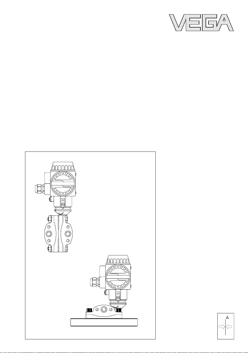
VEGADIF 34
Measuring cell:
ceramic-capacitive
Process fitting:
acc. to DIN 19 213
Standard application:
Differential pressure and flow measurement
with gases, vapours and liquids
VEGADIF 35
Measuring cell:
silicon-piezoresistive with metal separating
diaphragms
Process fitting:
acc. to DIN 19 213
VEGADIF 34
Standard application:
Differential pressure and flow measurement
with gases, vapours and liquids, with differential pressures up to 40 bar and static pressures up to 420 bar
VEGADIF 35
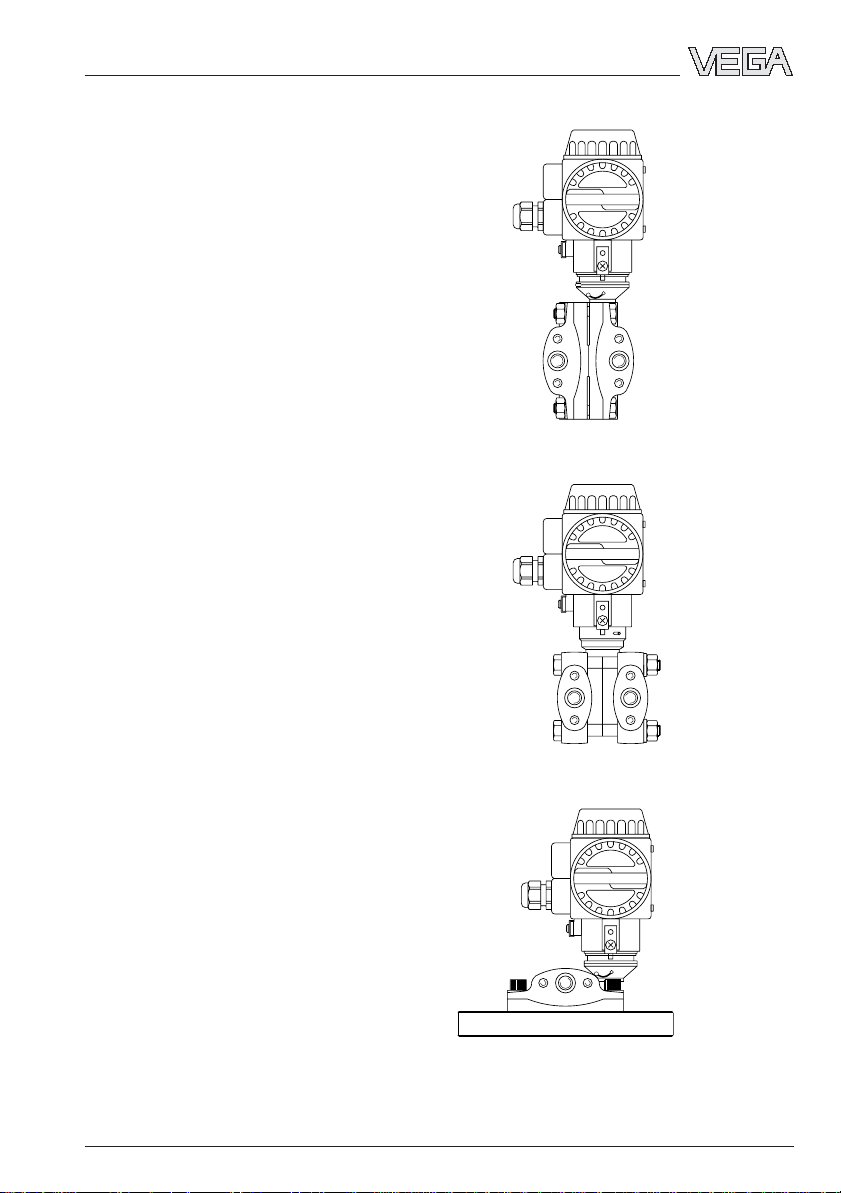
VEGADIF 44
Measuring cell:
ceramic-capacitive
Process fitting:
Plus side flange,
minus side acc. to DIN 19 213
Standard application:
Level measurement in pressurized vessels,
even with suspended solids, abrasive or high
viscosity products
20094-EN-030731
VEGADIF 34 … 51 5
VEGADIF 44
Page 6
VEGADIF 45
Measuring cell:
silicon-piezoresistive with metal separating
diaphragm
Process fitting:
Plus side flange,
minus side acc. to DIN 19 213
Standard application:
Level measurement in pressurized vessels,
even with product temperatures up to 400°C
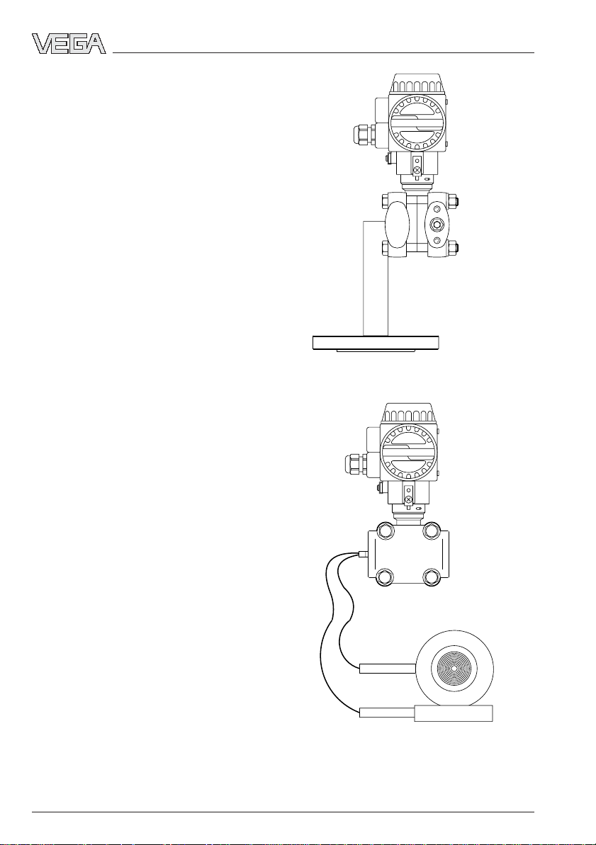
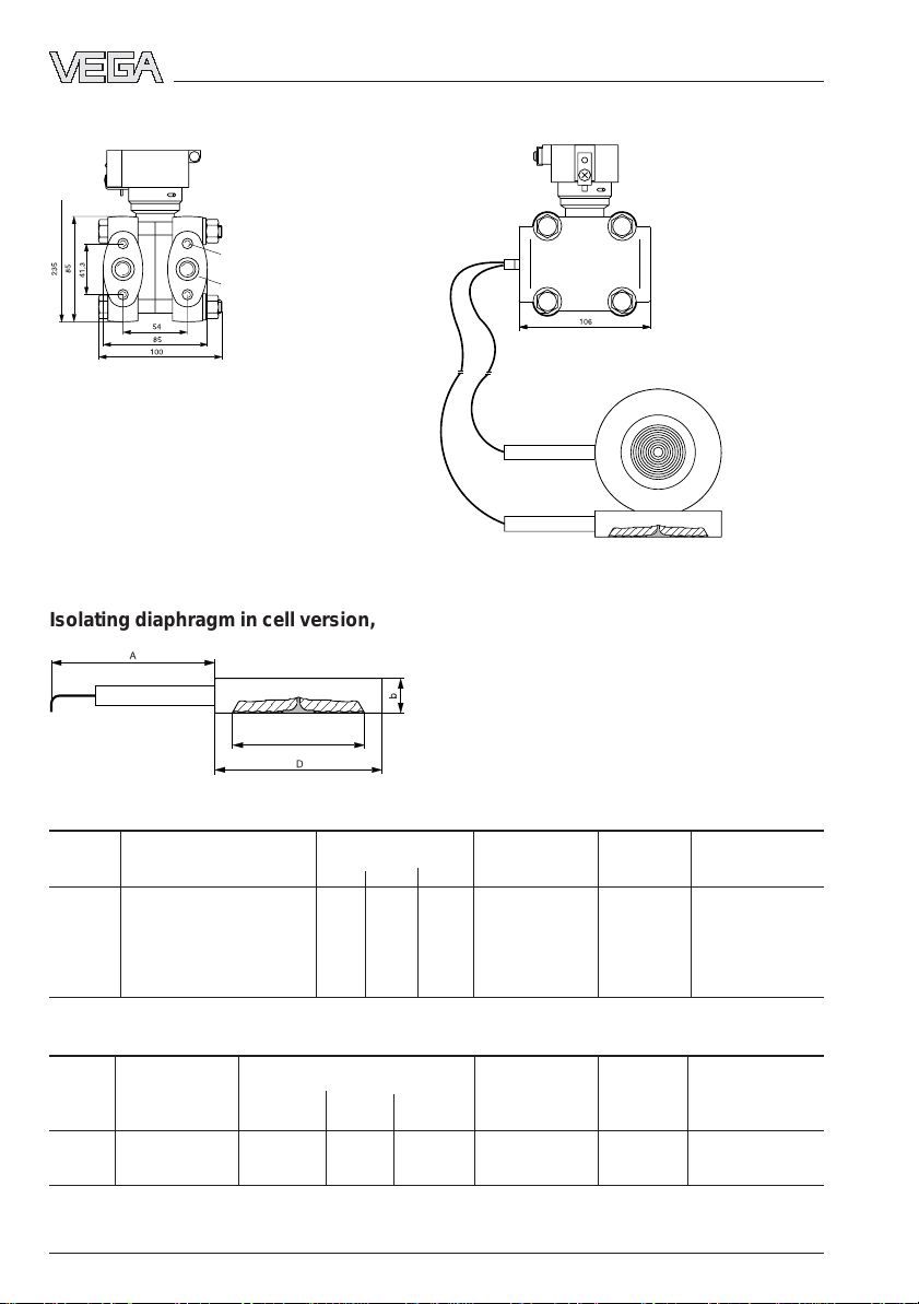
VEGADIF 51
Measuring cell:
silicon-piezoresistive with metal separating
diaphragms
Product description
VEGADIF 45
Process fitting:
Isolating diaphragm in standard series, connected via capillary lines
Standard application:
Level, differential pressure and flow measurement especially with high-viscosity products,
high temperatures and in food processing
industries
Certified instruments are available for application in hazardous areas as well as part of an
overfill protection system acc. to WHG (Water
VEGADIF 51
Resources Act).
6 VEGADIF 34 … 51
20094-EN-030731
Page 7
Product description
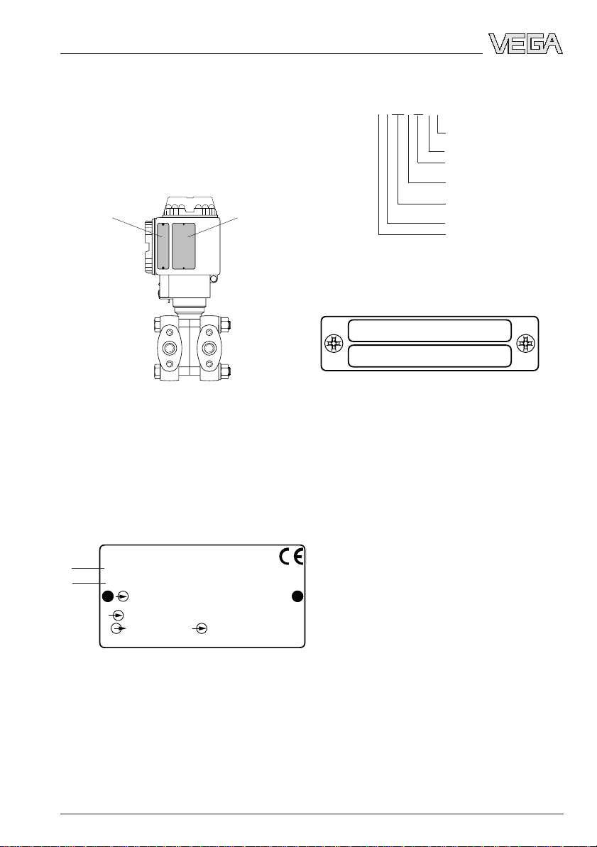
1.3 Type plate
Before installation and electrical connection,
make sure that you are using a suitable differential pressure transmitter. Observe type and
calibration plate which is located as follows:
Calibration plate
Both plates include important data required for
mounting and connection. The configuration
and contents of the plates are explained in the
following example.
Type plate
Product coding example
type DIF35AC4E1VH3C
Process fitting flange 1.4435
Meas. cell seal PTFE
2 ventilation valves,
1 mounting loop
Nominal value calibration
in mbar/bar
Nom. meas. range 160 mbar,
static pressure max. 140 bar
LC display on top
Cable entry Pg 13.5
Configuration of the calibration plate (example)
Cal.
Adj. 0 … 160 MBAR
Calibration range 0 … 160 mbar
Configuration of the type plate (example)
1
2
Order Code
Ser.-No.
p
Pmax
4…20mA U
Mat.
1 Basic data of the order no.
2 Serial number
20094-EN-030731
VEGADIF 34 … 51 7
DIF35 AC4E1 VH 3C
10612892
-160 … 160 mbar
140 bar
1.4571 PTFE
VEGA VEGADIF
Made in
Germany
11,5 … 45 V DC
Page 8

Product description
1.4 Tec hnical data
Mechanical data
Materials, wetted parts
VEGADIF 34
- diaphragm Aluminium oxide ceramic (Al2O3)
- process seal FPM, Hastelloy C4 PTFE-plated, EPDM,
- process fitting carbon steel C22.8 chromized 1.0460,
- ventilation valves stainless steel 1.4571 or 1.4404, Hastelloy C276
VEGADIF 35
- separating diaphragms stainless steel 1.4401
- process seal FPM, NBR, PTFE, FPM for oxygen applications
- process fitting carbon steel C22.8 chromized 1.0460
- ventilation valves stainless steel 1.4571 or 1.4404, Hastelloy C276
VEGADIF 44
- diaphragm Aluminium oxide ceramic (Al2O3)
- process seal FPM, Hastelloy C-4 PTFE-plated, EPDM,
- process fitting (plus side) carbon steel C22.8 chromized 1.0460,
- process fitting (minus side) carbon steel C22.8 chromized 1.0460,
FPM for oxygen application, Kalrez
stainless steel 1.4571 or 1.4404, Hastelloy C276
2.4819, PVDF (PN 10)
2.4819 (only with process fitting Hastelloy)
stainless steel 1.4571 or 1.4404, Hastelloy C276
2.4819
2.4819 (only with process fitting Hastelloy)
FPM for oxygen application, Kalrez
stainless steel 1.4571, stainless steel 1.4571
PTFE coated
Hastelloy C276 2.4819
stainless steel 1.4571 or 1.4404, Hastelloy C276
2.4819
VEGADIF 45
- isolating diaphragm stainless steel 1.4435
- process flange (plus side) stainless steel 1.4435
- process flange (minus side) carbon steel C22.8 chromized 1.0460,
stainless steel 1.4571 or 1.4404, Hastelloy C276
2.4819
VEGADIF 51
- isolating diaphragm stainless steel 1.4435
- process fitting carbon steel C22.8 chromized 1.0460,
stainless steel 1.4571 or 1.4404, Hastelloy C276
2.4819
8 VEGADIF 34 … 51
20094-EN-030731
Page 9

Product description
Materials, non-wetted parts
Common components
- electronics housing and cover Al-die casting (Cu-free), protective coating
Polyester-based, colour yellow RAL 1018,
black RAL … (cover)
- type plates stainless steel 1.4301
- O-rings for cover seal NBR
- screws and nuts for
measuring cell housing or
process fitting carbon steel C22.8
- mounting loop corresponding on the process fitting
carbon steel C22.8, stainless steel 1.4571
1)
VEGADIF 34
- fill fluid of the measuring cell silicone oil, mineral oil, Voltalef 1 A
2)
VEGADIF 35
- measuring cell housing stainless steel 1.4571
- fill fluid of the measuring cell silicone oil, Fluorolube
VEGADIF 44
- fill fluid of the measuring cell silicone oil, mineral oil, Voltalef 1 A
2)
2)
VEGADIF 45 and VEGADIF 51
- measuring cell housing stainless steel 1.4571
- fill fluid of the isolating diaphragm silicone oil, vegetable oil, glycerine,
high temperature oil, oil for oxygen applications
- capillary cable stainless steel 1.4571
- fill fluid of the measuring cell silicone oil, Fluorolube
2)
Weights
VEGADIF 34 approx. 5 kg
VEGADIF 35 4 … 6 kg, depending on the version
VEGADIF 44 8 … 10.5 kg, depending on the flange size
VEGADIF 45 6 … 12 kg, depending on the flange size and
extension length
VEGADIF 51 4 kg plus capillaries and flange isolating
diaphragm
Isolating diaphragm see tables in "1.5 Dimensions - Isolating
diaphragm"
1)
Sea water resistant (salt spray test acc. to DIN 50 021 passed for 504 h)
2)
for applications in pure gases
20094-EN-030731
VEGADIF 34 … 51 9
Page 10
Electrical data
Product description
Connection
Cable entry Pg 13.5 (for cable-ø 9 … 12 mm)
Screw terminals for wire cross section up to 2.5 mm
Ground terminal for wire cross section up to 4 mm
1)
2
2
Supply and signal circuit (4 … 20 mA signal)
Supply voltage
- non-Ex instruments 11.5 … 45 V DC
- Ex instruments 11.5 … 30 V DC
Residual ripple no influence at U
Output signal 4 … 20 mA linear (differential pressure proportio
≤ 4.5 V
SS
nal) or square root (flow proportional changeable)
Resolution better than 6 µA
Current limitation approx. 23 mA
Measuring range overrun 2.8 mA (standard) or 4 mA
Measuring range overrun 20.5 mA acc. to NAMUR
Fault signal (adjustable) 3.6 mA, 21.5 mA, current value
Integration time
2)
0 … 16 s with keys on the instrument
0 … 40 s with HART® handheld
Adjustment period 0.5 … 2.0 s depending on the measuring range
Rise time 0.4 … 1.6 s depending on the measuring range
Heating time 2 s
Connection cable 2-wire
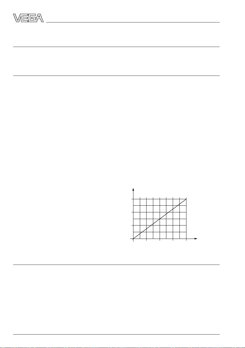
Max. permissible load depending on the power supply
1560
1000
in Ohm
R total
500
Load
0
20 28,5 37 4511,5
Voltage of the external energy UH in Volts
Supply and signal circuit (digital communication signal HART®)
Connection cable 2-wire (communication must not be influenced
by unshielded cables)
Line resistance ≤ 25 Ω/km
Total resistance more than 250 Ω (communication resistance of
at least 250 Ω necessary)
Total capacitance less than 180 nF
Max. length 1000 m
20094-EN-030731
1)
with smaller cable diameter, a suitable seal must be provided by the customer
2)
Adjustment time of 10 % … 63 % of the measuring range final value
10 VEGADIF 34 … 51
Page 11
Product description
Protective measures
Protection IP 65
IP 68 (option for VEGADIF 35, 45 and 51)
Protection class III
CE conformity
VEGADIF 34, VEGADIF 35, VEGADIF 44, VEGADIF 45 and VEGADIF 51 differential pressure
transmitters meet the protective regulations of EMC (89/336/EWG) and NSR (73/23/EWG).
Conformity has been judged acc. to the following standards:
EMC Emission EN 50 081 - 1
Susceptibility EN 50 082 - 2
NSR EN 61 010
Furthermore VEGADIF 35 is subject to the pressure instrument directive (97/23/EG):
- instruments with max. permissible pressures > 200 bar need the CE mark
- instruments with max. permissible pressures ≤ 200 bar do not need the CE mark
NAMUR regulations
Full compliance with the NAMUR regulations NE21, May 1993.
T ransmission reaction
Measuring ranges
VEGADIF 34 and VEGADIF 44
Features Limits Span System pressure Pressure transmission
Nom. liquid
meas. Initial Final value m inimum maxim um Overload Overload in the sensor
ranges value unilateral bilateral
25 mbar -25 mbar 25 mbar 5 mbar 25 mbar 10 bar 10 bar silicone oil
100 mbar -100 mbar 100 mbar 5 mbar 100 mbar 16 bar 2)25 bar 2)silicone oil
500 mbar -500 mbar 500 mbar 25 mbar 500 mbar 100 bar 2)140 bar 2)mineral oil
3000 mbar -3000 mbar 3000 mbar 150 mbar 3000 mbar 100 bar 2)140 bar 2)mineral oil
1)
1)
1)
1)
VEGADIF 35, VEGADIF 45 and VEGADIF 51
Features Limits Span System pressure Pressure transmission
Nom. liquid
meas. Initial Final value m inimum maxim um Overload Overload in the sensor
ranges value unilateral bilateral
3)
10 mbar
40 mbar
160 mbar -160 mbar 160 mbar 10 mbar 160 mbar 140 bar 140 bar silicone oil
1000 mbar -1000 mbar 1000 mbar 50 mbar 1000 mbar 420 bar 4)420 bar 4)silicone oil
6000 mbar -6000 mbar 6000 mbar 300 mbar 6000 mbar 420 bar 4)420 bar 4)silicone oil
40000 mbar3)-40000 mbar 40000 mbar 2000 mbar 40000 mbar 100 bar 420 bar 4)silicone oil
1)
In applications with pure gas Voltalef 1 A
2)
10 bar with process fitting PVDF for VEGADIF 34; 40 bar with process flange for VEGADIF 44
3)
only VEGADIF 35
4)
Note nominal pressure of the flanges
20094-EN-030731
-10 mb ar 10 mbar 2 mba r 10 mbar 140 bar 140 bar silicone oil
3)
-40 mb ar 40 mbar 5 mba r 40 mbar 140 bar 140 bar silicone oil
1)
1)
1)
1)
1)
1)
VEGADIF 34 … 51 11
Page 12
Product description
Minimum pressure
VEGADIF 34, 35 and 44 1 mbar
VEGADIF 45 and 51 10 mbar
abs
abs
Output characteristics
Determination of characteristics fixed point method acc. to VDI/VDE 2600, sheet 4
(corresponds to the limit point adjustment acc. to
DIN 16 086)
Characteristics linear (differential pressure proportional),
changeable to square root (flow proportional)
Accuracy data
1)
Feature Accuracy
2)
Share Share
Instrument hysteresis repeatability
VEGADIF 34 bet ter t han 0.1 % better than 0.05 % better than 0.05 %
VEGADIF 35 bet ter t han 0.1 % better than 0.1 % better than 0.1 %
VEGADIF 44 bet ter t han 0.1 % better than 0.05 % better than 0.05 %
VEGADIF 45 bet ter t han 0.2 % better than 0.1 % better than 0.1 %
VEGADIF 51 bet ter t han 0.2 % better than 0.1 % better than 0.1 %
Log-term stability of the zero signal
3)
better than 0.1 %/12 months (VEGADIF 34 a. 44)
better than 0.2 %/12 months (VEGADIF 35,45,51)
Influence of other actuating variables
Influence of the static pressure
on zero and span better than 0.2 %/PN (VEGADIF 34 and 44)
better than 0.2 %/100 bar (VEGADIF 35, 45, 51)
Electromagnetic compatibility (EMC) interference immunity acc. to NAMUR: 30 V/m
Influence of vibration
5) 6)
better than ±0.1 % acc. to DIN/IEC 68, part 2 - 6
Climatic class GPC acc. to DIN 40 040
Calibration position upright
Influence of the mounting position max. 2 mbar
Temperature influence
Average temperature influence coefficient
of the zero signal
3) 4)
or the output span better than 0.02 %/10 K (+10 … +60°C)
better than 0.1 %/10 K (-40 … +10°C a.
60°C…85°C)
1)
Similar to DIN 16 086
2)
Relating to the nominal measuring range with recommended turn-down of 20 : 1
3)
Relating to the nominal measuring range, reference temperature 25°C, with recommended turn-down limit of
20 : 1
4)
with VEGADIF 45 and 51 without isolating diaphragm or capillaries, see Temperature influence
5)
Relating to the nominal measuring range
6)
with silicon measuring cell measured on the 6000 mbar sensor
12 VEGADIF 34 … 51
20094-EN-030731
Page 13
Product description
Additional temperature influence 1) with VEGADIF 45:
- by isolating diaphragm
Process fitting effective Temperature coefficient
diaphragm-ø [ mbar/1 0 K]
Flange DN 50 PN 40 acc. to DIN 2501,
Seal surface acc. to DIN 2526 form D 46 mm 5.0
Flange DN 80 PN 40 acc. to DIN 2501,
Seal surface acc. to DIN 2526 form D 70 mm 3.0
Flange DN 80 PN 40 with extension 50 mm 70 mm 3.0
Flange DN 80 PN 40 with extension 100 mm 70 mm 3.0
Flange DN 80 PN 40 with extension 150 mm 70 mm 3.0
Flange DN 80 PN 40 with extension 200 mm 70 mm 3.0
Additional temperature influence
1)
with VEGADIF 51:
- by isolating diaphragm
Isolating diaphragm series effecti ve Temperature coefficient
diaphragm-ø [ mbar/10 K]
unilateral bilateral
Cell DN 50 PN 16/400 46 mm 3.0 0.5
Cell DN 80 PN 16/400 70 mm 0.7 0.1
Cell DN 100 PN 16/400 70 mm 0.7 0.1
Cell 3" class 150/2000 2
3
/4"0.7 0.1
Cell 4" class 150/2000 23/4"0.7 0.1
DIN 11 851, nut DN 50 PN 25 46 mm 3.0 0.5
DIN 11 851, nut DN 65 PN 25 52 mm 1.0 0.2
DIN 11 851, nut DN 80 PN 25 71.5 mm 0.7 0.1
DIN 11 851, socket DN 50 PN 25 46 mm 3.0 0.5
DIN 11 851, socket DN 65 PN 25 52 mm 1.0 0.2
DIN 11 851, socket DN 80 PN 25 71.5 mm 0.7 0.1
Clamp 2" PN 25 45 mm 3.0 0.5
Clamp 3" PN 25 71.5 mm 0.7 0.1
DRD flange DN 25 46 mm 1.5 0.25
- by capillary line 2) per m 0.5 mbar/10 K (unilateral)
0.12 mbar/10 K (bilateral)
Operating conditions
Medium characteristics
Aggregate gaseous, vapour, liquid to high viscosity
Condition also abrasive or corrosive (with suitable
1)
Standard values relating to isolating liquid silicone oil
2)
Both capillary lines are supplied with the same length
20094-EN-030731
VEGADIF 34 … 51 13
material for wetted parts acc. to
order code)
Page 14
Product description
Temperatures
Ambient temperature -40°C … +85°C (for indication: -20°C … +85°C)
Medium temperature
- VEGADIF 34 and VEGADIF 44
FPM (Viton, Fluor-caoutchouc) -20°C … +85°C
PTFE (Hastelloy C4, from p
EPDM -40°C … +85°C
≥ 900 mbar) -40°C … +85°C
abs
FPM (Viton for oxygen, oil and grease free) -10°C … +85°C
Kalrez -10°C … +85°C
- VEGADIF 35 and minus side VEGADIF 45
FDM (Viton, Fluor-caoutchouc) -20°C … +85°C
NBR -20°C … +85°C
PTFE, from p
FPM (Viton for oxygen, oil and grease free) -10°C … +85°C
≥ 1 mbar -40°C … +85°C
abs
- plus side VEGADIF 45 and VEGADIF 51
isolating liquid: p
- silicone oil -40°C … +200°C / -40°C … +180°C
≥ 1 bar / 0.05 bar ≤ p
abs
- vegetable oil -10°C … +200°C / -10°C … +120°C
- glycerine +15°C … +200°C / –– –
- high temperature oil -10°C … +350°C / -10°C … +200°C
- oil for oxygen application -40°C … +175°C / -40°C … +80°C
Storage and transport temperature -40°C … +100°C (VEGADIF 34 and 44)
-50°C … +100°C (VEGADIF 35, 45 and 51)
Ex technical data CENELEC
General data
Classification mark EEx ia IIC T4/T6
Intrinsically safe supply and signal circuit
Classification EEx ia IIC
Only for connection to certified, intrinsically
safe circuits with the max. values:
- voltage UO = 30 V
- current IK = 300 mA
- efficiency P = 1 W
Inner effective capacitance C
Inner effective inductance L
Ambient conditions
Ambient temperature around the
oscillator
- temperature class T6 -40°C … +40°C
- temperature class T5 -40°C … +55°C
- temperature class T4 -40°C … +85°C
= 11.2 nF
int
= 0.2 mH
int
1)
abs
< 1 bar
20094-EN-030731
1)
at p
< 1 bar (vacuum range) the isolating liquid boils already at lower temperatures
abs
14 VEGADIF 34 … 51
Page 15
Product description
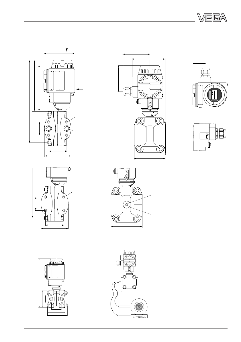
1.5 Dimensions
VEGADIF 34
104
136
150
255
x
81
104
View x
39
80
y
0-500 mbar
2 5 0
41,3
255
41,3
with PVDF flange
VEGADIF 35
M10
7
/16 - 20 UNF
1
/4" - 18 NPT
54
82
M10
7
/16 - 20 UNF
54
82
96
Mounting loop
(optional)
96
PVDF
1
/4" - 18 NPT
View y
Z S
235
41,3
85 (93)
54
85
100 (135)
M10 (M12)
7
/16 - 20 UNF
1
/4" - 18 NPT
106
The values in brackets relate to PN 420
20094-EN-030731
VEGADIF 34 … 51 15
Page 16
VEGADIF 44
;
;;;;;;;
DIN flange DN 80/DN 100 ANSI flange 3"
Product description
M10
7
/16 - 20 UNF
1
/4" - 18 NPT
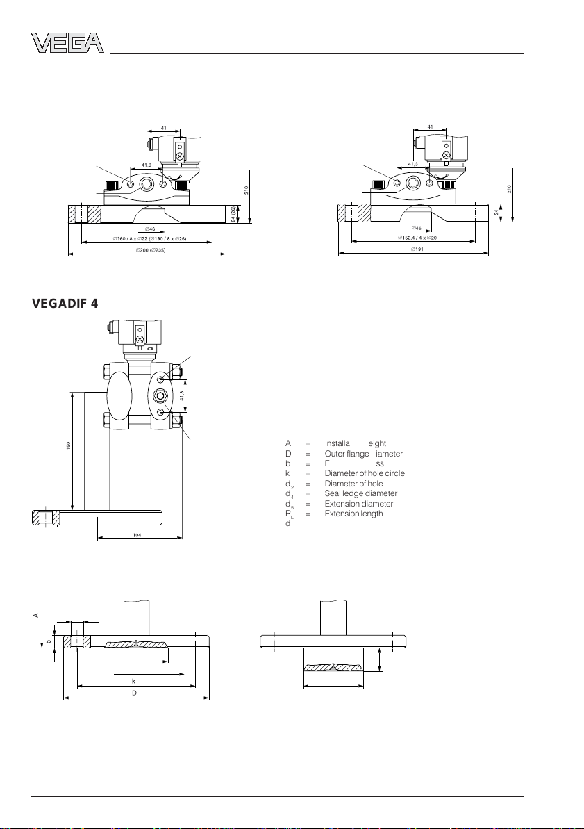
VEGADIF 45
∅
∅ ∅ ∅ ∅
∅ ∅
M10
7
/16 - 20 UNF
1
/4" - 18 NPT
M10
7
/16 - 20 UNF
1
/4" - 18 NPT
A = Installation height
D = Outer flange diameter
b = Flange thickness
k = Diameter of hole circle
d2= Diameter of hole
d4= Seal ledge diameter
d5= Extension diameter
RL= Extension length
dM= Diaphragm diameter
∅
∅ ∅
∅
d
2
d
M
d
4
d
5
L
R
16 VEGADIF 34 … 51
20094-EN-030731
Page 17
Product description
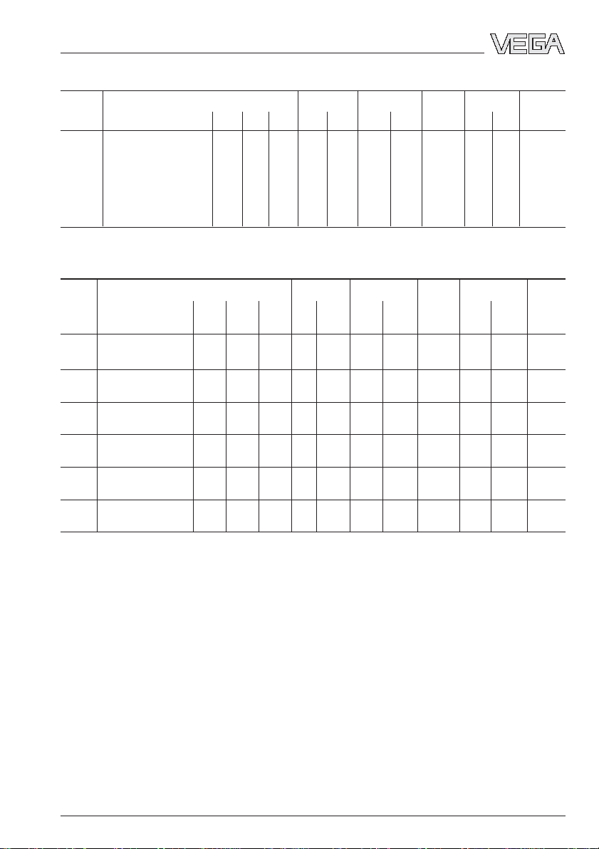
Flange connection acc. to DIN 2501, seal ledge acc. to DIN 2526 form D
Order Flange Holes Seal ledge Dia. Exten sion Ins tall.
code Size / Nominal pre ssure D b k No. d2d
dMR
4
d5dMheight A
L
B DN 50 / PN 40 165 20 125 4 18 102 46 – – –– –– 360
C DN 80 / P N 40 200 24 160 8 22 138 70 –– –– –– 360
D DN 80 / P N 40 200 24 160 8 22 138 –– 50 76.5 70 360
E DN 80 / PN 40 200 24 160 8 22 138 –– 100 76.5 70 360
F DN 80 / PN 40 200 24 160 8 22 138 –– 200 76.5 70 360
G DN 100 / PN 40 235 26 190 8 26 162 70 –– 76.5 70 360
Flange connection acc. to ANSI B 16,5
Order Flange Holes Seal ledge Dia. E xtension Install.
code Size / Nom inal pr. D b k N o. d
in lb/sq in in/mm in/mm in/mm in/mm in/mm in/mm in/mm in/mm in/mm A
P 2 / 150 6/152
3
/4 /43/4/43/4/35/8/13/4/ –– – – –– 14.2/
19.5 120.7 20 92 46 360
R 3 / 150 8.25/
15
/16 /6/ 43/4/5 /23/4/ –– – – –– 14.2/
191 24 152.4 20 127 70 360
S 3 / 150 8.25/
15
/16 /6/ 43/4/5/–– 2/ 3/23/4/ 14.2/
191 24 152.4 20 127 50.8 76.5 70 360
T 3 / 150 8.25/
15
/16 /6/ 43/4/5/–– 4/ 3/23/4/ 14.2/
191 24 152.4 20 127 101.6 76.5 70 360
U 3 / 150 8.25/
15
/16 /6/ 43/4/5/–– 8/ 3/23/4/ 14.2/
191 24 152.4 20 127 203.2 76.5 70 360
W 4 / 300 10/ 1
1
/2 /78/9/814/16/62/9/23/4/ –– – – –– 14.2/
254 32 200.1 23 158 70 360
d4d
2
R
M
d5d
L
height
M
20094-EN-030731
VEGADIF 34 … 51 17
Page 18
;
;;;;;;;
VEGADIF 51
;
7
/16 - 20 UNF
1
/4" -
18 NPT
Isolating diaphragm in cell version, AA … CR
Product description
d
M
acc. to DIN 2501
Order Socket Cell Min. mounting Max. Weight
code Siz e/Nomi nal pre ssure D b d
distance A pressure approx.
M
AA DN 50 PN 16 102 20 46 130 400 bar 2.6 kg
AK DN 80 PN 16 138 20 70 130 400 bar 4.6 kg
AM DN 80 PN 16 PTFE 138 20 70 130 400 bar 4.6 kg
AN DN 80 PN 16 Hastelloy 138 20 70 130 400 bar 4.6 kg
AR DN 100 PN 16 158 20 70 130 400 bar 6.2 kg
acc. to ANSI 16.5
Order Socket Cell Min. mounting Max. Weight
code Siz e/Nom p r. D b d
in / lb sq in in/mm in/mm in/mm A in/mm lb/sq in
M
CK 3 / 150 71/2 / 1343/4 / 20 23/4 / 70 5 / 130 – – 4.5 kg
CR 4 / 150 81/4 / 1583/4 / 20 23/4 / 70 5 / 130 2500 6.2 kg
18 VEGADIF 34 … 51
distance pressure approx.
20094-EN-030731
Page 19
Product description
;;;;;;;;;;
;;;;;;;;;;
;;;;;;;;;;
;;;;;;;;;;
;;;;;;;;;;
;;;;;;;;;;
;;;;;;;;;;
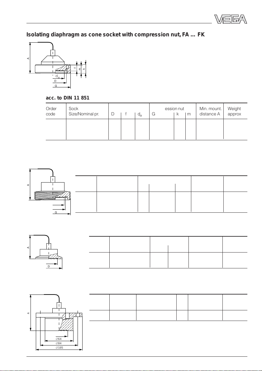
Isolating diaphragm as cone socket with compression nut, FA … FK
d
M
acc. to DIN 11 851
Order Socket Cell Compression nut Min. mount. Weight
code Size /Nomin al pr. D f dMG k m distance A approx.
FA DN 50/PN 25 68 11 46 Rd78x
FE DN 65/PN 25 86 12 52 Rd95x1/6" 25 21 120 4.0 kg
FK DN 80/PN 25 100 12 71.5 Rd110x1/4" 29 25 120 5.1 kg
1
/6" 22 19 120 2.2 kg
Isolating diaphragm as threaded socket, GA … GK
acc. to DIN 11 851
Order Socket Threaded socket Min. mounting Weight
code Size /Nomin al pr. d1GdMdistance A approx.
d
1
d
M
GA DN 65/PN 25 66 Rd95x1/6" 52 110 3.4 kg
GK DN 80/PN 25 91 Rd110x1/6" 71.5 110 4.0 kg
GA DN 50/PN 25 60 Rd78/
1
/6" 46 110 1.8 kg
Isolating diaphragm as Clamp, HA and HK
Order Socket Terminal socket Min. mounting Weight
code Size /Nomin al pr. D d
d
M
HA DN 2" PN 40 64 46 100 1.4 kg
HK DN 3" PN 40 91 71.5 100 2.4 kg
M
distance A approx.
Isolating diaphragm as DRD flange, KE
Order Socket Dimensions Min. mounting Weight
code Nomi nal pr. dMdistance A approx.
A
d
M
∅64
∅84
∅105
20094-EN-030731
VEGADIF 34 … 51 19
KE PN 25 see drawing 46 100 1.5 kg
Page 20
Product description
;
;
;
;
;
;
;
;
;
;
;
;
;
;
;
;
;
;
;
;
;
;
;
;
;
;
;
;
;
;
;
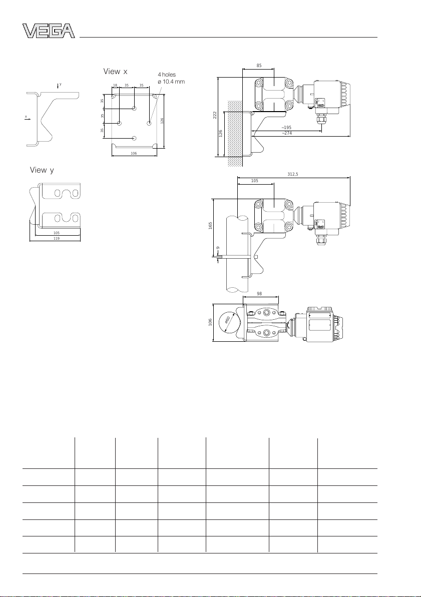
Mounting bracket Installation instructions
;;;;;;
;;;;;;
;;;;;;
;;;;;;
;;;;;;
;;;;;;
;;;;;;
;;;;;;
;;;;;;
;;;;;;
;;;;;;
;;;;;;
;;;;;;
;;;;;;
;;;;;;
;;;;;;
;;;;;;
;;;;;;
;;;;;;
;;;;;;
;;;;;;
;;;;;;
;;;;;;
;;;;;;
;;;;;;
;;;;;;
;;;;;;
;;;;;;
;;;;;;
;;;;;;
;;;;;;
ø60
85
~195
~274
105
312,5
98
x
View y
View x
y
18
35 35
4 holes
ø 10.4 mm
35
35
126
35
222
126
106
105
119
165
9
106
+
Z S
-
+
Z S
-
1.6 Approvals
For these applications the appropriate official documents (test reports, test certificates and
conformity certificates) have to be noted. These are supplied with the appropriate instrument.
Overview of approvals being prepared or applied for
Approval CENELEC CENELEC PTB-Zone 0 FM FM WHG
Type and non incentive safe
VEGADIF 34 • • • • • •
VEGADIF 35 • • • • • •
VEGADIF 44 • • • • • •
VEGADIF 45 • • • • • •
VEGADIF 51 • • • • • •
20 VEGADIF 34 … 51
EEx ia IIC EEx d IIC EEx ia IIC Explosion proof Intrinsically
20094-EN-030731
Page 21

Mounting
2 Mounting
2.1 Checking the operating
conditions
VEGADIF is a rugged transmitter for precise
differential pressure, level and flow measurement. The accuracy of the measurement
mainly depends on the correct installation and
connection of differential pressure lines.
Detailed information on differential pressure
measurement in corrosive products as well as
further information on wiring and coordination
of valves, measuring lines and components is
provided in the VDI/VDE regulations 3512 as
well as DIN 19 201 and DIN 1952. Further
information on level measurement is stated in
the VDI/VDE regulations 3519.
The implemented differential pressure transmitter must meet the technical and safety
requirements of the application. For this reason, double-check the type plate, calibration
plate and order code regarding the following
data:
Nominal pressure
The nominal pressure rating of VEGADIF must
be above the operating pressure of the process.
Measuring range
The measuring range is calibrated (factory
setting) according to the order data. The
pressure values adjusted for zero and span
are documented on the calibration plate. The
values must cover the application. If an adaptation is necessary, this should be carried out
acc. to section 4 Set-up.
Materials of wetted parts
The materials of wetted parts must be sufficiently resistant. Use the respective material
tables to check this. A table is provided in the
product information manual of VEGADIF, for
more information we recommend the VEGA
resistance lists.
Ambient temperature
The ambient temperature at the installation site
must be in the range of -40°C … +85°C. The
surface temperature of the electronics housing
must not exceed +85°C. It is therefore important to make sure that the temperature of the
electronics housing does not go above +85°C
through radiated heat from neighbouring
instruments or other system equipment. If
there is the danger of this happening,
VEGADIF should be protected against this
heat radiation. If temperatures below
-40°C are expected at the installation, the
transmitter should be installed in a temperature insulated and heatable protective box. If
there is the danger of medium or condensate
freezing in the process connection or on the
measuring cell, the transmitter must be installed in a warmer place or in a heatable
protective box for the process connections
and process seals. Similar measures should
be taken to protect the pressure lines.
Product temperature
The permissible product temperature depends on the process seal, the measuring cell
and the isolating liquid. When VEGADIF 45 or
51 are used, note that the product temperature can differ between plus and minus side.
Humidity
Mount horizontally installed instruments with
the cable entry pointing downward, in order to
avoid moisture ingress. To facilitate this, the
sensor housing can be rotated by approx.
350°. With vertically installed instruments, loop
the connection cables in a bow pointing downward towards the instrument housing, so that
rain and condensation water can drain off.
This applies particularly when mounting outdoors, in humid areas (e.g. by cleaning processes) or on cooled or heated vessels.
20094-EN-030731
VEGADIF 34 … 51 21
Page 22

Mounting
2.2 Pre-installation
Selection of the installation location
Especially under extreme ambient conditions,
selection of a suitable mounting site is decisive
for the
- quality of the measurement
- lifespan of the transmitter
- level of maintenance expenses.
Please observe the following rules:
Installation level
• Below the min. level for level measurements
(the diaphragm or the isolating diaphragm
must be completely covered by the medium).
• Above the pressure tapping point for
measurement of gases.
• Below the pressure tapping point for meas-
urement of vapours and liquids.
Mounting location
• Mount the transmitter as near as possible to
the pressure tapping point.
• Keep impulse lines as short as possible.
• Mounting and maintenance work should be
carried out without obstructions.
• The transmitter, the tapping points, the
impulse lines and the valves should be
easily accessible.
• If available, the mounting site should provide a good view to the LC display.
Adaptation of the transmitter
To optimally adapt your VEGADIF to the installation site, the following measures can be
carried out:
Rotate the electronics housing
After loosening the locking screw below the
electronics housing, the housing can be rotated by approx. 330°. A stop prevents further
turning. By this means the terminal compartment can be set to an optimum position for
cable entry or the LC display to an optimum
reading position.
Fig. 2.1 Loosen the locking screw
When the best position is reached, tighten the
locking screw again.
Ambient influences
• Keep vibration and shock to a minimum.
• Avoid corrosive ambient atmosphere.
• Reduce condensation to a minimum.
Note:
Under unfavourable ambient conditions, a
protective housing is recommended.
Fig. 2.2 Fastening the locking screw
22 VEGADIF 34 … 51
20094-EN-030731
Page 23

Mounting
Rotating the display
If the integrated display is not correctly positioned it can be rotated in 90° steps after
opening the housing cover.
Avoid exposure of the electronics compartment and carry out these measures if possible
in a workshop.
1 Unscrew the display cover
2 Push the protruding clamp with a screw-
driver outwards
3 Tilt the display in this position and take
it out
Note
Do not turn more than 2 x 90° to the left or
right, otherwise the connection cable will be
damaged.
5 Insert the display into the clamp until it
snaps in
6 Screw the cover back on
Remove the protective cover
Transmitter or isolating diaphragm are provided with protective plastic covers. Remove
them before installation.
4 Rotate display as needed
20094-EN-030731
VEGADIF 34 … 51 23
Page 24

Mounting
2.3 Mounting
2.3.1 VEGADIF 34, 35 and 51
As a rule, the differential pressure transmitter
must be firmly mounted. There are three
mounting options for VEGADIF 34, 35 and 51:
- pipe mounting (2“ pipe)
- wall mounting
- mounting on a valve block
Simply hanging the transmitter on the pressure lines is not recommended and is not
permitted with capillary lines.
For correct mounting, VEGA offers a universal
mounting kit consisting of:
- a mounting bracket
- a pipe shackle for 2“ pipes (up to outer-ø
63 mm)
- two hexagon nuts M8 with plain washers
- four hexagon screws (7/16 UNF or
M10 x 182))
For easy removal of the transmitter, a three or
five valve manifold (ball valve fitting) can be
connected 1).
In this case, the valve block can be mounted
with the mounting kit to a pipe or wall instead
of the transmitter. This mounting option ensures easy mounting and dismounting of the
transmitter without interrupting the process.
The impulse lines can be sealed via the valves
and the manifold with the connected impulse
lines can be left in place after removal of the
transmitter.
1)
Pipe mounting
Use the complete mounting kit material and
the take note of the following procedure:
1 Hold the mounting bracket in the required
direction on the tube.
2 Insert the u-bolt around the pipe through the
holes of the mounting bracket.
3 Screw the two hexagon nuts to the u-bolt
and fasten the bracket to the pipe by tightening the nuts.
4 Fasten the transmitter to the bracket (the
screws with plain washers pass through the
holes of the bracket into the thread).
Mounting on vertical pipe
approx. dimensions in mm
105
165
9
312,5
+
Z S
-
+
Z S
-
1)
not with VEGADIF 51
2)
M12 x 18 with 420 bar version of VEGADIF 35
24 VEGADIF 34 … 51
20094-EN-030731
Page 25

Mounting
Mounting on horizontal pipe
Wall mounting
Use the following mounting kit material:
- mounting bracket
- four hexagon screws
Provide the following material:
- four screws with suitable plugs
Note the following procedure:
1 Screw the mounting bracket to the wall by
using the screws with the suitable plugs.
2 Screw the transmitter to the bracket (the
screws with plain washers pass via the
holes of the bracket into the thread).
Mounting with valve block
1)
The valve block is fastened by pipe or wall
mounting as described above.
Procedure:
1 Fasten bracket to a pipe or wall.
2 Screw the valve block to the mounting
bracket with two hexagon screws and plain
washers.
The transmitter is normally flanged to the valve
block just before setting up the measurement
loop.
2.3.2 VEGADIF 44 and 45
The following instructions are for VEGADIF 44,
however, they are also applicable to VEGADIF
45.
Open vessel
The minus side of the transmitter is open to
atmospheric pressure. Therefore the open
process connection of the minus side should
point downwards.
Max.
Min.
P
atm
Atmospheric pressure on the minus
side of the transmitter
20094-EN-030731
VEGADIF 34 … 51 25
1) not with VEGADIF 51
Page 26

;
;
;
;
Mounting
Closed vessel
The minus side of the transmitter is connected
via an impulse line with the vessel and receives the overlaid pressure. The pressure
tapping point must be above the max. level.
The impulse line should equipped with a block
valve.
Block
valve
Steam trap
Block
valve
If the static pressure is caused by steam
above the product, the minus side is connected via a condensate column. Before
opening the block valve, the impulse line must
be filled via the condensation pot.
2.3.3 Isolating diaphragm mounting
with VEGADIF 51
The two isolating diaphragms connect the
pressure transmitter with the process. The
dimensions of the cell isolating diaphragm are
dependent on the respective standard flange.
The fastening is made by means of a suitable
blind flange. Depending on the flange, a seal
acc. to DIN 2690 or ANSI B 16.5 must be
used.
Mounting
Blind flange
;;;;;;;;;;;;;;;;;;;;;;;;;;
Isolating diaphragm
Seal
Measurement
loop connection flange
Vessel wall
Level measurement
;;;;;;;;;;;;;;;;;;;;;;;;;;
;;;;;;;;
;;;;;;;;
Block
Condensation pot
valve
Condensate
Steam
Max.
Min.
Min.
Recommended mounting
Block
valve
26 VEGADIF 34 … 51
Condensation outlet
20094-EN-030731
Page 27

Mounting
Only permitted if no vacuum can occur (not
even short-term occurrence).
Differential pressure measurement
-+
Flow measurement
+
-
Avoid buildup in the form of solids or adhesive
products on the isolating diaphragm when
mounting to horizontal pipelines. We recommend positioning the flange connections on
top of the pipe.
20094-EN-030731
VEGADIF 34 … 51 27
Page 28

3 Electrical connection
Electrical connection
3.1 Connection instructions
The electronics of the pressure transmitters
requires a supply voltage of 11.5 … 45 V DC.
Supply voltage (DC voltage) and current
signal are carried over the same two-wire
connection cable to the terminals.
The supply voltage is provided via a separate
power supply unit:
- power supply unit
(e.g. VEGASTAB 690)
- processing unit with integrated DC voltage
source (e.g. active PLC input)
- VEGAMET series 500 or 600 signal conditioning instrument, VEGALOG 571 processing system or VEGADIS 371 indicating
instrument
Make sure that the external energy source is
reliably separated from the mains circuits acc.
to DIN VDE 0106, part 101. VEGA instruments
meet this requirement and protection class III
is therefore maintained.
For electrical connection note the following
instructions:
- The connection must be made acc. to the
specific national installation standards (e.g.
in Germany acc. to the VDE regulations).
- The wiring between transmitter and power
supply can be carried out with standard
two-wire cable.
- If strong electromagnetic interference is
expected, screened cable is recommended. The screening must be earthed at
one sensor end.
- The connection cable for the external energy must never be connected to terminal 3
of the terminal block or to the test plug connection via terminal 1 of the terminal block
(danger of damaging the electronics).
- After electrical connection, housing cover
and cable entry must be tightened to avoid
moisture ingress in the connection compartment
3.2 Load resistance
Various instruments can be connected to the
signal output of the pressure transmitter, e.g.:
- remote transmission systems
- computers
- indicating instruments
- recorders
- controllers
- contactors etc.
The total resistance of the connected instruments and the connection cable must not
exceed the value of the max. load resistance.
The load resistance consists of the line resistance RL, adjustment resistance RX, and the
resistance of the processing system and/or
indicating instrument.
This max. load resistance depends on the
voltage of the external energy and can be
calculated acc. to the following formula:
US – U
R
= –––––––––
Lmax
R
Lmax
US= power supply
UKl= terminal voltage
I
max
The following load diagram is used for simplified determination of this value:
1560
1000
in Ohm
500
total
Load R
K
I
max
= max. load resistance
= max. current (approx. 23 mA)
0
20 28,5 37 4511,5
Power supply US in Volt
20094-EN-030731
28 VEGADIF 34 … 51
Page 29

Electrical connection
3.3 Connection
Electronics powered by a power supply unit
Processing via an indicating instrument.
Ammeter for local testing
4 ... 20 mA
+
+
-
Ground terminal
Transmitter
terminals
2-3
1
U
Kl
Screen
1)
R
L
analogue / digital
indicating instrument
e.g. VEGADIS
U
A
4 … 20 mA
U
S
-
~
+
Power supply
Electronics powered by a VEGA signal conditioning instrument or a PLC with active
input circuit
Processing is made via the PLC or the VEGAMET signal conditioning instrument.
Ammeter for local control
4 ... 20 mA
2-3
1
+
+
-
U
Transmitter
terminals
R
L
Kl
Screen
4 … 20 mA
PLC active
or
0/4 … 20 mA
–
U
S
+
DISBUS
!
Ground terminal
1)
US= Power supply
UA= Voltage loss in the indicating instrument
UKL= Terminal voltage (supply voltage)
1)
Connect screen, here, ground terminals on the
housing exterior acc. to regulations. The two
terminals are galvanically connected.
RL= Resistance processing systems and connec-
tion cable (load resistance)
Note:
An ammeter for local testing of the output current can be connected to terminals 1 and 3 as well
as their tag. This measurement can be made during operation without interrupting the supply
cable.
20094-EN-030731
VEGADIF 34 … 51 29
Page 30

Electrical connection
3.4 Ex applications
Applications in Ex areas require the use of
approved instruments.
For these applications, the appropriate documents (test reports, test and conformity certificates) must be noted. These are supplied with
the appropriate instrument.
Please note the attached approval documents
(yellow binder) and especially the attached
safety data sheet.
In Ex applications, the power must be provided only via an intrinsically safe circuit.
There are the following options:
- VEGAMET signal conditioning instrument in
Ex version
- non-certified VEGAMET signal conditioning
instrument with VEGA safety barrier type
145
- Ex separator (e.g. VEGATRENN 149 Ex)
- VEGADIS 371 indicating and power supply
unit in Ex version.
The legal documents of these instruments
must also be noted.
Application with power supply via Exseparator, e.g. VEGATRENN 149 Ex
The processing is done by an indicating instrument in non-Ex area.
Ex application with power supply via VEGA
non-Ex signal conditioning instrument
with safety barrier type 145
The processing is done by the signal conditioning instrument in the non-Ex area.
Ex-area
4 ... 20 mA
Terminals
2-3
1
VEGADIF
+
+
-
U
Kl
Non-Ex area
Safety barrier
type 145
VEGAMET in
non-Ex version
Note
- Carry out the adjustment only with connected safety barrier (reason: the current
consumption of approx. 300 µA is considered).
- When connecting a VEGADIS 11 Ex the
regulations for wiring of intrinsically safe
circuits should be noted.
Determination of the cable length in the
ia IIC circuit
The sum of the inner capacitances and inductances of the components must not exceed the
max. permissible values of the ia IIC circuit.
4 ... 20 mA
2-3
1
+
+
-
U
Kl
Ex area
Terminals
VEGADIF
VEGADIS 11
Non-Ex area
e.g. Ex-separator
VEGATRENN
149 Ex
-
U
S
+
4…20 mA
Processing, e.g.
indicating instrument
=
~
Example:
ia IIC circuit Pressure 1 pce. Cable
max. total transmitter overv. arrester L
L
ext/Cext
L
int/Cint
L
int/Cint
0.5 mH 0.2 mH 0.13 mH 0.17 mH
56 nF 11.2 nF 1 nF 44.8 nF
1)
Typical values for unscreened two-wire cables:
int/Cint
1)
L‘ = 0.00065 mH/m; C‘ = 0.00012 nF/m
30 VEGADIF 34 … 51
20094-EN-030731
Page 31

Electrical connection
Calculation of L
L
(cable) = L
int
transmitter) – L
of the cable:
int/Cint
(ia IIC circuit) – L
ext
(overvoltage protection)
int
int
(pressure
= 0.5 mH – 0.2 mH - 0.13 mH
= 0.17 mH
C
(cable) = C
int
transmitter) – C
(ia IIC circuit) – C
ext
(overvoltage protection)
int
int
(pressure
= 56 nF – 11.2 nF - 1 nF
= 44.8 nF
Calculation of the cable length:
0.17 mH
I = –––––––––– • m = 262 m
0.65 µH
44.8 nF
I = ––––––––––– • m = 373 m
120 pF *
To be on the safe side, the cable length in this
example should not exceed a value of 250 m.
20094-EN-030731
VEGADIF 34 … 51 31
Page 32

4 Set-up
Set-up
4.1 Adjustment structure
The differential pressure transmitters can be
set up with
- the PC and the VEGA adjustment program
VVO,
- the HART® handheld or
- the integrated 4-key adjustment elements.
Adjustment program VV O
The adjustment program VVO (VEGA Visual
Operating) on the PC allows very convenient
sensor adjustment. The PC communicates via
the interface converter VEGACONNECT 2 with
the sensor. During adjustment, a digital adjustment signal is superimposed on the signal
and supply cable. The adjustment can be
carried out a any point along the signal cable,
and of course also directly on the sensor.
HART® handheld
Beside the PC and the 4-key adjustment elements, the sensors can be also adjusted with
the HART® handheld.
4-key adjustment elements with LCdisplay
If you have neither a PC nor a HART
handheld, the sensors can be also set up
directly with the integrated 4-key adjustment
elements.
®
4.2 Adjustment with the 4-key adjustment element
LC display in operating mode
According to the ordered version, your
VEGADIF is provided with an integrated LCdisplay. This display can be retrofitted or
removed. The display is located below the
upper housing cover behind a glass pane.
The LC display provides the following information in the adjustment mode:
Span indication during
full adjustment
Appropriate
pressure value
s
5 .0 0 0
z
Zero indication during
empty adjustment
Position of
zero
Bar graph measuring
span = span – zero
LC-display
The following examples show possible indication values.
Example 1: Meas. range -0.5 … 1.5 bar, LCD
in operating mode
Position of
span
∆p
-0,5 bar
0 bar
0,5 bar
1 bar
1,5 bar
32 VEGADIF 34 … 51
Display I
- 0 .5 0 0
- 0 .0 0 0
0 .5 0 0
1 .0 0 0
1 .5 0 0
4 mA
8 mA
12 mA
16 mA
20 mA
20094-EN-030731
Page 33

Set-up
Example 2: Meas. range 0 … 10 bar
∆p
0 bar
2,5 bar
5 bar
7,5 bar
10 bar
Display I
0 .0 0
2 .5 0
5 .0 0
7 .5 0
1 0 .0 0
4 mA
8 mA
12 mA
16 mA
20 mA
4-key adjustment elements
Your VEGADIF is provided with the following
direct adjustment elements:
- four adjustment keys
- one step switch
The adjustment keys are located below a
sliding cover laterally on the electronics housing. The slider cover is marked with z (zero)
and s (span) and can be moved after loosening the recessed head screw. When the sliding cover is moved, two adjustment keys are
exposed; when the sliding cover is rotated, all
four adjustment keys are exposed.
+
Z S
-
First of all the sliding cover exposes 2 keys
and then all four keys
Via these four keys in conjunction with the LCdisplay, you can carry out the most important
adjustments such as zero, span and bias
pressure directly on the transmitter.
++
ZS
-
If you have a VEGADIF without LC-display,
connect an ammeter with measuring range
0 … 20 mA (e.g. digital multimeter) to the
terminal and tag 1. A precision ammeter is
recommended for exact adjustment. Push the
keys with a small screwdriver.
The second adjustment element, the step
switch, is located below the LC-display; to use
it, remove the display, as described under
„2.2 Pre-installation“.
The step switch below the LC-display
The settings on the step switch mean:
- 0 Adjustment with PC or HART®, there-
fore damping adjustable from 0 … 40 s
- 2 Damping 0.5 s linear
- 3 Damping 1.0 s linear
- 4 Damping 2.0 s linear
- 5 Damping 4.0 s linear
- 6 Damping 8.0 s linear
- 7 Damping 16.0 s linear
- 8 Adjustment with PC or HART®, there-
fore damping adjustable from 0 … 40 s
- 9 Damping 0 s extracted by root
- A Damping 0.5 s extracted by root
- B Damping 1.0 s extracted by root
- C Damping 2.0 s extracted by root
- D Damping 4.0 s extracted by root
- E Damping 8.0 s extracted by root
- F Damping 16.0 s extracted by root
Current I
Current I
∆p/p
20094-EN-030731
∆p
linear extracted by root
VEGADIF 34 … 51 33
Page 34

Set-up
Display zero
1 Push +z or –z key
2 Monitor the displayed value and release the
key again.
After approx. 2 s the indication resets automatically to operating mode.
Example for display of zero:
Meas. range D is pl ay
-3…0 bar
0…1,5 bar
2,5…-0,5 bar
Display span
1 Push +s or –s key
2 Monitor the displayed value for s and re-
lease the key again
The display resets automatically to operating
mode after approx. 2 s.
1)
z
- 3 .0 0 0
z
0 .0 0 0
z
2 .5 0 0
Data of the default setting
Measuring range
Your VEGADIF is calibrated acc. to the order.
The calibration data is stated on the calibration
plate, e.g. 0 … 1000 mbar.
For this measuring range:
- The 4 mA signal is always assigned to the
first pressure value (in the example
0 mbar).
- The 20 mA signal is always assigned to the
second pressure value (in the example
1000 mbar).
Check if the calibrated measuring value corresponds to the application and, if necessary,
adapt acc. to the following paragraph „Adjustment“.
Integration time
A factory set integration time of 0 s is supplied. Via the step switch this time can be
changed from 0 … 16 s, with the PC to
0 … 40 s, to achieve an increased smoothing
of the output signal.
Output characteristics
The factory setting is linear characteristics. A
square root output can be selected with the
step switch.
Examples for display of span:
Meas. range D is pl ay
-3…0 bar
s
0 .0 0 0
Electronics replacement
The calibration data is saved in the EERPOM
memory of the electronics. Always check the
data when replacing the electronics and
modify, if necessary.
Adjustment
0…1,5 bar
2,5…-0,5 bar
1)
This setting effects an inversion of the current
output
34 VEGADIF 34 … 51
s
1)
1 5 0 0
- 5 0 0 .0
First note the adjustment range for zero and
span. The values are stated under „1.4 Technical data - Transmission reaction“. Make sure
that your requested values are within the
possible adjustment ranges.
20094-EN-030731
Page 35

Set-up
Two adjustment methods are available
- adjustment without pressure (dry)
- adjustment with pressure (wet)
The dry adjustment can be carried out in the
workshop before mounting or after mounting
at the measuring site. During adjustment be-
fore mounting, make sure that the position of
the transmitter corresponds to the intended
installation position. This is particularly necessary for VEGADIF 45 and 51 with isolating
system or capillaries. For sensors without
display you should use a precision ammeter
(class 0.03 or better) to adjust the current
output.
Adjustment without pressure (dry)
Reduce zero
1 Push the z– key twice and hold it pushed.
2 Note the current change.
3 Release the z- key when the requested
current value is reached.
4 The display resets automatically to operat-
ing mode after approx. 2 s and the adjusted
value is saved.
Example:
given: 0 … 1000 mbar, (z = 0 mbar, s = 1000
mbar)
z to be changed to: z = -500 mbar
Increase zero
Push the z+ key twice and hold it pushed. The
procedure is the same as for reduce zero.
Example:
given: 0 … 1000 mbar, (z = 0 mbar, s = 1000
mbar)
to be changed to: s = 500 mbar
Push the s- key and hold it pushed until
500 mbar are adjusted.
Adjustment range (editing limits) of zero and
span:
-110 … +110 % of the nominal range
Adjustment with pressure (wet)
When adjusting with pressure, VEGADIF must
be connected to a variable pressure source.
These are the options:
- connect to a pressure calibrator
- connect directly to the process
Adjust zero with display
1) Set pressure for zero precisely (e.g.
0 bar) and check via the display.
2) Push the z+ and z– keys simultaneously.
The pressure (e.g. 0 bar) corresponds to the
output current 4 mA.
Adjust span with display
1) Set pressure for span precisely (e.g.
1 bar) and check via the display.
2) Push the s+ and s– keys simultaneously.
The pressure (e.g. 1 bar) corresponds to the
output current 20 mA.
Reduce span
1 Push the s– key twice and hold it pushed.
2 Note the current change.
3 Release the s- key when the requested
value is reached.
4 The display resets automatically to operat-
Adjust zero without display
1) Set pressure for zero precisely (e.g.
0 bar) and check via an external pressure
calibrator.
2) Push the z+ and z– keys simultaneously.
ing mode after approx. 2 s and the adjusted
value is saved.
The pressure (e.g. 0 bar) corresponds to the
output current 4 mA.
20094-EN-030731
VEGADIF 34 … 51 35
Page 36

Set-up
Adjust span without display
1) Set pressure for span precisely (e.g.
1 bar) and check via an external pressure
calibrator.
2) Push the s+ and s– keys simultaneously.
The pressure (e.g. 1 bar) corresponds to the
output current 20 mA.
Adjust zero/span without display, however
with current ammeter
For adjustment, a control instrument with
measuring range 0 … 20 mA is connected to
terminal 1 and tag 1.
1) Set pressure for zero precisely (e.g.
0 bar) and check via an external pressure
calibrator.
2) Adjust with the z+ and z– keys a current
of 4 mA.
The pressure (e.g. 0 bar) corresponds to the
output current 4 mA.
3) Set pressure for span precisely (e.g.
1 bar) and check via an external pressure
calibrator.
4) Adjust with the s+ and s– keys a current
of 20 mA.
The pressure (e.g. 1 bar) corresponds to the
output current 20 mA.
Note:
If only intermediate values are available for the
reference pressures, the current to be adjusted can be also calculated:
p – p
I = 4 mA + 16 mA • –––––––––
p = Reference pressure
ps= Pressure at span
pz= Pressure at zero
ps – p
z
z
Example:
Meas. range 0 … 1000 mbar
Reference pressures span ps = 1000 mbar,
zero pz = 0 mbar, reference pressure
p = 250 mA (750 mbar)
250 mbar – 0 mbar
Iz = 4 mA + 16 mA • ––––––––––––––––––––
1000 mbar – 0 mbar
Iz = 8 mA
750 mbar – 0 mbar
Is = 4 mA + 16 mA • –––––––––––––––––––
1000 mbar – 0 mbar
Is = 16 mA
Position adjustment display (bias
pressure)
In some cases the display does not show
zero for zero pressure when setting zero.
These can be the reasons:
- effective pressure lines have different fillings
- asymmetrical routing of the capillary cables
- position-dependent measuring cell (max.
2 mbar by 90° tilt).
The function „Save/accept bias pressure“
saves the available pressure as correction
value and sets the display to zero. The pressure values for zero and span are now shifted
by the bias pressure (see example below).
This shift is only possible up to the editing
limits. This shift does not affect the current
output.
Example:
Save/accept before bias pressure
Zero 0.000 bar, span 0.500 bar
Display = -0.002 bar
Save/accept after bias pressure
Zero 0.002 bar, span 502 bar
Display = 0.000 mbar.
36 VEGADIF 34 … 51
20094-EN-030731
Page 37

Set-up
Display bias pressure
1) Push the z+ and s+ keys once simultaneously.
2) The adjusted bias pressure is displayed.
3) The display resets automatically to operating mode after approx. 2 s.
Save/accept bias pressure
1) Push the z+ and s+ keys twice simultaneously. The available pressure value is
accepted as bias value.
2) The display resets automatically to operating mode after approx. 2 s and displays
0.000 bar. The acting pressure (0 bar)
was thus accepted as bias pressure
(correction value).
Delete bias pressure
1) Push the z– and s– keys simultaneously
twice.
2) The display resets automatically to operating mode after approx. 2 s and displays
the value of the uncorrected bias pressure.
Lock/unlock keys
Lock
1) Push the z+ and s– keys simultaneously
twice.
2) „Prot“ = protected appears.
3) The display resets automatically to operating mode after approx. 2 s.
Unlock
1) Push the z– and s+ keys simultaneously
once.
2) „Free“ = unlocked appears.
3) The display resets automatically to operating mode after approx. 2 s.
Integration time and output characteristics
An integration time of 0, 1, 2, 4, 8, 16 s can be
adjusted via the step switch on your VEGADIF
to smooth the output signal. The output characteristics for pressure, level and flow can be
selected as linear or extracted by root.
The integration time is the time required by the
output to reach 63 % of the actual height after
a signal jump of the differential pressure. After
three times the adjusted integration time, the
current output signal has reached 95 % of the
step change.
Explanation:
- an integration time of 0 s means tracking of
the current output without additional delay.
- an integration time of 16 s means that the
output will reach its final value only after
more than one minute.
Adjust the integration time and the output
characteristics acc. to the chart. The figures
indicate the switch positions:
Characteristics linear extracted by root
Integration time
0 s 1 9
0.5 s 2 A
1 s 3 B
2 s 4 C
4 s 5 D
8 s 6 E
16 s 7 F
I ~ ∆pI ~ √∆p/∆p
I
∆p
I
max.
∆p
Positions 0 and 8 allow the adjustment with the
PC (VVO) or the HART® handheld by which
you can also adjust the integration time of
0 … 40 s.
20094-EN-030731
VEGADIF 34 … 51 37
Page 38

Set-up
4.3 Adjustment with the HART® handheld
Apart from adjustment with the 4-key adjustment element in the sensor and adjustment with the
PC and the adjustment software VVO, a VEGADIF can be also operated with a HART® handheld.
If the inner resistance of the power supply is less than 250 Ω, a resistor of
R
= 250 Ω
X
The digital adjustment and communication signals would otherwise be short-circuited because
of insufficient resistances of the supply current source or the processing system - sensor communication would not be ensured.
Electronics powered by PLC with active input circuit
1
/4 W must be connected to the signal /connection cable during adjustment.
+
PLC
-
Ri > 250 Ω
+
PLC
250 Ω
-
Ri < 250 Ω
38 VEGADIF 34 … 51
20094-EN-030731
Page 39

Set-up
Electronics powered by a power supply unit
Ammeter for local testing
analogue / digital indicating instrument
-
+
1+2-3
Transmitter
terminals
U
S
-
~
+
Power supply
(Ri < 250 Ω)
U
Kl
U
4 … 20 mA
U
A
K
R
X
Note:
An ammeter for local testing of the output current can be connected between terminal 1 and its
tag. This measurement can be carried out during operation without interrupting the supply cable.
Electronics powered by a VEGA signal conditioning instrument
Ammeter for local testing
Transmitter
terminals
1+2-3
-
+
U
U
Kl
4 … 20 mA
K
U
S
R
X
0/4 … 20 mA
DISBUS
!
If the differential pressure transmitters are operated on a VEGA signal conditioning instrument,
you have to connect the sensor via a resistor acc. to the following chart (see next page) to the
signal conditioning instrument during the HART® adjustment. Together with the inner resistance
of the signal conditioning instrument, the resistance value of 250 Ω required for the HART
®
instru-
ment is reached.
If the resistance of the processing system or the power supply is more than 250 Ω, then no
„adjustment resistor“ required.
20094-EN-030731
VEGADIF 34 … 51 39
Page 40

Set-up
+
PLC
-
Ri > 250 Ω
VEGALOG VEGAMET
Rx
VEGA signal conditioning instr. R
X
VEGAMET 513, 514, 515, 602
VEGATRENN 544
VEGATOR 521…527 50 … 100 Ohm
VEGAMET 614 no additional
VEGADIS 371 re sistance
required
VEGAMET 601 200 … 250 Ohm
VEGASEL 643 150 … 200 Ohm
VEGAMET 513 S4, 514 S4
515 S4,
VEGALOG EA card 100 … 150 Ohm
40 VEGADIF 34 … 51
20094-EN-030731
Page 41

Set-up
4.4 Adjustment with the PC
PLC
VEGACONNECT 2
To connect the PC to the pressure transmitter,
a VEGACONNECT 2 interface converter is
required.
Connecting the PC
Plug VEGACONNECT into the standard connection of the PC and connect the two-wire
cable of VEGACONNECT to the pressure
transmitter or the signal/supply cable of the
pressure transmitter.
1)
If the inner resistance of the power
supply or the processing system (PLC)
is less than 200 Ω, a resistor of 200 Ω
to 350 Ω must be connected to the
signal cable during adjustment.
The digital adjustment signal would
otherwise be short-circuited or
considerably damped due to insufficient
input resistors of a connected
processing system so that the
communication with the sensor would
not be ensured.
20094-EN-030731
VEGADIF 34 … 51 41
Page 42

Installation connections
5 Typical installation
connections
5.1 Valves
For VEGADIF 34 and 35 the use of three or
fivefold valve blocks which can be directly
flanged to the transmitter is recommended.
These offer the following advantages:
- Mounting and dismounting of the transmitter
are possible without interrupting the process.
- With the fivefold valve block there are two
valves for vent drain (for gasing liquids) or
for condensate drain (for condensating
gases).
Typical v alve connections with threefold
valve block
(standard connection)
For impulse lines, a block valve should be
provided on each pressure tapping point. The
threefold valve block includes two inlet valves
and one equalisation valve.
The two inlet valves are used to block the
measuring cell from the impulse lines.
The equalisation valve is used for zero-point
adjustment of the transmitter especially in flow
and level measurement.
Typical v alve connections f or a fivef old
valve block
(connection also in liquids with impurities)
For each impulse line, a block valve should be
provided at the pressure tapping point. The
fivefold valve block includes two inlet valves
and one equalisation valve as well as two
additional blow down valves. This connection
is also suitable for liquids with impurities. The
two inlet valves are used for blocking the
measuring cell from the impulse lines.
The equalisation valve is used for zero point
adjustment of the transmitter especially in flow
and level measurement.
Two additional blow down vales are used to
drain off buildup in the impulse lines. The pipe
between the T-branch and the blow down
valve is used as catch pan.
Observe the following procedure for cleaning:
1 Close inlet valves
2 Open blow down valves
By doing this, the impulse lines are cleaned
from the pressure tapping point to the blow
down valves. A pipeline from the blow down
valves to an appropriate outlet is recommended.
from the pressure
tapping points
Block valves
Threefold valve block
Inlet valves
to the transmitter
42 VEGADIF 34 … 51
Equalisation valve
to the pressure tapping
points
to the
transmitter
to outlet
Block valves
Fivefold valve block
Inlet valves
Blow down valves
Equalization valve
20094-EN-030731
Page 43

Installation connections
5.2 Impulse lines
The impulse lines are used for pressure transmission from the pressure tapping points to
the transmitter. The following regulations must
be observed for running the impulse lines so
that the measured pressure reaches the
measuring cell unaltered:
- Lines with 12 x 1.5 mm or larger should be
used (see e.g. DIN 19 210, impulse lines for
flow measuring systems).
- The tube material must be corrosion resistant, suitable for the measured product.
- The impulse lines must be as short as possible and must be grounded; avoid bending.
- The impulse lines must have a gradient of at
least 10 % (10 cm per meter); this prevents
buildup in the impulse lines.
- Ensure that the whole measurement system
(transmitter, high and low side impulse lines
etc.) is installed in the same aggregate
condition, corresponding to the process
aggregate condition and should be independent of the ambient temperature.
- Both impulse lines should have the same
temperature (the differential pressure measurement is density-dependent); hence the
impulse lines must be routed close together;
if necessary insulate or couple thermally.
- If necessary, the impulse lines should be
fastened with pipe clamps.
- We recommend connecting the impulse
lines via block or multiple valve blocks to the
transmitter; this ensures simple mounting
and dismounting of the transmitter without
interrupting the process.
Connection of the impulse lines
The impulse lines must be cleaned before
connecting to the transmitter:
- in applications with gases blow through with
compressed air.
- in applications with liquids use a suitable
cleaning liquid.
Contamination such as e.g. welding or pickling
residues must not penetrate the process
flanges (measurement errors!).
Before connecting to the transmitter, the impulse lines to the block valves or valve block
must be tested for leaks.
The impulse line with the higher pressure must
be connected to the plus side of the transmitter, the impulse line with the lower pressure to
the minus side of the transmitter.
Connection of impulse lines directly to the
transmitter
In this case the following connection options
exist:
- with cutting ring threading (non-soldered
bolting) to the 1/4“ NPT, 1/2“ NPT or RC 1/4“ NPT
inner threads of the process fittings to the
transmitter.
- with separate oval flange adapter to the
1
/2“ inner thread.
Connection of the impulse lines to the
valve block
The impulse lines are connected with cutting
ring threading (non-soldered bolting) to the
1
/4 - 18 NPT inner thread of the valve block.
20094-EN-030731
VEGADIF 34 … 51 43
Page 44

Installation connections
4
4
1
1
5
6
6
+
-
3
2
Connection of the transmitter to the valve
block
The connection of the transmitter is normally
made just before commissioning. Generally
seal rings made of PTFE as well as four
screws are supplied with the valve block. Flat
seals are used on both process connections
of VEGADIF.
Procedure:
1 Push both seal rings into the grooves of the
valve block (it is always recommended that
two new PTFE seals be used every time the
transmitter is connected to the valve block).
2 Screw the transmitter carefully onto the
valve block (4 screws).
3 Tighten the screws crosswise (recom-
mended torque 6 - 8 Nm).
5.3 Differential pressure measurement
Installation connection for liquids
If the pressure of a flowing material is to be
measured in a pipe, the pressure tapping
points must be located where there is steady
flow. The impulse lines must be installed with
continuous gradient ≥ 1 : 10 (i.e. 10 cm per
meter).
The recommended installation position of the
transmitter is below the pressure tapping
points.
With products containing solid particles, the
pressure tapping points must be positioned
on top of the pipelines.
1 Inlet valves
2 Transmitter
3 Vent or drain valves
4 Block valves
5 Pressure tapping point
6 Ventilation screw
For differential pressure measurements referenced to the open atmosphere, the impulse
line must be connected to the plus side of the
44 VEGADIF 34 … 51
transmitter. The minus side remains open to
the atmosphere. In case of extremely dirty
atmospheres, we recommend using a filter on
the minus side or an open tube bent down.
This protects the minus side against buildup.
20094-EN-030731
Page 45

Installation connections
For this connection, the height difference „h“
between tapping point and measuring cell
center must be taken into account for adjustment of zero and span (the liquid column acts
only on the plus side of the measuring cell).
1 Inlet valves
2 Transmitter
3 Vent or drain valves
4 Block valves
5 Pressure tapping point
6 Vent screw
If the transmitter is mounted above the pressure tapping point, the vent or drain valves on
the process flange must be turned towards
the top. The impulse lines are provided with an
additional vent valve.
Installation connection for gases
For the pressure measurement of gases, the
transmitter should be preferably positioned
above the pressure tapping point The impulse
line must be connected to the plus side of the
transmitter. The minus side remains open to
the atmosphere. In a very dirty atmosphere
the use of a filter on the minus side or an open
tube bent down are recommended. This protects the minus side against buildup.
The impulse lines must be run with continuous
gradient so that condensation can drain off
automatically. If a gas contains impurities,
special pressure tapping sockets must be
used.
3
-
2
+
1
6
4
5
3
-
2 +
6
1
7
4
5
1 Inlet valves
2 Transmitter
3 Vent or drain valves
4 Block valves
5 Pressure tapping point
6 Vent screw
If due to constructional reasons the transmitter
must be mounted below the pressure tapping
point, a separator for impurities as well as a
1 Inlet valves
2 Transmitter
3 Vent or drain valves
4 Block valves
5 Pressure tapping point
6 Vent screw
7 Vent vale (impulse line)
20094-EN-030731
VEGADIF 34 … 51 45
blow down valve must be installed in the lowest position of the impulse line.
Page 46

Installation connections
5
3
-
2 +
6
1 Inlet valves
2 Transmitter
3 Vent or drain valves
4 Block valves
5 Pressure tapping point
6 Vent screw
7 Separator for impurities
8 Blow down valves
4
+
1
7
8
Note
The described connections are recommended
measurement set-ups. For other measurement
set-ups, various VDE/VDI regulations or DIN
standards (e.g. VDE/VDI 3512) give additional
installation instructions.
Special instructions for VEGADIF 51
5.4 Level measurement
Installation on open vessels
On an open vessel the level is measured via
the hydrostatic pressure. „Open vessel“
means all vessels with an atmospheric pressure above the liquid.
VEGADIF takes the hydrostatic pressure on
the plus side via a flange diaphragm, via an
impulse line or an isolating diaphragm. The
atmospheric pressure is taken via the minus
side.
The hydrostatic pressure corresponds to the
level measured from the center of the flange
diaphragm or the center of the impulse line
multiplied by the specific gravity of the product and the acceleration due to gravity. Because the atmospheric pressure acts on the
plus side as well as on the minus side of
VEGADIF, it is compensated in the differential
pressure generation.
∆p = p
∆p, p
ρ: Density [kg/m
g: Acceleration due to gravity [m/sec2)
h: Level [m]
= ρ • g • h
hydr
: hydrostatic pressure [Pa]
hydr
3
]
-+
For mounting to horizontal pipelines, buildup
on the isolating diaphragm in the form of solids
or materials sticking to the diaphragm should
be avoided. We therefore recommend installing the flange connections on top of the pipeline.
46 VEGADIF 34 … 51
20094-EN-030731
Page 47

Installation connections
VEGADIF 34, 35
The transmitter should be installed preferably
at the height of the planned pressure tapping
point. If a location below the pressure tapping
point must be used, the height difference „h“
for adjustment of zero and span must be
taken into account (the liquid column in the
impulse line influences the meas. result).
1 Differential pressure transmitter
2 Vent or drain valves
3 Block valve
If in special cases a location above the pressure tapping point is necessary, only the liquid
column above the centre of the measuring cell
is measured.
VEGADIF 44, 45
The transmitter must be mounted on the vessel in such a way that the isolating diaphragm
is completely covered by the medium (even at
min. level).
If the instrument is mounted below the min.
level, the height difference must be taken into
account for the adjustment of zero and span
(the liquid column in the pressure line influences the meas. result). If the ambient atmosphere is extremely dirty, we recommend
applying a filter on the minus side. This prevents the minus side from getting clogged.
Example VEGADIF 44:
Transmitter directly flanged
h = h1 – h
2
∆p
h = ––––––
ρ • g
h
1
h
2
With such an arrangement, gas pockets can
lead to measurement errors. Impulse line and
measuring cell must therefore be vented regu-
Example VEGADIF 45:
Transmitter flanged via maintenance unit
larly.
In both cases the minus side remains open to
the atmosphere. If the ambient atmosphere is
extremely dirty, we recommend for the minus
side a filter or an open vent tube bent downwards. This prevents the minus side from
h = h1 – h
2
∆p
h = ––––––
ρ • g
being clogged.
h
2
1 Transmitter
2 Block valve
3 Emptying valve
20094-EN-030731
VEGADIF 34 … 51 47
h
1
Page 48

Installation connections
This installation has the advantage that zero
and span can be checked/modified without
emptying the vessel. Valve 3 enables the
necessary venting/emptying of the tapping
socket.
Installation on closed vessels
In a closed, pressurised vessel, the level of
the medium is determined by measuring the
hydrostatic pressure. The sum of the liquid
hydrostatic pressure and the overlaid pressure is the total pressure acting on the bottom
of the vessel. The hydrostatic pressure is
therefore the difference between the total
pressure and the overlaid pressure.
The hydrostatic pressure corresponds to the
level of the product, measured from the centre
of the flange isolating diaphragm, multiplied by
the specific gravity of the product (because
the overlaid pressure acts on the plus side as
well as on the minus side of the transmitter, it is
compensated in differential pressure generation).
∆p = ρ • g • h
∆p: hydrostatic pressure [N/m
ρ: density of the fill fluid [kg/m
g: acceleration due to gravity [m/sec2]
h: level [m]
With this installation a blow down valve and a
separator for impurities are recommended for
the impulse line. This measure is not necessary if the medium is clean and the formation
of buildup or sludge in the pipelines is not
expected.
2
]
3
]
VEGADIF 34, 35
Standard installation connection
The transmitter should be installed preferably
at the height of the planned pressure tapping
point. If a location below the lower pressure
tapping point is planned, the height difference
„h“ (to the centre of the measuring cell) be
taken into account in the adjustment of zero
and span.
1 Inlet valves
2 Equalization valves
3 Transmitter
4 Vent or drain valves
5 Blow down valves
6 Separator for impurities
7 Block valves
Note:
- Unlike single pressure transmitters differen-
tial pressure transmitters are selected only
according to the expected pressure difference. As long as the overlaid pressure
does not exceed the permissible nominal
pressure, it does not have to be taken into
account. The selected measuring range can
thus be perfectly adapted to the expected
pressure difference.
- The described connections are recom-
mended measurement set-ups. For other
measurement set-ups, various VDE/VDI
regulations or DIN standards (e.g. VDE/VDI
3512) provide further installation instructions.
20094-EN-030731
48 VEGADIF 34 … 51
Page 49

Installation connections
Installation on closed vessels with overlaid
steam pressure
In a closed vessel with overlaid steam pressure, the sum of the steam pressure and the
hydrostatic pressure acts on the bottom of the
vessel as total pressure. This total pressure is
fed to the plus side of the transmitter. In a
separate vessel a fixed level is generated by
condensate. This condensate column transmits the steam pressure to the minus side of
the transmitter and protects the measuring cell
from hot steam.
The following must be noted:
- The impulse line from the condensate pot to
the vessel must be run with a slight gradient
to the vessel so that excess condensate
returns to the vessel and the level in the
condensate pot remains constant.
- Block valve „7“ between vessel and condensate pot must not impede the steam
outlet to the condensate pot; the installation
must prevent water pockets from forming in
the valve.
- If there is insufficient condensate formation
in the condensate pot, additional condensate must be added via dosing valve „9“.
- If the medium has a density other than the
condensate column (1.0 g/cm3), this must
be taken into account for the span adjustment.
For this installation a blow down valve and a
separator for impurities are recommended for
each impulse line. This measure is not necessary if the medium is clean and the formation
of buildup or sludge in the pipelines is not
expected.
9
7
7
1 Inlet valves
2 Equalization valve
3 Transmitter
4 Vent or drain valves
5 Blow down valves
6 Separator for impurities
7 Block valves
8 Adjustment pot
9 Dosing valve
6
5
-
6
1
5
2
+
3
4
The differential pressure is determined by the
transmitter as follows:
∆
= pF + pD – (pk + pD)
P
∆
= pF – p
P
∆
: Differential pressure
P
pF: Hydrostatic pressure of the liquid column
pD: Static pressure of the steam
pk: Hydrostatic pressure of the condensate column
k
(constant)
Zero is determined as a negative differential
pressure pF – pk.
20094-EN-030731
VEGADIF 34 … 51 49
Page 50

Installation connections
;
;
;
;
;
;
;
;
;
;;;;;;;;;;;;;;;;;;;;;;
;;;;;;;;;;;;;;;;;;;;;;
;;;;;;;;;;;;;;;;;;;;;;
;;;;;;;;;;;;;;;;;;;;;;
;;;;;;;;;;;;;;;;;;;;;;
;;;;;;;;;;;;;;;;;;;;;;
;;;;;;;;;;;;;;;;;;;;;;
;;;;;;;;;;;;;;;;;;;;;;
;;;;;;;;;;;;;;;;;;;;;;
;;;;;;;;;;;;;;;;;;;;;;
;;;;;;;;;;;;;;;;;;;;;;
;;;;;;;;;;;;;;;;;;;;;;
;;;;;;;;;;;;;;;;;;;;;;
;;;;;;;;;;;;;;;;;;;;;;
;;;;;;;;;;;;;;;;;;;;;;
;
;
;
;
;
;
;
;
;
Installation on closed vessels with overlaid
steam pressure and heated comparative
column
This installation is a variant of the one described previously. In this case, the condensate column is covered by a tube (of larger
nominal width diameter) which is filled with the
measured product and acts as a communicating pipe. Through the resulting temperature
equalisation, the density is the same in both
columns. The outer pipe must therefore be
insulated - not the adjustment vessel however
(the condensate heat must be dissipated).
This arrangement is preferred for measuring
substances with higher density because it
delivers more accurate measurement results.
The previously described technical conditions
also apply to this measurement set-up.
The VDE/VDI regulations 3512 of various DIN
standards give more detailed information on:
- layout and configuration of throttles and
impulse lines
- selection of components for corrosive mediums.
VEGADIF 44, 45
The transmitter must be mounted to the vessel
in such a way that the isolating diaphragm is
completely covered by the medium (even at
min. level).
The pressure tapping point for the total pressure can be at the bottom of the vessel or at a
defined height. The pressure tapping point for
the overlaid pressure must be above the max.
level. The lower pressure tapping point is
connected to the plus side, the upper tapping
point to the minus side of the transmitter.
The transmitter receives the total pressure on
the plus side via the flange isolating diaphragm, the overlaid pressure on the minus
side via the impulse line and the process
connection.
Standard connection
Example VEGADIF 45:
Transmitter directly flanged
2
3
h = ––––––
1
;;;;;;;;;
4
;;;;;;;;;
;;;;;;;;;
;;;;;;;;;
;;;;;;;;;
;;;;;;;;;
;;;;;;;;;
;;;;;;;;;
;;;;;;;;;
1 Inlet valves
2 Equalization valves
3 Transmitter
4 Vent or drain valves
5 Block valves
6 Blow down valves
7 Separator for impurities
50 VEGADIF 34 … 51
;
;
;
;
;
;
;
;
;
1 Transmitter
2 Block valve
3 Separator for impurities
4 Blow down valve
5 Vent or drain valve
5
∆p
ρ • g
h
1
h
2
20094-EN-030731
Page 51

Installation connections
Example VEGADIF 45:
Transmitter flange via maintenance unit
2
3
1
4
1 Transmitter
2 Block valve
3 Separator for impurities
4 Blow down valve
5 Emptying valve
5
∆p
h = ––––––
ρ • g
h
h
2
This arrangement has the advantage that zero
and span can be checked (modified) without
emptying the vessel. The valves 5 and 6 allow
the necessary venting/emptying of the tapping socket.
Installation on closed vessels with overlaid
steam pressure
In a closed vessel with steam pressure, the
product level is determined via the measurement of the hydrostatic pressure. The sum of
the steam pressure and hydrostatic pressure
acts as total pressure on the bottom of the
vessel. The hydrostatic pressure is therefore
the difference between total pressure and
overlaid steam pressure.
The following must be noted:
- The impulse line from the adjustment pot to
the vessel must be run with a slight gradient
to the vessel; excess condensate returns to
the vessel, the level in the adjustment pot
remains constant.
- Block valve „2“ between vessel and adjustment pot must not impede the steam line to
the adjustment pot; the installation must
1
prevent water pockets from forming in the
valve.
- If there is insufficient condensate formation
in the adjustment pot, additional liquid must
be added in small quantities via dosing
valve „6“.
- If the reference liquid has a different density
than the condensate column (1.0 g/cm3),
this has to be taken into account for the
span adjustment.
For this installation, a blow down valve and a
separator for impurities are recommended.
This measure is not necessary if the medium
is clean and the formation of buildup or sludge
in the pipelines is not expected.
Note:
For this installation connection, a measuring
cell which allows a lowering of the zero point
down to -100 % (of measuring range) must be
implemented.
Example VEGADIF 45:
Transmitter directly flanged
1)
The transmitter receives the total pressure on
the plus side via the isolating diaphragm, the
overlaid pressure on the minus side via the
6
3
2
impulse line and the process fitting. In a separate adjustment pot, a fixed level is generated
by existing condensate. This condensate
column transmits the steam pressure to the
minus side of the transmitter and protects the
measuring cell against hot steam.
20094-EN-030731
4
1
5
1 Transmitter
2 Block valve
3 Adjustment pot
4 Separator for impurities
5 Blow down valve
6 Dosing valve
7 Vent or drain valve
7
VEGADIF 34 … 51 51
∆p
h = ––––––
ρ • g
h
h
1
2
Page 52

Installation connections
The differential pressure is determined by the
transmitter as follows:
∆
= pF + pD – (pk + pD)
P
∆
= pF – p
P
∆
: Differential pressure
P
pF: Hydrostatic pressure of the liquid column
pD: Static pressure of the steam
pk: Hydrostatic pressure of the condensate column
k
(constant)
Zero is determined to a negative differential
pressure pF – pk.
Installation on closed vessels with overlaid
steam pressure and heated comparative
column
This installation is a variant of the one described previously. In this case, the condensate column is covered by a tube (of larger
nominal diameter) which is filled with the measured product and acts a communicating pipe.
Through the resulting temperature equalisation, the density is the same in both columns.
The outer pipe must therefore be insulated not the adjustment vessel however (the condensate heat must be dissipated).
Example VEGADIF 45:
Transmitter directly flanged
∆p
h = ––––––
ρ • g
1 Transmitter
2 Block valve
3 Adjustment pot
4 Dosing valve
5 Vent or drain valve
VEGADIF 51
This arrangement is preferred for measuring
substances with higher density because it
delivers more accurate measurement results.
The previously described technical conditions
also apply to this measurement set-up.
Installation on closed vessels with overlaid
pressure
In a closed, pressurised vessel, the level of a
product is determined by measuring the hydrostatic pressure. The sum of the hydrostatic pressure and the overlaid pressure acts
as total pressure on the bottom. The hydrostatic pressure is therefore the difference
between total pressure and overlaid pressure.
The transmitter receives the total pressure on
the plus side via the isolating diaphragm and
the overlaid pressure on the minus side.
The isolating diaphragm must be mounted on
the vessel in such a way that the isolating
diaphragm is completely covered by the
1)
Der Messumformer kann entsprechend den
vorhergehenden Darstellungen auch über eine
Wartungseinheit angeflanscht werden.
52 VEGADIF 34 … 51
product even at min. level.
20094-EN-030731
Page 53

Installation connections
The hydrostatic pressure corresponds to the
level of the product, measured from the centre
of the flange isolating diaphragm, multiplied by
the specific gravity of the product (because
the overlaid pressure acts on the plus side as
well as on the minus side of the transmitter, it is
compensated in differential pressure generation).
∆p = ρ • g • h
∆p: Hydrostatic pressure [N/m
ρ: Density of the fill fluid [kg/m
g: Acceleration due to gravity [m/sec2]
h: Level [m]
2
]
3
]
∆p
h = ––––––
e • g
Note:
- If the transmitter is installed below the min.
level, the resulting height difference for the
adjustment of zero and span must be taken
into account (the liquid column in the capillary line influences the measurement result).
- Unlike single pressure transmitters, differential pressure transmitters are selected
only according to the expected pressure
difference. As long as the overlaid pressure
does not exceed the permissible nominal
pressure, it does not have to be taken into
account. The selected measuring range can
thus be perfectly adapted to the expected
pressure difference.
∆p
h = ––––––
ρ • g
This mounting arrangement is recommended if
a vacuum can occur. It prevents the pressure
column in the capillary tube from being disrupted.
This mounting arrangement is only permissible
if no vacuum can occur (even temporarily).
20094-EN-030731
VEGADIF 34 … 51 53
Page 54

Installation connections
5.5 Flow measurement
Principle of operation
The implemented effective pressure method is
based on the fact that the flow and the energy
content of a flowing medium are constant at all
positions in a closed system. This total energy
consists of a dynamic element (due to the flow
rate) and a static element (due to the pressure). A restriction of the flow causes an increase of the flow speed and a reduction of
the pressure. This pressure difference is
called effective pressure and is a clear measure of flow. The following correlation applies
here:
q = c • √ ∆
q: Flow
c: Influence factor of the effective pressure transmit-
∆
: Measured effective pressure (differential pressure)
P
The flow is thus proportional to the square root
of the differential pressure across the restriction.
P
ter (restriction)
Measurement set-up for liquids
For measurement of liquids, the impulse lines
must be completely filled with liquid. Gas
pockets in the impulse line or in the measuring
cell cause measurement errors. By mounting
the transmitter below the pressure tapping
points, the impulse lines can degas automatically.
Hence the recommended installation position
of the transmitter is below the pressure tapping points.
7
6
5
1 Inlet valve
2 Equalization valve
3 Transmitter
4 Vent or drain valve
5 Blow down valve (if needed)
6 Block valve
7 Effective pressure transmitter
6
1
2
-
+
3
5
4
6
The transmitter can be also installed above the
pressure tapping points. With this arrangement, however air or gas pockets can form in
the highest part of the measuring system and
influence the measurement. Therefore a vent is
necessary. This arrangement should be used
only when there is sufficient static pressure. It
is very advantageous when buildup or sludge
is expected: measuring cell and impulse lines
clean themselves automatically.
54 VEGADIF 34 … 51
20094-EN-030731
Page 55

Installation connections
4
5
-
2
7
6
5
+
3
1
6
6
1 Inlet valve
2 Equalization valve
3 Transmitter
4 Vent or drain valve
5 Blow down valve (if needed)
6 Block valve
7 Effective pressure transmitter
Measurement set-up for vapours
For the flow measurement of vapours, the
impulse lines must be filled with condensate
so that the measuring cell is protected against
the high temperatures of the hot steam. The
recommended installation position of the transmitter is therefore below the pressure tapping
points.
This arrangement also ensures a continuous
filling of the impulse lines with the condensate.
The tapping sockets of the impulse lines must
be mounted laterally at the same height. Adjustment pots at the pressure tapping points
ensure the levelling of the hydrostatic pressure of the condensation columns.
1 Inlet valve
2 Equalization valve
3 Transmitter
4 Vent or drain valve
5 Blow down valve (if needed)
6 Block valve
7 Effective pressure transmitter
If in an installation for flow measurement of
vapours, the transmitter is installed above the
pressure tapping points, the location of the
bends in the impulse lines to the pressure
tapping points must be noted. They must
have exactly the same height, in order to
avoid distorting the effective pressure through
different condensate column heights.
7
6
-
5
6
1
2
+
3
5
4
6
1 Inlet valve
2 Equalization valve
3 Transmitter
4 Vent or drain valve
5 Blow down valve (if needed)
6 Block valve
7 Effective pressure transmitter
20094-EN-030731
VEGADIF 34 … 51 55
Page 56

Installation connections
Instructions for both connections
- For steam flow measurements, blow down
lines should be installed. The line to the blow
down valve should be as straight as possible.
- The impulse lines must be able to dissipate
condensation heat. Hence they should not
be insulated.
- VDE/VDI regulation 3512 or different DIN
standards give additional information.
Measurement set-up for gases
Humid gases at ambient temperatures contain
a certain quantity of condensating particles.
The recommended installation position of the
transmitter is hence above the pressure tapping points so that condensate can return to
the process. The arrangement prevents unequal condensate buildup in front of the plus
and minus side of the transmitter and the
resulting measurement errors. The impulse
lines must be run with sufficient gradient.
8
6
8
6
7
With dry gases, the transmitter can be installed above as well as below the pressure
tapping points. Also in this case, the impulse
lines must be run with sufficient gradient so
that condensate can flow to the drainage
valves.
4
5
-
3
2
7
8
6
1 Inlet valve
2 Equalization valve
3 Transmitter
4 Vent or drain valve
5 Blow down valve (if needed)
6 Block valve
7 Effective pressure transmitter
8 Adjustment pots
5
+
1
8
6
8
6
8
6
8
1
2
6
-
+
3
5
5
8
Instructions for corrosive gases
If the measuring cell needs to be protected
6
against very corrosive gases, an arrangement
with protective vessels acc. to VDE/VDI 3512
should be implemented. As an alternative, the
method of protective gas flushing can be
4
implemented - it is applicable for corrosive
gases with impurities.
1 Inlet valve
2 Equalization valve
3 Transmitter
4 Vent or drain valve
5 Blow down valve (if needed)
6 Block valve
7 Effective pressure transmitter
8 Adjustment pots
56 VEGADIF 34 … 51
20094-EN-030731
Page 57

Diagnostics
6 Diagnostics
Maintenance
VEGADIF 34 … 51 differential pressure transmitters are maintenance-free. Only the wetted
parts are subject to a certain amount of wear.
Therefore check regularly the condition of
these parts, particularly the diaphragms and
process seals. Note the service instructions
VEGADIF 34 … 51 differential pressure transmitter.
Repair
If the measures for failure rectification are not
successful, return the affected instrument for
repair to VEGA. Please note the following:
• Attach information: application, medium,
failure description.
• Remove buildup, especially it is composed
of substances hazardous to health.
Fault rectification
Through self-monitoring, VEGADIF differential
pressure transmitters offer a high degree of
reliability. Within the framework of self-monitoring, the signal circuit 4 … 20 mA is additionally
used for transmission of failure information. If a
failure is detected, the output current takes on
a value of 21.5 mA. Before removing VEGADIF
to look for faults, the following should be
checked:
- atmospheric pressure compensation (for
level measurements on open vessels)
- electrical components and connections
Checking the electrical components
VEGADIF
terminals
4 ... 20 mA
2-3
1
+
+
-
Voltage Current
V
mA
External
energy source
–
~
+
Instructions for Ex applications
Deviating from the above arrangement, terminal 1 and tag 1 are used only for short-term
connection to a certified, active floating (max.
value: 470 mW) or to any passive floating
measuring instrument. When connecting, the
regulations for wiring intrinsically safe circuits
(measuring instrument, supply and signal
circuit) must be noted.
External overvoltage arresters
(if present)
- check on interruption and short-circuit.
Voltage
- the terminal voltage on the differential pressure transmitter must be at least
11.5 V DC.
- the supply voltage for the differential pressure transmitter, provided by e.g. a
VEGAMET signal conditioning instrument,
must be approx. 25 V DC.
Current
Current value Condition
3.8 … 20.6 mA standard range of the output
21.5 mA fault signal
0 mA signal cable interrupted
< 3.6 mA electronics or pressure sensor
> 21.6 mA short-circuit in the signal cable,
20094-EN-030731
VEGADIF 34 … 51 57
current
element defective
electronics or pressure sensor
element defective
Page 58

Diagnostics
6.1 Error codes
If faults occur, VEGADIF outputs error codes. The bar graph on the display module indicates the
last valid measured value and keeps it flashing.
If several errors occur at the same time, the sequence of the indication depends on the priority
of the errors.
Code Type Reason and rectification
E101 Failure Electrical instrument failure
- EEPROM check sum error
E102 Warning Elect ronic in strum ent fail ure with pointer displ ay
- carry out a reset (Code 7864), carry out a fresh adjustment
E103 Failure Init ial isati on is r unning
- wait until the procedure is finished
E104 Warning Sensor adjustment, calibration error, adjustment points too close together
- fresh adjustment of the sensor
E106 Failure Upload/Download active
- wait until the procedure is finished
E110 Failure Check sum error
- carry out a reset (Code 5140), error remains
- removal by service
E111 Failure No connection to the sensor-EEPROM (when switching on)
E112 Failure No co nne ction to the sen sor ADC (only ceramic sensors)
E113 Failure Measurement error during pressure and temperature measurement
E114 Fail ure Measurem ent er ror du ring t emper ature measu remen t, tem perat ure se nsor d efect ive
E115 Failure Sensor gauge pressure P+
- remains until gauge pressure disappears
E116 Fail ure Dow nload err or
- restart download
E120 Failure Sensor low pressure
- remains until low pressure disappears
E602 Warning Not monotonously raising or falling vessel characteristics
- check the plausibility of the manually entered characteristics.
Volume increases with the level?
E604 Warning Vessel characteristics consists of less than 2 index markers
- check the manually entered characteristics
E605 Failure Manual linearisation curve incomplete
. Enter the linearisation curve in mode „Level linear“ and choose
the mode „Characteristics“.
E610 Failure Adju stm ent error, sam e pressure va lue fo r Low and High
- check the adjustment
E620 Warning Signal current/Measured value not within the permitted range < 3.8 mA or > 20.5 mA
20094-EN-030731
58 VEGADIF 34 … 51
Page 59

Instrument modification
7 Instrument modification
Mounting the LC display
VEGADIF 34 … 51 differential pressure transmitters can be equipped with an LC display.
Make sure that the stated measuring range on
the display, e.g. 0 … 1000 mbar corresponds
to the sensor data.
• When installing the display, care should be
taken to prevent moisture or corrosive substances from getting into the electronics
compartment.
• The scope of delivery encompasses a
special housing cover with inspection window. This enclosed the electronics compartment with integrated LC display.
Fig. 6.1 Mounting the LC display
Mounting procedure
1 Unscrew the housing cover of the electron-
ics compartment.
2 Remove blind coupling on the electronics
board in the transmitter. Press the four-pole
coupling of the LC display onto the socket
of the electronics board until it snaps in.
Note:
The blind coupling must be kept in case the
LC display is removed.
3 Insert the LC display in the requested 90°
position into the holder until it snaps in.
4 Close the electronics compartment with the
housing cover for the display module.
20094-EN-030731
VEGADIF 34 … 51 59
Page 60

Supplement
CE declaration of conformity
Supplement
60 VEGADIF 34 … 51
20094-EN-030731
Page 61

Supplement
EC declaration of conformity
EG- Konformitätserklärung
erklärt in alleiniger Verantwortung, dass das Produkt
declares in sole responsibility, that the product
déclare sous sa seule responsibilité que le produit
VEGADIF 35, PN > 200bar
mit den Vorschriften folgender Europäischer Richtlinien übereinstimmt :
conforms with the regulations of the following European Directives
est conforme aux prescriptions et directives Européennes suivantes :
Druckgeräterichtlinie (PED) 97/23/EG
Konformitätsbewertungsverfahren nach PED :
Conformity assessment procedure followed module PED :
Module de procédures d’évaluation de conformité PED :
Modul A
Schiltach, 15.01.2003
EC declaration of conformity
Déclaration CE de conformité
VEGA Grieshaber KG
Am Hohenstein 113
D-77761 Schiltach
20094-EN-030731
i.V. Fruhauf
Leitung Zertifikatsabteilung
VEGADIF 34 … 51 61
Page 62

Supplement
62 VEGADIF 34 … 51
20094-EN-030731
Page 63

Supplement
20094-EN-030731
VEGADIF 34 … 51 63
Page 64

VEGA Grieshaber KG
Am Hohenstein 113
77761 Schiltach
Germany
Phone (07836) 50-0
Fax (07836) 50-201
E-Mail info@de.vega.com
www.vega.com
ISO 9001
All statements concerning scope of delivery, application, practical
use and operating conditions of the sensors and processing
systems correspond to the information available at the time of
printing.
Technical data subject to alterations
20094-EN-030731
 Loading...