

Page 1
Operating instructions
Pressure transmitter D98
p
Page 2

Contents
Safety information ........................................................................ 2
1 Product description
1.1 Function and configuration .................................................. 3
2 Technical data
2.1 Data ....................................................................................... 4
2.3 Dimensions ........................................................................... 6
3 Mounting
3.1 Mounting instructions ........................................................... 7
3.2 Compensation of the atmospheric pressure ..................... 7
4 Electrical connection
4.1 Connection instructions ....................................................... 8
4.2 Terminal assignment ............................................................ 9
4.3 Connection example ............................................................ 9
Contents
5 Diagnostics............................................................................... 10
6 Instrument modification
6.1 Exchange of hygienic form seal ....................................... 11
Safety information
Please read this manual carefully, and also
take note of country-specific installation
standards (e.g. the VDE regulations in Germany) as well as all prevailing safety regulations and accident prevention rules.
For safety and warranty reasons, any internal
work on the instruments, apart from that
involved in normal installation and electrical
connection, must be carried out only by
qualified VEGA personnel.
2 Pressure transmitter D98
Page 3

Product description
1 Product description
1.1 Function and configuration
D98 pressure transmitters are efficient modular instruments for pressure and level measurement. A dry ceramic-capacitive CERTEC
measuring cell is used as the pressure sensor element.
®
Pressure transmitter D98 3
Page 4
Technical data
2 Technical data
2.1 Data
Nominal measuring range Gauge pressure resistanLow pressure resistance
Gauge pressure
0…0.4 bar / 0…40 kPa 30 bar / 3 000 kPa -0.8 bar / -80 kPa
0…1.0 bar / 0…100 kPa 35 bar / 3 500 kPa -1.0 bar / -100 kPa
0…2.5 bar / 0…250 kPa 50 bar / 5 000 kPa -1.0 bar / -100 kPa
0…4.0 bar / 0…400 kPa 65 bar / 6 500 kPa -1.0 bar / -100 kPa
0…10.0 bar / 0…1 000 kPa 90 bar / 9 000 kPa -1.0 bar / -100 kPa
0…16.0 bar / 0…1 600 kPa 130 bar / 13 000 kP a -1.0 bar / -100 k Pa
Power supply and signal circuit
Power supply
- without indication 12 … 36 V DC
Residual ripple of the power supply no influence with U
Output signal 4 … 20 mA (factory setting)
Current limitation approx. 22 mA
Fault signal approx. 22 mA
Average delay time 20 ms
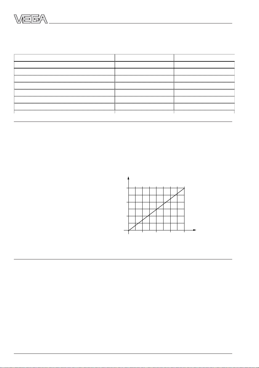
Max. permissible load see load diagram:
load in Ω
900
≤ 1 V
SS
600
300
supply voltage
12
18 24 30 36
in V
Measuring accuracy (according to DIN 16 086, DIN V 19 259-1 and IEC 770)
Measuring deviation
Reference conditions acc. to IEC 770, e.g.
- temperature 15°C … 35°C
- rel. humidity 45 % … 75 %
- air pressure 860 mbar … 1060 mbar
Determination of characteristics limit point adjustment acc. to DIN 16 086
Characteristics linear
Deviation in characteristics
Hysteresis (repeatability)
1)
Relating to the nominal range
2)
In compensated temperature range of 0°C … +80°C, reference temperature 20°C
3)
According to IEC 770, Punkt 6.3.2 related to the nominal range
4)
The use of a properly fitting cable seal in the cable connection is necessary for maintaining the housing
protection IP 66. If the seal used does not fit the cable, it should be replaced by a suitable one.
5)
FDA approved
4 Pressure transmitter D98
1)
1)
< 0.25 %
< 0.02 %
Page 5

Technical data
Influence of the ambient temperature
Average temperature coefficient
of the zero signal
1) 2)
< 0.15 %/10 K
Long-term stability
Long-term stability of the zero signal
1) 3)
< 0.1 %/2 years
Other actuating variables
Vibration resistance mechanical vibration with 4 g and
5 … 100 Hz, tested acc. to the regulations of
German Lloyd, GL-characteristics 2
Ambient conditions
Temperatures
Ambient temperature -40°C … +85°C
Storage and transport temperature -50°C … +85°C
Product temperature -40°C … +100°C (1 h up to +140°C)
Protective measures
Protection class IP 66 (EN 60 529)
Connection cable
Cable entry M20x1.5 (for cable ø 5…9 mm)
Screw terminals for conductor cross-sections of up to 2.5 mm
Materials, wetted parts
Process connection stainless steel 1.4435
Diaphragm sapphire-ceramic® (99.9 % Oxide-ceramic)
Seal, measuring cell
Materials, non-wetted parts
Housing stainless steel 1.4571
Ground terminal stainless steel 1.4305
4)
5)
EPDM
2
Weight
Weight 1.4 kg … 1.6 kg
CE conformity
The pressure transmitter D98 meets the requirements of EMC (89/336/EC) and NSR (73/23/
EWG). Conformity has been judged according to the following standards:
EMC emission EN 50 081 - 1: 1992
susceptibility EN 50 082 - 2: 1995
NSR EN 61 010: 1993
Pressure transmitter D98 5
Page 6

2.3 Dimensions
D98 DN 25 D98 DN 50
Technical data
188
164
200
176
TA
TB
6 Pressure transmitter D98
Page 7

Mounting
3 Mounting
3.1 Mounting instructions
Cable entry
The pressure transmitter can be mounted in
any position.
Cable entries must point downward to avoid
moisture ingress. For this purpose, the housing can be rotated by 330 °. With vertically
mounted sensors, the connection cable to the
housing must point downward so that rain
and condensed water can drip off. This applies especially to outdoor mounting, or
mounting in humid rooms (e.g. caused by
cleaning processes) or on cooled or heated
vessels.
3.2 Compensation of the atmospheric pressure
The atmospheric pressure is compensated
via a breather facility integrated in the housing (air-permeable and moisture-resistant
PTFE insert).
Moisture
Pressure transmitter D98 7
Page 8

4 Electrical connection
Electrical connection
4.1 Connection instructions
The electronics in the pressure transmitter
requires a supply voltage of 12 … 36 V DC.
The electronics is designed in two-wire technology i.e. supply voltage (DC) and measuring signal are led via the same two-wire
connection cable to the terminals. The supply
voltage is provided by an external power
supply unit.
Please note that the external power supply
according to DIN VDE 0106, part 101 must
be reliably separated from the mains circuits.
Note the following instructions for electrical
connection:
- Connection must be made according to
country-specific installation standards (e.g.
in Germany acc. to the VDE regulations).
- The terminal voltage should not exceed 36
V to avoid damage to the electronics.
- The electrical connection is provided with
polarity reversal.
- The wiring between pressure transmitter
and power supply can be carried out with
standard two-core cable.
- Screened cable is recommended in case
of strong electromagnetic interference.
Install the screening on one side of the
sensor.
- In case of overvoltage, we recommend
using a pressure transmitter with integrated overvoltage protection or installing
VEGA overvoltage arresters.
- A seal must be used which correctly fits
the cable in the cable entry.
Connection cable
Please make sure that the connection cables
are specified for the anticipated operating
temperatures in your plant. The cable must
have an outer diameter of 5 ... 9 mm, otherwise the sealing effect of the cable entry
cannot be guaranteed.
8 Pressure transmitter D98
Page 9

Electrical connection
4.2 Terminal assignment
4-20mA
1 2 3 4 5
-
+
4...20mA
12...36 V DC
+
control unit 4 … 20 mA
-
-
energy supply
+
12 … 36 V DC
4.3 Connection example
The following examples are valid for a direct connection to the terminals of the pressure transmitter. When the external connection housing is used, the connections are made to the appropriate terminals of the housing.
The hydrostatic pressure transmitter D98 is adjusted to the indicated measuring range by
VEGA and has no adjustment option.
Oscillator is supplied by a power supply unit
The adjustment is made via the indicating instrument.
Ammeter for on-site
control
+ – –
1 2 3
connection terminals
pressure transmitter
U
K
analogue / digital indicating
instrument
U
A
4 … 20 mA
U
H
power supply unit
–
~
+
Oscillator is supplied by a PLC with active input circuit
Evaluation is carried out via PLC.
Ammeter for on-site check
+ – –
1 2 3
connection terminals
pressure transmitter
U
K
4 … 20 mA
memory programmable control
U
–
H
+
Notes:
An ammeter for on-site check of the output current can be connected to the terminals 1 and 3.
This measurement can be carried out during operation without interruption of the mains supply.
Pressure transmitter D98 9
Page 10

5 Diagnostics
Diagnostics
Maintenance
When properly used, pressure transmitters
D98 are maintenance-free.
Should a dismounting of the pressure transmitter be necessary (e.g. vessel cleaning)
we recommend the use of a new seal. You
should only use VEGA seals.
Troubleshooting
If faults do occur, the following measures
must be taken before dismounting the
pressure transmitter:
- check the atmospheric pressure compensation (only with gauge measuring ranges)
- check the electrical connections.
Check the atmospheric pressure compensation
Open the cover of the housing. The measured value must not change. However, if the
displayed value changes, compensation of
the atmospheric pressure is not ensured,
which can result in distortion of the measured
value. Make sure the breather unit is unobstructed. It consists of a black plastic
threaded insert with integrated filter element.
Check the electrical connections
Terminals
Pressure
transmitter
1 2 3
mA
current
voltage
V
current
mA
external
energy
–
+
~
Check the voltage
- The terminal voltage on the pressure
transmitter must be at least 12 V DC.
Check the current
• Initial current with unimmersed diaphragm
of pressure transmitter: approx. 4 mA
• operating measuring current: 4 … 20 mA
• Exceeding or falling short of the specified
measuring range: 20.5 mA and 3.8 mA
• Pressure transmitter damaged or shortcircuited: current > 22 mA or < 3.6 mA
Note:
The pressure acting on the breather must be
the same as the atmospheric pressure in the
open vessel.
10 Pressure transmitter D98
Page 11

Instrument modification
6 Instrument modification
6.1 Exchange of hygienic form seal
In the hygienic connections of pressure
transmitter D98, the ceramic measuring cell is
gaplessly sealed with a radial, form seal.
This form seal (material EPDM-FDA) can be
exchanged by the user without a fresh adjustment being necessary. The criteria and
the time intervals for such an exchange of the
seal are generally defined by the process
and hygienic requirements.
Important:
Use only original replacement seals from
VEGA, article no. 2.17 775!
Please note the following exchange procedure.
Removal procedure:
1 Pressure transmitter should be
unpressurized (switch off process pressure or empty vessel)
2 Loosen the hexagon pressure screw (4)
(width across flats, 46 mm) by turning to
the left.
Note!
The process connection (6) (e.g. compression nut) must not be loosened!
Installation procedure:
1 Place the new form seal (5) over the meas-
uring cell (the conical side must mate with
the process connection).
2 Turning it lightly clockwise, insert the pres-
sure transmitter carefully into the process
connection.
3 Tighten hexagon pressure screw (4) (width
across flats, 46 mm) (45 Nm).
4 Turn the housing (1) of the pressure trans-
mitter to the original position.
The exchange of the form seal is now finished; the removed seal must be properly
disposed of.
1
2
3
4
3 Turn the adapter (3) below the pressure
transmitter housing with a spanner (with
across flats, 36 mm) slightly to the left
(loosen the seal).
5
4 Hold onto the housing (1), pull the entire
pressure transmitter out of the process
connection by carefully turning to the left.
5 Slightly lift the form seal (5) and loosen it
from the ceramic measuring cell.
6 If the form seal (5) does not completely
encircle the measuring cell, the remaining
part must be carefully removed from the
process connection.
Pressure transmitter D98 11
1 Pressure transmitter
2 Headless screw (avoids overwinding and must not be
removed)
3 Adapter
4 Hexagon screw
5 Form seal
6 Process connection
6
Page 12

VEGA Grieshaber KG
Am Hohenstein 113
D-77761 Schiltach
Phone (07836) 50-0
Fax (07836) 50-201
E-Mail info@de.vega.com
www.vega.com
ISO 9001
All statements concerning scope of delivery, application, use and
operating conditions correspond to the information available at the
time of printing.
Technical data subject to alterations
24336 -EN-021030
 Loading...