

Page 1

Operating Instructions
Level and Pressure
Hydrostatic pressure transmitters
PROF I
D96/D97 (Profibus PA)
0 - 20 bar
PROCESS FIELD BUS
BUS
p
Page 2

Safety information, note Ex area
Safety information
Please read this manual carefully, and also take
note of country-specific installation standards
(e.g. the VDE regulations in Germany) as well
as all prevailing safety regulations and accident prevention rules.
For safety and warranty reasons, any internal
work on the instruments, apart from that involved in normal installation and electrical connection, must be carried out only by qualified
VEGA personnel.
2 Pressure transmitter D96/D97 (Profibus PA)
Note Ex area
Please note the attached safety instructions
containing important information on installation
and operation in Ex areas.
These safety instructions are part of the
operating instructions and come with the Ex
approved instruments.
Page 3

Contents
Contents
Safety information ........................................................................ 2
Note Ex area ................................................................................ 2
1 Product description
1.1 Function and configuration .................................................. 4
1.2 Types and versions ............................................................. 5
1.3 Technical data ....................................................................... 6
1.4 Approvals and certificates .................................................. 9
1.5 Dimensions ......................................................................... 10
2 Mounting
2.1 Mounting instructions ......................................................... 12
2.2 Compensation of the atmospheric pressure ................... 12
3 Electrical connection
3.1 Connection instructions ..................................................... 13
3.2 Wiring plan .......................................................................... 14
4 Setup
4.1 Setting the Profibus PA address ...................................... 15
4.2 Setup with module
"Menu-driven adjustment with additional functions" ........ 17
4.3 Setup with adjustment software
VEGA Visual Operating (VVO) ......................................... 23
5 Diagnostics
5.1 Maintenance ....................................................................... 31
5.2 Failure rectification ............................................................. 31
6 Instrument modification
6.1 Exchange of adjustment modules
in the processing unit ........................................................ 32
Pressure transmitter D96/D97 (Profibus PA) 3
Page 4
1 Product description
0 - 20 bar
Product description
1.1 Function and configuration
D96 and D97 pressure transmitters are efficient instruments for hydrostatic level measurement. A dry ceramic-capacitive CERTEC
measuring cell is used as the pressure sensor element for D96. D97 uses a dry metalliccapacitive measuring cell with Duratherm 600
diaphragm. The hydrostatic pressure effects
a capacitance change on the diaphragm.
This capacitance change is detected by an
ASIC (Application Specific Integrated Circuit)
and converted into a pressure-proportional
signal by the integrated electronic module
with microcontroller. Precise, high-resolution
digital processing of measurement data
ensures excellent technical data.
The electronics module is powered by a
Profibus DP - PA segment coupler. The
measured pressure is transmitted as a digital
signal via the bus cable to the processing
system and can be displayed on the indicating module.
To improve reliability, the functionality of important electronic components is continuously checked, and internal parameters such
as sensor value, temperature and operating
voltage are closely monitored.
The pressure transmitters D96 with ceramic
CERTEC® measuring cell offer the advantage
of continuous self-monitoring: the measuring
and reference capacitances of the measuring
cell constitute a predefined ratio over the
entire measuring range. Any deviation from
these data is a reliable indicator of a malfunction of the measuring cell. If errors or malfunctions are detected during these routines,
fault signals are triggered according to the
Profibus PA specification.
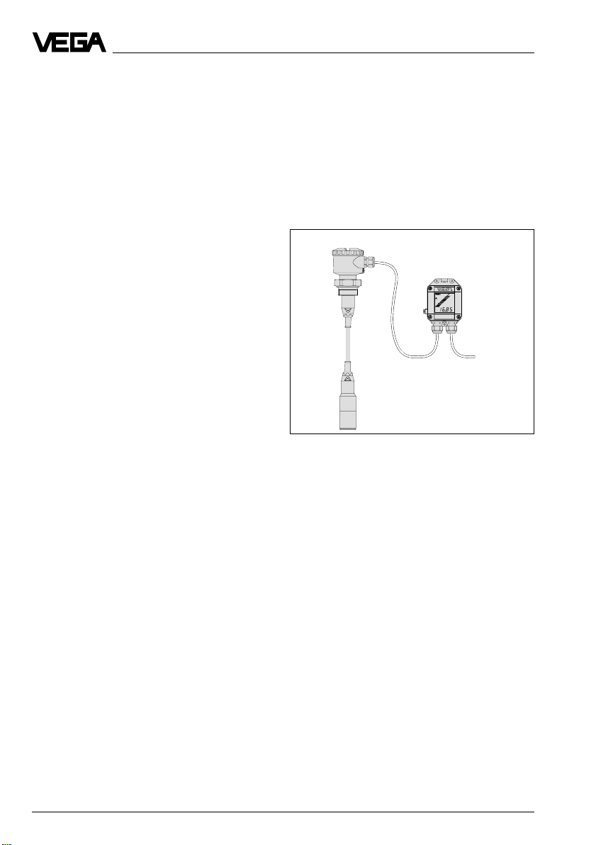
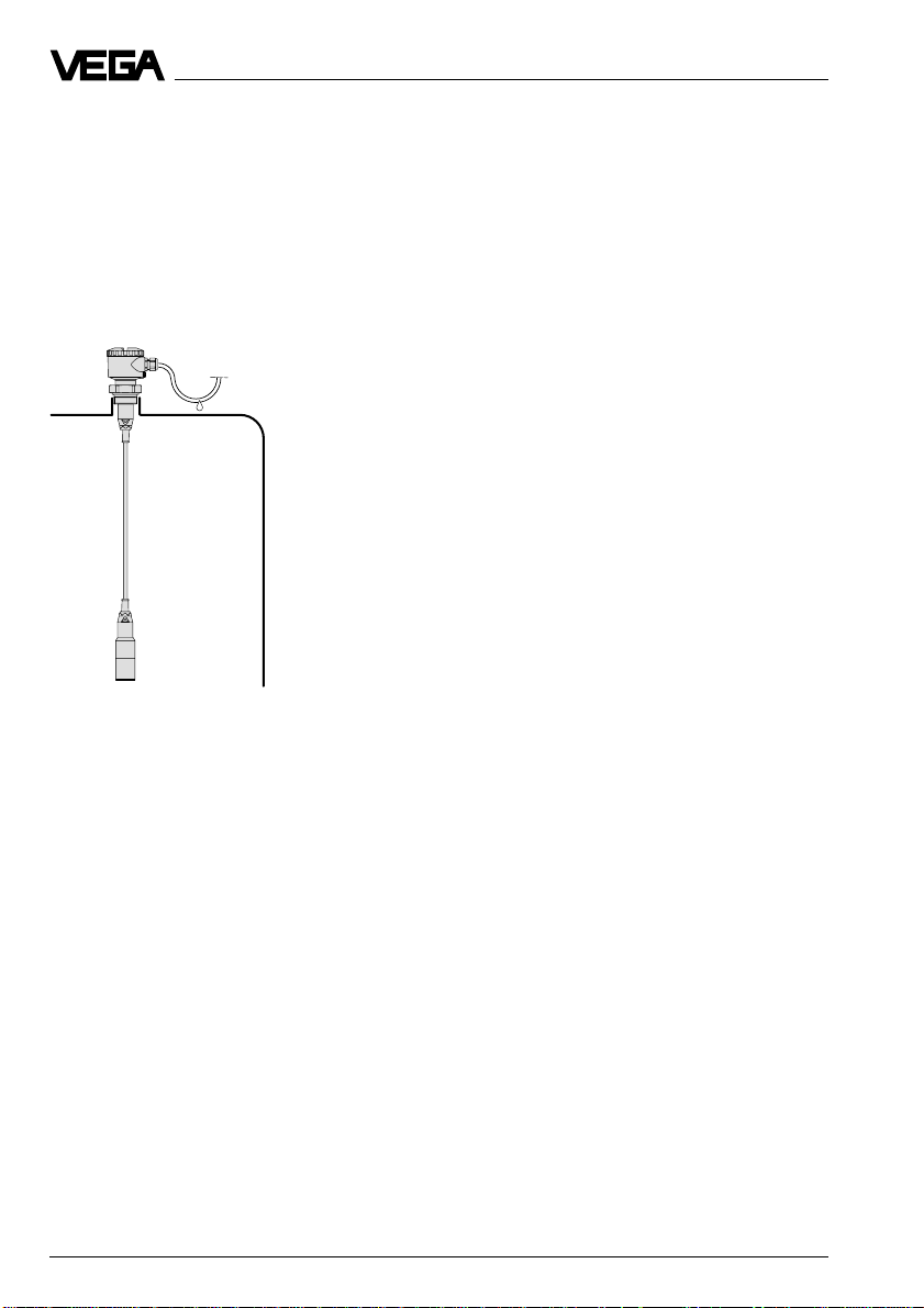
The pressure transmitter consists of two
parts, the transmitter and the processing
unit. Both parts are connected via a threewire screened cable (depending on the ver-
®
sion, with or without breather capillaries). The
processing unit contains the adjustment
elements (address switch, keys and LCD)
and the terminals for the Profibus PA cable.
Transmitter
Processing unit
Profibus PA version
The instrument profile of the pressure transmitter D96/D97 is according to the profile
specification version 3.0. The instrument
master file (GSD) is supplied with the pressure transmitter D96/D97. In addition, the
GSD is available as a download file from the
VEGA homepage (www.vega.com).
Adjustment and indication
The following adjustment versions are available:
- menu-driven adjustment (4 keys and DOTMatrix) in the processing unit
- via PC with the adjustment software VEGA
Visual Operating (VVO)
- optional, processing unit equipped with an
indicating module.
Profibus PA
cable
4 Pressure transmitter D96/D97 (Profibus PA)
Page 5
Product description
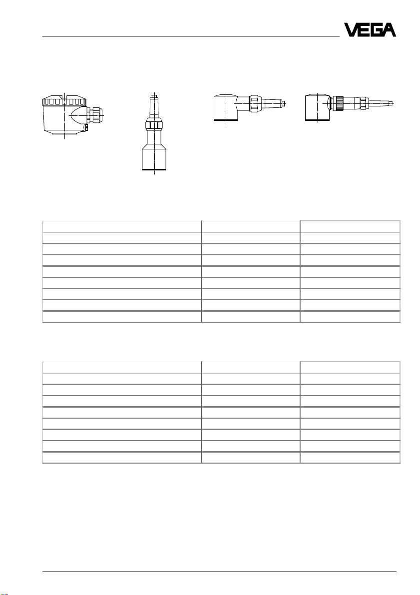
1.2 Types and versions
Housing with
terminals
Measuring ranges D96
Nominal meas. range (gauge pressure) Gauge press. resistance Low pressure resistance
0…0.1 bar / 0…10 kPa 15 bar / 1 500 kPa -0.2 bar / -20 kPa
0…0.2 bar / 0…20 kPa 20 bar / 2 000 kPa -0.4 bar / -40 kPa
0…0.4 bar / 0…40 kPa 30 bar / 3 000 kPa -0.8 bar / -80 kPa
0…1.0 bar / 0…100 kPa 35 bar / 3 500 kPa -1.0 bar / -100 kPa
0…2.5 bar / 0…250 kPa 50 bar / 5 000 kPa -1.0 bar / -100 kPa
0…5.0 bar / 0…500 kPa 65 bar / 6 500 kPa -1.0 bar / -100 kPa
0…10.0 bar / 0…1 000 kPa 90 bar / 9 000 kPa -1.0 bar / -100 kPa
0…20.0 bar / 0…2 000 kPa 130 bar / 13 000 kPa -1.0 bar / -100 kPa
Cable outlet
axial
Cable outlet lateral Plug connection
lateral
Measuring ranges D97
Nominal meas. range (gauge pressure) Gauge press. resistance Low pressure resistance
0…0.1 bar / 0…10 kPa 2.5 bar / 250 kPa -0.1 bar / -10 kPa
0…0.2 bar / 0…20 kPa 5 bar / 500 kP a -0.2 bar / -20 kPa
0…0.4 bar / 0…40 kPa 10 bar / 1 000 kPa -0.4 bar / -40 kPa
0…1.0 bar / 0…100 kPa 25 bar / 2 500 kPa -1.0 bar / -100 kPa
0…2.5 bar / 0…250 kPa 25 bar / 2 500 kPa -1.0 bar / -100 kPa
0…5.0 bar / 0…500 kPa 25 bar / 2 500 kPa -1.0 bar / -100 kPa
0…10.0 bar / 0…1 000 kPa 25 bar / 2 500 kPa -1.0 bar / -100 kPa
0…20.0 bar / 0…2 000 kPa 25 bar / 2 500 kPa -1.0 bar / -100 kPa
Pressure transmitter D96/D97 (Profibus PA) 5
Page 6

Product description
1.3 Technical data
Mechanical data
Transmitter materials, wetted parts
Pressure transmitter D96
- transmitter stainless steel 1.4571
- diaphragm sapphire-ceramic® (99.9 % Oxide-ceramic)
- suspension cable PE
cable bushing CSM
- suspension hose FEP
- connection tube stainless steel 1.4571
- mounting boss stainless steel 1.4571
- transmitter protection PE plastic coating with funnel
- seal measuring cell Viton, Kalrez, EPDM, Hifluor
Pressure transmitter D97
- transmitter stainless steel 1.4571
- diaphragm Duratherm 600
- suspension cable PE
cable bushing CSM
- suspension hose FEP
- connection tube stainless steel 1.4571
- mounting boss stainless steel 1.4571
- transmitter protection PE plastic coating with funnel
Transmitter materials, non-wetted parts
Transmitter housing - Alu die casting, powder-coated
Straining clamp galvanized steel
Closing screw stainless steel 1.4305
- stainless steel 1.4571
Material of the processing unit
Housing high resistance plastic PBT (Polyester)
Ground terminal stainless steel 1.4305
Window of the indication module Lexan
Adjustment and indicating elements (in the processing unit)
Menu-driven adjustment with
additional functions
- adjustment elements 4 keys
- indicating elements DOT-matrix display, 3 lines with 7 digits each
Version without adjustment module
- adjustment element 8-pole mini coding switch for adjustment of the
Indication module LC-display with
6 Pressure transmitter D96/D97 (Profibus PA)
bus address
- bar graph (20 segments)
- digital value (4 digits)
- tendency indicators for rising or falling values
Page 7

Product description
Weight
Basic weight approx. 1.5 kg
Suspension cable approx. 0.12 kg/m
Closing screw approx. 0.4 kg
Straining clamp approx. 0.2 kg
Sensor with terminal housing or
with direct cable outlet approx. 2.2 kg
Processing unit approx. 480 g
Electrical data
Adjustment ranges
Zero adjustable from -20 … +95 % of nominal range
Span adjustable from 3.3 … 120 % of nominal range
Supply and signal circuit
Supply voltage 9 … 32 V DC
(delivered by the segment coupler)
Current consumption 10 mA ± 1 mA
Integration time 0 … 50 s
Rise time 70 ms (ti = 0 sec; 0 – 63 %)
Connection cable, processing unit – Profibus PA
Cable entry M20 x 1.5 (for cable ø 5 … 9 mm)
Screw terminals for conductor cross-sections of up to 2.5 mm
Recommended bus cable types - SINEC 6XV 830-5AH10 (Siemens AG)
- SINEC L2 6XV1 830-35H10 (Siemens AG)
- 3079 A (Belden)
2
Connection cable, processing unit – Transmitter
Cable entry M20 x 1.5 (for cable ø 5 … 9 mm)
Screw terminals for conductor cross-sections of up to 2.5 mm
2
Transmitter
- with fixed cable outlet 3-wire screened, with breather capillaries
- with cable connection terminals 3-wire screened
Protective measures
1)
Protection
- transmitter with fixed cable outlet IP 68
- transmitter with terminal housing IP 66/IP 67
- processing unit IP 66/IP 67
Protection class III
Overvoltage category III
1)
The use of a properly fitting cable seal in the cable connection is necessary for maintaining the housing
protection. If the seal used does not fit the cable, it should be replaced by a suitable one.
Pressure transmitter D96/D97 (Profibus PA) 7
Page 8

Product description
Accuracy (similar to DIN 16 086, DIN V 19 259 - 1 and IEC 770)
Deviation
Reference conditions (acc. to IEC 770)
- temperature 15°C … 35°C
- rel. humidity 45 % … 75 %
- air pressure 860 mbar … 1060 mbar/86 kPa … 106 kPa
Determination of characteristics limit point adjustment acc. to DIN 16 086
Characteristics linear
Deviation in characteristics
- Turn Down 1 : 1 < 0.25 % with accuracy class 0.25
- Turn Down up to 1 : 5 typ. < 0.3 % with accuracy class 0.25
- Turn Down up to 1 : 10 typ. < 0.4 % with accuracy class 0.25
Hysteresis 1) and repeatability
- D96 (ceramic measuring cell) < 0.02 %
- D97 (metal measuring cell) < 0.05 %
Influence of the ambient temperature
Average temperature coefficient
of the zero signal
1) 2)
- Turn Down 1 : 1 < 0.15 %/10 K with accuracy class 0.25
- Turn Down up to 1 : 5 typ. < 0.225 %/10 K with accuracy class 0.25
- Turn Down up to 1 : 10 typ. < 0.3 %/10 K with accuracy class 0.25
1)
< 0.1 % with accuracy class 0.1
typ. < 0.1 % with accuracy class 0.1
1)
typ. < 0.2 % with accuracy class 0.1
< 0.05 %/10 K with accuracy class 0.1
typ. < 0.075 %/10 K with accuracy class 0.1
typ. < 0.1 %/10 K with accuracy class 0.1
Long-term stability
Long-term drift of the zero signal
3)
- D96 (ceramic measuring cell) < 0.1 % per 2 years
- D97 (metal measuring cell) < 0.1 % per 2 years
Other actuating variables
Calibration position upright, diaphragm points downwards
Influence of the installation position
- D96 (ceramic measuring cell) < 0.2 mbar
- D97 (metallic measuring cell) < 5.0 mbar
Vibration resistance mechanical vibrations with 4 g and
5 … 100 Hz, tested acc. to the regulations of
German Lloyd GL-characteristics 2
1)
Relating to the nominal range.
2)
In compensated temperature range of 0°C … +80°C, reference temperature 20°C.
3)
Acc. to IEC 770, item 6.1.2 relating to the nominal range.
8 Pressure transmitter D96/D97 (Profibus PA)
Page 9

Product description
Operating conditions
Ambient conditions
Ambient temperature -40°C … +85°C
- with indicating module -20°C … +70°C
Storage and transport temperature -40°C … +85°C
Pressure transmitter D96
Product temperature
with Viton seal
tube version -20°C … +85°C
FEP suspension hose -20°C … +85°C
PE cable -20°C … +60°C
with EPDM seal
tube version -40°C … +85°C
FEP suspension hose -40°C … +85°C
PE cable -40°C … +60°C
with Hilfuor seal
tube version -10°C … +85°C
FEP suspension hose -10°C … +85°C
PE cable -10°C … +60°C
with Kalrez seal
tube version 0°C … +85°C
FEP suspension hose 0°C … +85°C
PE cable 0°C … +60°C
Pressure transmitter D97
Product temperature
tube version -40°C … +85°C
FEP suspension hose -40°C … +85°C
PE cable -40°C … +60°C
1.4 Approvals and certificates
Approvals
- Ex Zone 2
- CENELEC EEx ia IIC
- ATEX II 1G EEx ia IIC
If the use of approved instruments is required for certain applications, the appropriate
official documents (test reports, test certificates and conformity certificates) must be observed. These are supplied with the respective instrument.
CE conformity
D96 and D97 pressure transmitters meet the requirements of EMC (89/336/EWG) and NSR
(73/23/EWG). Conformity has been judged acc. to the following standards:
EMC Emission EN 50 081 - 1: 1992
NSR EN 61 010 - 1: 1993
NAMUR regulations
Full compliance with the NAMUR regulations NE 21, May 1993.
Pressure transmitter D96/D97 (Profibus PA) 9
Susceptibility EN 50 082 - 2: 1995
Page 10
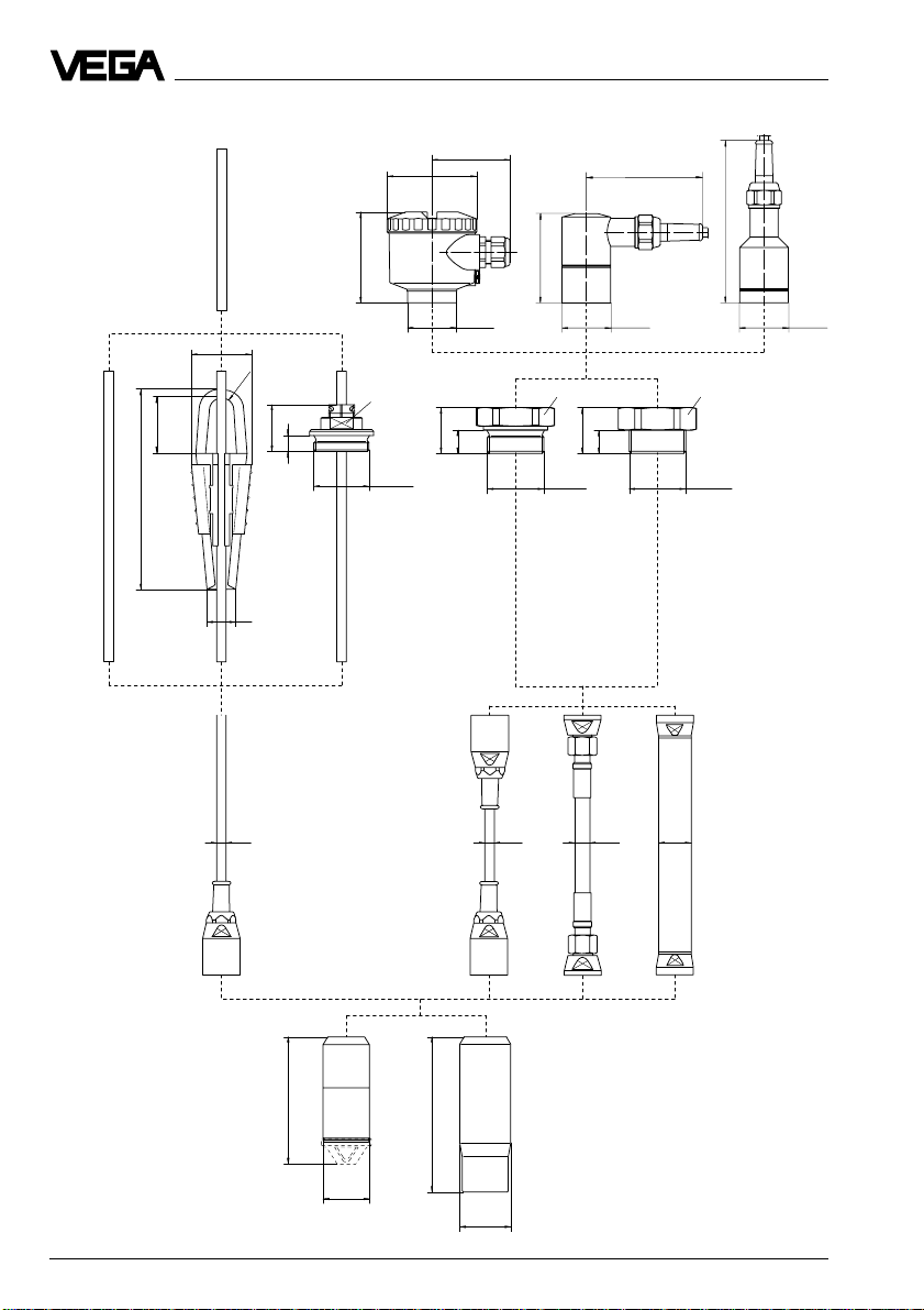
Product description
1.5 Dimensions
175
C1
52
R 11
49
25
X4 A4 V4
A1, A2, B1, B2
66
ø 76
77
ø 41,6
SW 30
41
14
G 1½ A
39
14
C3 D3
100
77
ø 41,6 ø 41,6
SW 60
39
14
G 1½ A
139
SW 60
1½" NPT
G4 N4
ø 10
K
ø 10 ø 13 ø 28
KS R
XP
110
ø 40
134
ø 44
10 Pressure transmitter D96/D97 (Profibus PA)
Page 11
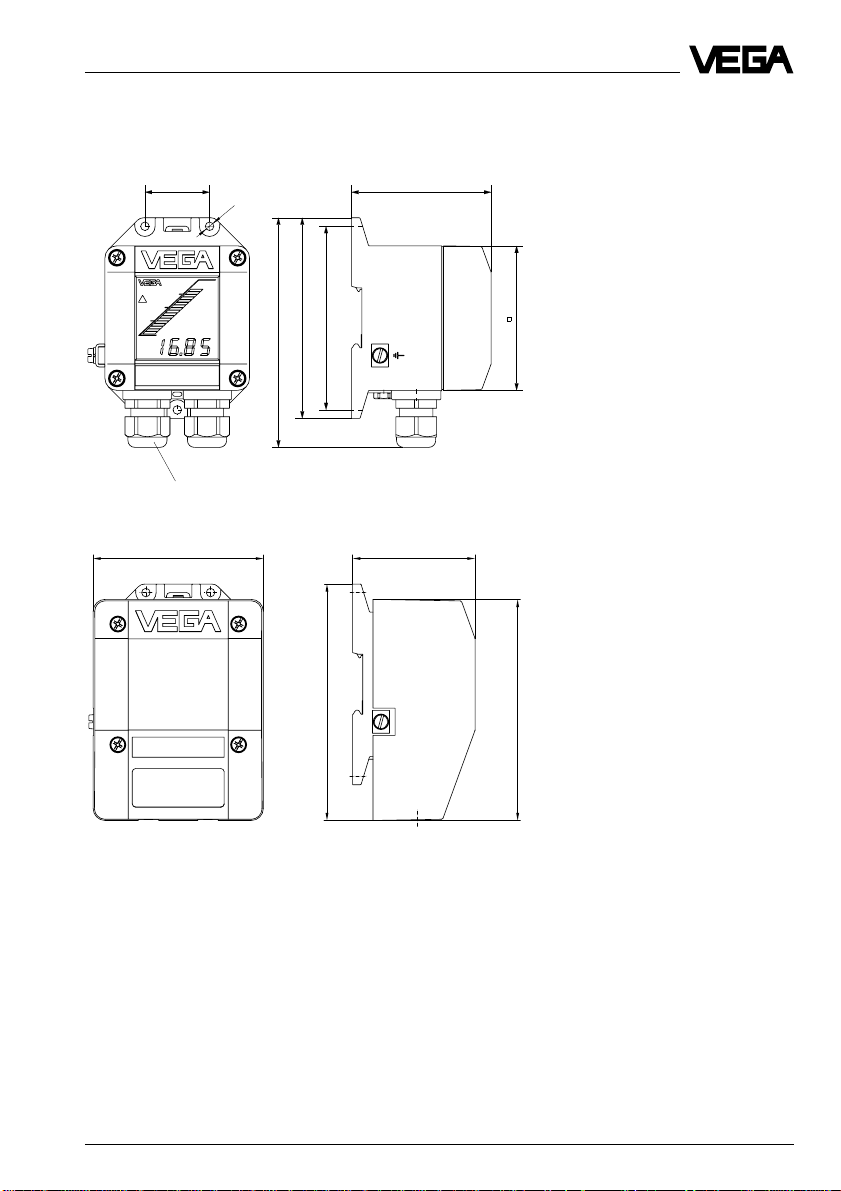
Product description
Processing unit
with display module
38 82
5
˘
M20x1,5
with protective cover
135
118
108
139
85
72100
130
Pressure transmitter D96/D97 (Profibus PA) 11
Page 12
2 Mounting
Mounting
2.1 Mounting instructions
The pressure transmitter can be mounted in
any position. Cable entries must point downwards to avoid moisture ingress. For this
purpose, the housing can be rotated by 330°
in relation to the mounting part.
An appropriate connection seal must be
used for mounting. This seal is either supplied with the pressure transmitter or must be
provided by the customer.
2.2 Compensation of the atmospheric pressure
On instruments for gauge pressure measurement, the atmospheric pressure is compensated via a breather facility integrated in
the housing.
Pressure transmitter with housing
- via an integrated breather facility (PTFE
use 1)), protection IP 66
- via the capillaries of a special cable con-
nected to the terminals, protection IP 67
Pressure transmitter with direct cable
outlet
- via the capillaries of a special cable con-
nected to the terminals, protection IP 68
We recommend leading a special cable to
the processing unit and carrying out the
pressure compensation via the integrated
breather facility there.
Processing unit
Observe the following instructions:
- as a rule, there must be the same atmos-
pheric pressure on the breather facility as
on the vessel
- the pressure compensation must be made
in dry environment
- with vertical wall mounting, cable entries
must point downward to avoid moisture
ingress and buildup on the breather facility.
1)
air permeable and moisture-blocking
12 Pressure transmitter D96/D97 (Profibus PA)
Page 13

Electrical connection
3 Electrical connection
3.1 Connection instructions
The electronics in pressure transmitter D96/
D97 requires a supply voltage of
9 … 32 V DC. The supply voltage and the
digital output signal are led via the same twowire cable to the terminals. The external energy is provided via a segment coupler.
Note the following instructions for electrical
connection:
- Connection must be made according to the
country-specific installation standards (e.g.
in Germany acc. to the VDE regulations).
- The electrical connection must have a protective measure against polarity reversal.
- The connection of field instruments is generally made via T-adapters on stubs.
- Screened cable is recommended for connection (cable types, see chapter "1.3
Technical data"). The shielding must be
grounded on both ends (on the T-adapter
and on the connection housing of D96/97).
- For use in Ex areas, the installation regulations must be observed.
Safety information for Ex applications
As a rule, do all connecting work in the complete absence of line voltage. Always switch
off the power supply before you carry out
connecting work on the sensors. Protect
yourself and the instruments.
Qualified personnel
Instruments used in Ex areas must be installed only by qualified personnel. The qualified personnel must observe and understand
the mounting regulations and the supplied
type approval and conformity certificates.
If an instrument is used in hazardous areas,
the respective regulations, conformity certificates and type approvals of the sensors,
separators or safety barriers must be noted
(e.g. DIN VDE 0165).
Sensors used in Ex areas must be connected only to intrinsically safe circuits. The
permissible electrical values are stated in the
conformity certificate or the type approval
certificate.
Intrinsically safe circuits with more than one
active instrument (instrument delivering electrical energy) are not allowed. Please note the
special installation regulations (DIN VDE
0165).
Certain pressure transmitters are provided
with a warning label informing of measures to
be taken to avoid the danger of electrostatic
discharge. Note the content of the warning
label.
Pressure transmitter D96/D97 (Profibus PA) 13
Page 14

3.2 Wiring plan
Transmitter with direct
cable outlet
Breather capillaries
Suspension cable
br
bl
ge
Screen
Transmitter with terminal
housing
Zum Anschluß an
For connection to
E21 PA
4321543215
TransmitterTransmitter
Klemmeinsatz
terminal
Processing unit
Transmitter
E21PA
bl
br
ge
Electrical connection
Display module
OK
121110231
PA+PA
AM10
-
4
PA +
Profibus PA cable
PA -
14 Pressure transmitter D96/D97 (Profibus PA)
Page 15

Setup
4 Setup
4.1 Setting the Profibus PA address
Since each bus participant must have its own
address by which it is identified on the bus,
the address must be adjusted before setup
of the transmitter. Depending on the instrument version, this is done either with the
module "Menu-driven adjustment" or the
address switch.
Address adjustment with the address
switch
Address
12345678
on
off
The transmitter is delivered with the address
set as shown (all switches position "on").
If the mini coding switch is set to address
126 and higher (factory setting), the address
can be modified via software (with VVO).
However, this is only possible if the transmitter is connected as the only participant with
address 126 on the bus. For this reason, we
recommend adjusting the address of the
sensor via the hardware (switch) before
connecting to the bus.
Example:
To select address 37, set switch 1 (value 1),
switch 3 (value 4) and switch 6 (value 32) to
position "on". Set all other switches to position
"off".
Address
12345678
on
off
1 2 4 8 16 32 64 128
1+4+32=37
S
H
S
H
value
Address adjustment with the module
"Menu-driven adjustment with additional functions"
The Profibus PA transmitter is delivered with
the address set to "126". To modify the address via the keyboard, the transmitter must
be connected to the power supply. This does
not have to be over the bus cable. You can
use a standard power supply unit or a battery (9 … 32 V DC, 10 mA).
OK
121110231
PA+PA
Transmitter
With the arrow key and the "OK" key, you
move to the menu item "Instrument address".
There you can adjust the address (0 … 125)
with the "+" and "–" key. Save the adjusted
address with the "OK" key.
Operate
0.123
bar
Ad-
just-
ment
E21PA
–+
U
B
Calcu-
lation
AM10
-
Output
Station
address
126
Simula-
tion
Addi-
tional
funct.
Escape
Pressure transmitter D96/D97 (Profibus PA) 15
Page 16

Further adjustment steps (adjust PA output,
adjustment etc.) can also be carried out if the
processing unit is connected to a power
supply unit. However, adjustment is also
possible at a later time (when the processing
unit is connected to the bus cable).
Adjustment can be simplified by temporarily
mounting the cover or the display module on
the processing unit laterally or displaced
downwards.
Processing unit
Display module
OK
121110231
PA+PA
Transmitter
AM10
-
E21PA
0 - 20 bar
Setup
Tighten screws lightly
16 Pressure transmitter D96/D97 (Profibus PA)
Page 17

Setup
4.2 Setup with module "Menu-driven adjustment with additional functions"
Adjustment elements
Indication of:
- measured value
- functions in menu
▼ Jump to the menu below
with the "OK" key
▲ Return to menu above with
the "OK" key
Depending on parameter:
change value (increase) or
choose out of a list
+
OPERATE
3.00
mbar
Depending on the parameter: change value (decrease) or choose out of a
list
–>
OK
–
Adjustment with the multifunctional module is
menu-orientated and is made via the four
keys in conjunction with the text display. The
switchover from the measured value indication to the main menu is made with the "OK"
key. Use the "®" key to change within a menu
from one menu item to another.
Branching points
A branching point is shown by the ▼ symbol
and enables a jump to the menu below with
the "OK" key. In this menu you can find parameters which belong together according to
function (possibly in other submenus).
Choose menu item or interrupt
adjustment
Depending on the menu item, save
the adjusted value or change the
menu level
Reset
A reset is indicated by the ▲ symbol and
enables a jump up to the menu above with
the "OK" key.
An automatic jump back to measured value
indication is triggered 60 minutes after the
last key push.
Parameters have no ▲ or ▼ symbol. The
value of the parameters can be modified with
the "+" and "–" keys or chosen from a list.
When these keys are pushed once, the value
flashes first. When pushed again, the value is
modified. The modified value can be saved
with the "OK" key. Push the "®" key to cancel
input (without saving the modification).
Certain parameters can be displayed but not
modified.
Pressure transmitter D96/D97 (Profibus PA) 17
Page 18

Menu schematic
Setup
Operate
0,0
skal
Adjust-
ment
Measured value
indication
Calcu-
lation
Lin.-
curve
activ
with PA
output "Pressure"
Output
PA-
output
Lin%
pressure
is only displayed if a
linearisation curve was
activated with VVO and
the PA output is set to
Lin%
with PA output
"%" or "Lin%"
%
ti
1
s
Scaling
out
0
%=
0
Unit
0,0
skal
mbar
psi
kPa
%
Lin%
inHg
Zurück
100
%=
1000
Escape
Decimal
point
888,8
Unit
0,0
%
mbar
psi
kPa
m
ft
inch
inHg
Simula-
tion
Sim.
x,xx
bar
Escape
Escape
Adjust
with
pres.
Zero
0,0
%
Offset
correc-
tion
Offset
corr.
OK?
Sensor
un-
pres.?
18 Pressure transmitter D96/D97 (Profibus PA)
Escape
Only on pressure transmitter
for relative pressure measurement
Span
100
%
Escape
Adjust
without
pres.
Unit
0,0
bar
psi
kPa
inHg
Escape
on sensors with a measuring range <1 bar
the unit
mbar
Offset
correc-
tion
Offset
corr.
OK?
Sensor
un-
pres.?
is displayed instead of
Zero
0,0
bar
Span
1,000
bar
bar
Escape
Page 19

Setup
Addi-
tional
funct.
Station
address
126
Escape
Sensor
data
Fabr.
date
49.98
Lan-
guage
English
Reset
Escape
Franc.
Ital.
Español
Deutsch
P min
-0,3
bar
1) 1) 1) 1)
1)
The min. and max. values can be set to the actual value
Reset
OK ?
Reset
Now !
OK ?
P max
15,0
bar
Temp.
30,7
°C
T min
23,5
°C
T max
36,2
°C
by pushing the "+" and "–" keys simultaneously.
Diagno-
se no.
- - -
Escape
White letters indicate the parameters
which can be modified with the "+"or "–
" key and saved with the "OK" key.
bar
Sensors or measured value information which cannot be modified in these
positions are in italics..
Lan-
List
These options can be selected with
the "+" or "–" key and saved with the
"OK" key.
Adjust
with
pres.
Escape
Use the arrow key to move to
the right in the menu schematic.
In menu items with these symbols, you can move to the top
or bottom with the "OK" key.
Span
100,0
guage
English
Franc.
Ital.
Español
Deutsch
Pressure transmitter D96/D97 (Profibus PA) 19
Page 20

Setup
Adjust PA output
Operate
0,0
skal
%=
Calcu-
lation
0
0
100
%=
1000
Output
PA-
output
Lin%
pressure
%
Decimal
point
888,8
Scaling
out.
Unit
0,0
%
mbar
psi
kPa
m
ft
inch
inHg
Escape
Escape
Adjust-
ment
The PA output is factory-set to "Lin%". With
this adjustment it is possible to carry out an
adjustment and a volume measurement ( to
measure the volume of a non-linear vessel,
the linearisation curve of the vessel also has
to be programmed into the D96/D97 with the
software VVO). The adjustment "%" enables a
level measurement (also with adjustment). If
only a pressure value should be outputted,
the PA output must be set to "Pressure". An
adjustment is then not possible. Move with
the arrow and "OK" key to the menu item "PA
output", choose there the requested option
with the "+" or "–" key and save with the "OK"
key.
Under "Scaling out." you can modify the
number values (min/max), the position of the
decimal point and the unit (with the "+" or "–"
key the values can be modified, with the "OK"
key the adjustments are saved).
Adjustment
(only possible if "%" or "Lin%" has been chosen for the PA output)
Adjustment taking the current pressure into account (live adjustment)
Live adjustment comprises two steps:
1 Adjustment of zero
2 Adjustment of span
1 Adjustment of zero
(e.g. process pressure zero or vessel
empty)
Set the percentage value to 0.0 %
Zero
0,0
with the "+" or "–" key. Then push the
%
"OK" key.
2 Adjustment of span
(e.g. process pressure zero or vessel level
max.)
Set the percentage value to 100 %
Span
100
with the "+" or "–" key. Then push the
%
"OK" key.
Note:
- A modification of zero does not influence
the adjusted span, i.e. the final value of the
measuring range is shifted.
- Push the "+" and "-" key simultaneously for
standard adjustment of zero/span. The
value jumps directly to 0 %/100 %.
- When pushing the "+" or "–" keys individually, the output signal remains at the last
value; it takes on the adjusted value only
after saving with the "OK" key.
- It is also possible to set values for partial
fillings or partial pressures, e.g. 25 % and
75 %. The pressure transmitter then automatically calculates the values for 0 % or
100 % (only possible with a level difference
>3.3 %).
20 Pressure transmitter D96/D97 (Profibus PA)
Page 21

Setup
Adjustment without taking the current
pressure into account (dry adjustment)
Adjustment without pressure comprises four
steps:
1 Selection of the unit in which the adjustment
is to be carried out
2 Offset correction
3 Adjustment of zero
4 Adjustment of span
The offset correction (only in gauge pressure
mode) defines the reference positions for the
measurement. It can be carried out:
- before or after adjustment of zero and
span
- before or after installation of transmitters.
The transmitter must be unpressurised for
the offset correction!
Adjustment without pressure can be carried
out with the instrument mounted or dismounted (e.g. workroom). Any ambient pressure has no effect on the adjustment.
1 Selection of the unit
Choose the unit with the "+" or "–"
Adjust
without
key. Save the selected unit with
pres.
the "OK" key.
Unit
0,0
mbar
psi
kPa
inHg
2 Adjustment of zero
Adjust zero with the "+" or "–" key
Zero
0,0
and save with the "OK" key.
mbar
4 Adjustment of span
Span
Adjust span with the "+" or "–" key
100,0
and save with the "OK" key.
mbar
Note:
- A modification of zero does not influence
the span.
- By pushing the "+" and "–" keys, the output
remains on the last value - only after saving
with the "OK" key will the output take on the
adjusted value.
Evaluation
Linearisation curve
Lin.-
Is only displayed if a linearisation
curve
curve has been activated with VVO.
activ
Adjustment of the integration time
ti
An integration time ti of 0 s … 50 s
1
can be adjusted with the "+" or "–"
s
shocks. The adjusted value can be saved
with the "OK" key.
Selection of the indicated unit
key for damping of pressure
The measurement unit for the indi-
Unit
0,0
cated measured value as well as
skal
for the display module can be
psi
selected here (with the "+" or "–"
kPa
key and the "OK" key). If you select
%
"scal.", the scaled PA output value
m
ft
will be displayed (as adjusted
inch
under "Scaling outp.").
mbar
Pressure transmitter D96/D97 (Profibus PA) 21
Page 22

Setup
Simulation
Simula-
You can adjust with the "+" or "–"
tion
keys an individual pressure or %
value to check the outputs of the
pressure transmitter and the con-
Sim.
nected components. The adjusted
xx,x
mbar
value flashes during activated simulation. The simulation can be
stopped with the "OK" key.
Additional functions
Sensor data
Important sensor data can be displayed via
the DOT-matrix for information and diagnostic
purposes:
- manufacturing date
- pointer function (p
- pointer function (p
- actual temperature value (Temp)
- pointer function (T
- pointer function (T
- diagnostic number
Additional
funct.
min
max
min
max
)
)
)
)
Language
Lan-
guage
English
Franc.
Ital.
Español
Deutsch
Reset
Reset
Reset
Now?
Reset
Now !
OK ?
The pressure transmitter comes
adjusted to the language in which
it is ordered. The languages German, English, French, Italian or
Spanish can be chosen with the
"+" or "–" key and the "OK" key.
The reset function deletes the adjusted values and resets the parameters to the default values. The
adjustment data again correspond
to the nominal measuring range. The
following data are not reset:
- instrument address
- language
- diagnostics number
- offset correction
- pointer
Station
address
Fabr.
date
49.98
1)
The min. and max. values can be set to the actual
value by pushing the "+" and "–" keys simultaneously.
22 Pressure transmitter D96/D97 (Profibus PA)
xxx
Sensor
data
P min
P max
-0,3
150
mbar
mbar
1)
1) 1) 1)
Temp.
30,7
°C
T min
23,5
°C
T max
36,2
°C
Diagno-
se no.
- - -
Page 23

Setup
4.3 Setup with adjustment software VEGA Visual Operating (VVO)
VVO connection to the bus cable
To operate the sensor with the adjustment
software VVO, you require a Profibus DP
interface card (from Messrs. Softing) in your
PC. This card must be used to provide the
connection between computer and Profibus
DP cable (a connection directly to the sensor
or to the Profibus PA cable is not possible).
The computer with VVO then has the status
"Master, class 2".
Segment
coupler
Profibus PA
cable
VVO
DP cable
Profibus DP
interface card
(Messrs. Softing)
Field distributor
Sensor Sensor Sensor Sensor
If the computer is connected to the Profibus
DP cable, you can start VVO. If the following
presentation is shown on the monitor, you
have to modify the communication settings in
VVO. To do this, click to Configuration, point
to Program and click to Communication.
First click in the window "Communication" to
Profibus DP for PA sensors. Then select the
Profibus card installed in your PC. It is also
possible to modify the settings for baud rate,
further bus parameters and master address.
Note:
Make sure that the master address you are
using is not assigned to another bus participant!
Click to OK, if you are finished with the communication settings. You then have to restart
VVO.
Pressure transmitter D96/D97 (Profibus PA) 23
Page 24

Setup
Sensor configuration
After starting VVO as previously described
or having made connection to the Profibus,
the following presentation will be displayed
on the monitor. Click to Configuration, then
to Measuring system.
If you have already connected several VEGA
sensors to the bus, you can select the sensor to be configured, in this case pressure
transmitter D96/D97. The serial number and
the bus address of the sensors are displayed to enable clear identification.
The menu language of the sensor can be
selected (only relevant for a sensor with
menu-driven adjustment) and the units for the
output of sensor values can be set. If address 126 has been set directly on the sensor, you can assign a bus address to the
sensor in the field "Sensor address". Then
click to Save.
Information about the sensor identification number:
You do not have to modify the adjustment
"VEGA specific No.". Only if you want to make
sure that the pressure transmitter can be
replaced on the Profibus by a sensor of
another manufacturer do you have to choose
the option "Profile specific No.".
Configuration measurement loop
Click to Configuration, point to Measurement loop, then click to Modify.
Now all instruments which are connected to
the bus are shown (identifiable by the bus
address and the serial number). Notice that
in this example, the same serial number appears twice. This is a sensor with a measurement loop for pressure and a second measurement loop for temperature. Choose the
sensor (the measurement loop) with which
you want to create a measurement loop and
click to OK.
24 Pressure transmitter D96/D97 (Profibus PA)
Page 25

Setup
In the window "Modify meas. loop configuration" you can assign a name and a description to the measurement loop. State under
"Application" if you want to create a process
pressure or a level measurement. With OK
you return again to the window "VEGA Visual
Operating". In the following explanations, we
assume that you have chosen the application
"Level measurement". The adjustment "Process pressure measurement" differs only
slightly from the following presentation.
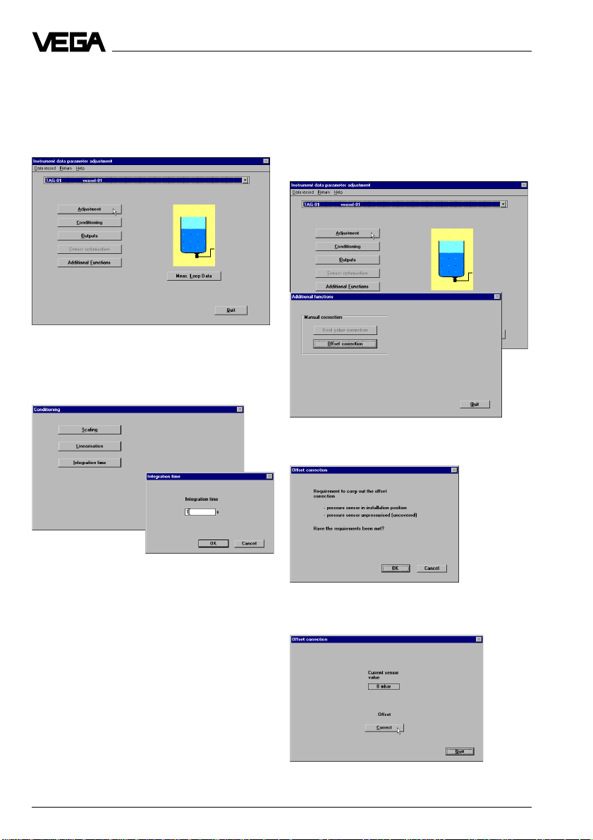
Sensor parameter setting – Adjustment
Click to Instrument data, then to Parameter
adjustment.
From the window "Instrument data parameter
adjustment" you can reach all submenus of
the sensor. To get familiar with the available
options, try out the buttons one after the
other. You will always return to this window. To
carry out the adjustment, click the button
Adjustment.
Click in the window "Adjustment" to Min/Max
adjustment.
Choose the measurement loop in which you
want to make the parameter adjustment and
click to OK.
Pressure transmitter D96/D97 (Profibus PA) 25
Then in the window "Min/Max adjustment" you
have to choose the type of adjustment. If you
want to carry out the "Adjustment without
taking the actual product into account" (dry
adjustment), click to no, then to OK.
Page 26

Setup
Here you can choose in which unit the adjustment should be made (mbar or bar, psi, kPa,
inHg). Then you enter the pressure values
corresponding to 0 % and 100 %. Then click
to OK. The adjustment is now finished.
If you want to carry out the "Adjustment taking the actual product into account" (live
adjustment), click in this window to yes, then
to OK.
Click to Min-Adjustment or to Max-Adjust-
ment to carry out the respective adjustment.
In the window "Min-Adjustment" you choose in
which unit the adjustment should be carried
out (bar, mbar, psi, kPa, inHg). Then click to
Save. The min. adjustment is finished.
In the window "Max-Adjustment" you choose
in which unit the adjustment should be carried out (bar, mbar, psi, kPa, inHg). Then
click to Save. The max. adjustment is finished.
Sensor parameter setting – Linearisation curves
Click in the window "Instrument data parameter adjustment" to Conditioning.
Note:
For min. adjustment and max. adjustment,
defined levels (e.g. 0 % and 100 % or e.g.
20 % and 80 %) have to be present in the
vessel.
26 Pressure transmitter D96/D97 (Profibus PA)
Page 27

Setup
Click in the window "Conditioning" to Lineari-
sation.
In the window "Linearisation" you can choose
the linearisation curves of a cylindrical or a
spherical tank. If you choose a user-programmable curve, you can then click to Edit
and open the program "Tank Calculation".
With this program you can calculate the
curves of different tank shapes (see the
manual "VEGA Visual Operating"). After selection of the curve, click to OK.
Click in the window "Outputs" to Profibus
output.
In the window "Profibus output" you can determine the options for the Profibus output
(acc. to Profibus PA instrument profile). Confirm your adjustments with OK.
Sensor parameter setting – Outputs
Click in the window "Instrument data parameter adjustment" to Outputs.
Pressure transmitter D96/D97 (Profibus PA) 27
Page 28
Setup
Sensor parameter setting – Integration
time
Click in the window "Instrument data parameter adjustment" to Conditioning.
Click in the window "Conditioning" to Integra-
tion time. In the window "Integration time"
you can enter a time interval of max. 50 seconds. Then click to OK.
Sensor parameter setting – Offset correction
Click in the window "Instrument data parameter adjustment" to Additional functions,
then in the window "Additional functions" to
Offset correction.
Confirm the question with OK, in case the
conditions are met.
Click in the window "Offset correction" to
Correct.
28 Pressure transmitter D96/D97 (Profibus PA)
Page 29

Setup
Pointer functions
Click in the window "Instrument data parameter adjustment" to Meas. loop data.
In the window "Meas. loop data", all available,
current sensor values and the peak values
(pointer function) are displayed. With the
button reset you can reset all displayed peak
values to the actual value all at once.
Choose the requested measurement loop
and click to OK.
In the window "Simulation of outputs", you
click to Start to begin the simulation. With the
buttons "<–" and "–>" (or the thumb of the
scroll bar) you can adjust values between 10 % and 110 %. Click to Stop to terminate
the simulation.
Simulation
For checking outputs of the pressure transmitter and connected devices and components, a pressure can be simulated. Click to
Diagnostics, then to Simulation.
Note:
The simulation mode is not terminated automatically, but remains active until you switch it
off!
Pressure transmitter D96/D97 (Profibus PA) 29
Page 30
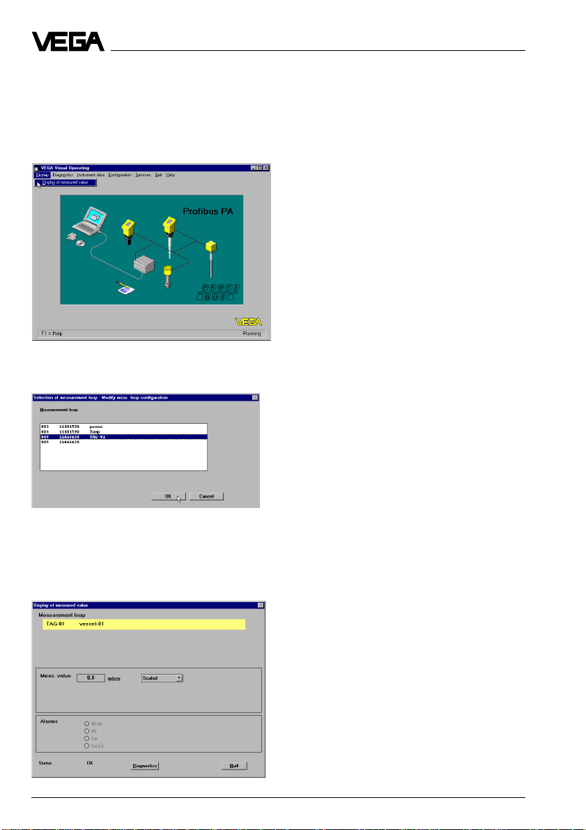
Display of measured values
The current values of the measurement loops
can be displayed from the main menu. Click
to Display and then to "Display of measured
value".
Choose the requested measurement loop
and click to OK.
Setup
In the window "Display of measured value"
you can choose the unit in which the measured value should be displayed. In addition,
you will see the current value. By clicking to
Quit you return to the window "VEGA Visual
Operating".
30 Pressure transmitter D96/D97 (Profibus PA)
Page 31

Diagnostics
5 Diagnostics
5.1 Maintenance
Pressure transmitter D96 and D97 are maintenance-free.
5.2 Failure rectification
Fault signals
The pressure transmitter D96/D97 provides
maximum reliability through its self-test and
continuous self-monitoring. If, however, malfunctions occur, the pressure transmitter
D96/D97 diagnosis distinguishes between
atypical process conditions and faults in the
pressure transmitter D96/D97.
Atypical process conditions
Exceeding or falling short of measuring
range limits (fault signal extinguishes when
the measured value is again in the measuring
range).
Failure in the D96/D97 pressure transmitter
Failure in the electronics, interference or
damage in the measuring cell.
The following table assists in the analysis of
fault signals.
Cause of Fault signal via
failure DOT-matrix Bar graph
Clearly "OPERATE Bar graph 0 %
outside ???? or 100 %
measuring bar" digital value
range flashes
Overload Bar graph 0 %
range or 100 %,
of the digital value
meas. cell four segments
Failure in all segments
D96/D97 flash
Digital indication
flash "- - - -"
On instruments with menu-driven adjustment
with additional functions, the possible causes
are displayed under the menu item "Diagnostics no." in case of failure.
Diagnostics Meaning
no.
1 No frequency from C/D-converter
2 Frequency signal of the capacitor not
within the limit values
3 Frequency signal of the reference
capacitor not within the limit values
4 Frequency signal temperature not
within the limit values
7 Communication with EEPROM dis-
rupted
9 Error in EEPROM CRC-checksum
11 Process connection or electronics
module has been exchanged (appears for approx. 20 s after switching
on for the first time after exchange)
Troubleshooting
If the displayed value does not correspond
to the level in the vessel or to the process
pressure, the following measures must be
taken:
- check the pressure compensation (only
with gauge pressure measuring ranges)
- check the electrical connections.
Checking pressure compensation
Open the processing unit of the pressure
transmitter. The measured value must not
change. However, if the displayed value
changes, compensation of the atmospheric
pressure is not ensured, which can result in
distortion of the measured value. Check the
breather on the processing unit.
Pressure transmitter D96/D97 (Profibus PA) 31
Page 32

6 Instrument modification
Instrument modification
6.1 Exchange of adjustment modules in the processing unit
Display
module
Module for
menu-driven
adjustment
Module without
adjustment
Exchange of the adjustment module
Removal of the adjustment module
• Separate processing unit from the power
supply.
• Remove the screws on the upper side of
the housing and remove the cover or the
display module.
• Disconnect the cables from the terminals,
and if applicable, pull out the plug connection of the display module.
• Remove the two screws of the adjustment
module.
• Remove adjustment module and pull out
plug connection.
Insertion of an adjustment module
• Plug the plug connection of the new adjustment module into the plug-in socket of
the electronics module.
• Fasten the new adjustment module.
• Reconnect the cables, and if applicable,
also the cable from the display module.
• Replace the cover or the display module
of processing unit.
• Reconnect processing unit to power
supply.
Processing unit
The modular construction of the processing
unit allows retrofitting, interchange and removal of the adjustment modules and the
display module. Data previously saved (e.g.
adjustment values) are not stored in the adjustment module but in an EEPROM of the
electronics module and readjustment is
therefore not necessary. The connection of
the modules is made via a 4-pole plug connection.
32 Pressure transmitter D96/D97 (Profibus PA)
Page 33

Notes
Pressure transmitter D96/D97 (Profibus PA) 33
Page 34

Notes
34 Pressure transmitter D96/D97 (Profibus PA)
Page 35

Notes
Pressure transmitter D96/D97 (Profibus PA) 35
Page 36

VEGA Grieshaber KG
Am Hohenstein 113
D-77761 Schiltach
Germany
Phone +49 (0) 7836 50-0
Fax +49 (0) 7836 50-201
E-Mail info@de.vega.com
www.vega.com
ISO 9001
All statements concerning scope of delivery, application, practical
use and operating conditions of the sensors and processing systems correspond to the latest information at the time of printing.
Technical data subject to alteration
2.24 855 / January 2001
 Loading...