

Page 1
Operating Instructions
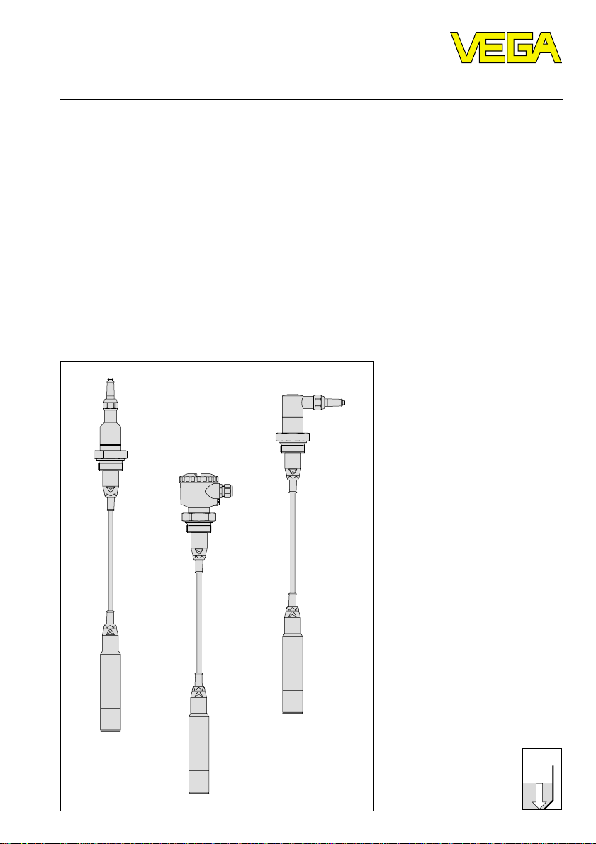
Hydrostatic pressure
transmitters D86/D87
Level and Pressure
p
Page 2

Contents
Safety information ........................................................................ 2
Note Ex area ................................................................................ 2
1 Product description
1.1 Function and configuration .................................................. 4
1.2 Electronics version without adjustment .............................. 5
1.3 Electronics version with integrated adjustment
in connection housing .......................................................... 7
1.4 Electronics for connection to VEGADIS 12 ........................ 8
1.5 Technical data ....................................................................... 9
1.6 Approvals and certificates ................................................ 13
1.7 Dimensions ......................................................................... 14
2 Mounting
2.1 Mounting instructions ......................................................... 16
2.2 Compensation of the atmospheric pressure ................... 16
Contents
Safety information
Please read this manual carefully, and also take
note of country-specific installation standards
(e.g. the VDE regulations in Germany) as well
as all prevailing safety regulations and accident prevention rules.
For safety and warranty reasons, any internal
work on the instruments, apart from that involved in normal installation and electrical connection, must be carried out only by qualified
VEGA personnel.
2 Pressure transmitters D86/D87
Note Ex area
Please note the attached safety instructions
containing important information on installation
and operation in Ex areas.
These safety instructions are part of the
operating instructions and come with the Ex
approved instruments.
Page 3

Contents
3 Electrical connection
3.1 Connection instructions ..................................................... 17
3.2 Terminal assignment .......................................................... 18
3.3 Connection to external connection housing
VEGABOX 01 ..................................................................... 19
3.4 Connection examples ........................................................ 20
4 Setup
4.1 Adjustment structure ......................................................... 21
4.2 Sensor without adjustment ................................................ 22
4.3 Sensor with adjustment insert, adjustment
in the sensor ....................................................................... 22
4.4 Setup with HART® handheld ............................................. 24
5.5 Adjustment with PC directly on the sensor ...................... 30
6 Diagnostics............................................................................... 38
7 Instrument modification
7.1 Retrofitting the adjustment insert ...................................... 39
Pressure transmitters D86/D87 3
Page 4

1 Product description
1.1 Function and configuration
Pressure transmitters D86 and D87 are instruments for hydrostatic level measurement.
Pressure transmitter D86
Measuring cell: dry, ceramic-capacitive
Diaphragm: flush, sapphire-ceramic
Series: suspension version
Standard application: Level and gauge
measurements in water/sewage water,
flumes, basins, deep wells, vessels and
tanks
Pressure transmitter D87
Measuring cell: dry, metallic-capacitive
Diaphragm: Duratherm 600
Series: suspension version
Standard application: Level and gauge
measurements in water/sewage water,
flumes, basins, deep wells, vessels and
tanks
®
Product description
Output signal
The output signal is transferred as a digital or
analogue signal from the pressure transmitter
to the signal conditioning instrument:
• analogue output signal
- unstandardised (in conjunction with
VEGA signal conditioning instrument)
- 4 … 20 mA standardised
• digital output signal (VBUS) for connection
to a digital VEGA signal conditioning instrument (VEGAMET 514V, 515V or VEGALOG
571)
The pressure effects a capacitance change
on the measuring cell. This capacitance
change is detected by an ASIC (Application
Specific Integrated Circuit) and converted
into a pressure-proportional signal by the
integrated electronic module with
microcontroller. Precise, high-resolution digital processing of measurement data ensures
excellent technical data.
To improve reliability, the functionality of important electronic components is continuously checked, and internal parameters such
as sensor value, temperature and operating
voltage are closely monitored.
4 Pressure transmitters D86/D87
Page 5
Product description
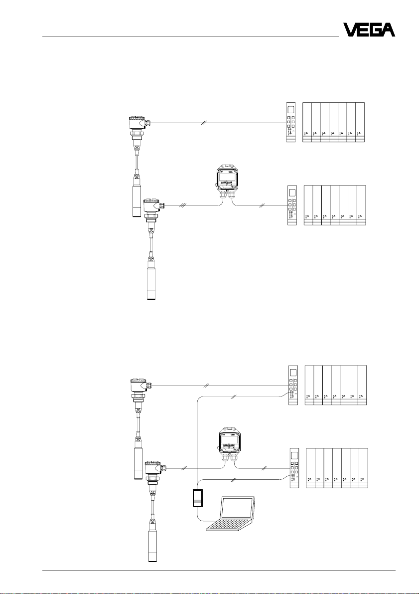
1.2 Electronics version without adjustment
Electronics version A:
Pressure transmitter for connection to VEGA signal conditioning instruments
e.g. IP 66
e.g. IP 67
VEGABOX 01
Zum Anschluss an
For connection to
Druckmessumformer mit
pressure transmitters with
analogem Ausgangssignal
analog output
12310
1112
-
+
-
TRANSMITTER
+
VEGABOX 01
VEGAMET
VEGAMET
VEGALOG
VEGALOG
Electronics version B:
Pressure transmitter for connection to VEGA signal conditioning instruments (digital
transmission VBUS)
VEGAMET
e.g. IP 66
VEGABOX 01
Zum Anschluss an
For connection to
Druckmessumformer mit
pressure transmitters with
analogem Ausgangssignal
analog output
12310
1112
-
+
-
TRANSMITTER
+
VEGABOX 01
VEGAMET
e.g. IP 67
Pressure transmitters D86/D87 5
VEGALOG
VEGALOG
Page 6
Electronics version I:
Pressure transmitter 4 … 20 mA, HART®, VVO
4-20mA
51234
-
+
4...20mA
12V...36V DC
Klemmeinsatz
terminal
Product description
PLC/DCS
250 W
e.g. IP 66
e.g. IP 67
4-20mA
51234
-
+
4...20mA
12V...36V DC
Klemmeinsatz
terminal
HART® handheld
VEGABOX 01
Zum Anschluss an
For connection to
Druckmessumformer mit
pressure transmitters with
analogem Ausgangssignal
analog output
12310
1112
-
+
-
TRANSMITTER
+
VEGABOX 01
PLC/DCS
250 W
VVO
6 Pressure transmitters D86/D87
Page 7

Product description
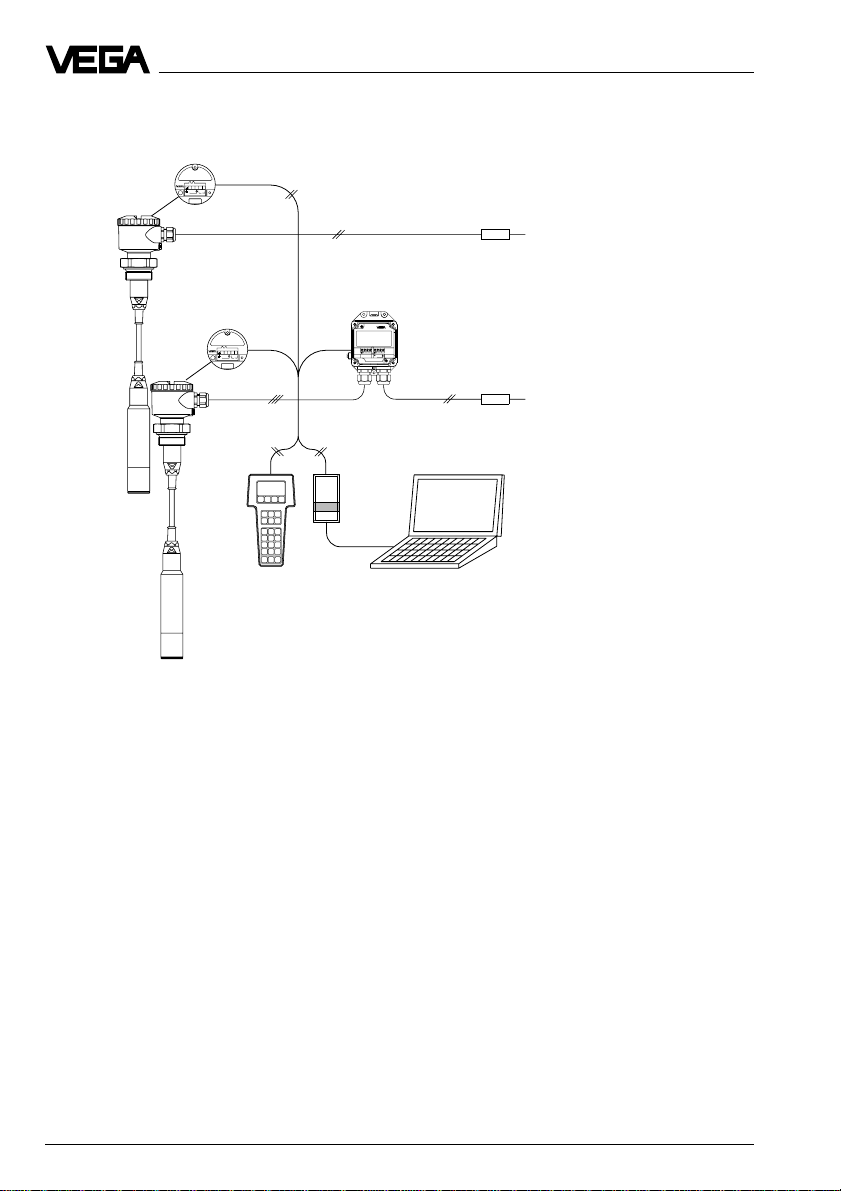
1.3 Electronics version with integrated adjustment in connection housing
Electronics version K:
Pressure transmitter 4 … 20 mA, HART®, VVO adjustable
S
Op
Zt
i
43215
+
-
4...20mA
12V...36V DC
Bedieneinsatz
operating unit
PLC/DCS
250 W
e.g. IP 66
e.g. IP 67
S
Op
Zt
i
43215
+
-
4...20mA
12V...36V DC
Bedieneinsatz
operating unit
HART® handheld
VEGABOX 01
Zum Anschluss an
For connection to
Druckmessumformer mit
pressure transmitters with
analogem Ausgangssignal
analog output
12310
1112
-
+
-
TRANSMITTER
+
VEGABOX 01
PLC/DCS
250 W
VVO
Pressure transmitters D86/D87 7
Page 8

1.4 Electronics for connection to VEGADIS 12
Electronics version L:
Pressure transmitter 4 … 20 mA, HART®, VVO
Zum Anschluß an
For connection to
VEGADIS 12
51234
-
+
12V...36V DC
Klemmeinsatz
terminal
VEGADIS 12
DISPLAYTRANSMITTER
OPERATE
OPERATE
ZERO
ZERO
END
END
POINT
POINT
5876321101112
TRANSMITTER
DISPLAY
+ -
VEGADIS 12
Product description
PLC/
DCS
250 W
e.g. IP 66
e.g. IP 67
Zum Anschluß an
For connection to
VEGADIS 12
51234
-
+
12V...36V DC
Klemmeinsatz
terminal
HART® handheld
VEGADIS 12
DISPLAYTRANSMITTER
OPERATE
OPERATE
ZERO
ZERO
END
END
POINT
POINT
5876321101112
TRANSMITTER
DISPLAY
+ -
VEGADIS 12
VVO
250 W
PLC/
DCS
8 Pressure transmitters D86/D87
Page 9
Product description
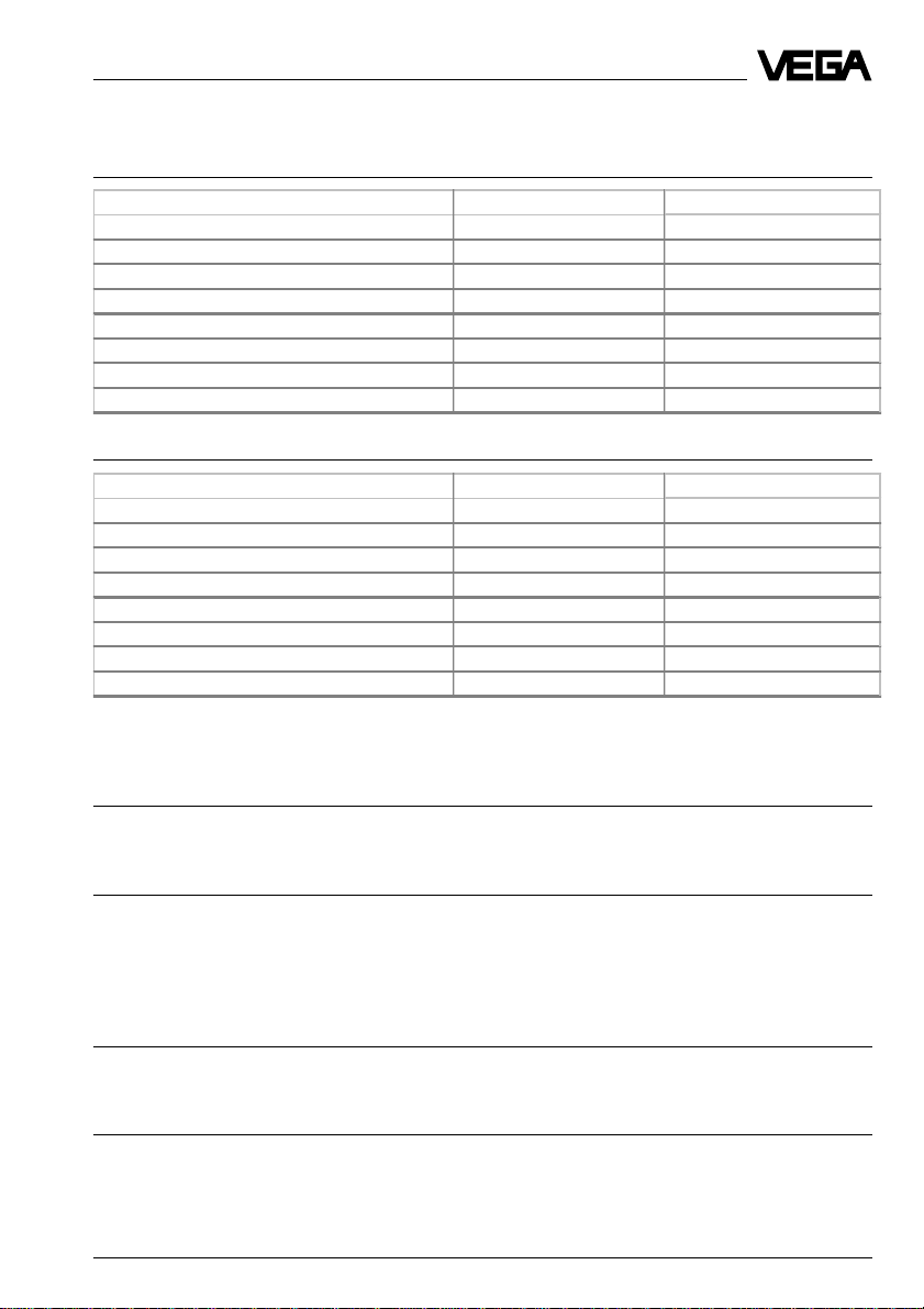
1.5 Technical data
Measuring range Pressure transmitter D86
Nominal measuring range (gauge pr.) Gauge pr. resistance Low pr. resistance
0…0.1 bar / 0…10 kPa 15 bar / 1 500 kPa -0.2 bar / -20 kPa
0…0.2 bar / 0…20 kPa 20 bar / 2 000 kPa -0.4 bar / -40 kPa
0…0.4 bar / 0…40 kPa 30 bar / 3 000 kPa -0.8 bar / -80 kPa
0…1.0 bar / 0…100 kPa 35 bar / 3 500 kPa -1.0 bar / -100 kPa
0…2.5 bar / 0…250 kPa 50 bar / 5 000 kPa -1.0 bar / -100 kPa
0…5.0 bar / 0…500 kPa 65 bar / 6 500 kPa -1.0 bar / -100 kPa
0…10.0 bar / 0…1 000 kPa 90 bar / 9 000 kPa -1.0 bar / -100 kPa
0…20.0 bar / 0…2 000 kPa 130 bar / 13 000 kPa -1.0 bar / -100 kPa
Measuring range Pressure transmitter D87
Nominal measuring range (gauge pr.) Gauge pr. resistance Low pr. resistance
0…0.1 bar / 0…10 kPa 2.5 bar / 250 kPa -0.1 bar / - 10 kPa
0…0.2 bar / 0…20 kPa 5 bar / 500 kPa -0.2 bar / -20 kPa
0…0.4 bar / 0…40 kPa 10 bar / 1 000 kPa -0.4 bar / -40 kPa
0…1.0 bar / 0…100 kPa 25 bar / 2 500 kPa -1.0 bar / -100 kPa
0…2.5 bar / 0…250 kPa 25 bar / 2 500 kPa -1.0 bar / -100 kPa
0…5.0 bar / 0…500 kPa 25 bar / 2 500 kPa -1.0 bar / -100 kPa
0…10.0 bar / 0…1 000 kPa 25 bar / 2 500 kPa -1.0 bar / -100 kPa
0…20.0 bar / 0…2 000 kPa 25 bar / 2 500 kPa -1.0 bar / -100 kPa
Mechanical data
Materials, wetted parts
Process connection stainless steel 1.4571, 1.4435
Diaphragm Duratherm 600
Materials, non-wetted parts
Housing Alu (seawater resistant) PE-powder coated,
External connection housing high resistance plastic PBT (Polyester)
Ground terminal stainless steel 1.4305
Window of the display module safety glass
Weights
Basic weight without housing approx. 1.6 kg
External housing approx. 400 g
Adjustment and display elements
Pressure transmitter
- terminal insert without adjustment elements
- adjustment insert 2 keys, 1 rotary switch
Pressure transmitters D86/D87 9
stainless steel 1.4571
Page 10
Product description
Electrical data
Adjustment ranges
Zero adjustable from -20 … +95 % of nominal range
Span adjustable from 3.3 … 120 % of nominal range
Supply and signal circuit (analogue transmission, 4 … 20 mA),
electronics version A, C, I and K
Supply voltage 12 … 36 V DC
permissible residual ripple USS £ 1 V
- at 100 Hz … 10 kHz USS £ 10 mV
Output signal
- terminal insert - analogue transmission (not standardised)
- adjustment insert 4 … 20 mA (adjustable)
Current limitation approx. 22 mA
Fault signal 22 mA (3.6 mA)
Integration time 0 … 10 s
Rise time 70 ms (ti = 0 sec; 0 … 63 %)
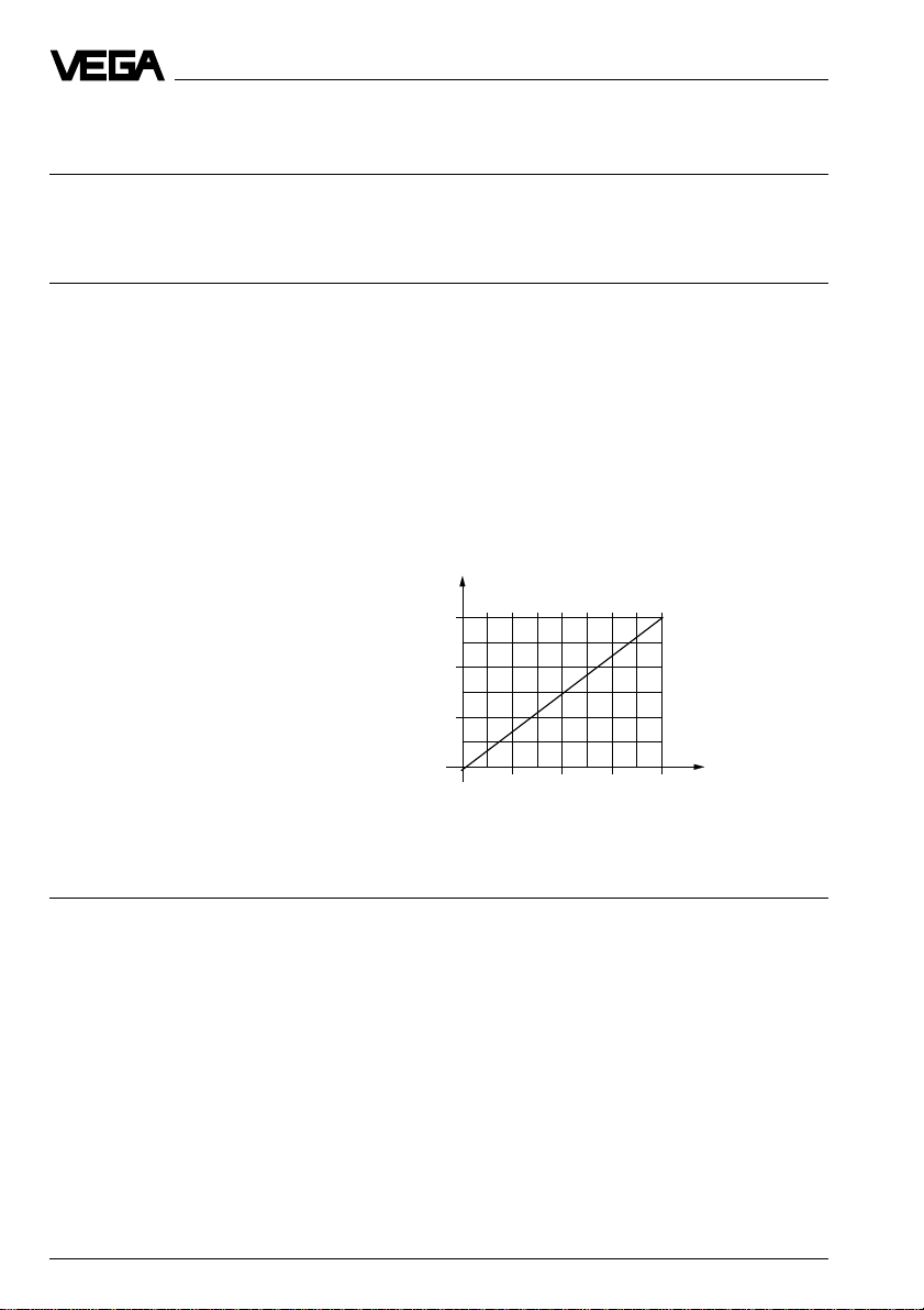
Max. permissible load see load diagram:
-4 … 20 mA
Load in W
900
600
300
Supply voltage
12
18 24 30 36
in V
Supply and signal circuit (analogue transmission, 4 … 20 mA),
additional data for electronics version L
Supply voltage for pressure transmitters
in conjunction with VEGADIS 12
- without display 12 … 36 V DC
- with display 17 … 36 V DC
Max. input current 150 mA
Current signal range 3.5 … 22 mA
Max. permissible load see load diagram:
10 Pressure transmitters D86/D87
Page 11

Product description
Load diagram with display
Load in W
700
500
300
100
18
24 30 36
Supply voltage
in V
Supply and signal circuit on VEGA signal conditioning instruments (digital signal
transmission VBUS), additional data for electronics version B
Supply voltage 25 … 36 V DC, from VEGAMET (VBUS) or
from VEGALOG 571 with EV input card
Data transmission digital (VBUS)
Connection cable 2-wire screened
Cable length max. 1000 m
Integrated overvoltage protection (option)
Nominal response DC voltage
- protective diode 40 V
- gas separator 650 V
Nominal leakage current
- gas separator 20 kA
Connection cables
Cable entry
- housing 2 x M20x1.5 (for cable ø 5…9mm or 9…12mm)
- external connection housing 2 x M20x1.5 (for cable ø 5…9mm or 9…12mm)
Screw terminals
- sensor for wire cross-sections of up to 2.5 mm
- external connection housing for wire cross-sections of up to 2.5 mm
Protective measures
1)
2
2
Protection IP 66, IP 67, IP 68
VEGABOX 01 IP 66 and IP 67
Protection class III
Overvoltage category III
1)
Maintaining the housing protection IP 66 or IP 67 requires the use of a seal that correctly fits the cable in
the cable entry. If the supplied seal does not fit, a suitable seal must be provided by the customer.
Pressure transmitters D86/D87 11
Page 12

Product description
Accuracy (similar to DIN 16 086, DIN V 19 259 - 1 and IEC 770)
Deviation
Reference conditions (acc. to IEC 770)
- temperature 15°C … 30°C
- humidity 45 % … 75 %
- air pressure 86 kPa … 106 kPa
Determination of characteristics limit point adjustment acc. to DIN 16 086
Characteristics linear
Deviation in characteristics incl. hysteresis and repeatability
- Turn Down 1 : 1 < 0.25 % with accuracy class 0.25
- Turn Down up to 1 : 5 typ. < 0.3 % with accuracy class 0.25
- Turn Down up to 1 : 10 typ. < 0.4 % with accuracy class 0.25
Influence of the ambient temperature
Average temperature coefficient
of the zero signal
1)
- Turn Down 1 : 1 < 0.15 %/10 K with accuracy class 0.25
- Turn Down up to 1 : 5 typ. < 0.225 %/10 K with accuracy class 0.25
- Turn Down up to 1 : 10 typ. < 0.3 %/10 K with accuracy class 0.25
< 0.1 % with accuracy class 0.1
typ. < 0.1 % with accuracy class 0.1
typ. < 0.2 % with accuracy class 0.1
< 0.05 %/10 K with accuracy class 0.1
typ. < 0.075 %/10 K with accuracy class 0.1
typ. < 0.1 %/10 K with accuracy class 0.1
Long-term stability
Long-term stability of the zero signal
2)
< 0.25 % per 2 years
Other actuating variables
Calibration position upright, diaphragm points downwards
Influence of the installation position
- D86 < 0,2 mbar
- D87 < 5 mbar
Vibration resistance mechanical vibrations with 4 g and
5 … 100 Hz, tested acc. to the regulations of
German Lloyd GL-characteristics 2
1)
In compensated temperature range of 0°C … +80°C, reference temperature 20°C.
2)
Acc. to IEC 770, item 6.3.2 relating to the nominal range.
12 Pressure transmitters D86/D87
Page 13

Product description
Operating conditions
Ambient conditions
Ambient temperature -40°C … +85°C
- with display module -10°C … +60°C
Storage and transport temperature -50°C … +100°C
Product temperatures
Pressure transmitter D86
with Viton seal
Tube version -20°C … +85°C
FEP suspension hose -20°C … +85°C
PE cable -20°C … +60°C
with EPDM seal
Tube version -40°C … +85°C
FEP suspension hose -40°C … +85°C
PE cable -40°C … +60°C
with Hifluor seal
Tube version -10°C … +85°C
FEP suspension hose -10°C … +85°C
PE cable -10°C … +60°C
with Kalrez seal
Tube version 0°C … +85°C
FEP suspension hose 0°C … +85°C
PE cable 0°C … +60°C
Pressure transmitter D87
Tube version -40°C … +85°C
FEP suspension hose -40°C … +85°C
PE cable -40°C … +60°C
1.6 Approvals and certificates
Approvals
- Ex Zone 2
- StEx Zone 10 (applied for)
- CENELEC EEx ia IIC
- ATEX II 1G EEx ia IIC
If the use of approved instruments is required for certain applications, the appropriate
official documents (test reports, test certificates and conformity certificates) must be observed. These are supplied with the respective instrument.
CE conformity
D86/D87 pressure transmitters meet the requirements of EMC (89/336/EWG) and NSR
(73/23/EWG). Conformity has been judged acc. to the following standards:
EMC Emission EN 50 081 - 1: 1992
NSR EN 61 010: 1993
NAMUR regulations
Full compliance with the NAMUR regulations NE21 and NE 43.
Pressure transmitters D86/D87 13
Susceptibility EN 50 082 - 2: 1995
Page 14
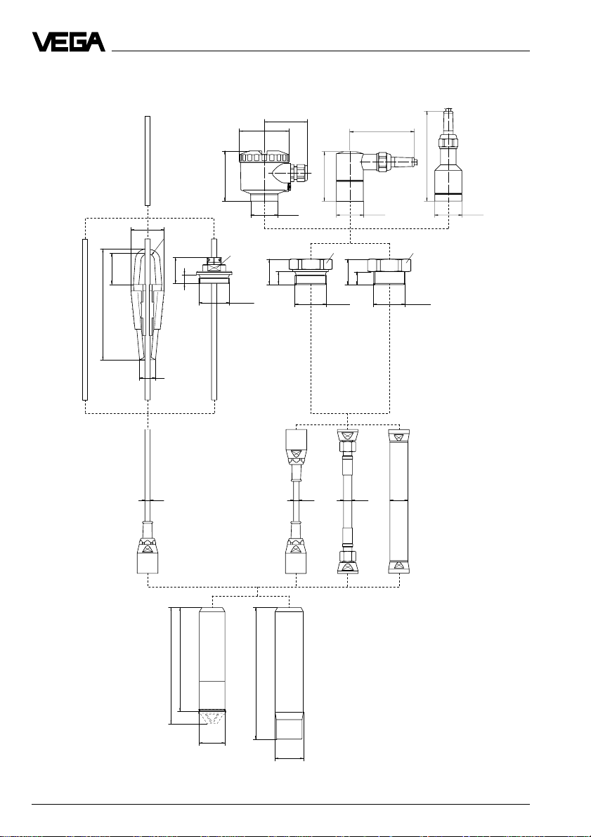
1.7 Dimensions
Product description
C3 D3
100
139
77
77
A1, A2, B1, B2
66
ø 76
C1
52
R 11
49
175
41
14
25
X4 A4 V4
ø 10
K
ø 41,6
SW 30
G 1½ A
39
14
SW 60
G 1½ A
G4 N4
ø 10 ø 13 ø 28
KS R
XP
ø 41,6 ø 41,6
SW 60
39
14
1½" NPT
162
181
ø 40
205
ø 44
14 Pressure transmitters D86/D87
Page 15

Product description
VEGABOX 01
38 72
ø 5
M20x1,5
with protective cover
135
118
108
139
85
72100
130
Pressure transmitters D86/D87 15
Page 16
2 Mounting
Mounting
2.1 Mounting instructions
The pressure transmitter can be mounted in
any position. Cable entries must point downwards to avoid moisture ingress. For this
purpose, the housing can be rotated by 330°
in relation to the mounting part.
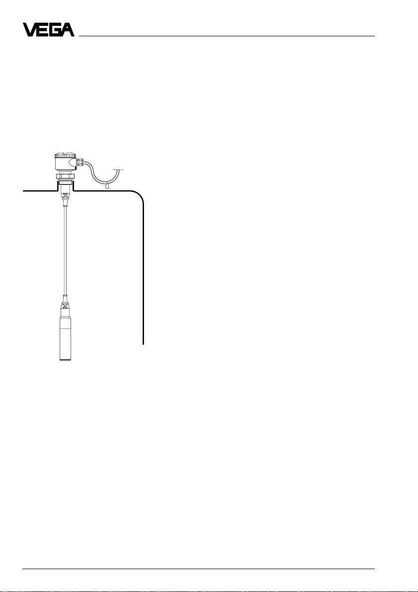
2.2 Compensation of the atmospheric pressure
On instruments for gauge pressure measurement, the atmospheric pressure is compensated via a breather facility integrated in
the housing.
Pressure transmitter with direct cable
outlet
- via the capillaries of a special cable con-
nected to the terminals, protection IP 68
We recommend leading the special cable into
the external connection housing VEGABOX
01 (accessory) and carrying out the pressure compensation via the integrated
breather facility there.
External connection housing
Observe the following instructions:
- as a rule, there must be the same atmos-
pheric pressure on the breather facility as
on the vessel
- the pressure compensation must be done
in a dry environment
- with vertical wall mounting, cable entries
must point downward to avoid moisture
ingress and buildup on the breather facility.
An appropriate connection seal must be
used for mounting. This seal is either supplied with the pressure transmitter or must be
provided by the customer.
16 Pressure transmitters D86/D87
Pressure transmitter with housing
- via an integrated breather facility (PTFE
use 1)), protection IP 66
- via the capillaries of a special cable con-
nected to the terminals, protection IP 67
1)
air permeable and humidity blocking
Page 17

Electrical connection
3 Electrical connection
3.1 Connection instructions
The electronics in the pressure transmitter
requires a supply voltage of 12 … 32 V DC. It
is designed in two-wire technology, i.e. the
supply voltage and the digital output signal
are led via the same two-wire cable to the
terminals.
This external energy is provided via a separate power supply unit, e.g.:
- power supply unit VEGASTAB 690
- processing unit with integrated DC voltage
source (e.g. active PLC input)
- VEGAMET, VEGALOG or VEGADIS 371
Make sure that the external energy source is
reliably separated from the mains circuits
acc. to DIN VDE 0106, part 101. The abovementioned VEGA devices meet this requirement and protection class III is therefore
guaranteed.
The external energy source must provide a
terminal voltage of at least 12 V on the transmitter. The actual terminal voltage on the
transmitter depends on the following factors:
- output voltage UH of the external energy
source under nominal load.
- electrical resistance of the connected instruments in the circuit (see connected
instruments, load resistance).
Note the following instructions for electrical
connection:
- Connection must be made according to the
country-specific installation standards (e.g.
in Germany acc. to the VDE regulations).
- The terminal voltage must not exceed 36 V,
to avoid damage to the electronics.
- The electrical connection must have a protective measure against polarity reversal.
- Connection of Ex sensors only by qualified
personnel.
- The wiring between pressure transmitter
and power supply can be made with
standard two-wire cable.
- If strong electromagnetic interference is
expected, screened cable is recommended. The screening must be done on
both ends. Note the installation regulations
for use in Ex areas.
- In case of overvoltages, we recommend
the use of pressure transmitters with integrated overvoltage protection or the installation of VEGA overvoltage arresters.
- In the cable entry, a seal correctly fitting the
cable should be used.
Safety information for Ex applications
As a rule, do all connecting work in the complete absence of line voltage. Always switch
off the power supply before you carry out
connecting work on the sensors. Protect
yourself and the instruments.
Qualified personnel
Instruments used in Ex areas must be installed only by qualified personnel. The qualified personnel must observe and understand
the mounting regulations and the supplied
type approval certificates and conformity
certificates.
If an instrument is used in hazardous areas,
the respective regulations, conformity certificates and type approvals of the sensors,
separators or safety barriers must be noted
(e.g. DIN VDE 0165).
Pressure transmitters D86/D87 17
Page 18

Electrical connection
Sensors used in Ex areas must be connected only to intrinsically safe circuits. The
permissible electrical values are stated in the
conformity certificate or the type approval
certificate.
Intrinsically safe circuits with more than one
active instrument (instrument delivering electrical energy) are not allowed. Please note the
special installation regulations (DIN VDE
0165).
Certain pressure transmitters are provided
with a warning label informing of measures to
be taken to avoid the danger of electrostatic
discharge. Note the content of the warning
label.
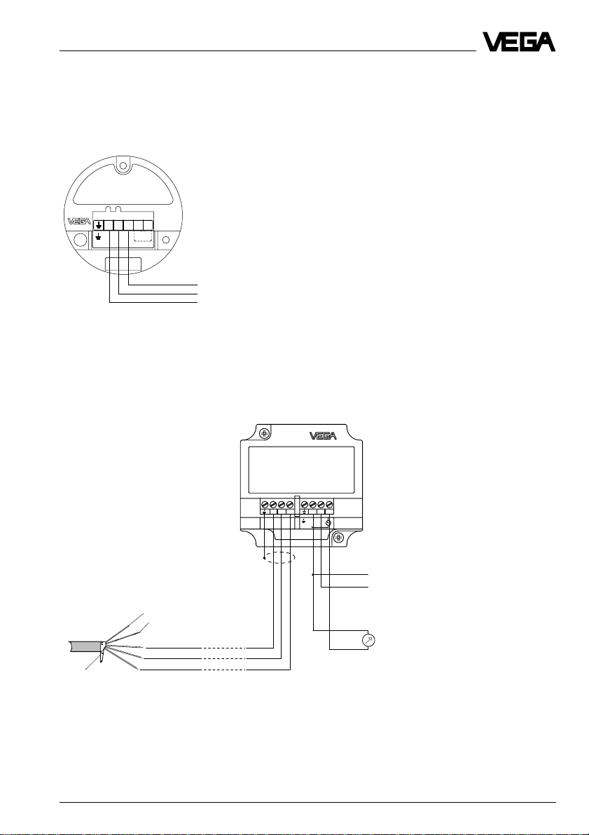
3.2 Terminal assignment
Direct cable outlet
Breather capillaries
Suspension cable
br
+
bl
-
ge
For supply or to the process-
(only for adjustment insert in
Screen
Electronics version A
for connection to VEGA signal conditioning
instruments
ing system (4 … 20 mA,
external housing)
12 … 36 V DC or VBUS)
Electronics version B
Digital output signal for connection to a digital
VEGA signal conditioning instrument (VBUS)
Zum Anschluss an
For connection to
VBUS-Auswertgeräte
VBUS-signal conditioning instruments
1234
-+
-+
Klemmeinsatz
terminal
V
Field
Communication
BUS
Internal connection
Supply and digital
measuring signal from
and to the digital
VEGAMET 514V and
515V signal condition-
–
ing instrument or
VEGALOG 571
+
processing system
Electronics version I
4 … 20 mA output signal, remote parameter
setting through PC and HART® handheld
4-20mA
-
+
4...20mA
12V...36V DC
Klemmeinsatz
terminal
51234
+
–
–
Power supply
+
12 … 36 V DC
Electronics version K
4 … 20 mA output signal with integrated
adjustment and remote parameter setting
through PC and HART® handheld
Zum Anschluss an
For connection to
VEGA-Auswertgeräte
VEGA-signal conditioning instruments
51234
-
+
Klemmeinsatz
terminal
+
–
Supply or processing
from the VEGAMET
–
signal conditioning
instrument
+
12 … 36 V DC
S
Zt
+
-
4...20mA
12V...36V DC
Bedieneinsatz
operating unit
Op
i
43215
+
–
–
Power supply
12 … 36 V DC
+
18 Pressure transmitters D86/D87
Page 19
Electrical connection
Electronics version L
4 … 20 mA output signal with adjustability via
the external connection housing VEGADIS
12, as well as remote parameter adjustability
via PC and HART® handheld
Zum Anschluss an
For connection to
VEGADIS 12
51234
-
+
12V...36V DC
Klemmeinsatz
terminal
Connection housing
VEGADIS 12
3.3 Connection to external connection housing VEGABOX 01
Adjustment insert in external
connection housing
Zum Anschluss an
For connection to
Druckmessumformer mit
pressure transmitters with
analogem Ausgangssignal
analog output
1
Pressure transmitter with direct cable
outlet
231011 12
TRANSMITTER
VEGABOX 01
+
4... 20mA
-
+
+
For supply or to the processing
system (4 … 20 mA, 12 … 36 V DC)
–
Breather capillaries
Suspension cable
+
br
bl
–
ge
+
Control instrument (4 … 20 mA
measurement)
–
Screen
Pressure transmitters D86/D87 19
Page 20
Electrical connection
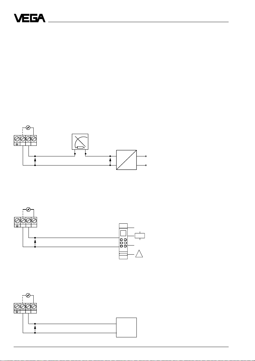
3.4 Connection examples
Note:
An ammeter for local control of the output current can be connected to terminals 1 and 3. This
measurement can be carried out during operation without interrupting the supply cable.
The following connection examples are valid for direct connection to the terminals of the pressure transmitter. When using the external connection housing, the connection is made to the
respective terminals of the housing.
Supply through a power supply unit
Processing is done by an indicating instrument.
Ammeter for local control
analogue / digital indicating
+ - -
1 2 3
Pressure transmitter terminals
instrument
External energy source
U
U
K
4 … 20 mA
A
-
U
H
~
+
Supply through a VEGA signal conditioning instrument
Standard wiring for non-standardised output.
Ammeter for local control
+ - -
1 2 3
Pressure transmitter
terminals
U
K
Analogue transmission,
non-standardised
0/4 … 20 mA
DISBUS
!
Supply through a PLC with active input circuit
Processing is done by the PLC
Ammeter for local control
+ - -
1 2 3
Pressure transmitter
terminals
U
K
4 … 20 mA
PLC
+
20 Pressure transmitters D86/D87
Page 21

Setup
4 Setup
4.1 Adjustment structure
The hydrostatic pressure transmitters come
with or without adjustment capability.
After connection to the supply voltage, the
electronics carries out a self-test (approx.
2 sec.) and the current in this signal circuit
(sensors with analogue output signal) takes
on a value of > 21.6 mA.
Sensors with adjustment
(electronics version A and C)
Sensors with electronics version A deliver a
pressure-proportional current as measured
value and are not adjustable. All settings
such as adjustment, density correction etc.
are carried out via the signal conditioning
instrument. The sensors with electronics
version C come preadjusted according to the
measuring range of the sensor (factory setting). In unpressurised condition, they consume a current of 4 mA. With a pressure at
the measuring range final value, they consume a current of 20 mA.
Sensors with adjustment insert in the
sensor (electronics version K)
The adjustment insert with selection switch
allows:
- zero adjustment
"z" = empty adjustment
- span adjustment
"s" = full adjustment
- adjustment of an integration time (time) "ti"
Adjustment in external connection housing VEGADIS 12 (electronics version L)
The adjustment insert with selection switch
(VEGADIS 12 with display) allows:
- zero adjustment
- span adjustment
- adjustment of an integration time (time)
- adjustment of a value for zero point
(empty)
- adjustment of a value for span (full)
- adjustment of the decimal point for the
displayed value
Adjustment with HART® handheld
(electronics version I, K and L)
The hydrostatic pressure transmitters with
electronics version I, K and L can be adjusted with the HART® handheld like other
HART® capable instruments. A manufacturer
specific DD (Device Description) is not necessary. The sensors work with the HART
standard menus.
Adjustment of VEGA signal conditioning
instrument VEGAMET (electronics version
A and B)
Electronics version A delivers a non-standardised output signal to a VEGAMET with
analogue input.
Electronics version B transfers the measured
value digitally (VBUS) to a digital VEGAMET
(514V, 515V, 614V).
The signal conditioning instrument itself, as
well as the pressure transmitter, can be operated by means of the standard six-key adjustment field (with clear dialogue text
display) on the signal conditioning instrument.
®
Pressure transmitters D86/D87 21
Page 22
Setup
Bedieneinsatz
operating unit
S
Zt
i
Op
43215
+
-
12V...36V DC
4...20mA
1
2
3
Adjustment with PC and adjustment
program VVO (electronics version B, I, K
and L)
With the adjustment program VVO (VEGA
Visual Operating) on the PC you can conveniently adjust the pressure transmitters with
electronics version B, I, K and L. The PC
communicates with the sensor through the
interface converter VEGACONNECT 2 or the
standard RS 232 interface cable. A digital
adjustment signal is superimposed on the
signal and supply cable. The adjustment can
be carried out from any location on the signal
cable, on the sensor directly, on the signal
conditioning instrument or on the VEGALOG
processing system.
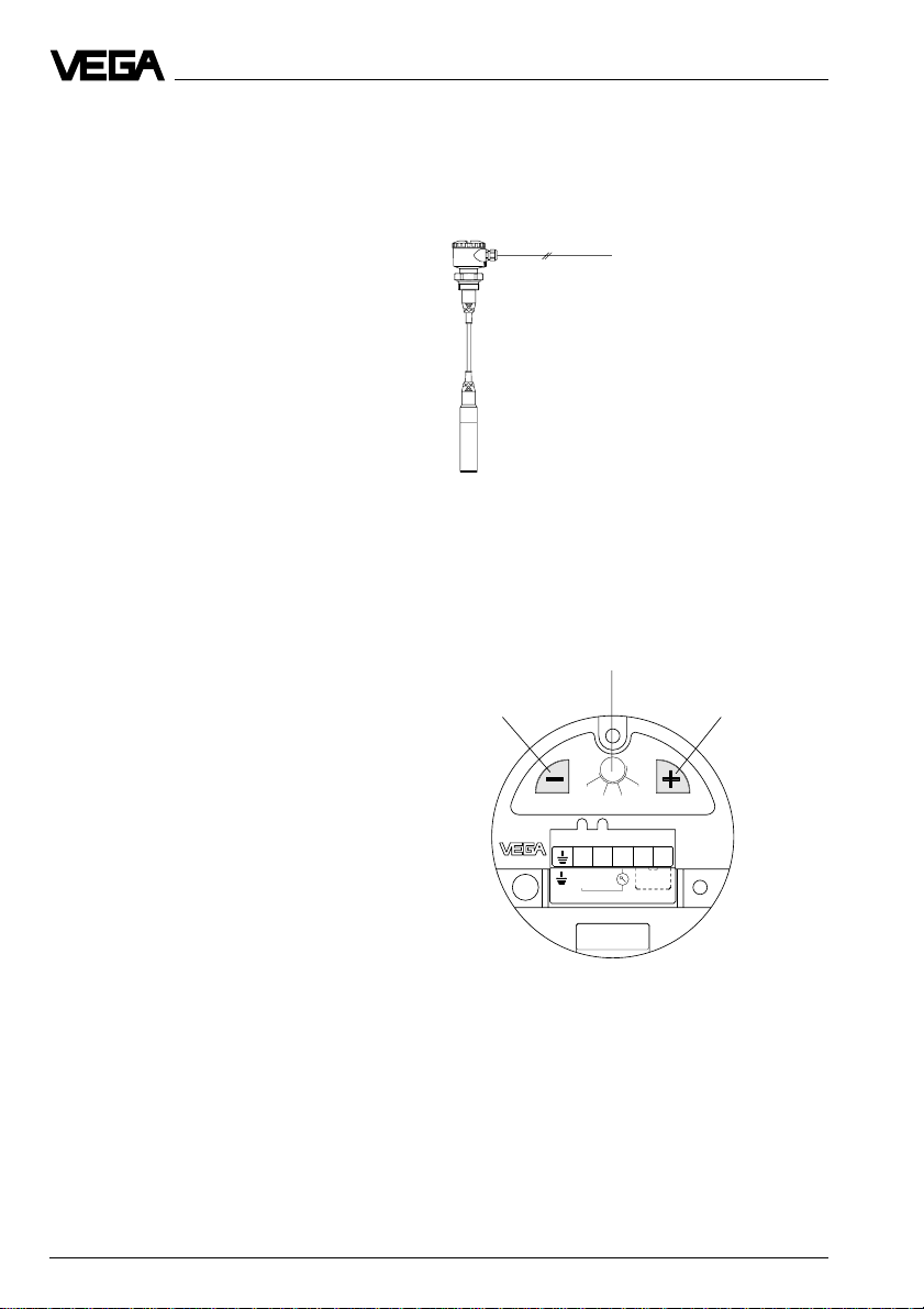
4.2 Sensor without adjustment
Sensors with electronics version C have no
adjustment capability and come preset to the
stated measuring range.
4.3 Sensor with adjustment insert, adjustment in the sensor
Sensors with electronics version D and K are
equipped with an adjustment insert.
1 Reduce value
2 Rotary switch
3 Increase value
With the rotary switch you can select four
switch positions:
s - span
z - zero
22 Pressure transmitters D86/D87
ti - time (integration time)
Op - operate (operating status)
Page 23

Setup
S
Op
Zt
i
43215
+
-
4...20mA
12V...36V DC
Bedieneinsatz
operating unit
Adjustment
For adjustment of zero and span, an ammeter must be connected to terminals 1 and 3.
The measured value is identical to the output
current.
1 Adjustment of zero
(e.g. empty vessel)
• Set rotary switch to zero.
• By pushing the "+" and "–" keys simultane-
ously, the current jumps directly to 4 mA or
you can adjust a current of 4 mA with the
"+" and "–" keys.
Note:
- A modification of zero does not influence
the span, i.e. the measuring range final
value is simply shifted.
- It is also possible to adjust currents for
partial fillings or partial pressures, e.g.
8 mA for 25 % and 16 mA for 75 %.The
pressure transmitter then automatically
calculates the values for 0 % or 100 %
(only possible with a level difference
>3.3 %).
Integration time
An integration time ti of 0 … 10 s can be adjusted to damp pressure shocks.
Procedure
• Set rotary switch to ti.
• By pushing the "-" 10 times, make sure that
the integration time is set to 0 s.
• For each 1 s desired integration time, the
"+" key has to be pushed once.
Adjustment range of zero:
-20 % … +95 % of nominal measuring range
(corresponds to a turn up of up to +95 %)
2 Adjustment of span
(e.g. level at maximum)
• Set rotary switch to span.
• By pushing the "+" and "–" keys simultane-
ously, the current jumps directly to 20 mA
or you can adjust a current of
20 mA with the "+" and "–" keys.
Adjustment range of span:
3.3 % … 120 % of nominal measuring range
(corresponds to a turn down 1 : 30)
Pressure transmitters D86/D87 23
Page 24

Setup
4.4 Setup with HART® handheld
Sensors with electronics versions I, K and L
can be set up with the HART® handheld. A
special DD (Data Device Description) is not
necessary. Just connect the HART® handheld
to the sensor signal cable after you have
connected the sensor to supply voltage.
250
W
Note:
If the resistance of the voltage supply is less
than 250 W, a resistor must be looped into the
signal/connection cable during adjustment.
The digital adjustment and communication
signals would otherwise be short-circuited
through insufficient resistance of e.g. the
supply voltage source or the processing
system. In such case, communication with
the sensor would not be ensured. Simply
connect the adjustment resistor in parallel to
the connection socket of the HART
®
handheld.
+
PLC
-
Ri < 250
W
24 Pressure transmitters D86/D87
Page 25
Setup
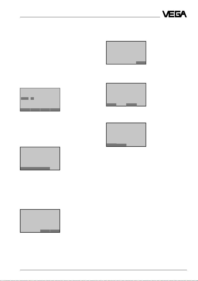
The most important adjustment steps
On the following four pages you see a menu
schematic of the HART® handheld in conjunction with pressure transmitters D80 … D87.
The most important adjustment steps are
marked in the menu schematic with the letters
A … D. If you are not familiar with HART
handheld, please note:
After entering a parameter, first push the
"
ENTER
" key. The adjustment is saved in the
handheld, but not in the sensor itself.
Generic: SENSOR
PV LVR
0.000 mbar
10.000 mbar
HELP DEL ESC ENTER
Empty adjustment without
medium
After you have pushed "
push "
SEND
" (here in the example for the
4.1
(5.1)
ENTER
", you have to
min. adjustment), to transfer the input to the
sensor.
Generic: SENSOR
1 PV LRV
2 PV URV
®
After a moment, you are asked to switch the
system from manual to automatic operation.
Confirm with "OK"
Generic: SENSOR
– WARNING –
Return control loop to
automatic control
OK
and then with "
Generic: SENSOR
1 PV LRV
2 PV URV
HELP HOME
HOME
".
You are now in the initial menu.
Generic: SENSOR
Online (general)
1 Sensor unit
2 P V 80.945 mbar
3 PV Analog output
4 PV LRV
5 PV URV
HELP SAVE
HELP SEND HOME
After pushing "
SEND
", a warning is displayed
that you are about to change device output
and for safety reasons, you should switch
your system to manual operation. Push "OK"
and the adjustment is now transferred to the
sensor.
Generic: SENSOR
– WARNING –
Pressing „OK“ will
change device output
Put loop in manual
ABORT OK
Pressure transmitters D86/D87 25
Page 26

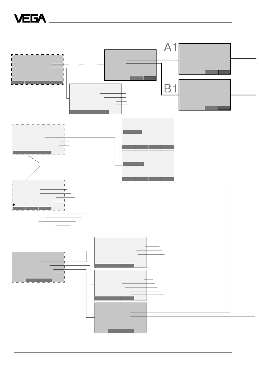
HART® menu schematic
Switch on:
Hart Communicator
Self T est
in Progress
Firmware Rev: F2.2
Module Rev: 3.6
01992-96 FRSI
after approx.
20 s
Generic: D84
Online(Generic)
1 Device setup
2 P V 80.007 mbar
3 PV AO 17.594 mA
4 P V LRV 0.000 mbar
5 URV 100.000mbar
HELP SAVE
Set up the sensor in the sequence of the
letters A, B, C and D (adjustment without
medium).
For the adjustment with medium you set
up the sensor in the sequence A1, B1, C
and D.
Generic: D84
Device setup
1 Process variables
2 Diag/Service
3 Basic setup
4 Detailed setup
5 Review
SAVE HOME
Generic: D84
PV
84.558 mbar
HELP EXIT
Generic: D84
AO1
17.518 mA
HELP EXIT
1
2
3
Generic: D84
Process variables
1 Snsr 84.293 mbar
2 AI % rnge 84.265 %
3 AO1 17.478 mA
HELP SAVE HOME
Generic: D84
1 PV LRV 0.000 mbar
2 URV 100.000 mbar
HELP HOME
Generic: D84
– WARNING –
Return control loop to
automatic control
Generic: D84
– WARNING –
Pressing „OK“ will
change device output
Put loop in manual
ABORT OK
Generic: D84
1 PV LRV 0.000 mbar
2 URV 100.000 mbar
Setup
1.1
OK
HELP SEND HOME
4.1
(5.1)
4.2
(5.2)
Important and
required menu
windows
Less important
menu windows
Not required, unimportant
or blocked menu windows
Generic: D84
1 PV LRV 0.000 mbar
2 URV 100.000 mbar
HELP HOME
Generic: D84
1 PV LRV 0.000 mbar
2 URV 100.000 mbar
HELP HOME
continue like under 4
Generic: D84
PV LRV
4
5
0.000 mbar
0.000 mbar
HELP DEL ESC ENTER
Empty adjustment without
medium
Generic: D84
PV URV
100.000 mbar
100.000
HELP DEL ESC ENTER
Full adjustment without
medium
continue like under
A figure 4.1(5.1)
26 Pressure transmitters D86/D87
Page 27

Setup
Generic: D84
PV
83.454 mbar
HELP EXIT
Generic: D84
PV % rnge
83.385 %
HELP EXIT
Generic: D84
AO1
17.327 mA
HELP EXIT
Generic: D84
Diag/Service
1 T est device
2 Loop test
3 Calibration
4 D/A trim
SAVE HOME
Generic: D84
Basic setup
1 Tag
2 PV Unit
3 Range values
4 Device information
5 PV Xfer fnctn
HELP SAVE HOME
6 PV Damp
1.1.1
Safety
enquiry
acknowledgement
1.1.2
1.1.3
1.2
Blocked menu. The
following menu window is
indicated but not supported
by the sensor. Therefore
saving of adjustments
carried out here is not
possible.
1.3
Transmission function
(linear)
Generic: D84
Choose analog output
level
1 4 mA
2 20 mA
3 Other
4 End
ABORT ENTER
Generic: D84
Calibration
1 Apply values
2 Enter values
HELP SAVE HOME
Generic: D84
Tag
BAR 20
BAR 20
HELP DEL ESC ENTER
Generic: D84
PV Snsr unit
mbar
mbar
g/cm2
kg/cm2
Pa
Generic. D84
Range values
1 PV LRV 0.000 mbar
2 URV 100.000 mbar
3 PV LSL 0.000 mbar
4 USL 100.000 mbar
HELP HOME
Generic: D84
Device information
1 Distributor
2 Model Generic
3 Dev id 11017815
4 Tag D84
5 Date 10/01/97
HELP SAVE HOME
6 Write protect None
7 Description
8 Message
9 PV Snsr. s/n
Generic: D84
PV Damp
1.2.2
Input of individual current
values for test purposes
(simulation of measured
value)
1.2.3
ESC ENTER
Final asmbly num 0
Revision #’s
1.000 s
1 .000 s
Empty and full
adjustment
with medium
}
(see next page)
1.3.1
Newly assigned
measurement loop
designation to be
saved with ENTER
and SEND
1.3.2
1.3.3
see
next
}
page
1.3.4
see
next
}
page
1.3.6
HELP DEL ESC ENTER
Generic: D84
Review
Model
Generic
HELP PREV NEXT EXIT
NAECH VERL.
1.5
Generic: D84
Detailed setup
1 Sensors
2 Signal condition
3 Output condition
4 Device information
SAVE HOME
1.4
}
see
next
page
Pressure transmitters D86/D87 27
Page 28
Setup
HART® menu schematic (continuation)
Generic: D84
Calibration
1 Apply values
2 Enter values
HELP SAVE HOME
Generic: D84
Range values
1 PV LRV 0.000mbar
2 PV URV 95.981mbar
3 PV LSL 0.000mbar
4 USL 100.000mbar
HELP HOME
Menu fields (broken line):
repetition of previous page
Generic: D84
Device information
1 Distributor
2 Model Generic
3 Dev id 11017815
4 Tag D84
5 Date 01/01/97
HELP SAVE HOME
6 Write protect None
7 Descriptor
8 Message
9 PV Snsr s/n
Final asmbly num 0
Revision #’s
Generic: D84
Detailed setup
1 Sensors
2 Signal condition
3 Output condition
4 Device information
SAVE HOME
1.2.3
Safety
enquiry
1.2.3.1
acknowledgement
Generic: D84
Enter values
1 PV LRV 0.000 mbar
2 URV 100.000 mbar
3 PV USL
4 PV LSL 0.000 mbar
HELP HOME
1.3.3
Indication of the
}
sensor measuring
range limits
1.3.4
Unknown Enumerator
General
(1.3.4.3) Indication of the sensor serial number
(1.3.4.4) Measurement loop designation as under menu window 1.3.1
(1.3.4.5) Date adjustment
individual text adjustment
individual text adjustment
Indication of the sensor serial number (as under menu window 1.3.4.3)
1.4
like menu 1.3.4
Generic: D84
Set the:
1 4 mA
2 20 mA
3 Exit
None
Generic: D84
Sensors
1 P V 97.214 mbar
2 PV Snsr unit mbar
3 Sensor information
HELP SAVE HOME
Generic: D84
Signal condition
1 Snsr Damp 1.000 s
2 URV 100.000 mbar
3 AI LR V 0.000 mbar
4 Xfer fnctn Linear
5 AI % rnge 97.101 %
HELP SAVE HOME
Generic: D84
Output condition
1 Analog output
2 HART output
1.2.3.1
ABORTENTER
1.2.3.2
like display 4.1
like display 4.2
Indication of the
}
sensor measuring
range limits
Generic: D84
PV LRV
0.000 mbar
0.000
HELP DEL ESC ENTER
Generic: D84
PV URV
100.000 mbar
100.000 mbar
HELP DEL ESC ENTER
1.3.3.1
1.4.1
Measured value
Modification of the unit
Info on lower and upper measur-
ing range limit as well as min.
span (also the sensor characteris-
1.4.2
1.4.3
tics values)
Adjustment of the integration time
Adjustment of zero and span
Adjustment of zero and span
linear
Indication of the level in % of the
adjusted span
Empty adjustment with
medium
Generic: D84
Apply new 4 mA input
Generic: D84
Apply new 20 mA input
Full adjustment with
medium
1.3.3.2
ABORT OK
ABBR. OK
SAVE HOME
28 Pressure transmitters D86/D87
Page 29

Setup
Generic: D84
Current applied
process value: 97.112
mbar
1 Set as 4 mA value
2 Read new value
3 Leave as found
ABORTENTER
Generic: D84
Current applied
prosess value :96.262
mbar
1 Set as 20 mA value
2 Read new value
3 Leave as found
Generic: D84
Analog output
1 AO1 19.920 mA
2 AO Alrm typ
3 Loop test
4 D/A trim
5 Scaled D/A trim
HELP SAVE HOME
1.2.3.1.1
ABORT ENTER
1.2.3.1.2
1.4.3.1
Generic: D84
Set the:
1 4 mA
2 20 mA
3 EXIT
Generic: D84
Set the:
1 4 mA
2 20 mA
3 Exit
Generic: D84
AO Alrm typ
Lo
Generic: D84
WARN - Loop should be
removed from
automatic control
Menu windows are displayed but not
}
supported by the sensor.
Saving of adjustments carried out here is
therefore not possible.
1.2.3.1.1.1
ABORT ENTER
ABORT ENTER
1.2.3.1.2.1
1.4.3.1.2
EXIT
1.4.3.1.3
ABORT OK
1.4.3.1.3
Generic: D84
Current applied
process value: 96.549
mbar
1 Set as 4 mA value
2 Read new value
3 Leave as found
Generic: D84
Current applied
process value: 95.703
mbar
1 Set as 20 mA value
2 Read new value
3 Leave as found
Generic: D84
Fld dev output is
fixed at 4.000 mA
Generic: D84
Apply new 4 mA input
ABORT OK
Generic: D84
Apply new 20 mA input
ABORT OK
Low: In case of failure, current output
goes to 22 mA
High: In case of failure, current output
goes to < 3.6 mA
Generic: D84
Choose analog output
level
1 4 mA
2 20 mA
3 Other
4 End
ABORTENTER
ABORT ENTER
ABORT ENTER
1.4.3.1.3.1
ABBR. OK
1.4.3.2.3
ESC ENTER
1.4.3.2.4
Off
On
Not used
None
Unknown
Special
Leave the Burst-mode in
OFF position
Choice is not supported
Sensor signals measured values only on
request
Sensor signals measured values
unrequested
Choice is not supported
Generic: D84
HART output
1 Poll addr 0
2 Num req preams 5
3 Burst mode Off
4 Burst option
HELP SAVE HOME
1.4.3.2
Generic: D84
Burst mode
Off
Off
On
Not Used
None
Generic: D84
Burst option
*********
PV
% range/current
Process vars/crnt
HELP ESC ENTER
Note:
After entering a parameter, push "
ENTER
" and then "
SEND
".
Confirm the message to switch over to manual operation with "OK".
Confirm the message to reset to automatic operation also with "OK".
Only then will the adjustment be stored in the sensor and take effect.
Pressure transmitters D86/D87 29
Page 30

Setup
5.5 Adjustment with PC directly on the sensor
(electronics versions I, K and L)
For connection of the PC to the sensor, the interface converter VEGACONNECT 2 is required.
Connection of the PC to the sensor
Insert VEGACONNECT into the serial interface on of the PC and insert the two-wire cable of
VEGACONNECT into the CONNECT socket of the sensor.
Connection of the PC to the signal cable
Connect the two-wire cable of VEGACONNECT 2 to the signal cable leading to the sensor.
Connection configuration with pressure transmitter directly on active PLC
(electronics versions I, K and L)
• Two-wire technology, power supply from active PLC.
• Output signal 4 … 20 mA (passive).
• Adjustment with PC, HART® handheld or adjustment insert located in the sensor or in the
external connection housing.
1)
2
4 ... 20 mA
2
VEGACONNECT 2
30 Pressure transmitters D86/D87
2
1)
If the resistance of the processing system (PLC)
connected to the 4 … 20 mA signal output is less
than 200 W, a resistor of 250 W must be connected
to the connection cable during adjustment.
The digital adjustment signal would be considerably
damped or short-circuited through insufficient
resistance of a connected processing system, and
digital communication with the PC would not be
ensured.
PLC
Ri < 250
W
Page 31

Setup
If you have already connected the PC with
the adjustment software VVO to your measuring system,
• first switch on the power supply of the
connected sensor
• switch on the PC and start the adjustment
software VVO.
• Choose with the arrow keys or the mouse
the item "
Planning
" on the entrance screen
and click to "OK".
You are asked for user identification.
The adjustment program (VVO), called in the
following VVO, gets into contact with the
connected sensor…
…and indicates after a few seconds if and
with which sensor a connection exists.
The preset user identification can be modified
later in the menu "
User access
".
• Enter under name "
• Also enter "
Pressure transmitters D86/D87 31
VEGA
VEGA
" under password.
".
Page 32

Note:
If you connect the adjustment software (VVO)
to a sensor from which data has already
been saved, you are asked if the saved data
should be transferred to the sensor or if you
want to transfer the sensor data to the database of VVO (the available data of the current sensor will be overwritten).
If you don’t get communication with the sensor, check the following:
- Is the sensor being supplied with sufficient
voltage (min. 12 V)?
- When VEGACONNECT 2 is connected to
the signal cable, is the load resistance
250 … 350 W?
Configuration
• Choose the menu "
system
", to get further information on the
sensor type, the software version of the
sensor, measuring unit, the measurement
loop designation etc.
Configuration/Measuring
Setup
In the menu "
you can give a name (e.g. vessel 10) and a
description (e.g. cleaning detergent) to the
measurement loop in place of the sensor
number. This will make your entire measuring
system more understandable.
• Now enter in this menu whether a level, a
distance or a gauge should be measured.
Modify meas. loop configuration
"
• Click to "
• Click to the menu "
ment loop/Modify
sensor setup.
32 Pressure transmitters D86/D87
Quit
".
Configuration/Measure-
". This is the first step of
• Confirm the adjustment with "OK" and after
saving you are again in the initial menu.
Page 33

Setup
Parameter adjustment/Adjustment
In the menu "
justment
adjustments.
• Choose the menu "
eter adjustment
Instrument data/Parameter ad-
" you carry out all important sensor
Instrument data/Param-
".
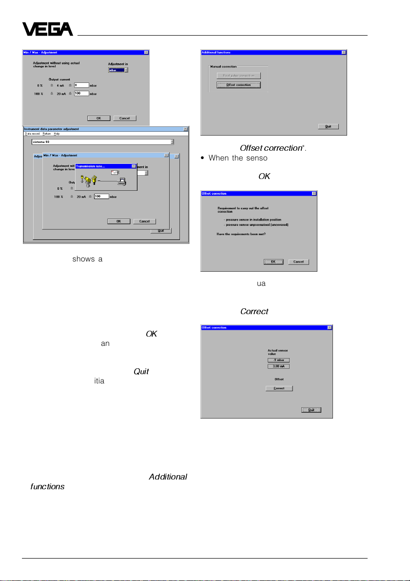
• Choose in the menu window "
data parameter adjustment
"
Adjustment
• In the menu window "
to "
Min/Max-adjustment
You can carry out the min./max. adjustment
with or without medium. Generally you will
carry out the adjustment without medium.
".
Adjustment
Instrument
" the menu item
" you click
" (zero/span).
The adjustment can be quickly and conveniently carried out without medium, as shown
in the example.
• Choose in which unit you want to carry out
the adjustment.
• Enter the pressures corresponding in your
• Confirm the warning with "OK".
In the heading you now see the previously
entered measurement loop name and the
measurement loop description.
Pressure transmitters D86/D87 33
application to 0 % and 100 % and push
"OK".
Page 34
Setup
The example shows an absolute pressure
transmitter with a measuring range of
0 … 1000 mbar, with which low pressures
(partial vacuum) are measured. The min.
value was set to 50 mbar and the max. value
(span) to 1000 mbar (i.e. the final value of the
measuring range).
• Confirm your adjustments with "OK" and
after a short data transmission to the sensor, you are again in the menu window
"
Adjustment
• Quit all menu windows with "
".
Quit
" and you
are again in the initial menu.
Offset correction (not possible with absolute pressure transmitters)
With this menu you can carry out a zero point
correction/position correction (unpressurized
sensor).
• Click to "
Offset correction
".
• When the sensor is unpressurised and in
installation position, confirm the safety
enquiry with "OK".
You see the actual measured value from the
sensor.
• Click to "
Correct
".
• Choose in the initial menu "
Parameter adjustment
functions
34 Pressure transmitters D86/D87
".
Instrument data/
" the item "
Additional
Page 35
Setup
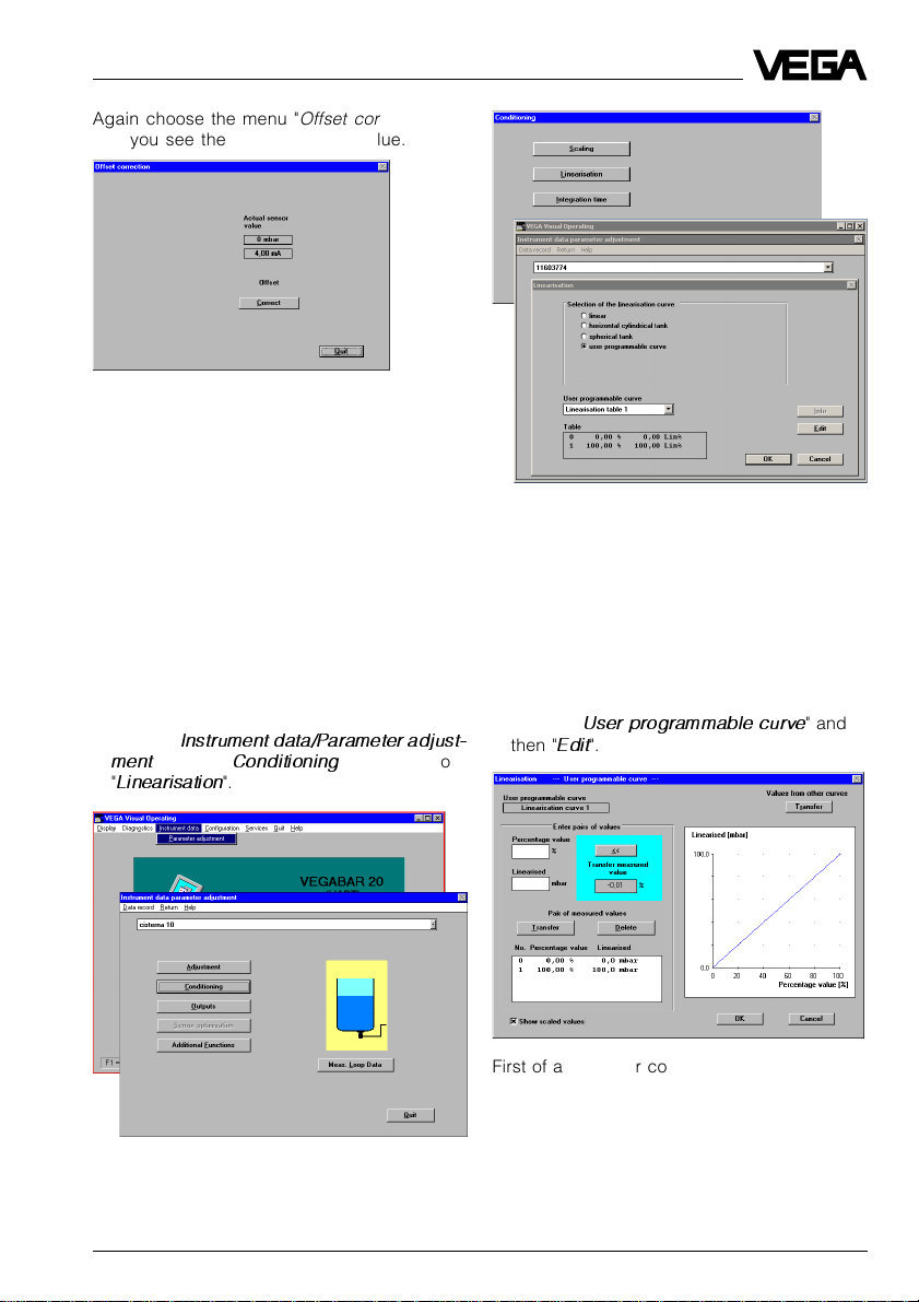
Again choose the menu "
and you see the corrected zero value.
Note:
The menu item "
bles the correction of the actual pressure by
means of a reference value. This corrects the
measuring characteristics in a way similar to
the offset correction.
Real value correction
Offset correction
" ena-
"
Conditioning/Linearisation
In the menu "
justment/Conditioning/Linearisation
cated a filling quantity (volume) to the level
(filling height). The correlation between level
and volume is described with so-called
linearisation curves.
• Click to "
ment
"
Linearisation
Instrument data/Parameter ad-
" you allo-
Instrument data/Parameter adjust-
", then to "
Conditioning
".
" and finally to
You can choose four linearisation curves:
linear, horiz. cylindrical tank, spherical tank
and user programmable curve.
Under "
User programmable curve
enter your own linearisation curve as a correlation between the level in % or pressure in %
(percentage value) and the volume
(linearised).
• Choose "
then "
User programmable curve
Edit
".
" you can
" and
First of all, a linear correlation is displayed
(the function is a straight line).
Pressure transmitters D86/D87 35
Page 36

Setup
In the field "
Transfer measured value
" the
current pressure as a percentage of the
adjusted span is displayed. The measuring
span has already been adjusted with the
min./max adjustment. In our example this is in
the range between 50 … 1000 mbar.
The user-programmable linearisation curve is
generated by index markers, consisting of
the value pairs "
the selected unit) and "
Linearised
Percentage value
" (volume in % or in
"
(level or filling height in %).
Defining the linearisation curve by incremental filling
In the characteristics of the example (evacuated vessel), you see four index markers or
value pairs. There is always a linear interpolation between the index markers.
• Click in the check box "
ues
", to have the selected unit of measure-
Show scaled val-
ment displayed on the y-axis (left bottom
part in the menu window).
Index marker 1 is at 0 % level or pressure
(percentage value [%]), corresponding to an
actual pressure of 0 mbar.
Index marker 2 is at 30 % level or pressure
and 5 % filling volume.
Index marker 3 is at 70 % level or pressure
and 35 % filling volume.
Pressure
transmitter
Vacuum
Saline
solution
1000 mbar
= 100 liters
700 mbar
= 35 liters
300 mbar
= 5 liters
0 mbar
= 0 liters
Max. 32 index markers (value pairs) can be
entered.
• Quit the menu with "OK".
• Confirm the message with "OK" and your
individual linearisation curve will be saved
in the sensor.
Again in the menu window "
Conditioning
" you
can enter a measured value integration with
the menu item "
Integration time
". This is useful
for fluctuating product surfaces to smooth the
display and output of measured values. As a
standard feature, the integration time is preset to 0 seconds.
• Quit the menu with "OK".
You are again in the menu window
data parameter adjustment
Instrument
".
Index marker 4 is at 100 % level or pressure
and 100 % filling volume (100 litres).
36 Pressure transmitters D86/D87
Page 37
Setup
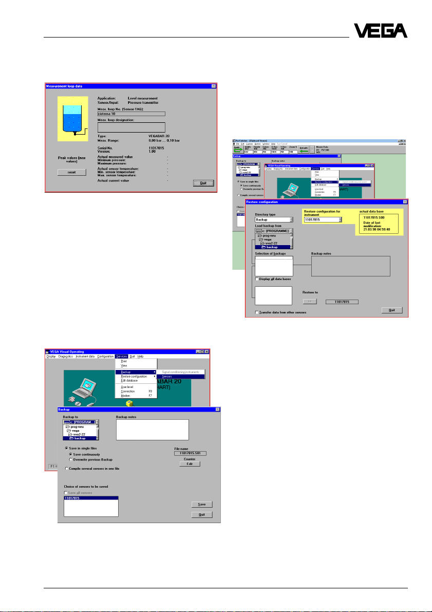
Meas. data information
• Click to "
All available sensor information is displayed.
With the button "
pressure and temperature history saved in
the sensor.
Meas. data info
reset
" you can delete the
".
Backup
In the menu window "
its serial number is displayed. You can save
the sensor data in the PC individually or in
groups with all adjustments in a directory of
your choice. A small text message can be
added to each backup.
Backup
" the sensor with
Saved sensors data can be transferred later
on to other sensors.
For example, if you have a system with several of the same storage vessels and identical sensors, it is sufficient to configure one
sensor and then transfer the settings to the
other sensors.
In this menu window, the actual setting (data
base) with date and time of the last system
configuration is displayed in the yellow window field. If you click on the serial number of
the sensor from which you want to adopt the
adjustments (in the yellow field), these sensor
settings will be transferred to the currently
connected sensor with "
Restore to
".
Pressure transmitters D86/D87 37
Page 38

6 Diagnostics
Diagnostics
Maintenance
The pressure transmitters D86/D87 are maintenance free.
Should dismounting of the pressure transmitter (e.g. for vessel cleaning) be necessary,
we recommend the use of new seals. Use
only original seals from VEGA.
Remedying faults
Through continuous self-monitoring, series 80
pressure transmitters offer maximum reliability. However, if faults occur, please check the
following before removing the pressure
transmitter:
- the atmospheric pressure compensation
(only with gauge pressure measuring
ranges),
- the electrical connections.
Checking atmospheric pressure compensation
First of all, open the cover of the housing in
which the atmospheric breather facility 1) is
located. The displayed measured value must
not change. If, however, the displayed value
changes, the compensation of the atmospheric pressure does not function correctly
and the measured value will be distorted.
Therefore check:
- the breather facility on the housing
- the external connection housing
VEGADIS 12
- the capillaries in the special housing.
Note:
The same atmospheric pressure must be
acting on the breather facility and the open
vessel.
Checking electrical connections
Pressure
transmitter
terminals
1 2 3
mA
Current
Voltage
V
Current
mA
External
energy source
-
~
+
Checking the voltage
- The terminal voltage on the pressure transmitter must be at least 12 V DC.
- The terminal voltage on VEGADIS 12 must
be at least 12 V DC or 17 V DC (with display).
- The supply voltage for the pressure transmitter through a VEGAMET signal conditioning instrument must be approx.
18 V DC (on VBUS 25 V DC).
Checking the current
These values are only valid for pressure
transmitters with analogue signal transmission, not for pressure transmitters with digital
output signal (VBUS).
• Initial current with uncovered diaphragm of
the pressure transmitter: approx. 4 mA
(5 mA when operated on a VEGA signal
conditioning instrument)
• Measuring current during operation:
4 … 20 mA (5 … 19 mA when operated on
a VEGA signal conditioning instrument)
• Exceeding or falling short of the specified
measuring range: 20.5 mA or 3.8 mA
• Pressure transmitter defective or shortcircuit: current 22 mA or 3.6 mA
1)
It consists of a black plastic screwed insert with
integrated filter element.
38 Pressure transmitters D86/D87
Page 39

Instrument modification
7 Instrument modification
7.1 Retrofitting the adjustment insert
Such a retrofitting can be necessary, e.g.
when a pressure transmitter with factory
settings must be adapted to changed measurement conditions.
Note the following retrofit procedure:
• remove the outdated terminal insert
• mount new adjustment insert
• set up pressure transmitter acc. to chapter
"5 Setup"
Remove the outdated terminal insert
1 Separate pressure transmitter from
power supply.
2 Unscrew cover of the connection housing
or loosen the screws on the cover of the
external housing.
3 Remove cover.
4 Loosen connection cables on the terminal
insert.
5 Loosen the three screws of the terminal
insert.
6 Remove terminal insert and pull out plug
connection (to do this, bend locking nose
carefully towards housing centre).
Mount new adjustment insert
7 Plug the connection into the adjustment
insert (must snap in).
8 Place adjustment insert in the housing
and fasten with three screws.
9 Connect the connection cables to the
terminals.
10 Fasten the cover.
11 Reconnect the pressure transmitter to
power supply.
Setup of pressure transmitter
see chapter "5 Setup".
Pressure transmitters D86/D87 39
Page 40

VEGA Grieshaber KG
Am Hohenstein 113
77761 Schiltach/Germany
Phone +49 (0) 7836 50-0
Fax +49 (0) 7836 50-201
E-Mail info@de.vega.com
www.vega.com
ISO 9001
All statements concerning scope of delivery, application, practical
use and operating conditions of the sensors and processing systems correspond to the latest information at the time of printing.
Technical data subject to alterations
2.24 993 / February 2001
 Loading...