

Page 1
Operating Instructions
Hydrostatic pressure transmitters
D76 and D77
Level and Pressure
p
Page 2

Contents
Safety information ........................................................................ 2
Note Ex area ................................................................................ 2
1 Product description
1.1 Function and configuration .................................................. 4
1.2 Types and versions ............................................................. 4
1.3 Electronics version without adjustment.............................. 5
1.4 Electronics version with integrated adjustment in
connection housing.............................................................. 6
1.5 Electronics for connection to VEGADIS 12 ........................ 6
2 Technical data
2.1 Data ....................................................................................... 7
2.2 Approvals and certificates ................................................ 10
2.3 Dimensions ......................................................................... 11
Contents
Safety information
Please read this manual carefully, and also take
note of country-specific installation standards
(e.g. the VDE regulations in Germany) as well
as all prevailing safety regulations and accident prevention rules.
For safety and warranty reasons, any internal
work on the instruments, apart from that involved in normal installation and electrical connection, must be carried out only by qualified
VEGA personnel.
2 Pressure transmitters D76 and D77
Note Ex area
Please note the approval documents (yellow
binder), and especially the included safety
data sheet.
Page 3

Contents
3 Mounting
3.1 Mounting instructions ......................................................... 13
3.2 Compensation of the atmospheric pressure ................... 13
4 Electrical connection
4.1 Connection instructions ..................................................... 14
4.2 Terminal assignment .......................................................... 15
4.4 Connection examples ........................................................ 16
4.3 Connection to VEGABOX 01 ............................................. 16
5 Setup
5.1 Sensor without adjustment ................................................ 18
5.2 Adjustment with the adjustment insert in the sensor ...... 18
6 Diagnostics
6.1 Maintenance ....................................................................... 20
6.2 Failure rectification ............................................................. 20
7 Instrument modification
7.1 Retrofitting of adjustment insert ........................................ 21
Pressure transmitters D76 and D77 3
Page 4

1 Product description
Product description
1.1 Function and configuration
The pressure transmitters D76 and D77 are
efficient, modular instruments for hydrostatic
level measurement. A dry, metallic-capacitive
cell or the dry, ceramic-capacitive measuring
cell CERTEC
element.
The hydrostatic pressure of the product
causes a capacitance change via the metallic
or ceramic diaphragm. This capacitance
change is detected by an ASIC (Application
specific integrated circuit) and converted by
the integrated sensor electronics into a pressure-proportional signal. Precise, high-resolution digital processing of measured data
ensures excellent technical data.
The sensor is powered by a separate VEGA
signal conditioning instrument, a stabilised
power supply unit or a PLC (active). After
adjustment, a standardised 4 … 20 mA current signal is available.
To improve reliability, the functionality of important electronic components is constantly
checked, and internal parameters such as
sensor value, temperature and operating
voltage are closely monitored.
Output signal
An analogue level or pressure-proportional
signal current is used as output signal:
- 5 … 19 mA not standardised (in conjunction with VEGA signal conditioning instrument)
- 4 … 20 mA standardised
®
is used as pressure sensor
Adjustment
The sensors are available with or without
integrated adjustment functions:
- without adjustment (version A, adjustment
via signal conditioning instrument)
- without adjustment (version C)
- with integrated adjustment (version D)
- with adjustment from external indicating
instrument (version E)
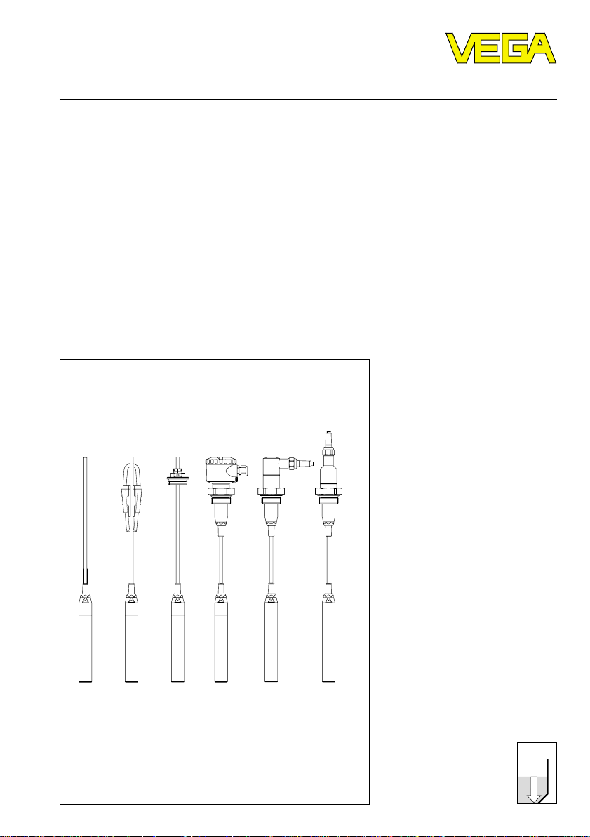
1.2 Types and versions
Suspension pressure transmitter D76
with CERTEC
Features
- Compact instrument with integrated electronics
- Diameter of the transmitter 32 mm
- Connection housing in protection IP 66/IP
67/IP 68
- Electronics as two-wire system 4 … 20 mA
- Power supply 12 … 36 V
- Adjustment/indication in separate housing
VEGADIS 12 possible
Applications
- Level and gauge measurements in water
sewage water, flumes, basins, deep wells,
vessels and tanks
Suspension pressure transmitter D77
with Duratherm 600 diaphragm
Features
- Compact instrument with integrated electronics
- Diameter of the transmitter 32 mm
- Connection housing in protection IP 66/
IP 67/IP 68
- Electronics as two-wire system 4 … 20 mA
- Power supply 12 … 36 V
- Adjustment/indication in separate housing
VEGADIS 12 possible
Applications
- Level and gauge measurements in water/
sewage water, flumes, basins, deep wells,
vessels and tanks
®
4 Pressure transmitters D76 and D77
Page 5
Product description
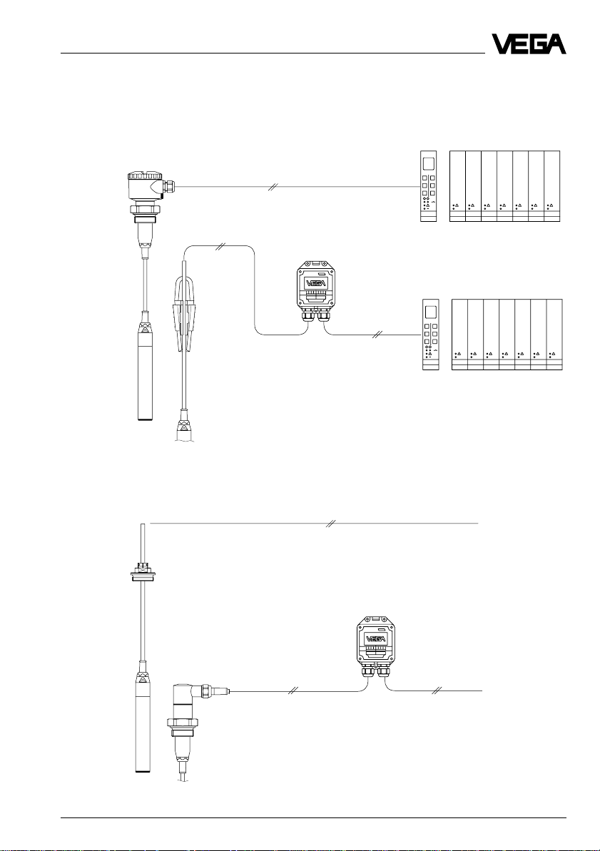
1.3 Electronics version without adjustment
Electronics version A:
Pressure transmitter for connection to VEGA signal conditioning instruments
VEGAMET
VEGABOX 01
VEGALOG
Electronics version C:
Pressure transmitter 4 … 20 mA
VEGABOX 01
VEGAMET
VEGALOG
PLC/DCS
PLC/DCS
Pressure transmitters D76 and D77 5
Page 6
Product description
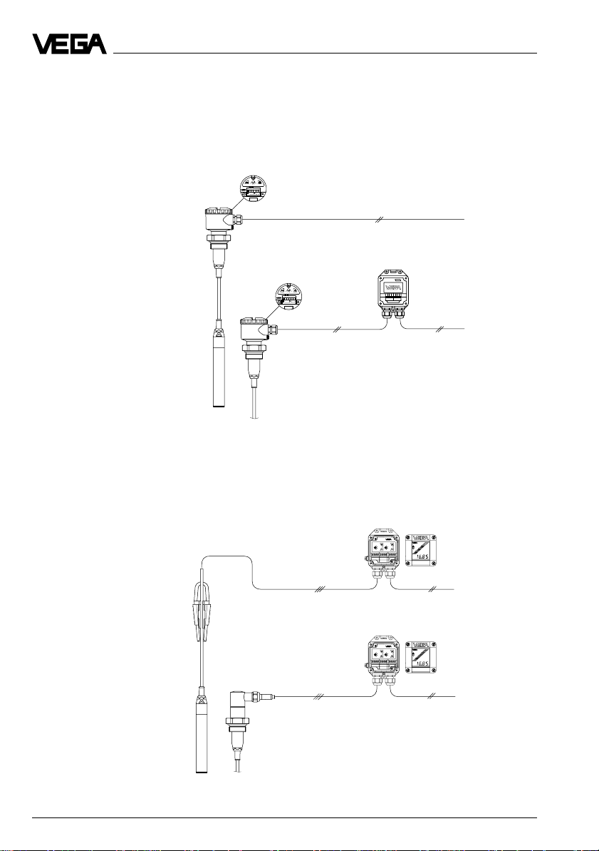
1.4 Electronics version with integrated adjustment in connection housing
Electronics version D:
Pressure transmitter 4 … 20 mA adjustable
Adjustment in connection housing
S
Op
Zt
i
43215
+
-
4...20mA
12V...36V DC
Bedieneinsatz
operating unit
PLC/DCS
VEGABOX 01
S
Op
Zt
i
43215
+
-
4...20mA
12V...36V DC
Bedieneinsatz
operating unit
PLC/DCS
1.5 Electronics for connection to VEGADIS 12
Electronics version E:
Pressure transmitter 4 … 20 mA
Adjustment in VEGADIS 12
6 Pressure transmitters D76 and D77
VEGADIS 12
DISPLAY
TRANSMITTER
DISPLAY
TRANSMITTER
OPERATE
OPERATE
OPERATE
OPERATE
ti
ti
ZERO
ZERO
END
END
ZERO
ZERO
POINT
SPAN
POINT
SPAN
VEGADIS 12
DISPLAY
DISPLAY
TRANSMITTER
TRANSMITTER
OPERATE
OPERATE
OPERATE
OPERATE
ti
ti
ZERO
ZERO
END
END
ZERO
ZERO
POINT
POINT
SPAN
SPAN
PLC/DCS
PLC/DCS
Page 7
12
300
600
900
18 24 30 36
Product description
2 Technical data
2.1 Data
Supply and signal current circuit (analogue transmission, 4 … 20 mA)
Power supply 12 … 36 V DC
Residual ripple of the power supply no influence at U
Output signal
- terminal insert analogue transmission (not standardised)
4 … 20 mA
- adjustment insert 4 … 20 mA (adjustable)
Current limitation approx. 22 mA
Fault signal 22 mA
Integration time 0 … 10 s (adjustment time from 10 % … 90 %
of measuring range final value)
Average delay time 85 ms
Connection cable 2-wire
Max. permissible load depending on power supply
see following load diagram
Load in W
< 100 mV
SS
Integrated overvoltage protection (option)
Pressure transmitters D76 and D77 7
Nominal d.c. spark-over voltage
- protective diode 40 V
- gas separator 650 V
Nominal discharge current
- gas separator 20 kA
Supply voltage
in V
Page 8
Product description
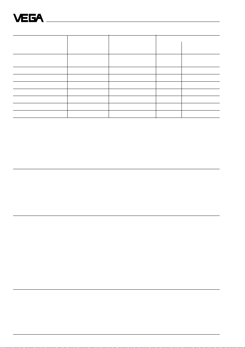
Measuring ranges
Nominal meas. range Gauge pressure Low pressure Pressure transmitters
resistance resistance D76 D77
D76 / D77
Gauge pressure
0 … 0.1 bar 10 bar / – -0.1 bar • –
0 … 0.2 bar 15 bar / – -0.2 bar • –
0 … 0.4 bar 20 bar / 10 bar -0.4 bar • •
0 … 1.0 bar 25 bar / 25 bar -1.0 bar • •
0 … 2.5 bar 35 bar / 25 bar -1.0 bar • •
0 … 5.0 bar 45 bar / 25 bar -1.0 bar • •
0 … 10.0 bar 60 bar / 25 bar -1.0 bar • •
0 … 20.0 bar 90 bar / 25 bar -1.0 bar • •
Zero -20 % … +95 % of nominal measuring range
adjustable
Span 3.3 % … 120 % of nominal measuring range
adjustable
Recommended turn down with
accuracy class 0.25 up to 1 : 5
Adjustment elements
Pressure transmitters
- terminal insert without adjustment elements
- adjustment insert 2 keys, 1 rotary switch
Measuring accuracy (similar to DIN 16 086, DIN V 19 259-1 and IEC 770)
Deviation
Reference conditions acc. to IEC 770
- temperature 15°C … 35°C
- moisture 45 % … 75 %
- air pressure 860 mbar … 1060 mbar
Determination of characteristics limit point adjustment acc. to DIN 16 086
Characteristics linear
Deviation in characteristics
Hysteresis
Repeatability
1)
1)
Influence of the ambient temperature in general
Average temperature coefficient
of the zero signal
1) 2)
1)
< 0.25 % with accuracy class 0.25
< 0.02 % ceramic measuring cell
< 0.05 % metallic measuring cell
< 0.02 % ceramic measuring cell
< 0.05 % metallic measuring cell
< 0.15 %/10 K with accuracy class 0.25
1)
Relating to the nominal measuring range.
2)
In the compensated temperature range of 0°C … +80°C, reference temperature 20°C.
8 Pressure transmitters D76 and D77
Page 9

Product description
Long-term stability
Longterm drift of the zero signal
1)
- D76 (ceramic measuring cell) < 0.1 %/year
- D77 (metallic measuring cell) < 0.25 %/year
Other actuating variables
Calibration position upright, diaphragm points downwards
Influence of the mounting location
- ceramic measuring cell < 0.2 mbar
- metallic measuring cell < 5.0 mbar
Vibration resistance mechanical vibrations with 4 g and
5 … 100 Hz, tested acc. to the regulations of
German Lloyd, GL regulation 2
Operating conditions
Ambient conditions
Ambient temperature -40°C … +60°C
Storage and transport temperature -40°C … +60°C
Product temperature -40°C … +60°C
Protective measures
Transmitter IP 68
Housing
2)
IP 66 or IP 67, IP 68 (by fixed connected
PE-cable, cable length min. 5 m)
General data
Connection cables
Cable entry
- in connection housing 2 x M20 x 1.5 (for cable ø 5 … 9 mm)
- external housing VEGABOX 01 2 x M20 x 1.5 (for cable ø 5 … 9 mm)
Screw terminals
- terminal, adjustment insert for conductor cross-sections up to 2.5 mm
- external connection housing
VEGABOX 01 for conductor cross-sections up to 2.5 mm
1)
Acc. to IEC 770, item 6.1.2 relating to the nominal measuring range.
2)
Use of suitable seal in the PG is necessary for maintaining the housing protection IP 65 or IP 67.
Pressure transmitters D76 and D77 9
2
2
Page 10

Product description
Materials, wetted parts
Pressure transmitters D76
- transmitter stainless steel 1.4571
- diaphragm ceramic (99.9 % Oxideceramic)
- suspension cable PE-LD
cable bushing CSM
- measuring cell seal Viton
Pressure transmitters D77
- transmitter stainless steel 1.4571
- diaphragm Duratherm 600
- suspension cable PE-LD
cable bushing CSM
Materials, non-wetted parts
Pressure transmitters D76, D77
- housing Alu (sea-water resistant) and powder-
- straining clamp galvanised steel
- closing screw stainless steel 1.4305
Weight
Basic weight without housing
- D76 approx. 0.7 kg
- D77 approx. 0.7 kg
VEGABOX 01 approx. 400 g
Suspension cable approx. 0.1 kg/m
coated, stainless steel 1.4571
2.2 Approvals and certificates
Ex approvals
When using pressure transmitters in Ex areas, the instruments must be suitable and approved for these explosion zones and application areas. Special type approvals are available
for the use on ships. The suitability is checked by approval authorities and certified by approval documents. Please note the attached approval documents when using a sensor in Ex
areas.
Pressure transmitters D7. Ex are approved for Ex Zone 1.
CE conformity
Pressure transmitters D76 and D77 meet the protective regulations of EMC (89/336/EWG)
and NSR (73/23/EWG). Conformity has been judged acc. to the following standards:
EMC Emission EN 50 081 - 1: 1992
NSR EN 61 010: 1993
NAMUR regulations
Full compliance with the NAMUR regulations NE 21, May 1993.
10 Pressure transmitters D76 and D77
Susceptibility EN 50 082 - 2: 1995
Page 11

Product description
2.3 Dimensions
C1
52
1
1
R
49
175
41
14
25
X4 A4 V4
ø 8
SW 30
G 1½ A
A1, A2, B1, B2 C3 D3
66
ø 76
77
ø 41,6 ø 41,6 ø 41,6
39
20
77
SW 60 SW 60
G 1½ A
100
39
20
G4 N4
139
1½" NPT
D77: 247
D76: 230
ø 32
D77: 267
D76: 250
ø 32
D77: 285
D76: 268
ø 36
XVP
Pressure transmitters D76 and D77 11
Page 12

VEGABOX 01 (connection housing with breather facility)
85
108
118
135
38 72
ø 5
Zum Anschluss an
For connection to
Druckmessumformer mit
pressure transmitters with
analogem Ausgangsignal
analog output
-
+
-
TRANSMITTER
VEGABOX 01
+
M20 x 1.5 (cable ø 5 … 9 mm)
with optional protective cover
Product description
72100
139
12 Pressure transmitters D76 and D77
130
Page 13

Mounting
3 Mounting
3.1 Mounting instructions
Cable entry
The pressure transmitters can be mounted in
any position. Cable entries must point downwards to avoid moisture ingress. For this
purpose, the housing can be rotated by 330°
in relation to the mounting part.
A seal, appropriate for connection, must be
used for mounting. This seal is either supplied with the pressure transmitter or must be
provided by the customer.
3.2 Compensation of the atmospheric pressure
On instruments for gauge pressure measurement, the atmospheric pressure is compensated in different ways, depending on the
pressure transmitter version.
Pressure transmitters with housing
- via an integrated breather facility below the
cable entry (PTFE insert
IP 66
- via the capillary tubes of the special ca-
2)
ble
, used with the pressure transmitter,
protection IP 67
Pressure transmitters with direct cable
outlet
- via the capillary tubes of the connected
special cable
2)
, protection IP 68
External housing VEGABOX 01
We recommend leading the special cable to
the external housing VEGABOX 01 (accessory) and carrying out the pressure compensation via the integrated breather facility.
Keep the following instructions in mind:
- the same atmospheric pressure as on the
pressure transmitter must also be present
on the external housing VEGABOX 01
- the pressure compensation must be made
in a dry environment
- for vertical wall mounting, the cable entries
must point downwards to avoid moisture
ingress.
1)
), protection
1)
Air permeable and moisture-blocking
2)
Cable length 5 m (supplied cable)
Pressure transmitters D76 and D77 13
Page 14

4 Electrical connection
Electrical connection
4.1 Connection instructions
The electronics in the pressure transmitter
requires a supply voltage of 12 … 36 V DC. It
is provided by two-wire technology, i.e. supply voltage and measuring signal are transmitted via the same two-wire connection
cable.
The supply voltage is provided via a power
supply unit, e.g.:
- power supply unit VEGASTAB 690
- processing unit with integrated DC current
source (e.g. active PLC input)
- VEGAMET, VEGALOG or VEGADIS 371
Make sure that the supply voltage is reliably
separated from the mains circuits acc. to DIN
VDE 0106, part 101. VEGA instruments meet
this requirement and protection class III is
therefore ensured.
The terminal voltage on the transmitter depends on the following factors:
- output voltage U
under nominal load.
- electrical resistance of the connected instruments in the circuit.
Note the following instructions for electrical
connection:
- Connection must be made according to the
specific installation standards (e.g. in Germany acc. to the VDE regulations).
- Terminal voltage must not exceed 36 V, to
avoid damage to the electronics.
- Electrical connection must have a preventative measure against inadvertent
polarity reversal.
- The pressure transmitter can be connected
with standard two-wire cable.
- Screened cable is recommended, if strong
electromagnetic interference is to be expected. The screening must be grounded
at both ends. Please note the installation
regulations for mounting in Ex areas.
of the power supply
H
- If overvoltages are expected, we recommend pressure transmitters with integrated
overvoltage arrester or the installation of
VEGA overvoltage arresters.
- In the cable connection, a seal must be
used which fits the cable.
Safety information for Ex applications
As a rule, do all work in the complete absence of line voltage. Always switch off the
power supply before you carry out connecting work on the sensors. Protect yourself and
the instruments.
Qualified personnel
Instruments which are operated in Ex areas,
must be connected only by qualified personnel. The qualified personnel must observe
and understand the installation regulations
and the attached type approval and conformity certificates.
In hazardous areas, the required regulations
and conformity and type approval certificates
of the sensors and separators or safety
barriers must be observed (e.g. DIN VDE
0165). Sensors used in Ex areas must be
operated only on intrinsically safe circuits.
The permissible electrical values are stated in
the type approval or conformity certificate.
Intrinsically safe circuits with more than one
active instrument (delivering electrical en-
14 Pressure transmitters D76 and D77
Page 15

Electrical connection
ergy) must not connected in series. The
special installation regulations (DIN VDE
0165) must be observed.
Pressure transmitters in certain versions are
equipped with a warning label, informing of
measures to be taken to avoid electrostatic
discharge. Keep the contents of the warning
label in mind.
Connection cable
Make sure that the connection cable is specified for the expected operating temperatures
in your systems. The cable must have an
outer diameter of 5 … 9 mm. Otherwise the
seal effect of the cable connection will not be
ensured.
Cables for intrinsically safe circuits must be
marked with a blue colour and must not be
used for other circuits.
Direct cable outlet
4.2 Terminal assignment
Screen
Breather capillaries
Suspension
cable
12 … 36 V DC
br
+
for supply or to the process-
bl
ing system (4 … 20 mA)
-
ge
only used in conjunction with
VEGADIS 12, if not used,
connect to minus
Electronics version A
5 … 19 mA output signal for connection to
VEGA signal conditioning instruments
Zum Anschluss an
For connection to
VEGA-Auswertgeräte
VEGA-signal conditioning instruments
51234
-
+
Klemmeinsatz
terminal
-
Control instrument
(5 … 19 mA measurement)
+
Supply or for evaluation
+
of VEGAMET signal
conditioning instrument
-
12 … 36 V DC
Electronics version C
4 … 20 mA output signal
4-20mA
-
+
4...20mA
12V...36V DC
Klemmeinsatz
terminal
51234
+
Control instrument
4 … 20 mA
-
-
Power supply
12 … 36 V DC
+
Electronics version D
4 … 20 mA output signal with integrated
adjustment
S
Zt
+
-
4...20mA
12V...36V DC
Bedieneinsatz
operating unit
Op
i
43215
-
Control instrument
4 … 20 mA
+
-
Power supply
12 … 36 V DC
+
Electronics version E
4 … 20 mA output signal with operatability
from VEGADIS 12
Zum Anschluss an
For connetction to
VEGADIS 12
51234
-
+
12V...36V DC
Klemmeinsatz
terminal
Terminal assignment
Ground, cable screen
1 Power supply [+]
2 Power supply [–]
3 Control instrument [–] / VEGADIS 12
4 not assigned, connect via wire bridge
5 not assigned, connect via wire bridge
ge
for indicating instru-
-
ment VEGADIS 12
+
Pressure transmitters D76 and D77 15
Page 16

4.3 Connection to VEGABOX 01
Pressure transmitters with direct
cable outlet
Screen
Pressure transmitters with
terminal insert in housing
Breather capillaries
Suspension cable
br
+
bl
-
ge
Zum Anschluss an
For connection to
Druckmessumformer mit
pressure transmitters with
analogem Ausgangssignal
analog output
1
231011 12
TRANSMITTER
VEGABOX 01
-
+
-
+
Electrical connection
For supply or to the
+
processing system
-
(4 … 20 mA,
12 … 36 V DC)
4-20mA
-
+
4...20mA
12V...36V DC
Klemmeinsatz
terminal
+
-
51234
+
Control instrument
-
(4 … 20 mA measurement)
4.4 Connection examples
The following connection examples are valid for direct connection to the terminals of the pressure transmitter. When using the external connection housing, the connection is made to the
respective terminals of the housing.
Powered by a power supply unit
Processing via an indicating instrument.
Ammeter for local control
analogue / digital indicat-
+ - -
1 2 3
Pressure transmitter
terminals
U
K
ing instrument
U
4 … 20 mA
External energy source
A
-
U
H
~
+
16 Pressure transmitters D76 and D77
Page 17

Electrical connection
Powered by a VEGA signal conditioning instrument
Standard wiring for nonstandardized output.
Ammeter for local control
+ - -
1 2 3
Pressure transmitter
terminals
U
K
Analogue transmission, not
standardised
0/4 … 20 mA
U
H
DISBUS
!
Powered by a PLC with active input circuit
Processing via PLC.
Ammeter for local control
+ - -
Pressure transmitter
terminals
PLC
1 2 3
U
K
4 … 20 mA
U
-
H
+
Note:
An ammeter for local control of the output current can be connected to terminals 1 and 3. This
measurement can be carried out during operation, without interrupting the supply cable.
Pressure transmitters D76 and D77 17
Page 18

5 Setup
Setup
5.1 Sensor without adjustment
Sensors with electronics version A and C
have no adjustment possibility and are permanently adjusted to the stated measuring
range.
5.2 Adjustment with the adjustment insert in the sensor
Sensors with electronics version D are
equipped with a 2-key adjustment insert.
1
2
3
S
Zti
+
Op
-
Procedure
• Select the required function with the rotary
switch.
• With the "+“ and "–“ key you modify the
signal current to the required values or set
the suitable integration time.
• Then, you set the rotary switch to position
"OPERATE“. The set values are transferred
to the EEPROM memory and remain there
even in case of voltage failure.
Adjustment
For adjustment of zero and span, first of all
connect terminals 1 and 3 to an ammeter. The
measured value is identical to the output
current.
First of all adjust zero (empty vessel)
• Set the rotary switch to "zero“. Empty the
vessel.
• Adjust a current of 4 mA by pushing the "+“
and "–“ keys.
The adjustment range of zero can be between -20 % and +95 % of the nominal measuring range.
12345
+-
4...20mA
12...36 V DC
Then adjust span (full vessel)
• Set the rotary switch to "span“. Completely
fill the vessel.
• Adjust a current of 20 mA by pushing the
"+“ and "–“ keys.
The adjustment range of span can be between 3.3 % and 120 % of the nominal meas-
1 Reduce value
2 Rotary switch
3 Increase value
uring range.
With the rotary switch you can select four
switch positions:
S - Span (pressure measuring range)
Z - Zero (zero adjustment)
ti - Time (integration time)
Op - Operate (operating status)
18 Pressure transmitters D76 and D77
Page 19

Setup
Adjustment information:
- A modification of zero does not influence
the adjusted span.
- It is also possible to adjust currents for
partial fillings, e.g. 8 mA for 25 % and
16 mA for 75 %. Then the electronics automatically calculates the current values for
0 % and 100 % (only possible with a difference ³ 3.3 %).
- If the current values react to the key pressing with a time delay, there can be two
reasons:
- the last adjustment was carried out with a
level deviating considerably from the
actual level.
Integration time
For damping level fluctuations, an integration
time ti of 0 … 10 sec. can be adjusted.
Adjust integration time
• Set rotary switch to "ti“.
• By pressing the "-“ key 10 times make sure
that the integration time is set to 0 sec.
• Per 1 sec. requested integration time, the
"+“ key has to be pushed once.
The integration time is the time required by
the current output signal to reach 90 % of the
actual level after a sudden change of the
level.
Pressure transmitters D76 and D77 19
Page 20

6 Diagnostics
Diagnostics
6.1 Maintenance
Pressure transmitters D76 and D77 are maintenance-free.
6.2 Failure rectification
Due to continuous self-monitoring, series D70
pressure transmitters offer maximum reliability. However, should failures occur, check the
following before removing the pressure
transmitter:
- the atmospheric pressure compensation,
- the electrical connections.
Checking atmospheric pressure compensation
First open the cover of the housing, in which
the atmospheric breather facility is located.
The displayed measured value must not
change. However, if the displayed value
changes, compensation of the atmospheric
pressure is not ensured, which will lead to
distortion of the measured value. Therefore
check:
- the breather facility on the housing
- VEGADIS 12 or VEGABOX 01
- the capillary tubes in the special cable.
Note:
There must always be the same atmospheric
pressure on the breather facility as in the
open vessel.
Checking electrical connections
Pressure transmitter
terminals
1 2 3
mA
Current
Voltage Current
V
mA
External
energy source
-
~
+
Voltage
- the terminal voltage on the pressure transmitters must be at least 12 V DC
Current
Current value Condition
3.8 … 20.5 mA standard range for the output
0 mA signal cable interrupted
< 3.6 mA sensor electronics or pressure
22 mA sensor electronics or pressure
Note for Ex applications
Deviating from above regulation, here terminals 1 and 3 (on VEGADIS 12 terminals 10
and 12) are used only for brief connection to
a certified active, floating measuring instrument (max. value: 470 mW) or an individual
passive, floating ammeter. When connecting,
the regulations for wiring of intrinsically safe
circuits (measuring instrument, supply and
signal circuit) have to be observed.
current
sensor element defective
sensor element defective
20 Pressure transmitters D76 and D77
Page 21

Instrument modification
7 Instrument modification
7.1 Retrofitting of adjustment insert
Such a retrofitting can be necessary, e.g. if
you want to adapt a pressure transmitter to
different measurement conditions.
Remove existing terminal insert
1 Disconnect pressure transmitter from
power supply.
2 Unscrew cover of the connection hous-
ing.
3 Remove cover.
4 Pull out connection cables from the termi-
nal insert.
5 Loosen the three screws on the terminal
insert.
6 Remove terminal insert and plug connec-
tion (carefully bend the locking clip to-
ward the centre of the housing).
Fitting new adjustment insert
7 Push plug connection into the adjustment
insert (must snap in).
8 Place adjustment insert in the housing
and fasten with three screws.
9 Reconnect the connection cables to the
terminals.
10 Fasten the cover.
11 Reconnect the pressure transmitter to
power supply.
For setup of pressure transmitters, see
chapter "5 Setup“.
Pressure transmitters D76 and D77 21
Page 22

Notes
22 Pressure transmitters D76 and D77
Page 23

Notes
Pressure transmitters D76 and D77 23
Page 24

VEGA Grieshaber KG
Am Hohenstein 113
D-77761 Schiltach
Phone (0 78 36) 50 - 0
Fax (0 78 36) 50 - 201
e-mail info@vega-g.de
ISO 9001
The statements on types, application, use and operating conditions of
the sensors and processing systems correspond to the latest information at the time of printing.
Technical data subject to alterations
2.22 064 / March 2000
 Loading...