

Page 1

C-Soft
Software Console
Administrator’s Guide
version 4.000 and later
LIT000082000 Rev B April 2007
Page 2

PROPRIETARY NOTICE
PHONE NUMBERS
The product information and design disclosed herein were originated by
and are the property of Telex Communications, Inc. Telex reserves all
patent, proprietary design, manufacturing, reproduction, use and sales
rights thereto, and to any article disclosed therein, except to the extent
rights are expressly granted to others.
COPYRIGHT NOTICE
Copyright 2007 by Telex Communications, Inc. All rights reserved.
Reproduction, in whole or in part, without prior written permission from
Telex is prohibited.
WARRANTY NOTICE (LIMITED)
All Telex manufactured signaling products are guaranteed against
malfunction due to defects in materials and workmanship for three (3)
years, beginning at the original date of purchase.If such a malfunction
occurs, the product will be repaired or replaced (at our option) without
charge during the three (3) year period, if delivered to the Telex factory.
Warranty does not extend to damage due to improper repairs, finish or
appearance items, or malfunction due to abuse or operation under other
than the specified conditions, nor does it extend to incidental or
consequential damages. Some states do not allow the exclusion or
limitation of incidental or consequential damages. Some states do not
allow the exclusion or limitation of incidental or consequential damages,
so the above limitation may not apply to you. This warranty gives the
customer specific legal rights, and there may be other rights which vary
from state to state.
Sales:
Phone ...................................................................(800) 752-7560
Fax........................................................................(402) 467-3279
E-mail.................................................................vega@telex.com
Customer Service Repair: .................................................(800) 553-5992
Technical Support:
Phone ...................................................................(800) 898-6723
E-mail ............................................ acttechsupport@us.telex.com
Web ...................................................................................www.telex.com
CLAIMS
No liability will be accepted for damages directly or indirectly arising
from the use of our materials or from any other causes. Our liability shall
be expressly limited to replacement or repair of defective materials.
FACTORY SERVICE CENTER
Factory Service Center
Telex Communications, Inc.
Radio Dispatch Products
8601 East Cornhusker Highway
Lincoln, Nebraska, 68507
Page 3

Table
of
Contents
DESCRIPTION ................................................. 7
Overview .................................................................7
COMPUTER SYSTEM REQUIREMENTS .............................7
C-S
OFT APPLICATION SOFTWARE ..................................7
CSoftDesigner Program ...........................................7
CSoftRuntime Program ............................................8
INSTALLATION AND SETUP ........................ 9
Install the Software .................................................9
License Dongle Driver Installation ......................10
Initial Volume Control Settings ............................11
PLAYBACK VOLUMES ...................................................11
R
ECORDING VOLUMES ................................................11
COMMUNICATIONS SYSTEM DESIGN .... 13
Network Requirements ..........................................13
BANDWIDTH ................................................................13
M
ULTICAST .................................................................13
NTERNET GROUP MANAGEMENT PROTOCOL (IGMP) 14
I
ETWORK PERFORMANCE ...........................................14
N
CSOFTDESIGNER PROGRAM .................... 15
Starting the CSoftDesigner Program ...................15
CSoftDesigner Window .........................................15
TITLE BAR ...................................................................16
M
ENU BAR ..................................................................16
OOLBAR ....................................................................16
T
ONSOLE WINDOW .....................................................18
C
S
TATUS BAR ................................................................18
Interface Element Manipulation ...........................19
File Menu ..............................................................22
OPEN ..........................................................................22
S
AVE ...........................................................................22
XIT ............................................................................23
E
Edit Menu .............................................................24
SETUP PER LINE PARAMETERS ....................................24
Line Number Field .................................................25
Line Type Drop-down Menu ..................................25
Line Name Field .....................................................25
RX and TX Multicast Address Fields .....................25
RX and TX Port Fields ...........................................25
Base Radio IP Field ...............................................25
TTL (Time To Live) Field .......................................26
Packet Delay Field .................................................26
TxMon Enable Check Box ......................................26
Scannable Check Box .............................................26
Echo Packets Enable Check Box ............................26
Backup IP Setup Button ..........................................27
B
ACKUP IP PARAMETERS WINDOW .............................28
RX Multicast Address and Port Fields ................28
TX Multicast Address and Port Fields ................28
Base Radio IP Field ............................................28
OK Button ............................................................28
Cancel Button ......................................................28
Freqs Button ...........................................................28
Per Line Frequency Setup Window 28
Enable Check Box ...............................................29
Frequency Name Field ........................................29
Pair Mode Setup Check Boxes ............................29
RX Block Lines Display Box ................................30
Close Button ........................................................30
Signal Setup Button ................................................30
S
IGNALING SETUP PARAMETERS ..................................30
Per Line Console ID field .......................................31
Auto Ack Setup Group Box .....................................31
Auto Ack Type drop down menu ..........................31
Auto Ack Delay field ............................................31
Signaling Delays Group Box ..................................31
Initial Delay field ................................................31
End Delay field ....................................................31
Global Group Box ..................................................31
Set All Lines check box ........................................31
Single Tone Auto Ack Setup Group Box .................31
Frequency field ....................................................31
Duration field ......................................................32
Level field ............................................................32
Signaling Setup Group Box ....................................32
Signaling Type drop-down menu .........................32
Digit Duration field .............................................32
Interdigit Duration field ......................................32
Page 4

Table
of
Contents
Pause Duration field ...........................................32
Preamble Duration field .....................................32
Level field ............................................................33
Twist Level field ..................................................33
Group Digit field .................................................33
Repeat Digit ........................................................33
Call Setup Group Box ............................................33
Auto Ack field ......................................................33
Emerg Resolved field ...........................................33
PTT BOT field .....................................................34
PTT EOT field .....................................................34
Call 1 through Call 10 Format field ...................34
Call 1 through Call 10 Label field ......................35
A
UTOFILL LINE PROPERTIES .......................................36
OK Button ...............................................................36
Cancel Button .........................................................36
S
ETUP GLOBAL PARAMETERS ......................................37
DTMF Setup Group Box ........................................37
Flywheel Field .....................................................37
Level Field ...........................................................38
Supervisor Group Box ............................................38
Timeout Field ......................................................38
HB3 Serial Port Drop-down menu .........................38
Local Console IP Address Fields ...........................38
IP Address or Name of License Server Field .........38
Window Controls Check Boxes ..............................39
IP Interface Spin Box .............................................39
Ring Sound Drop-down Menu ................................39
Background Color ..................................................39
Logo Fields .............................................................39
Bitmap Filename Field ........................................39
Position Drop-down Menu ..................................39
Audio Routing and Muting Check Boxes ...............40
Kill Lines on Crosspatch Check Box ......................40
Enable Sticky ANI Check Box ................................40
Enable Residue ANI Check Box .............................40
Allow Freq Update Anytime Check Box .................40
Disable Local iDEN Tones Check Box ..................40
Radio Ping Interval Field .......................................40
RX Block Delay Field .............................................41
Tones/DTMF Sidetone Level Field ........................41
MIC AGC Enabled Check Box ..............................41
Target Level Field .............................................. 41
Min Active Field .................................................41
Phone Ring Multicast and Port Fields .................. 41
NEO-10 Update Multicast and Port Fields ........... 41
Positional Recording Group Box ...........................41
OK Button ..............................................................42
Cancel Button ........................................................42
S
ETUP GLOBAL CALL PARAMETERS ............................42
Window Titles Group Box ......................................42
Active Emergency Field ......................................42
Emergency History Field .................................... 43
Per Line Call History Field ................................ 43
Call List Field ..................................................... 43
Manual Call List Field ....................................... 43
Status List Field ..................................................43
Call Options Group Box ........................................ 43
Call-to-Console Color Field ............................... 43
Change Color Button .......................................... 43
Date Format Drop Down Menu ......................... 43
Display All Calls Check Box ..............................44
Per Line Call History Window Lines Field ........44
Per Line Call History Font Size Field ................ 44
Emergency Call History Window Lines Field .... 44
Emergency Call History Font Size Field ............44
Active Emergency Font Size Field ......................44
Call List Font Size Field .....................................44
Status List Font Size Field ..................................44
Labels on Buttons Group Box ................................ 44
ACK Field ...........................................................44
Resolved Field ....................................................44
Done Field ..........................................................44
Set Status Field ...................................................45
Clear Field ..........................................................45
Cancel Field .......................................................45
Backspace Field .................................................. 45
Digit A-F Fields ..................................................45
Labels on Column Headings and
Static Text Group Box ...........................................45
Date Field ...........................................................45
Time Field ...........................................................45
Page 5

Table
of
Contents
Channel Field ......................................................45
Freq Field ...........................................................45
Status Field .........................................................45
User ID Field ......................................................45
Calling ID Field ..................................................46
Status ID Field ....................................................46
Alias Field ...........................................................46
ID Type Field ......................................................46
OK Button ..............................................................46
Cancel Button .........................................................46
Defaults Button ......................................................46
P
AGER SETUP .............................................................47
Pager Number Field ..............................................47
Setup Button ...........................................................47
Send Sequentially Check box .................................47
Correct Low Freq Tone Levels
(Flatten Levels) Check box ....................................48
OK Button ..............................................................48
2 T
ONE 100 PAGE SETUP WINDOW .............................48
Page Name Field ....................................................48
Page Level Field ....................................................48
Initial Delay Field ..................................................49
Tone 1 Group and Tone 2 Group Fields ................49
Tone 1 Time Field ..................................................49
Gap Duration Field ................................................49
Tone 2 Time Field ..................................................49
Group Tone Time Field ..........................................49
Enable Diagonal Check Box ..................................49
Diag Tone Freq Field ............................................49
Diag Location Check Box ......................................49
OK Button ..............................................................49
Cancel Button .........................................................49
2 T
ONE 1000 SETUP WINDOW .....................................51
Page Name Field ....................................................51
Page Level Field ....................................................51
Initial Delay Field ..................................................51
Tone Plan Number Field ........................................51
Tone 1 Time Field ..................................................52
Gap Duration Field ................................................52
Tone 2 Time Field ..................................................52
Group Tone Time Field ..........................................52
Enable Diagonal Check Box ..................................52
Diag Tone Freq Field .............................................52
Diag Location Check Box ......................................52
OK Button ...............................................................53
Cancel Button .........................................................53
DTMF P
Page Name Field ....................................................54
Page Level Field .....................................................54
Initial Delay Field ..................................................54
DTMF On Time Field .............................................54
DTMF OFF Time Field ..........................................54
DTMF Digits Field .................................................54
OK Button ...............................................................54
Cancel Button .........................................................55
E
DIT USER ID LIST .....................................................55
Name Field .............................................................55
Cancel Button .........................................................55
E
DIT USER ID LIST .....................................................55
Name Field .............................................................55
User ID Field .........................................................56
Load File Button .....................................................56
Save File Button .....................................................56
Close Button ...........................................................56
E
DIT GROUP ID LIST ..................................................57
Group Field ............................................................57
Group ID Field .......................................................57
Set Color Check Box ..............................................57
Set Color Button .....................................................58
Load File Button .....................................................58
Save File Button .....................................................58
Uncheck All Button .................................................58
Reset Colors ...........................................................58
Close Button ...........................................................58
E
DIT STATUS MESSAGE ID LIST ..................................58
Status Message Field ..............................................59
Status ID Field .......................................................59
Set Color Check Box ..............................................59
Set Color Button .....................................................60
Load File Button .....................................................60
Save File Button .....................................................60
Uncheck All Button .................................................60
AGING SETUP WINDOW .................................54
Page 6

Table
of
Contents
Reset Colors ...........................................................60
Close Button ...........................................................60
CREEN DESIGN EDIT COMMANDS ..............................61
S
Insert Menu .......................................................... 62
UI Element Setup window ......................................62
T
YPE TAB ....................................................................64
UI Element Function Drop-down Menu ................64
Line to Associate Function With
Drop-down Menu ...................................................64
OK Button ...............................................................64
OLORS TAB ...............................................................65
C
Button Up and Button Down Group Boxes ............65
Button Drop-down Menu .....................................65
Text Drop-down Menu ........................................65
Button Bitmaps Fields .........................................65
Up Position and Down Position Bitmap Fields ..66
Button Up Text Field ..............................................66
Button Down Text Field .........................................66
Border Color Drop-down Menu .............................66
Set Font Button .......................................................66
OK Button ...............................................................66
A
DD UI BUTTON .........................................................67
CTIVE EMERGENCY WINDOW ....................................67
A
LERT .........................................................................68
A
Tone Type Fields ....................................................68
Low Frequency Field .............................................69
Low/On Duration Field ..........................................69
Hi Frequency Field ................................................69
Hi/Off Duration Field ............................................69
Tone Level Field .....................................................69
A
UTO-DIAL STRING ENTRY ..........................................70
Enter Dial String Field ...........................................70
ACKUP LINE ..............................................................71
B
Allow User to Switch
Primary/Backup Check Box ...................................71
P
ER LINE CALL HISTORY 72
Call List Window ....................................................73
C
ROSSPATCH ...............................................................74
ROSSPATCH BLOCK ...................................................75
C
C
ROSSPATCH CLEAR ...................................................75
ROSSPATCH PROGRAMMED .......................................75
C
Select Lines for Group Field ..................................76
Group Patch Number Drop-down Menu ............... 76
Autostart Crosspatch Check Box ...........................76
ROSSPATCH PTT ...................................................... 77
C
DTMF D
DTMF Digit Drop-down Menu .............................. 78
E
MERGENCY ACK ....................................................... 79
MERGENCY HISTORY WINDOW ..................................80
E
MERGENCY RESOLVE ................................................ 80
E
E
NCRYPTION ...............................................................80
REQUENCY CHANGE ................................................. 81
F
Select PTT Frequency Drop-down Menu .............. 82
G
ROUP PROGRAMMED ................................................ 83
Select Lines for Group Field ..................................83
ROUP SELECT ..........................................................84
G
G
ROUP SELECT LIMITED ............................................ 84
Max Number of Simultaneous
Selected Lines Field ............................................... 84
NPUT INDICATION ...................................................... 85
I
Input Source and Polarity Radio Buttons ..............85
Annunciation of Input Change Group Box ............ 86
Input Destination Radio Buttons ...........................86
NEO Settings Group Box .......................................86
I
NSTANT RECALL .........................................................87
Audio Playback Start Field .................................... 87
Audio Source Drop-down Menu ............................87
I
NTERCOM ..................................................................88
NTERCOM-PER LINE .................................................. 88
I
Manual Call List Window ...................................... 89
M
ARKER TONE ............................................................90
Tone Type Radio Buttons ....................................... 90
Low Frequency Field .............................................90
Low/On Duration Field .........................................90
Hi Frequency Field ................................................ 91
Hi/Off Duration Field ............................................91
Tone Level Field .................................................... 91
Keyup Duration Field ............................................91
Time Between Tones Field ..................................... 91
IGIT ............................................................. 78
Active High Check Box ....................................... 86
IP Field ...............................................................86
Input Drop-down Menu ...................................... 86
Page 7

Table
of
Contents
MONITOR ....................................................................91
M
UTE GROUP .............................................................92
UTE MAIN ................................................................93
M
UTE - PER LINE .......................................................93
M
Mute Time Field .....................................................94
Min Mute Level Field .............................................94
P
AGE ..........................................................................95
Format Drop-Down Menu .....................................95
Frequency Drop-Down Menu ................................95
Talk Time Field ......................................................95
Page String Field ...................................................95
Send on Selected (not steered) Check Box .............95
P
AGE MANUAL ENTRY .................................................96
Initial Lead in Delay Field .....................................97
Frequency Drop-Down Menu ................................97
Tone Level Field ....................................................97
Tone #/Hz Fields ....................................................97
Talk Time Field ......................................................97
Send on Selected (not steered) Check Box .............97
P
AGE SEND .................................................................98
AGE STACK ...............................................................98
P
Unlatch Stack Button After Page Check Box .........98
HONE-FLASHHOOK ...................................................99
P
P
HONE-HOLD .............................................................99
HONE-ON/OFFHOOK ..............................................100
P
Remote Phone Number Drop-down Menu ...........100
PTT - M
PTT - P
PTT - T
ADIO - ON/OFFHOOK .............................................103
R
ELAY CONTROL BUTTON .........................................103
R
RX A
CAN .........................................................................105
S
S
ELECT .....................................................................106
AIN ..............................................................101
ER LINE ........................................................102
Select PTT Frequency Drop-down Menu ............102
ALK BACK .....................................................102
Relay Destination Radio Buttons .........................104
Relay Behavior Radio Buttons .............................104
HB3 Settings Radio Buttons .................................104
NEO Settings Field ..............................................104
IP Field .............................................................104
Relay Drop-down Menu ....................................104
LL .....................................................................105
DTMF Digits for Select Call Field ......................106
Annunciation of Select Call Group Box ...............107
Action on Select Call Field ...................................107
S
UPERVISOR ..............................................................107
Enter Pin Number Field .......................................108
TX A
LL .....................................................................109
A
DD UI VOL. CONTROL ............................................109
UI Element Function ............................................110
Volume-Master Select .......................................110
Volume-Master Unselect ...................................110
Volume - Per Line .............................................110
Line to Associate Function
With Drop-down Menu .........................................110
OK Button .............................................................110
V
OLUME CONTROL TAB .............................................111
Orientation Field ..................................................111
Minimum Volume Field ........................................111
Maximum Gain Drop-down Menu .......................111
Slider Background Color Drop-down Menu .......111
DD POPUP BUTTON ................................................113
A
P
OPUP WINDOW CONTROL .......................................114
OPUP CALL HISTORY ...............................................114
P
Include Muted Calls in List Check Box ................115
Include NEO Changes in List Check Box .............115
Call Window Lines Field ......................................115
Call Window Font Size Field ...............................115
OPUP WEB PAGE ....................................................115
P
Webpage URL Field .............................................116
Refresh Interval Field ...........................................116
Refresh when popup button is
pressed Check Box ...............................................116
A
DD TEXT .................................................................116
Horizontal Check Box ..........................................117
Enter Text Field ....................................................117
OK Button .............................................................117
Cancel Button .......................................................117
CSOFTRUNTIME PROGRAM .................... 119
Starting the CSoftRuntime Program ................... 119
OPENING FILES .........................................................119
CSoftRuntime Window ........................................122
WINDOW SIZES ..........................................................122
Page 8

Table
Contents
CONSOLE SCREEN
DESIGN TUTORIAL ....................................125
START THE CSOFTDESIGNER PROGRAM ................... 125
S
ETUP BASIC IP PARAMETERS .................................. 125
C
REATE A MASTER PTT, MONITOR,
AND INTERCOM BUTTON ........................................... 128
C
REATE A COLUMN OF CONTROLS ........................... 130
DD A POPUP BUTTON ............................................ 132
A
AVING THE DESIGN ................................................. 135
S
C
OPY AND CHANGE A GROUP OF ELEMENTS ............ 136
OMPLETING THE CONSOLE DESIGN ........................ 139
C
EST THE DESIGN .................................................... 143
T
Notes .................................................................. 146
Notes .................................................................. 147
of
Page 9

CHAPTER 1
Description
Overview
The Telex C-Soft Console Software is a Microsoft Windows™ application that enables a PC with a full-duplex sound card and
a network connection to monitor and control two-way radios connected to the network. Utilized in conjunction with an
infrastructure of Telex Vo IP (Voice Over Internet Protocol) products, the C-Soft application offers a powerful and convenient
method for controlling a radio network using standard computer equipment.
The software console can support up to 200 lines and is fully compatible with popular touch screen monitors. In addition, the
use of standard desk microphones, headsets, and foot-switches are supported through the use of the HB-3 Plus headset adapter
panel.
Computer System Requirements
Operating System: Microsoft Windows 2000™ or Microsoft Windows XP™ required.
Sound System: Full duplex windows compatible sound system.
Network Connection: 10 Mbps or 100 Mbps, full-duplex TCP/IP connection. Static IP address preferred.
Processor Speed: Celeron 500 or greater, especially if controlling a large number of radios.
Memory: Minimum of 256Mb recommended.
C-Soft Application Software
CSoftDesigner Program
The CSoftDesigner program provides the ability to create custom dispatch screens with only those elements required by the
end user. Console Operators with differing requirements can be given different screen designs. Once the screen layout is
created, the CSoftDesigner program generates a file that is read by the CSoftRuntime program.
NOTE: The license dongle is not required to operate CSoftDesigner.
7
Page 10

Description
CSoftRuntime Program
The CSoftRuntime program does the actual IP communications with the other radio elements available on the network. This
single screen design file makes it easy for the designer to send updates to users wherever they may be located.
A license dongle is required to run the CSoftRuntime program. The dongle does not have to be in place to install the software,
but is required to run the CSoftRuntime program.
8
Page 11

CHAPTER 2
Installation and Setup
This section includes information on the installation of and the initial system setup requirements for the C-Soft programs:
• Install the Software
• License Dongle Driver Installation
• Initial Volume Control Settings
Install the Software
To install the CSoftDesigner and CSoftRuntime, do the following:
1. Insert the C-Soft CD into the CD/DVD drive on the computer.
2. Open Windows Explorer.
3. Select the local hard disk drive (typically drive C:\) in the left pane of Windows Explorer.
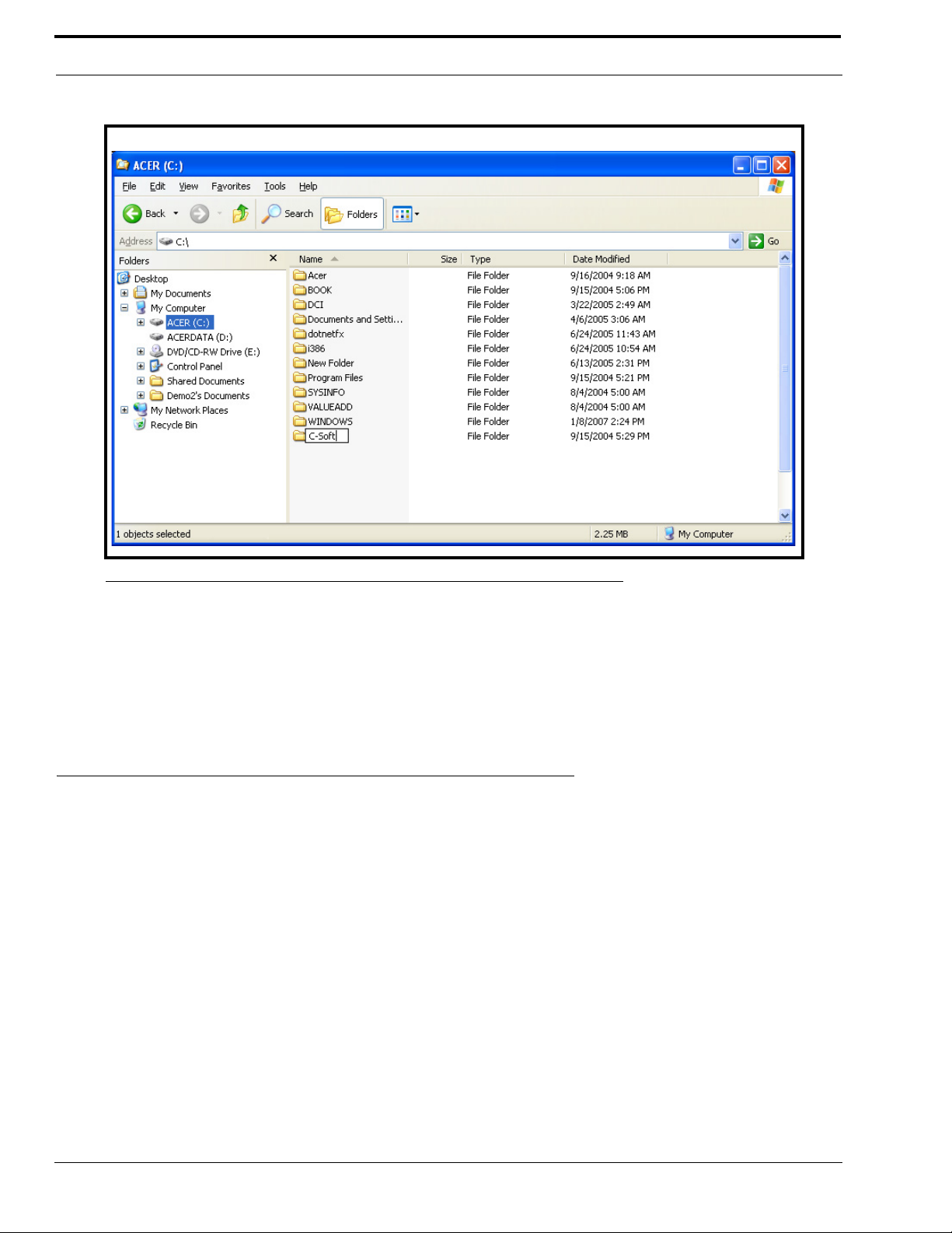
4. From the File menu, select New>Folder.
5. Rename the new folder to C-Soft.
9
Page 12
Installation and Setup
FIGURE 1. Creating a C-Soft directory
6. Copy the CSoftRuntime.exe, CSoftDesigner.exe, C-Soft Administrators Guide (LIT000082000.pdf), and
C6200F_Default.veg files from the C-Soft directory on the CD.
7. Create desktop shortcuts for the CSoftRuntime.exe and CSoftDesigner.exe files.
NOTE: Adobe
Reader® is required to view the C-Soft user manual. If Adobe Reader is not installed on the computer, a
copy of Adobe Reader is included on the installation CD.
License Dongle Driver Installation
Before running the CSoftRuntime program, a driver must be installed that allows the program to access the license dongle.
To install the license dongle driver, do the following:
NOTE: Ensure no USB devices are installed in the USB ports on the computer during the driver installation.
1. Close all programs.
2. Insert the C-Soft CD into the CD/DVD drive on the computer.
3. From the Start menu, select Run.
The Run window opens.
4. In the Open field, type D:\SPNComboInst1.0.5.exe (substitute the appropriate letter of your CD-ROM drive for D).
5. Follow the installation wizard instructions.
6. After successful completion of the installation, restart the computer.
10
Page 13
Initial Volume Control Settings
Initial Volume Control Settings
There are two sets of volume control settings on the computer that are crucial to the operation of the C-Soft programs. The first
set controls playback volumes and the second set controls the recording volumes. Before operation of the C-Soft programs,
these settings need to be checked and adjusted, if necessary.
Playback Volumes
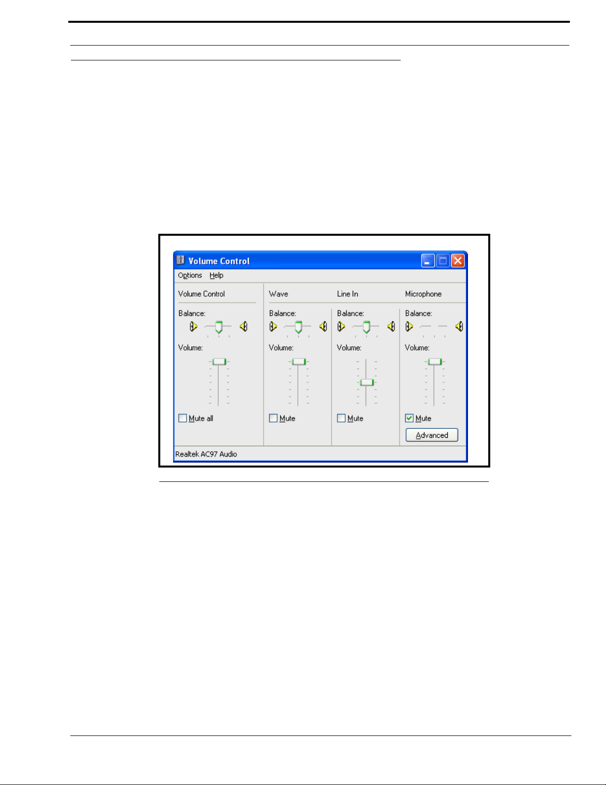
The settings for playback volume should be similar to those shown in Figure 2.
To set the playback volume, do the following:
1. Double-click the speaker icon in the system tray.
The Volume Control screen appears.
FIGURE 2. Volume Control window
2. Set the Volume Control and Wave Vol um e to the maximum level.
3. Select the Mute checkbox for the microphone volume.
If the mute check box is not selected, the microphone audio will feedback from the speakers.
4. Close the Volume Control screen.
Recording Volumes
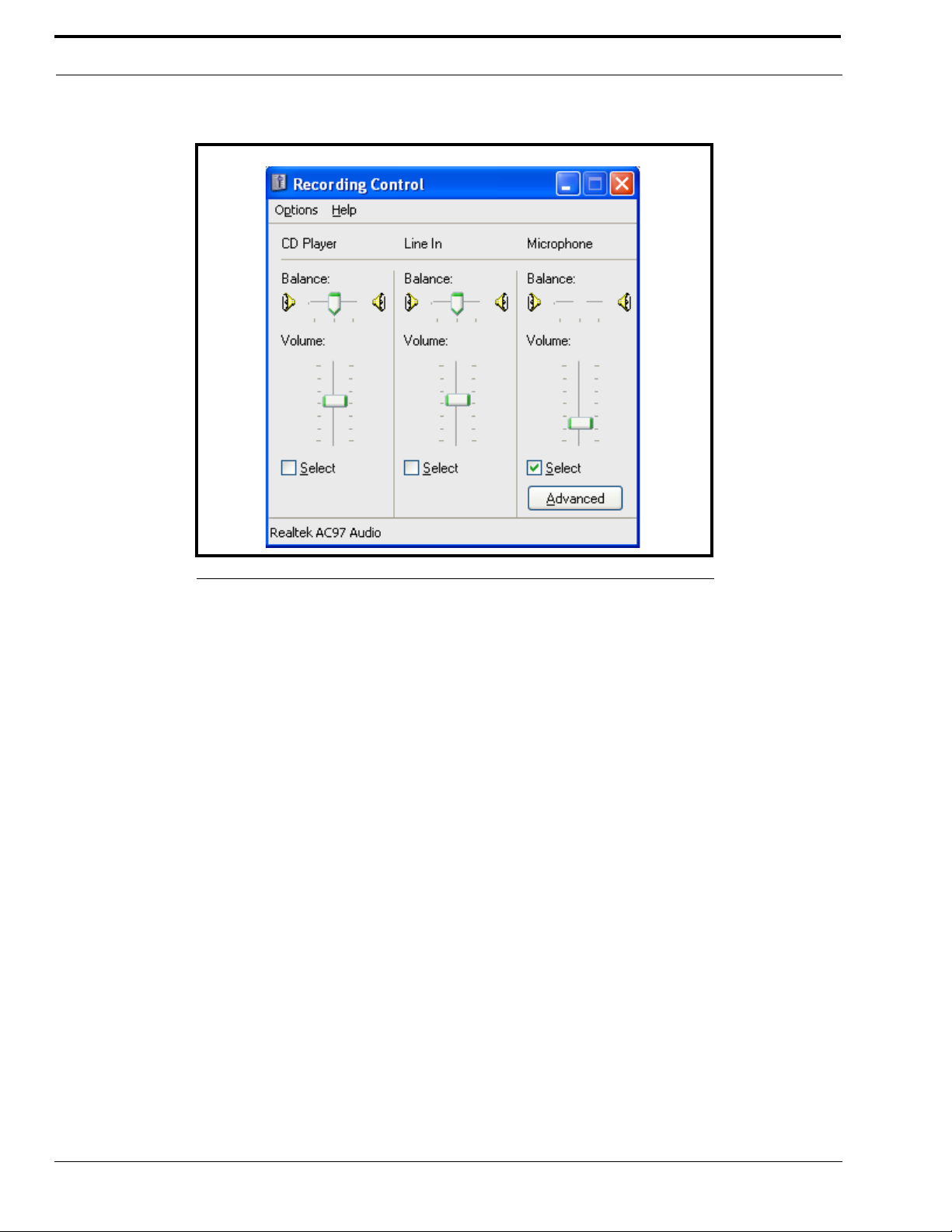
The settings for the recording volume should be similar to those shown in Figure 3 on page 12.
To set the recording volumes, do the following:
1. Double-click the speaker icon in the Windows tray.
The Volume Control window appears.
2. From the Options menu, select Properties.
The Properties window appears.
3. From the Adjust volume for area, select the Recording check box.
4. Select Microphone as the selected input.
11
Page 14
Installation and Setup
5. Click OK.
The Recording Control window appears.
FIGURE 3. Recording Control window
6. Set the microphone volume control to approximately the second tick.
7. Close the Recording Control window.
NOTE: When using an HB-3+ with your system, you must turn OFF the Mic Boost function. On the Recording Control
window, click Advanced. The Advanced Controls for Microphone window appears. Verify the Mic Boost check
box is disabled.
12
Page 15

CHAPTER 3
Communications System Design
Designing a C-Soft software console requires an understanding of the radio network and how the various radios and other
communication equipment are connected.
The first step in designing a C-Soft dispatch screen is to create a roadmap of the radio, console, and any other communication
equipment locations. This roadmap must include the following:
• Multicast addresses for each channel of TX (transmit) and RX (receive) communication.
• Port numbers for each channel of TX and RX communication.
• Base IP addresses assigned to each console or radio on the network and the number of frequencies that each radio
operates on.
• The number of channels each radio may operate on.
Network Requirements
Bandwidth
Each VoIP channel requires 50kBit of bandwidth while active. Full-duplex (audio in each direction) conversation requires
100kBit of bandwidth.
Some radio systems transmit “go-ahead” beeps when it is clear to talk. In order for the console operator to hear the beeps, the
system must support full-duplex communication. Full-duplex bandwidth may only be required for the first few seconds of a
conversation, due to the brief nature of the “go-ahead” beeps at the beginning of the transmission.
When using a PIB-223, C-6200, or the NI-223 for a telephone connection, a full 100kBit is required since it is a full-time, fullduplex conversation.
Multicast
In general, Telex systems require multicast to function. The network must be able to create a static multicast address that is
accessible at all times.
It is very common for networks to enable multicast after an IGMP (Internet Group Management Protocol) join message is sent
out, and then “prune” off branches after a period of time. Due to the intermittent usage patterns of two-way radio, such a
system can appear to work flawlessly for a period of time, then no longer work.
13
Page 16

Communications System Design
NOTE: When using Cisco technology, IP PIM dense mode is generally recommended. Generally speaking, sparse-
dense-mode can also be implemented effectively. We recommend explicitly joining the multicast group with an
IP IGMP static-join X.X.X.X command. For more information on Cisco and IGMP visit www.cisco.com
Internet Group Management Protocol (IGMP)
IGMP can be used to control where multicast is allowed to propagate. This should be limited to subnets that utilize the C-Soft
program as the dispatch console and only when used on an intermittent basis (when the C-Soft program is used for a period of
time and then shut down). When a console on the subnet is expected to be continually operational, multicast must be active for
that subnet at all times.
Network Performance
Networks should perform well under any loading conditions. The default audio delay is 120ms, plus any delay added by the
network. While delay alone does not cause issues, variable delay (jitter) does. Jitter in a network cannot exceed the
maximum packet buffer of any individual product buffer. Refer to the individual product manuals for these specifications. For
example, the IP-223 can handle approximately 600ms of network jitter.
NOTE: Losing more than 5% of the total packets transmitted compromises audio quality and system performance.
Optimally, packet loss should be less than 1%.
14
Page 17

CHAPTER 4
CSoftDesigner Program
The CSoftDesigner program is a console designer application used by system specialists to design and configure custom
dispatch screens. Various combinations of buttons, sliders, text, and popup windows can be included in a screen design. These
elements are then configured to operate on specific lines.
The designer can place elements in any location desired, and can include or omit functions based on the requirements of the
system and the console operator.
As discussed in the previous chapter, the first step in creating a user interface is defining how it will interact with an IP
network. This includes knowing the TX and RX port of each radio, the multicast group(s) used, the number of radios to
control, and the frequencies used by each radio.
Starting the CSoftDesigner Program
To start the CSoftDesigner program, double-click the CSoftDesigner desktop shortcut created during the installation of the
program.
CSoftDesigner Window
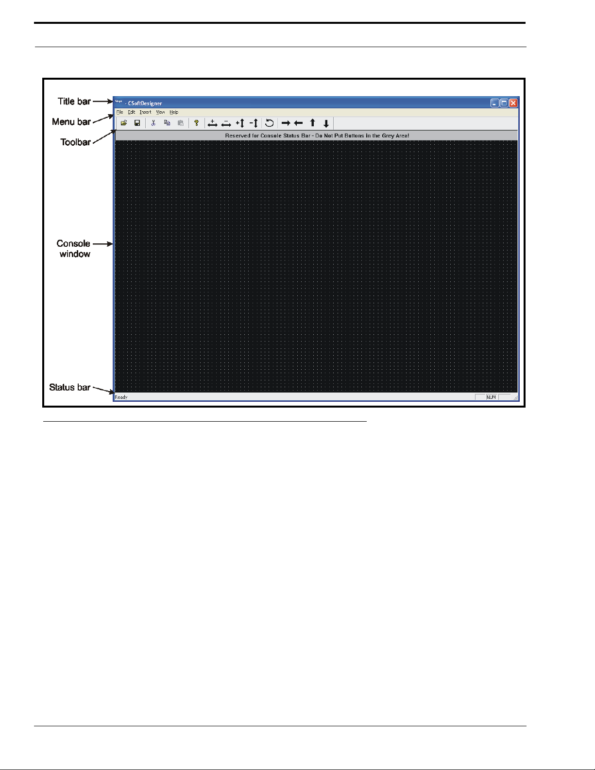
When the CSoftDesigner program is started, the console window shown in Figure 4 on page 16 is displayed. This window is
the workspace. It contains the commands and tools needed to design and configure a customized software console.
The CSoftDesigner workspace includes the following components:
• Title Bar
• Menu Bar
• Toolbar
• Console Window
• Status Bar
15
Page 18
CSoftDesigner Program
FIGURE 4. CSoftDesigner Workspace
Title Bar
The Title Bar is located across the top of each window. When a file is opened, the path sequence and file name are displayed
on the title bar.
Menu Bar
The Menu Bar is located directly below the title bar and displays menus that contain commands for accessing the
CSoftDesigner functions. For example, the Insert menu contains commands to add buttons, sliders, text, and popup windows.
Toolbar
The Toolb ar is located directly below the menu bar and provides quick, easy access to commonly used tasks. See Table 1 on
page 17 for a brief description of each button on the toolbar and the action taken when the button is selected.
To move the toolbar, do the following:
> Click, hold and drag the move handle on the toolbar or the title bar (blue bar) on a floating toolbar to the new
location.
The toolbar can be docked on any side of the window. It can also operate as a floating toolbar, inside or outside the
workspace.
16
Page 19
CSoftDesigner Window
To display the toolbar, do the following:
> From the View menu, select Toolbar.
The toolbar appears in the spot where it was previously closed.
To hide the toolbar, do the following:
1. From the View menu, select Toolbar.
The toolbar closes.
2. When the toolbar is floating, click the x button in the upper right corner of the toolbar window
The toolbar closes.
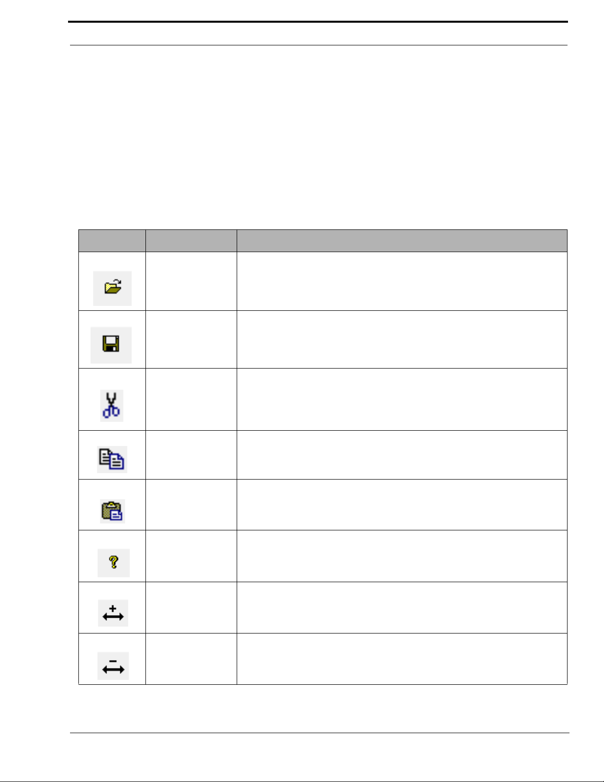
TABLE 1. CSoftDesigner toolbar
Icon Tool N ame Description
Open Open an existing console design. You can also use File|Open.
Save Save the current console design. You can also use File|Save.
Delete the selected item(s). You can also use Edit|Cut or the Delete key on the
Cut
keyboard.
NOTE: This does not place the cut item in the clipboard.
Copy the selected item(s). You can also use Edit|Copy.
Copy
NOTE: This places the copied item in the clipboard.
Paste
About
Insert the item(s) on the clipboard into the console design. You can also use
Edit|Paste.
Display the software version, company contact information, and various statistics
about the console design. You can also use Help|About CSoftDesigner.
Increase the width of the selected element. Proportionally increase the size of the
selected text.
Decrease the width of the selected element. Proportionally decrease the size of
the selected text.
17
Page 20

CSoftDesigner Program
TABLE 1. CSoftDesigner toolbar
Icon Tool Name Description
Increase the height of the selected element. Proportionally increase the size of the
selected text.
Decrease the height of the selected element. Proportionally decrease the size of
the selected text.
Rotate the selected popup window 90° counter-clockwise around the selected
popup button. Rotate the selected text 90° counter-clockwise.
Move the selected item(s) to the right.
Move the selected item(s) to the left.
Move the selected item(s) up.
Move the selected item(s) down.
Console Window
The Console Window displays the open console design. The console window contains a grid for easy alignment of elements
on the screen. The grid is a screen alignment tool and is not displayed on the dispatch screen.
Status Bar
The Status Bar is located at the bottom of the workspace window. Positioning the mouse over a tool or menu command
displays information about the tool or menu command on the status bar.
To display or hide the status bar, do the following:
> From the View menu, select Status Bar.
18
Page 21

Interface Element Manipulation
Interface Element Manipulation
The CSoftDesigner program is heavily dependent on the mouse for interacting with the elements that comprise the console
screen design. The mouse is used for selecting and moving objects, to access a form or window, and to perform actions on the
displayed element or text.
Several standard Windows shortcut keys are supported, and are listed next to the command on the menu. This section
describes the unique features of the CSoftDesigner program that are available to assist in the manipulation of the components
on the console window.
To select a single item, do the following:
> Click the desired item.
A red target is displayed on the selected element, or in the case of text, there is a bounding outline around the selected
text.
To select a group items, do the following:
1. Position the mouse pointer at the top and to the side of the objects to be selected.
2. Press and hold the left mouse button while dragging the mouse over the objects to be selected.
This draws a box around the items selected.
3. When all items are included within the box, release the mouse button.
A red target appears on the selected element(s), and, in the case of text, there is a box around the selected text, as
shown in Figure 5.
FIGURE 5. Selected items
Once an item(s) is selected, the screen design edit commands (see “Screen Design Edit Commands” on page 61) can be
performed on the item(s).
NOTE: A group of items cannot be moved using the mouse. Once selected, the positioning tools on the toolbar must be
used to move the items as a group. The arrow keys on the keyboard cannot be used to move the items.
To move an individual item, do the following:
> Select the item to be moved and then drag it to its new location on the screen.
19
Page 22

CSoftDesigner Program
To copy and move an individual item at the same time, do the following:
> Select the item while holding down the CTRL key and drag the item with the mouse to the new location on the
screen.
This moves the copied item into the new location with all the parameters of the copied item intact. When a popup
button is copied using the CTRL key, the popup window is also copied.
Using the CTRL key to copy items allows for large sections of the console screen to be designed, copied, and then modified
slightly to quickly design the console screen.
To change the line number associated with a group of items, do the following:
1. Select a group of items.
2. Right-click an element within the selected group.
A shortcut menu appears.
3. From the shortcut menu, select Group Line Number.
The UI Group Properties window appears.
4. From the Line to Associate Function With drop-down menu, select the line to associate with the selected group.
5. Click OK.
To change the font used on the elements in the group, do the following:
1. Select a group of items.
2. Right-click an element within the selected group.
A shortcut menu appears.
3. From the shortcut menu, select Group Font Change.
The Font window appears.
4. Select the Font, Font style, and Size you want to display on the elements.
A sample of the chosen style displays in the Sample field at the bottom of the Font window.
5. Click OK.
FIGURE 6. UI Group Properties and Font windows
The position of the popup window in relation to the popup button can be changed. Follow the procedure below to change the
position of the popup window.
To change the position of a popup window, do the following:
1. Right-click a UI element popup button.
A shortcut menu appears.
2. From the shortcut menu, select Open Popup.
A popup window appears.
20
Page 23
Interface Element Manipulation
3. Select the rotate icon from the toolbar.
Each click on the tool rotates the window 90° counter-clockwise around the selected popup button.
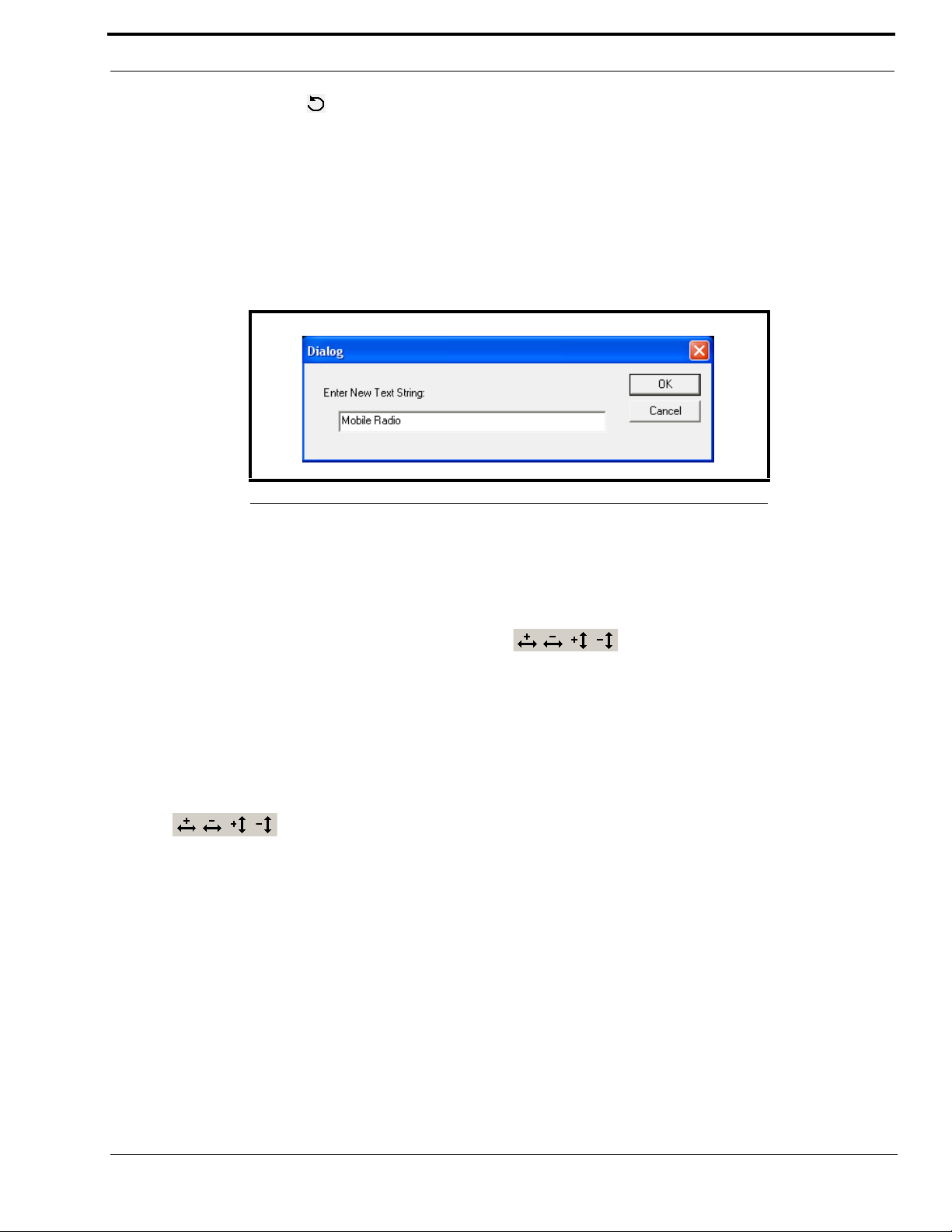
To change to a text string, do the following:
1. Select the text you want to change.
A bounding outline appears around the text.
2. Right-click on the text.
A Dialog window appears.
3. In the Enter New Text String field, make the changes to the text.
FIGURE 7. Enter New Text String window
4. Click OK to accept the changes. Otherwise, click Cancel.
The text is changed.
To change the size of a button, volume control or text string, do the following:
1. Select an item or group of items.
2. Use the increase or decrease width and height icons to resize the selected element(s).
To change the size of a popup window, do the following:
1. Right-click a UI element popup button.
A shortcut menu appears.
2. From the shortcut menu, select Open Popup.
A popup window appears.
3. With the popup button selected (see Figure 8), use the increase or decrease width and height icons
to resize the popup window.
21
Page 24
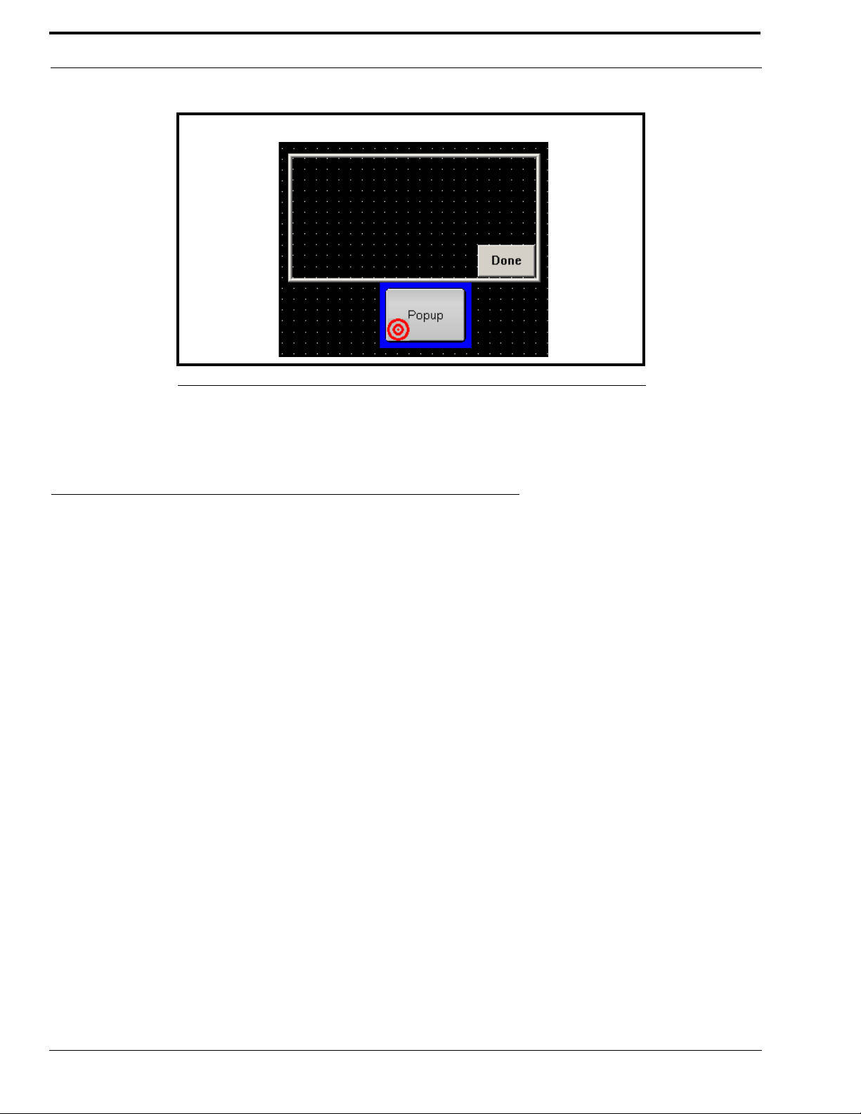
CSoftDesigner Program
FIGURE 8. Popup Button selected while popup window open.
Additional details on editing items on the console window are provided in Screen Design Edit commands in Table 1 on
page 17.
File Menu
The File menu contains commands for working with files. Each of the menu items is described below.
Open
Selecting Open from the File menu displays the Open window. Only files in the Designer file format (*.veg) can be opened by
the CSoftDesigner program.
Save
Selecting Save from the File menu displays the Save As window. The CSoftDesigner program saves all files in the Designer
File format (*.veg).
When a file is saved, the default name of C6200F_Default is in the File Name field in the Save As window. To use a different
file name, type the desired name for the file in the File Name field. When using a file name other than C6200_Default, the file
must be associated with the C-Soft program before it can be opened by the CSoftRuntime program. This is explained in detail
in “CSoftRuntime Program” on page 119.
22
Page 25
File Menu
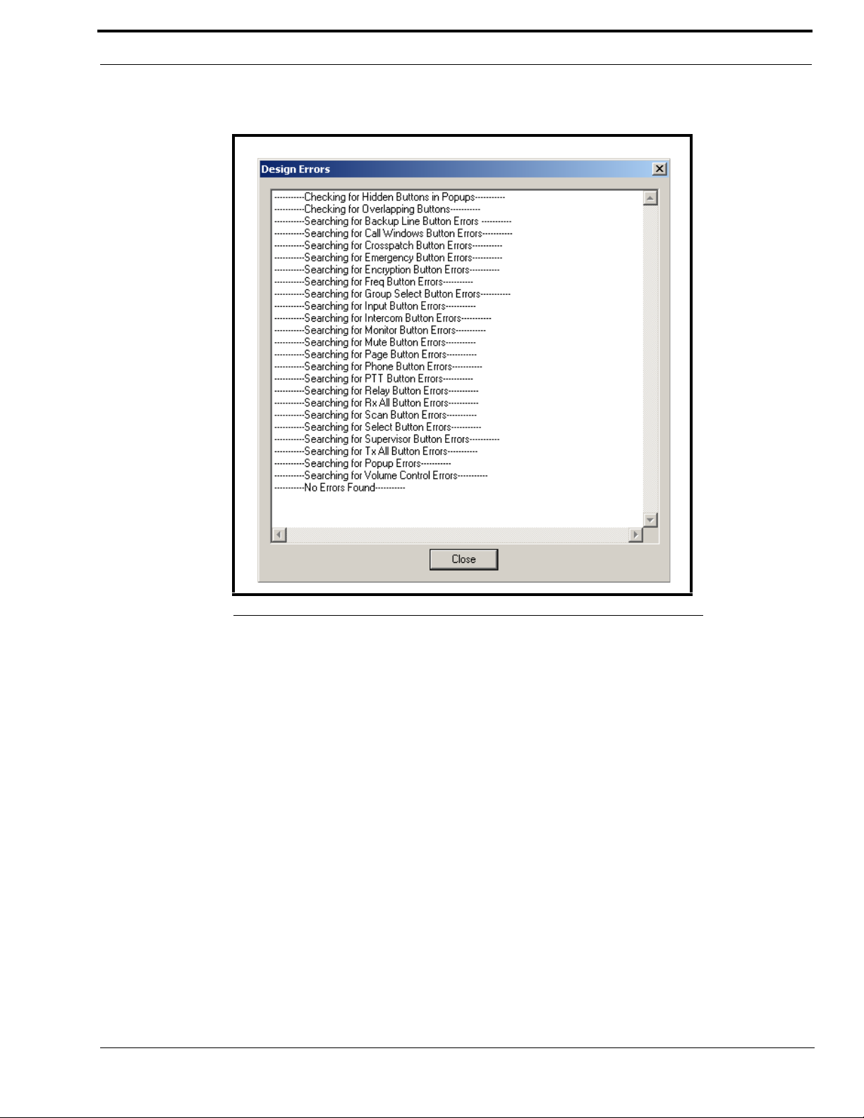
When the file is saved, the CSoftDesigner program performs a validation on the console design. The results of the validation
are displayed in the Design Errors window shown in Figure 9.
FIGURE 9. Design Errors window
If design errors are found, the last line of the list reads:
--------------------End of Error List--------------------
If no design errors are found, the last line of the list reads:
--------------------No Errors Found--------------------
NOTE: When all the results cannot be displayed within the window, scroll bars are provided on the window to scroll all
of the test results.
Exit
Selecting Exit from the File menu closes the CSoftDesigner program.
23
Page 26

CSoftDesigner Program
Edit Menu
The Edit menu contains commands for the setup and revision of the parameters for the VoIP network. This menu also contains
commands for making changes to the parameters that apply to the individual elements of the console screen design. This
section includes details about each of the commands that are on the Edit menu.
Setup Per Line Parameters
Selecting Setup Per Line Parameters from the Edit menu displays the Per Line Parameters window shown in Figure 10. The
Per Line Parameters window is used to configure the line types, addresses, port information, and line frequencies for the VoIP
network. This window allows up to 200 separate entries to be configured.
Many of the windows associated with the setup of the user interface elements depend on the entries on this setup window. The
parameters for all lines that are to be included in the console design must be set up on this window, along with the frequencies
associated with that line. If the line is not set up on this window, the line is not available as an option when setting up the user
interface elements.
The fields on this window are described on the following pages.
NOTE: Additions and changes can be made to the Per Line Parameters window at any time. However, if any user
interface elements have been placed on the console screen, the changes made to a line must also be changed on
the individual elements, if needed.
FIGURE 10. Per Line Parameters window
24
Page 27

Edit Menu
Line Number Field
The Line Number field displays the number of the line. This number is used for identification purposes in the design of the
console screen.
Line Type Drop-down Menu
The Line Type drop-down menu identifies the type of line being configured. Once a selection is made in the line type field, the
fields necessary to enter the setup information for that line type are enabled. The selections available are:
Disabled-Line is not enabled. Line 1 cannot be disabled.
Ve ga -Compatible with Telex radio control over IP products, such as the C-6200 or the IP-223
Not Used-
Phone- Allows the console to access a telephone line from across the network.
Line Name Field
The Line Name field is used to enter a descriptive name for the line. This name is used for identification purposes in the
design of the console screen. Up to 30 characters can be entered into this field.
RX and TX Multicast Address Fields
The RX and TX Multicast Address fields identify the broadcast address for all audio traffic. This dotted quad number must
be between 224.0.0.2 and 239.255.255.255. Devices can have the same or different Multicast Address for TX and RX
channels. Telex VoIP enabled equipment can use one multicast address for all lines with the port number defining the TX and
RX channels.
RX and TX Port Fields
The RX and TX Port fields identify the RX and TX port numbers. These numbers must be unique per channel and must be
greater than 1054.
In Figure 10, the RX Port is 1054 and the TX Port is 1254 for Line 1. All consoles that want to monitor receive audio for
channel 1 must share the same multicast address, as well as the same RX port number. Any console on the network that wishes
to transmit must set its port number to 1254 to cause the radio to keyup.
Base Radio IP Field
The Base Radio IP field identifies the IP address of the IP-223 used by the C-Soft program to create a socket between two IP
addresses. This address is required for the C-Soft program to create an internal ping command. It is also required for fullduplex mode (i.e., telephone mode) and to generate encoded message strings (i.e., 5/6 Tone, MDC 1200 and Fleetsync). We
recommend you include a base radio IP address for all lines within your system design.
The base radio IP address is periodically pinged to determine if a network connection still exists for a particular radio. If there
is no response received from the ping, the backup IP radio addresses are used.
A backup button is available for the console design. This button is used to force a switch, or to monitor whether the primary or
backup channel is used. Additional details on this feature are provided in “Backup Line” on page 71.
25
Page 28

CSoftDesigner Program
TTL (Time To Live) Field
The TTL field identifies the number of routers the multicast audio packets will go through before being stopped. The network
design dictates this value. If audio is not reaching a particular node on the network, increasing this value may correct the
problem.
Packet Delay Field
The Packet Delay field identifies the length of delay before playback, in 20ms packets. Some buffering of these packets must
occur before playback to help absorb network delays, jitters, and lost packets. The typical entry for this field is 6, which
translates to a delay of 120ms before playback (each packet is 20ms of audio). Larger values may be required for complicated
networks, smaller values for simpler networks.
The variable range for this field is 4 to 27.
TxMon Enable Check Box
The TxMon Enable check box indicates whether or not TX traffic being sent from other console operators can be monitored.
If selected, the console operator can monitor TX traffic from other console operators.
Scannable Check Box
The Scannable check box indicates whether or not the console operator is allowed to control the scan list of a particular radio.
If selected, the console operator is allowed to control the scan list of a particular radio. The frequency buttons for the line can
be used to add or delete radio channels from the scan list. Additional details on this feature are provided in “Frequency
Change” on page 81.
Echo Packets Enable Check Box
The Echo Packets Enable check box indicates if the system will operate on networks that do not support multicast. If
selected, the system is allowed to operate on networks that do not support multicast. The C-Soft program must be running at
all times to translate and transfer packets from one IP subnet to another.
A typical application has a number of radios spread throughout a network without multicast. In this case, the radio adapters
(IP-223s or C-6200s) are programmed to send packets to the IP address of the PC running the C-Soft program with Echo
Packets enabled.
26
Page 29
Edit Menu
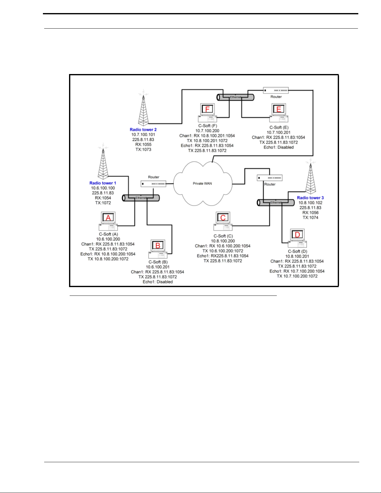
Figure 11 shows an example of an Echo Packet system where three different radios are connected through a WAN. In each of
the subnets, a single copy of the C-Soft program is used to communicate to the radio in its subnet. A second console is used to
echo the audio traffic to other copies of the C-Soft program. The C-Soft program also echoes all traffic to a multicast address
within its subnet so that additional consoles can be added to the system by specifying the multicast address.
FIGURE 11. Echo Packet System Diagram
Traffic received on the address of the RX packet (typically multicast but under this scenario it is the unicast address of the
radio remote) is copied and output to the RX echo packet address.
The echo packet RX address would typically be the multicast address. This enables the C-Soft program to function as a
gateway for other consoles on the same local network segment. Local consoles transmit and receive the multicast address, and
the C-Soft program translates and sends the packets to the radio directly.
The TX side works in a similar fashion, except the packets received on either address are echoed to the other address and when
the C-Soft program transmits, it sends to both ports simultaneously.
NOTE: Echo packets support radio traffic only. Echo packets do not support Phone or NEO-10 functions.
Backup IP Setup Button
Selecting the Backup IP Setup button opens the Backup IP Address Setup window shown in Figure 12. If the primary radio
interface identified for the line fails, the network resources identified in this window provide a backup for the line.
27
Page 30
CSoftDesigner Program
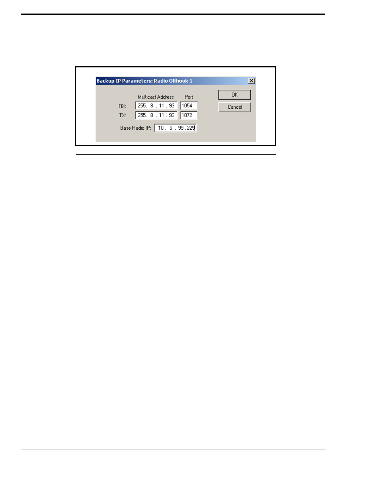
Backup IP Parameters Window
The Backup IP Parameters window identifies the network resources used if the primary radio interface identified for the line
fails (see Figure 12).
FIGURE 12. Backup IP Parameters window
RX Multicast Address and Port Fields
Use the RX Multicast Address and Port fields to configure the receive multicast address and port to use if the primary
receive path fails.
TX Multicast Address and Port Fields
Use the TX Multicast Address and Port fields to configure the transmit multicast address and port to use if the primary
transmit path fails.
Base Radio IP Field
Use the Base Radio IP field to configure the backup IP Address of the base radio, should the primary address fail.
OK Button
Selecting the OK button saves the entries and closes the window.
Cancel Button
Selecting the Cancel button clears any entries made and closes the window.
Freqs Button
Selecting the Freqs button opens the Per Line Frequency Setup window shown in Figure 13 for the selected line.
Per Line Frequency Setup Window
The Per Line Frequency Setup window is used to enter the parameters for the individual function tones available for the line.
28
Page 31

Edit Menu
NOTE: Additions and changes can be made to the Per Line Frequency Setup window at any time. However, if any user
interface elements have been placed on the console screen, the changes made to a line must also be changed on
the individual elements, if needed.
FIGURE 13. Per Line Frequency Setup window
Enable Check Box
The Enable check box indicates whether or not options for the corresponding frequency numbers are available in the
CSoftDesigner program. If selected, the options for the corresponding frequency number are available within the rest of
the CSoftDesigner program and to the option within this window.
Frequency Name Field
The Frequency Name field is used to enter a descriptive name (up to 12 characters) for the frequency. This name is used
to identify the frequency for the elements used in the design of the console screen and is made available for selection in a
list of variables. Once selected from the list of variables, the changes made to a frequency must be refreshed on the user
interface button.
Pair Mode Setup Check Boxes
The Pair Mode Setup check boxes allows function tones to have control functions that are not used for actual control of
the radio. There are four wildcard groups available per line. Function tones 1 and 2 are not allowed in a wildcard group
and a function tone may not be selected in more than one group. One function tone from each group can be active at a
time, plus either F1 or F2.
29
Page 32

CSoftDesigner Program
RX Block Lines Display Box
The RX Block Lines display box contains a list of all the lines. Selecting a line in the list mutes that line when the line to
which the details in this window apply is switched to transmit. This allows the console operator to transmit on a radio that
has overlapping coverage with other radios without getting feedback from the radios that are receiving the transmitted
signal. This function also operates when a parallel console is detected transmitting on the line.
Highlight the lines to mute during a transmission by clicking the line (s) in the display box. To clear a selection, click the
line(s) a second time.
Close Button
Selecting the Close button saves the entries and closes the window.
Signal Setup Button
Selecting the Signal Setup button opens the Signaling Setup Parameters window shown in Figure 14.
Signaling Setup Parameters
Use the Signaling Setup Parameters window to program a unique ANI (automatic numbering indicator) Encode format
information at the per-line level in the system.
FIGURE 14. Signaling Setup Parameters window
30
Page 33

Edit Menu
Per Line Console ID field
The Per Line Console ID number is the ID number (up to 8 characters) required to communicate with this console position.
NOTE: The console can be given a unique identifier per line. The identifier is used in message and call addressing
systems, such as 5/6 Tones.
Auto Ack Setup Group Box
Auto Ack Type drop down menu
The Auto Ack Type drop-down menu allows you to choose the signaling type desired to acknowledge receipt of a call.
Field values are:
• Disabled
• Single-Tone
• Signaling (i.e., 5/6 Tone tone formats) - When Signaling is selected, the Auto Ack Call Format field becomes
available (see “Auto Ack field” on page 33).
Auto Ack Delay field
The Auto Ack Delay field allows you to configure the lead in delay for received messages configured to transmit an
acknowledgement back to the calling radio. Field values can range from 0-9999ms.
Signaling Delays Group Box
Initial Delay field
The Initial Delay field represents the lead-in delay value for console-generated messages transmitted to the field radios.
Note, for iDen control, the initial delay should be set to 0ms.
Field values can range from 0-9999ms
End Delay field
The End Delay value represents the delay at the end of transmitted messages to the field. It delimits the tone string. It is
recommended to enter a value in this field. Do NOT leave blank.
Field values can range from 0-9999ms.
Global Group Box
Set All Lines check box
When the Set All Lines check box is enabled, the program settings are saved for all lines in the system design.
Single Tone Auto Ack Setup Group Box
Frequency field
The Frequency field represents the frequency generated during a single tone ACK.
Field values can range from 0-4000Hz.
31
Page 34

CSoftDesigner Program
Duration field
The Duration field represents the duration of the single tone ACK.
Field values can range from 25-9999ms.
Level field
The Level field represents the relative level, in dB, the single tone ACK sends.
Field values can range from -20dB to +12dB.
Signaling Setup Group Box
Signaling Type drop-down menu
Use the Signaling Type drop-down menu to configure the signaling type used when generating a call.
Field values are:
• CCIR1
• CCIR2
• DTMF
• DZVEI
• EEA
• EURO
• KENWOOD 5 TONE
Digit Duration field
The Digit Duration field represents the length of time the digit tone plays when it is active.
Field values can range from 25-9999ms.
Interdigit Duration field
The Interdigit Duration field represents the length of time between the digit tones within a group.
Field values can range from 25-9999ms.
Pause Duration field
The Pause Duration field represents the length of time allowed between transmitted groups.
Field values can range from 25-9999ms.
• MODAT
• NATEL
• PCCIR
• PDZVEI
• PZVEI
• ZVEI1
• ZVEI2
Preamble Duration field
The Preamble Duration field represents the length of time the first tone digit plays. With some radio systems the first
tone needs to be longer than subsequent tones. For example, the first tone may be used to activate a dormant (battery
saving) state.
Field values can range from 25-9999ms.
32
Page 35

Edit Menu
Level field
The Level field represents the relative level, in dB, the encoded message sends.
Field values can range from -20dB to +12dB.
Twist Level field
The Twist L eve l field represents the relative level difference, in dB, of high and low tones generated when using DTMF
tone types. This field is only active when DTMF is the selected tone type.
Field values can range from -10dB to +10dB.
Group Digit field
The Group Digit field represents the group identification defined by the radio system. Typically this digit is not used
anywhere else in the system.
Field values can be 0 - 9 or A - D, #.
Repeat Digit
The Repeat Digit field identifies a repeat digit. Repeat digits are used to signal that a digit has been repeated. The repeat
digit replaces the repeated digit. Repeat digits are used to maintain tone transitions at appropriate intervals, which
simplifies the decode function.
For example, the repeat digit is E and the subscriber ID is 23335. The encoder string would actually send a tone string of
23E35.
Call Setup Group Box
Auto Ack field
The Auto Ack field represents the message sent as an auto acknowledgement (i.e., 5/6 tone signaling) setup as the Auto
Ack type (see “Auto Ack Type drop down menu” on page 31). The message is sent after receiving a SelCall (Select Call).
This is automatically generated. Up to 32-characters can be entered into this field.
Field values can be:
For DTMF Format - Allows for 0-9, *, #, A-D, G, I, K, P, R, and S.
For 5-Tone Format - Allows for 0-9, A-F, G, I, K, P, R, and S (Use the a A-F digits as more available tones for the 5-
tone signal).
For a complete description of the values G, I, K, P, R and S, see Table 2.
Emerg Resolved field
The Emerg Resolved (emergency resolved) field represents the message sent each time an emergency resolve button, for
that line, is pressed. This is also used if an emergency is sent to a specific console ID and auto acknowledge is enabled.
A message is only sent out if the emergency is active.
Up to 32-characters can be entered into this field.
33
Page 36

CSoftDesigner Program
Field values can be:
For DTMF Format - Allows for 0-9, *, #, A-D, G, I, K, P, R, and S.
For 5-Tone Format - Allows for 0-9, A-F, G, I, K, P, R, and S (Use the a A-F digits as more available tones for the 5-
tone signal).
For a complete description of the values G, I, K, P, R and S, see Table 2.
PTT BOT field
The PTT BOT (push-to-talk beginning of transmit) field represents the message sent each time the PTT button is pressed
on the console at the beginning of transmit. Up to 32-characters can be entered into this field.
Field values can be:
For DTMF Format - Allows for 0-9, *, #, A-D, G, I, K, P, R, and S.
For 5-Tone Format - Allows for 0-9, A-F, G, I, K, P, R, and S (Use the a A-F digits as more available tones for the 5-
tone signal).
For a complete description of the values G, I, K, P, R and S, see Table 2.
PTT EOT field
The PTT EOT (push-to-talk end of transmit) field represents the message sent each time the PTT button is pressed on the
console at the end of transmit.Up to 32-characters can be entered into this field.
Field values can be:
For DTMF Format - Allows for 0-9, *, #, A-D, G, I, K, P, R, and S.
For 5-Tone Format - Allows for 0-9, A-F, G, I, K, P, R, and S (Use the a A-F digits as more available tones for the 5-
tone signal).
For a complete description of the values G, I, K, P, R and S, see Table 2.
Call 1 through Call 10 Format field
The Call 1 through Call 10 Format fields represent the message sent when selected by the console operator on the Per
Line Call History, Call List Window, or the Manual Call List window. See Figure 15. Up to 32-characters can be entered
into this field.
Field values can be:
For DTMF Format - Allows for 0-9, *, #, A-D, G, I, K, P, R, and S.
For 5-Tone Format - Allows for 0-9, A-F, G, I, K, P, R, and S (Use the a A-F digits as more available tones for the 5-
tone signal).
34
For a complete description of the values G, I, K, P, R and S, see Table 2.
Page 37

Edit Menu
Call 1 through Call 10 Label field
The Call 1 through Call 10 Label fields represent the label applied to the button on the Per Line Call History, the Manual
Call Window, and the Call List Window popup button. See Figure 15. Up to 31-characters can be entered into this field.
Field values can be: Any Keyboard entries.
FIGURE 15. Per Line Call History
TABLE 2. Call Setup Group Format Descriptions
VALUE DESCRIPTION
I
G
S
P
R
K
Stands for Console ID. Use the “Per Line Console ID field” on page 31 to configure the Console ID. This value must match
the number of digits in the Console ID.
For example, the Console ID is 123, the value entered in the format field would be III.
Stands for Group. This is used to make a Group Call. The Group ID is configured on the “Edit Group ID List” on page 57 to
configure Group IDs. This value must match the number of digits in the Group ID.
For example, the Group ID is 5000A, the value entered in the format field would be GGGGG.
Stands for Status. Use the “Edit Status Message ID List” on page 58 to configure Status IDs
Stands for Pause. When you want to format a pause into the string being sent out, use a P. Pause Duration is set up in
Signaling Setup.
Stands for Radio ID. You must enter the exact number of digits in the radio ID. For example, if you pick User ID 12356, you
must enter RRRRR.
Takes all the digits in the User ID of the type of call being made. In this format, you can enter a K, which will enter all
numbers associated with the User ID column.
You can use any combination of these values with the numerical digits to create formats.
35
Page 38

CSoftDesigner Program
AutoFill Line Properties
Selecting the AutoFill button opens the AutoFill Line Properties window shown in Figure 16. This window is used to
eliminate repetitious data entry by automatically populating the corresponding fields on the Per Line Parameters window with
the entries shown in the AutoFill Line Properties window. The RX and TX Port entry automatically increments by one for
each line that is filled. Enter the starting line number and ending line numbers to automatically fill in the appropriate field.
FIGURE 16. AutoFill Line Properties
OK Button
Selecting the OK button saves the entries and closes the window.
Cancel Button
Selecting the Cancel button clears any entries made and closes the window.
36
Page 39

Edit Menu
Setup Global Parameters
Selecting Setup Global Parameters from the Edit menu displays the Global Properties Setup window shown in Figure 17.
The fields on this window are described on the following pages.
FIGURE 17. Global Properties Setup window
DTMF Setup Group Box
The DTMF Setup fields affect the operation of DTMF keypad keys if they are included in the console design.
Flywheel Field
The Flywheel field identifies the amount of time, in ms, allowed to pass between clicks of different DTMF keypad keys
before the radio is keyed down by the console.
37
Page 40

CSoftDesigner Program
Level Field
The Level field identifies, in dB, the relative level to be transmitted. The actual level transmitted by the radio varies
depending on the system. This field allows the console designer to adjust the relative level up or down after the remainder
of the system is aligned and operational.
Supervisor Group Box
Timeout Field
The Timeout field identifies the amount of time, in seconds, that supervised lines are released from supervision when
there is no TX or RX activity. A value of zero (0) disables the timer.
HB3 Serial Port Drop-down menu
The HB3 Serial Port drop-down menu identifies the PC serial port connection for the HB-3 Headset Adapter Panel. The HB3 unit allows the connection of standard dispatcher accessories including a desk mic, 2 headsets, and footswitches. This
functionality allows the C-Soft program to respond to PTTs from a footswitch without requiring the console operator to move
a mouse cursor to the C-Soft application. This functions even if the C-Soft application does not have the focus.
Local Console IP Address Fields
The Local Console IP Address fields identify up to 10 base IP addresses of the C-6200 and C-Soft consoles that reside in the
same room. These addresses are used for the Ethernet crossmute function.
The source of the audio is examined by the C-Soft program, and if the source is from a console in this list, the audio is muted.
An exception to this muting rule is if the HB-3 is connected and the headset is turned ON. In this case, the received audio is
routed to the headset earpiece and is played, ignoring the crossmute condition.
To allow each position to have its own crossmute settings without requiring a different design file, the Local Console IP
Address fields can be populated from a file. To create this file, enter up to 20 IP addresses (one per line) into a .txt file and then
save the file as csoft_crossmutes.txt. Place the file in the same directory as the CSoftRuntime.exe file. The IP addresses are
loaded from this file and replace the entries in the Global Properties Setup window.
IP Address or Name of License Server Field
The IP Address or Name of License Server field identifies the IP address or the name of the license server that the key
management driver is installed on. This allows a remote key server to be used for license management.
When a single PC is loaded with the key management driver, up to 10 individual keys can be connected to the server PC. Five
of each key type is supported by the key management driver software. This means that 5 USB and 5 parallel port keys can be
connected to the server.
Once the server PC is set up, each individual computer that has the license dongle driver installed on it (see “License Dongle
Driver Installation” on page 10), should have the direct IP address or the network name of the server PC entered in the IP
Address or Name of License Server field. The server then allows concurrent use of the C-Soft software up to its key count
number. This method has the advantage of making the C-Soft software more portable across a network.
If more than 10 concurrent licenses are required, contact Telex Sales Department for license server options (see page ii).
Rather than entering the IP address or the name of the license server that the key management driver is installed on, dual mode
can be entered in the field as the license server. When dual mode is entered in the field, the console looks for a license dongle
on the local machine first. If a license dongle is not found, the console looks for license servers on the network. This option
allows multiple license servers to reside on a network, providing greater redundancy and fault tolerance, however, this option
can also cause a slightly slower boot-up.
38
Page 41

Edit Menu
Window Controls Check Boxes
The Window Controls check boxes indicate whether or not the standard windows controls are included on the dispatch
console screen. The following selections are available:
Open on Activity - when selected, automatically opens a popup window if line activity is occurring within the popup
window.
Allow Minimize - when selected, allows the console operator to minimize the dispatch screen to a button on the
toolbar.
Allow Maximize - when selected, allows the console operator to maximize the dispatch screen.
Allow Resize - when selected, allows the console operator to resize the dispatch screen.
Allow Move - when selected, allows the console operator to move a dispatch screen that has been resized.
Allow Close - when selected, allows the console operator to close a dispatch screen. Note, if this selection is not
enabled, the only way to shut down the dispatch screen is to use the Windows Task Manager.
IP Interface Spin Box
The IP Interface spin box is used to select the software console Ethernet interface. The C-Soft program can be configured to
utilize any of the first four interfaces.
If no traffic is detected on the selected interface, select a different interface, save the file, and restart the console.
Ring Sound Drop-down Menu
The Ring Sound drop-down menu is used to select the ring sound.
Background Color
The Background Color displays the background color for the console and popup windows. Use the drop-down menu to open
a palette to select the desired color.
The default color is black.
Logo Fields
The Logo fields provide the ability to include a bitmap logo on the dispatch screen. When a logo is added to the design of the
dispatch screen, it is not displayed on the screen in the CSoftDesigner program, but the logo is displayed on the CsoftRuntime
dispatch screen.
Bitmap Filename Field
The Bitmap Filename field identifies the file name of the custom bitmap logo to be displayed on the dispatch screen. The
file must be a bitmap and it must be located in the same directory as the CSoftRuntime.exe file.
The file name entry cannot exceed 19 characters
Position Drop-down Menu
The Position drop-down menu is used to select the location of the custom bitmap logo on the dispatch screen.
39
Page 42

CSoftDesigner Program
Audio Routing and Muting Check Boxes
Use the Audio Routing and Muting check boxes to allow control of audio routing. These items should be set based on
console operator preferences.
FIGURE 18. Audio Routing and Muting fields - Global Properties Setup window
Kill Lines on Crosspatch Check Box
The Kill Lines on Crosspatch check box indicates whether or not the console operator has the ability to transmit on a line that
has been included in a crosspatch by another console operator. If selected, the console operator cannot transmit on a line that
has been included in a crosspatch by a parallel console operator. Otherwise, the console operator is allowed to transmit on the
lines even if another console operator has included the lines in a crosspatch.
Enable Sticky ANI Check Box
The Enable Sticky ANI field indicates whether or not the ANI displayed on the select button remains visible until the next
call is received. If selected, the ANI is displayed on the element button until the next call is received.
Enable Residue ANI Check Box
The Enable Residue ANI check box indicates the last valid unit’s ANI that called. If another call is received from another unit
that does not have an ANI, this element button field is not updated.
Allow Freq Update Anytime Check Box
The Allow Freq Update Anytime check box indicates whether or not frequency update information is accepted at any point
in the RX stream.
Selecting this field ensures the frequency update information is only accepted at any point in the RX stream. Otherwise, the
frequency update information is only accepted at the beginning of a call, before audio playback begins.
Disable Local iDEN Tones Check Box
The Disable Local iDEN Tones check box indicates the console will not generate go ahead beeps. Beeps are generated by the
iDEN radio attached to the system. If selected, the iDEN tones are not generated by the console.
Radio Ping Interval Field
The Radio Ping Interval field identifies the time, in seconds, between Ping attempts on the base radio IP address. The typical
amount of time is 300 seconds or five minutes. A value of zero (0) disables the function.
40
Page 43

Edit Menu
RX Block Delay Field
The RX Block Delay field identifies the amount of time, in ms, the release of the RX blocked line is delayed. The RX blocked
lines are selected on the Per Line Frequency Setup window, see “Echo packets support radio traffic only. Echo packets do not
support Phone or NEO-10 functions.” on page 27. This delay allows any IP and system delayed audio to end before releasing
the mutes.
Tones/DTMF Sidetone Level Field
The Tones/DTMF Sidetone Level field identifies the level, in dB, of the sidetone output for tone generation. This includes
DTMF and single tones such as paging and alert tones. This setting controls the level of the output tones to the speaker.
MIC AGC Enabled Check Box
The MIC AGC (Automatic Gain Control) Enabled check box indicates whether or not the C-Soft program supports a
software based microphone AGC. If selected, this function helps to even out speech level variations caused by the use of
different microphones, different speaking distances to the microphone, and different volumes of speech.
Target Level Field
The Target Level field identifies the audio level, in dB, the MIC AGC packets are adjusted to. If the measured audio level
is above the target level, the audio is reduced in gain. If the incoming level is below the target, up to 15dB of gain is
applied to bring the level up.
Min Active Field
The Min Active field identifies the audio level, in dB, when the AGC software is to stop trying to adjust the audio level.
If audio below this level is detected, no attempt is made by the AGC to adjust the audio. This prevents open mics from
amplifying background noise onto the transmit channel.
Phone Ring Multicast and Port Fields
The Phone Ring Multicast and Port fields identify the IP address and port number that the ring signal is broadcast to. The
entry in this field should correspond to the values set in a C-6200 console that has the actual phone card interface or an IP-223
with PIBs attached.
NEO-10 Update Multicast and Port Fields
The NEO-10 Update Multicast and Port fields identify the multicast address and port number of the NEO-10 Network I/O
device. The entry in this field should correspond to the entry on the NEO-10 Multicast Setup screen.
The NEO-10 Network I/O device sends out a UDP packet anytime one of its inputs or outputs changes states. The C-Soft
program monitors this traffic and allows all users of the equipment to see changes in the status of inputs or outputs.
Positional Recording Group Box
The Positional Recording fields allow the audio from a console position to be sent directly to a recorder. Each speaker and
microphone can be independently sent to the Telex Network Recording device.
Select the desired audio source to enable it. Enable only the audio sources that need to be recorded.
NOTE: The microphone is only recorded during activity, such as PTT or a telephone call.
41
Page 44

CSoftDesigner Program
Enter the static IP address of the Telex Network Recorder into the appropriate field. This sets the network recorder to look for
packets from this position. Enter a unique port number into the appropriate field. If multiple consoles are in use, this option
requires a separate configuration to be created for each console.
OK Button
Selecting the OK button saves the entries and closes the window.
Cancel Button
Selecting the Cancel button clears any entries made and closes the window.
Setup Global Call Parameters
Selecting Setup Global Call Parameters from the Edit menu displays the Global Call Parameters Setup window shown in
Figure 19. This window is used to configure the Global Call parameters for the console. The fields on this window are
described on the following pages.
FIGURE 19. Global Call Parameters window
Window Titles Group Box
Active Emergency Field
The Active Emergency field allows you to name the window that appears when the Active Emergency button is clicked
in the CSoftRuntime program.
This field can contain up to 31 characters.
42
Page 45

Edit Menu
Emergency History Field
The Emergency History field allows you to name the window that appears when the Emergency History button is clicked
in the CSoftRuntime program.
This field can contain up to 31 characters.
Per Line Call History Field
The Per Line Call History field allows you to name the window that appears when the Per Line Call History button is
clicked in the CSoftRuntime program.
This field can contain up to 31 characters.
Call List Field
The Call List field allows you to name the window that appears when the Call List button is clicked in the CSoftRuntime
program.
This field can contain up to 31 characters.
Manual Call List Field
The Manual Call List field allows you to name the window that appears when the Manual Call List button is clicked in
the CSoftRuntime program.
This field can contain up to 31 characters.
Status List Field
The Status List field allows you to name the window that appears when the Status List button is clicked in the
CSoftRuntime program.
This field can contain up to 31 characters.
Call Options Group Box
Call-to-Console Color Field
The Call-to-Console Color field allows you to choose the displayed background color for an incoming call matching the
console’s ID number. All other calls, if monitored, have a white background.
Change Color Button
Use the Change Color button to open the color palette. From the color palette you can choose the color you want to
display when a specified call is received at the console.
Date Format Drop Down Menu
Use the Date Format drop down menu to select the date format displayed in the call logs.
The format choices are: MM/DD/YYYY and DD/MM/YYYY.
43
Page 46

CSoftDesigner Program
Display All Calls Check Box
The Display All Calls check box allows you to choose from displaying only calls directed to the console ID to displaying
all calls. If selected, all calls are displayed. Otherwise, when the check box is not selected, only calls with the console ID
display.
Per Line Call History Window Lines Field
Use the Per Line Call History Window Lines field to set the number of lines displayed in the Call History window.
Once the call history window is full, the oldest call is removed. The field values range from 1 - 500.
Per Line Call History Font Size Field
Use the Per Line Call History Font Size field to specify the text size for the call history log. The field values range from
1 and 72.
Emergency Call History Window Lines Field
Use the Emergency Call History Window Lines field to set the number of lines displayed in the Emergency Call History
window. Once the call history window is full, the oldest call is removed. The field values range from 1 - 500.
Emergency Call History Font Size Field
Use the Emergency Call History Font Size field to specify the text size for the emergency call history window. The field
values range from 1 to 72.
Active Emergency Font Size Field
Use the Active Emergency Font Size field to specify the text size for the active emergency call history window. The field
values range from 1 to 72.
Call List Font Size Field
Use the Call List Font Size field to specify the text size for the Call List window. The field values range from 1 to 72.
Status List Font Size Field
Use the Status List Font Size field to specify the text size for the Status List window. The field values range from 1 to 72.
Labels on Buttons Group Box
ACK Field
Use the ACK field to create the button label seen in the Active Emergency window. This field can contain up to 31
characters.
Resolved Field
Use the Resolved field to create the button label seen in the Active Emergency window. This field can contain up to 31
characters.
Done Field
Use the Done field to create the button label seen in all call windows. This field can contain up to 31 characters.
44
Page 47

Edit Menu
Set Status Field
Use the Set Status field to create the button label seen in the Per Line Call History, Manual Call List and Call List
windows. This field can contain up to 31 characters.
Clear Field
Use the Clear field to create the button label seen in the Set Status window. This field can contain up to 31 characters.
Cancel Field
Use the Cancel field to create the button label seen in the Set Status window. This field can contain up to 31 characters.
Backspace Field
Use the Backspace field to create the button label seen in the Manual Call window. This field can contain up to 31
characters.
Digit A-F Fields
Use the A-F fields to create the button labels seen in the Manual Call window. This field can contain up to 10 characters,
alphabetical and numerical.
Labels on Column Headings and Static Text Group Box
Date Field
Use the Date field to create the column label applied to the Date column in call windows. This field can contain up to 31
characters.
Time Field
Use the Time field to create the column label applied to the Time column in call windows. This field can contain up to 31
characters.
Channel Field
Use the Channel field to create the column label applied to the Channel column in call windows. This field can contain up
to 31 characters.
Freq Field
Use the Freq field to create the column label applied to the Frequency column in call windows. This field can contain up
to 31 characters.
Status Field
Use the Status field to create the column label applied to the Status column in call windows. This field can contain up to
31 characters.
User ID Field
Use the User ID field to create the column label applied to the User ID column in call windows. This field can contain up
to 31 characters.
45
Page 48

CSoftDesigner Program
Calling ID Field
Use the Calling ID field to create the column label applied to the Calling ID column in call windows. This field can
contain up to 31 characters.
Status ID Field
Use the Status ID field to create the column label applied to the Status ID column in call windows. This field can contain
up to 31 characters.
Alias Field
Use the Alias field to create the column label applied to the Alias column in call windows. This field can contain up to 31
characters.
ID Type Field
Use the ID Type field to create the column label applied to the ID Type column in call windows. This field can contain up
to 31 characters.
OK Button
Selecting the OK button saves the entries and closes the window.
Cancel Button
Selecting the Cancel button clears any entries that were made and closes the window.
Defaults Button
Selecting the Default button resets all parameters to their default values.
46
Page 49

Edit Menu
Pager Setup
Selecting Setup Pagers from the Edit menu displays the Pager Setup window shown in Figure 20. The fields on this window
are described below.
FIGURE 20. Pager Setup window
Pager Number Field
The Pager Number field displays the number of the pager. Up to 10 simultaneous paging encoder types can be configured. To
the right of the pager number is a drop-down menu to select the type of pager. Once a selection is made, the setup button for
that pager number is enabled. The selections available are:
2 Tone 100 (Quickcall II 100)
2 Tone 1000 (Quickcall II 1000)
DTMF
In addition to the pager selections provided on this window, a user interface element page manual entry is provided, as
described in “Page Manual Entry” on page 96.
Setup Button
Selecting the Setup button for the pager number opens the appropriate window to enter the parameters for the selected
encoder. The windows are described on the following pages.
Send Sequentially Check box
The Send Sequentially check box indicates whether or not the paging codes are sent sequentially. If this field is selected,
paging tones are sent sequentially. If this field is not selected, paging tones steered to different lines are sent simultaneously.
47
Page 50

CSoftDesigner Program
Correct Low Freq Tone Levels (Flatten Levels) Check box
The Correct Low Freq Tone Levels (Flatten Levels) check box indicates whether or not tones across 300 to 3kHz spectrum
are flattened. Depending on the load being driven, it is possible that additional roll-off of the lower frequency tone (sub 1kHz)
levels will occur. If selected, tones are flattened across the 300 to 3kHz spectrum to allow for a better level adjustment.
OK Button
Selecting the OK button saves the entries and closes the window.
2 Tone 100 Page Setup Window
Selecting the Setup button on the Pager Setup window for a 2 Tone 100 Pager displays the 2 Tone 100 Page Setup window
shown in Figure 21. The fields on this window are described below.
A two-digit code is required to generate a paging sequence for this format.
FIGURE 21. 2 Tone 100 Page Setup window
Page Name Field
The Page Name field is used to enter a descriptive name to associate with the setup for this encoder. The name, once assigned,
is displayed in the Pager Setup window next to the Pager Number field, and is included for selection in a list of variables for
the user interface element page function. The page name entry cannot exceed 10 characters.
Page Level Field
The Page Level field identifies the output, in dB, of the relative paging tone.
48
Page 51

Edit Menu
Initial Delay Field
The Initial Delay field identifies the amount of time, in ms, that is allowed from PTT until the first tone is played.
Tone 1 Group and Tone 2 Group Fields
The Tone 1 and Tone 2 Group fields identify which two frequencies are played in succession. To determine the entry for each
field select the desired Tone Group from Table 3 on page 50 and then enter the Telex Group No. from the top row of the table
that corresponds to the selected Tone Group.
Tone 1 Time Field
The Ton e 1 Ti m e field identifies the amount of time, in ms, of the tone 1. The tone and gap durations for standard paging plans
are shown in Table 4 on page 50.
Gap Duration Field
The Gap Duration field identifies the amount of time, in ms, of the gap duration. The tone and gap durations for standard
paging plans are shown in Table 5 on page 53.
Tone 2 Time Field
The Tone 2 Time field identifies the amount of time, in ms, of the tone duration for tone 2. The tone and gap durations for
standard paging plans are shown in Table 5 on page 53.
Group Tone Time Field
The Group Tone Time field identifies the amount of time, in ms, of the tone duration for the group tone. The tone and gap
durations for standard paging plans are shown in Table 4 on page 50.
Enable Diagonal Check Box
The Enable Diagonal check box indicates whether the diagonal tone overrides the group tone used. If selected, then the tone
specified in the Diag Tone Freq field is used in place of either the first or second tone depending on the selection made in the
Diag Location field. If this field is not selected, the group tone is played for the diagonal tone duration period.
Diag Tone Freq Field
The Diag Tone Freq field identifies the frequency, in Hz, of the diagonal tone when the Enable Diagonal check box is
selected.
Diag Location Check Box
The Diag Location check box indicates whether or not the diagonal tone is used in place of the first or second tone. If selected,
the diagonal tone overrides either the first or second group tone. Otherwise, group tone is used.
OK Button
Selecting the OK button saves the entries and closes the window.
Cancel Button
Selecting the Cancel button clears any entries made and closes the window.
49
Page 52

CSoftDesigner Program
TABLE 3. Telex Tone Group Number
Te le x
Group
1 2 3 4 5 6 7 8 9 10 11 12 13 14 15
No.
Mot 1
Mot 2
Mot 3
Mot 4
Mot 5
Mot 6
Mot A
Mot B
Mot Z
GE A’
GE B’
GE C’
Mot 10
Mot11
Tone Group s
0 330.5 569.1 1092.4 321.7 553.9 122.5 358.9 371.5 346.7 682.5 652.5 667.5 1472.9 1930.2 1034.9
1 349 600.9 288.5 339.6 584.8 1153.4 398.1 412.1 384.6 592.5 607.5 712.5 1513.5 1989 953.9
2 368.5 634.5 296.5 358.6 617.4 1185.2 441.6 457.1 426.6 757.5 787.5 772.5 1555.2 2043.8 0
3 389 669.9 304.7 378.6 651.9 1217.8 489.8 507 473.2 802.5 832.5 817.5 1598 2094.5 0
4 410.8 707.3 313 399.8 688.3 1251.4 543.3 562.3 524.8 847.5 877.5 862.5 1642 2155.6 0
5 433.7 746.8 953.7 422.1 726.8 1285.8 602.6 623.7 582.1 892.5 922.5 907.5 1687.2 2212.2 0
6 457.9 788.5 979.9 455.7 767.4 1321.2 668.3 691.8 645.7 937.5 967.5 952.5 1733.7 2271.7 0
7 483.5 832.5 1006.9 470.5 810.2 1357.6 741.3 767.4 716.1 547.5 517.5 532.5 1781.5 2334.6 0
8 510.5 879 1034.7 496.8 855.5 1395 822.2 851.1 794.3 727.5 562.5 577.5 1830.5 2401 0
9 539 928.1 1063.2 524.6 903.2 1433.4 912 944.1 881 637.5 697.5 622.5 1881 2468.2 0
Diagonal 569.1 979.9 569.1 569.1 979.9 979.9 979.9 979.9 979.9 742.5 742.5 742.5 None None None
TABLE 4.
Tone 1 ( ms) Gap (ms) Tone 2 ( ms)
Tone and gap durations for standard paging plans
1000
400
1000
1000
1000
400
500
400
- 3000 8000 GE std, Mot std. Tone and Voice
0 800 8000 Mot. Tone Only
0 3000 6000 NEC-B
300 3000 6000 NEC-A
0 1000 4000 NEC-C
0 800 4000 NEC-M
0 500 3000 NEC-L
0 400 3000 NEC-D
Group Call
(ms)
Type
Custom
50
Page 53

Edit Menu
2 Tone 1000 Setup window
Selecting the Setup button on the Pager Setup window for a 2 Tone 1000 pager displays the 2 Tone 1000 Setup window shown
in Figure 22. The fields on this window are described below.
This type of pager is similar to the 2 Tone 100 group paging mode, except it requires a three-digit code to generate a paging
sequence. This is described in detail in the Tone Plan Number field shown below.
FIGURE 22. 2 Tone 1000 Setup window
Page Name Field
The Page Name field is used to enter a descriptive name to associate with the setup for this encoder. The name, once assigned,
is displayed on the Pager Setup window next to the Pager Number field, and is included for selection in a list of variables for
the user interface element page function. The page name entry cannot exceed 10 characters.
Page Level Field
The Page Level field identifies the output, in dB, of the relative paging tone.
Initial Delay Field
The Initial Delay field identifies the amount of time, in ms, that is allowed from PTT until the first tone is played.
Tone Plan Number Field
The Tone P l an Nu m ber field identifies the encoder setup for the pager group. To determine the entry for this field, select the
desired Pager Capcode from Table 5 on page 53 and then enter the Telex Codeplan # from the top row of the table that
corresponds to the selected Pager Capcode.
For example, the Tone Plan Number field entry would be 12 to reach pager N349. This means that for N349, the first tone sent
would be 313.0 for 1 second, followed by 1063.2 for 3 seconds. Described below is the breakdown of each digit in the pager
number N349 and a description of the encoder parameters that are identified by the digit:
51
Page 54

CSoftDesigner Program
DIGIT IDENTIFIES DESCRIPTION
1. Locate the Mot N group pagers in Table 5 on
page 53.
2. Enter the Telex Codeplan # from the top row in the
N Pager
Tone Plan Number (12).
This digit also identifies the entries for the Tone 1
Time, Gap Duration, Tone 2 Time and Group Tone
Time fields, (see Table 4 on page 50).
3 Pager Capcode
4
9
Tone 1
Frequency
Tone 2
Frequency
1. Locate the Pager Capcode (3xx) in Table D.
1. Using the first number identified above (3), locate
the Telex Group No. 3 in Table 3 on page 50, and
then Tone G roup 4 .
1. Using the second number identified above (3),
locate the Telex Group No. 3 in Table 3 on page 50,
and then Tone Group 9.
Where the Telex Codeplan #
(12) and the Pager Capcode
(3xx) intersect in Table 5 on
page 53 identifies the Telex
Group No. (3+3). This
identifies the frequencies for
Tone 1 and Tone 2.
Where these two items
intersect in the table
identifies the frequency of
tone 1 (313.0).
Where these two items
intersect in the table
identifies the frequency of
tone 2 (1063.2).
Tone 1 Time Field
The Tone 1 Tim e field identifies the amount of time, in ms, of the duration for tone 1. The tone and gap durations for standard
paging plans are shown in Table 4 on page 50.
Gap Duration Field
The Gap Duration field identifies the amount of time, in ms, of the gap duration. The tone and gap durations for standard
paging plans are shown in Table 4 on page 50.
Tone 2 Time Field
The Tone 2 Time field identifies the amount of time, in ms, of the duration for tone 2. The tone and gap durations for standard
paging plans are shown in Table 4 on page 50.
Group Tone Time Field
The Group Tone Time field identifies the amount of time, in ms, of the tone duration for the group tone. The tone and gap
durations for standard paging plans are shown in Table 4 on page 50.
Enable Diagonal Check Box
The Enable Diagonal Check Box indicates whether the diagonal tone is used for a group. If this field is selected, then the
frequency specified in the Diag Tone Freq field is used in place of either the first or second tone depending on the selection
made in the Diag Location check box. If not selected, the second tone is played for the diagonal tone duration period.
Diag Tone Freq Field
The Diag Tone Freq field identifies the frequency, in Hz, of the diagonal tone when the Enable Diagonal check box is
selected.
Diag Location Check Box
The Diag Location check box indicates whether or not the diagonal tone is used in place of the first or second tone. If
selected, the diagonal tone overrides either the first or second group tone. Otherwise, group tone is used
52
Page 55

Edit Menu
OK Button
Selecting the OK button saves the entries and closes the window.
Cancel Button
Selecting the Cancel button clears any entries made and closes the window.
TAB LE 5. 2 Tone 1000 plan numbers
Tele x
Codeplan #
1
Pager
Capcodes
Mot A
0xx 2+4 N/A N/A N/A N/A N/A N/A N/A N/A N/A 4+2 4+2
1xx 1+1 1+1 1+1 1+1 1+1 1+1 1+1 1+1 1+1 1+1 2+3 2+3
2xx 2+2 2+2 2+2 2+2 1+3 1+3 1+3 1+4 1+4 1+5 2+2 2+2
3xx 3+3 1+2 1+2 1+2 3+3 3+3 3+3 4+1 4+1 5+1 3+3 3+3
4xx 1+2 4+4 1+5 2+1 4+4 3+1 3+1 4+4 4+4 1+6 4+4 3+2
5xx 1+3 1+4 5+5 1+6 3+1 5+5 1+6 5+5 1+6 5+5 3+2 5+5
6xx 2+1 2+1 2+1 6+6 1+4 1+5 6+6 1+5 6+6 6+6 2+4 2+5
7xx 3+1 4+1 5+1 6+1 4+1 5+1 6+1 4+5 6+1 6+1 4+2 5+2
8xx 2+3 2+4 2+5 2+6 3+4 3+5 3+6 5+4 4+6 5+6 3+4 3+5
9xx 3+2 4+2 5+2 6+2 4+3 5+3 6+3 5+1 6+4 6+5 4+3 5+3
2
Mot C
3
Mot D
4
Mot E
5
Mot F
6
Mot G
7
Mot H
8
Mot J
9
Mot K
10
Mot L
11
Mot M
12
Mot N
Te le x
Codeplan #
13
Pager
Capcodes
Mot P
0xx 4+2 4+2 4+2 4+2 4+2 4+2 4+2 4+2 N/A 4+2 10+10 11+11 10+10
1xx 2+3 2+4 2+4 2+5 3+4 3+4 3+5 4+6 7+7 1+1 11+10 12+11 12+10
2xx 2+2 2+2 2+2 2+2 4+3 4+3 5+3 6+4 8+8 2+2 11+11 12+12 12+12
3xx 3+3 4+2 4+2 5+2 3+3 3+3 3+3 5+6 9+9 1+2 10+11 11+12 10+12
4xx 3+2 4+4 4+4 2+6 4+4 4+4 3+6 4+4 7+8 4+4 12+12 N/A N/A
5xx 2+6 5+5 2+6 5+5 5+5 3+6 5+5 5+5 7+9 5+5 12+10 N/A N/A
6xx 6+6 2+5 6+6 6+6 3+5 6+6 6+6 6+6 8+7 2+1 12+11 N/A N/A
7xx 6+2 4+5 6+2 6+2 4+5 6+3 6+3 4+5 9+7 4+5 10+12 N/A N/A
8xx 3+6 5+4 4+6 5+6 5+4 4+6 5+6 5+4 8+9 5+4 11+12 N/A N/A
9xx 6+3 5+2 6+4 6+5 5+3 6+4 6+5 6+5 9+8 2+4 N/A N/A N/A
14
Mot Q
15
Mot R
16
Mot S
17
Mot T
18
Mot U
19
Mot V
20
Mot W
21
Mot Y
22
Mot MT
23
GE X
24
GE Y
25
GE Z
53
Page 56

CSoftDesigner Program
DTMF Paging Setup Window
Selecting the Setup button on the Pager Setup window for a DTMF pager displays the DTMF Paging Setup window shown in
Figure 23. The fields on this window are described below.
FIGURE 23. DTMF Paging Setup window
Page Name Field
The Page Name field is used to enter a descriptive name to associate with the setup for this encoder. The name, once assigned,
is displayed on the Pager Setup window next to the Pager Number field, and is included for selection in a list of variables for
the user interface element page function. The page name entry cannot exceed 10 characters.
Page Level Field
The Page Level field identifies the output, in dB, of the relative paging tone.
Initial Delay Field
The Initial Delay field identifies the amount of time, in ms, allowed from PTT (Push-To-Talk) until the first tone is played.
DTMF On Time Field
The DTMF On Time field identifies the amount of time, in ms, the DTMF digit is played.
DTMF OFF Time Field
The DTMF OFF Time field identifies the amount of time, in ms, in between the time each DTMF digit is played.
DTMF Digits Field
The DTMF Digits field identifies the number of digits in a standard page. The number of digits specified are expected by all
pages using this option.
OK Button
Selecting the OK button saves the entries and closes the window.
54
Page 57

Edit Menu
Cancel Button
Cancel Button
Selecting the Cancel button clears any entries made and closes the window.
Selecting the Cancel button clears any entries made and closes the window.
Edit User ID List
Edit User ID List
Selecting Edit User ID List from the Edit menu displays the User ID List window shown in Figure 24. The User ID List is
Selecting Edit User ID List from the Edit menu displays the User ID List window shown in Figure 24. The User ID List is
used in conjunction with the ANI features of certain radios. The fields on this window are described below.
used in conjunction with the ANI features of certain radios. The fields on this window are described below.
NOTE: The User ID List window is sorted using the User ID field column. The user IDs are sorted from the largest value
NOTE: The User ID List window is sorted using the User ID field column. The user IDs are sorted from the largest value
to the smallest value (see Figure 24).
to the smallest value (see Figure 24).
FIGURE 24. User ID List window
FIGURE 1. User ID List window
CAUTION: If you intentionally leave a slot blank between IDs, CSoft automatically sorts the User IDs on close to fill in all
CAUTION: If you intentionally leave a slot blank between IDs, CSoft automatically sorts the User IDs on close to fill in all
the blank slots.
the blank slots.
Name Field
Name Field
The Name Field is used to enter a descriptive name to associate with the User ID. This name is displayed on the Select button
The Name Field is used to enter a descriptive name to associate with the User ID. This name is displayed on the Select button
of the line where the ANI is received and in the User ID column of the Per Line Call History Window, Call List Window, and
of the line where the ANI is received and in the User ID column of the Per Line Call History Window, Call List Window, and
the Manual Call List Window. If no name is associated with a User ID, the User ID is displayed.
the Manual Call List Window. If no name is associated with a User ID, the User ID is displayed.
NOTE: This is the name displayed on the select button when the Enable Sticky ANI field is selected on the Global
NOTE: This is the name displayed on the select button when the Enable Sticky ANI field is selected on the Global
Properties Setup window, see page 37.
Properties Setup window, see page 37.
55
Page 58

CSoftDesigner Program
User ID Field
The User ID field identifies the number transmitted by the radio as its identifier.
The command buttons Load File and Save File, located at the bottom of the User ID List window, provide the means to
automatically populate the fields on this window. The file must be in a comma-delimited format, with one name and one user
ID per line. Once created, a central list can be maintained in a spreadsheet or other file format and then imported into multiple
console designs. Shown below is an example of the file for the entries shown in Figure 24.
Example:
Radio 23,23
radio 2,2
radio 1,1
Load File Button
Selecting the Load File button displays an Open window to open the file containing the entries for the fields on the window.
Save File Button
Selecting the Save File button displays a Save As window to save the entries on the window to a comma-delimited file format.
Close Button
Selecting the Close button saves the entries and closes the window.
56
Page 59

Edit Menu
Edit Group ID List
Selecting Edit Group ID List from the Edit menu displays the Group ID List window show in Figure 25. The Group ID List
window is used to configure both the decode and encode group ID’s for group ANIs. Up to 5000 Group IDs are supported. The
fields on this window are described on the following pages.
NOTE: The Group ID List window is sorted using the Group ID field column. The group IDs are sorted from the largest
value to the smallest value (see Figure 25).
FIGURE 25. Group ID List window
CAUTION: If you intentionally leave a slot blank between IDs, CSoft automatically sorts the Group IDs on close to fill in all
the blank slots.
Group Field
Use the Group field to enter a descriptive name to associate with the Group ID. This name is displayed on the Select button of
the line where the ANI is received and in the User ID column of the Per Line Call History Window, Call List Window, and the
Manual Call List Window. If no name is associated with a User ID, the User ID is displayed.
Group ID Field
Use the Group ID field to enter the number transmitted by the radio to identify a particular resource group.
Set Color Check Box
Select the Set Color check box to activate the Set Color button.
57
Page 60

CSoftDesigner Program
Set Color Button
Click Set Color to open the color palette. Select the color you want to display as the background color for the Group ID.
FIGURE 26. Color Palette
Load File Button
Select the Load File button to display an Open window. Open the file containing the entries for the fields on the window.
NOTE: A comma-delimited file with the following structure: one status name, one group ID, followed by ffffff (the hex
number equivalent to white) can be loaded into the console. Once created, a central list can be maintained in a
spreadsheet or other file format. It can then be imported into multiple console instances. Shown below is an
example of the file for the entries shown in Figure 25.
Group 42,42,ffffff
Group 2,2,ffffff
Group 1,1,ffffff
Save File Button
Select the Save File button to display a Save As window. Save the entries on the window to a comma-delimited file format.
Uncheck All Button
Click Uncheck All to clear all the Set Color check boxes.
Reset Colors
Click Reset Colors to set all Group ID background colors to white.
Close Button
Click Close to save the entries or modifications made and close the window.
Edit Status Message ID List
Selecting Edit Status Message ID List from the Edit menu displays the Status Message List window shown in Figure 27. The
Status Message List window is used to configure Status Messages and Status IDs that can be sent to the console. Up to 5000
status messages can be created. The fields on this window are described on the following pages.
58
Page 61

Edit Menu
NOTE: The Status Message ID List window is sorted using the Status ID field column. The status IDs are sorted from the
largest value to the smallest value (see Figure 27).
FIGURE 27. Status Message List window
CAUTION: If you intentionally leave a slot blank between IDs, CSoft automatically sorts the Status IDs on close to fill in all
the blank slots.
Status Message Field
Use the Status Message field to enter a descriptive message to associate with the Status ID. This message appears on the Per
Line Call History and Status Window. You can enter up to 32 characters.
Status ID Field
Use the Status ID field to identify the message transmitted by the radio. For example, using Figure 27, if status 12 were sent to
the console, the console would display Going to Lunch.
Set Color Check Box
Select the Set Color check box to activate the Set Color button.
59
Page 62

CSoftDesigner Program
Set Color Button
Click Set Color to open the color palette. Select the color you want to display as the background color for the Status ID.
FIGURE 28. Color Palette
Load File Button
Select the Load File button to display an Open window. Open the file containing the entries for the fields on the window.
NOTE: A comma-delimited file with the following structure: one group name, one status ID, followed by ffffff (the hex
equivalent of white) can be loaded into the console. Once created, a central list can be maintained in a
spreadsheet or other file format. It can then be imported into multiple console instances. Shown below is an
example of the file for the entries shown in Figure 27.
Emergency,911,ffffff
On Break,13,ffffff
Going to Lunch,12,ffffff
Save File Button
Select the Save File button to display a Save As window. Save the entries on the window to a comma-delimited file format.
Uncheck All Button
Click Uncheck All to clear all the Set Color check boxes.
Reset Colors
Click Reset Colors to set all Status ID background colors to white.
Close Button
Click Close to save the entries or modifications made and close the window.
60
Page 63

Edit Menu
Screen Design Edit Commands
The screen design edit commands include several standard Windows commands. The shortcut key for the command is listed
next to the command on the menu. Most of the Edit menu commands can be accessed by the toolbar buttons described in the
Table 1 on page 17. A shortcut menu with a list of commands that are relevant to the selected item can also be displayed by
right-clicking a user interface element.
This section provides a brief description of each command. Additional details for these commands are provided in “Interface
Element Manipulation” on page 19 and in “Console Screen Design Tutorial” on page 125.
Command Description
Selecting Cut from the Edit menu deletes the selected item.
Cut
Copy Selecting Copy from the Edit menu copies the selected item(s) to the clipboard.
Paste
Increase Width
Decrease Width
Increase Height
Decrease Height
Rotate Window
Move Right Selecting Move Right from the Edit menu moves the selected item(s) to the right.
Move Left Selecting Move Left from the Edit menu moves the selected item(s) to the left.
Move Up Selecting Move Up from the Edit menu moves the selected item(s) up.
Move Down Selecting Move Down from the Edit menu moves the selected item(s) down.
Open Popup Selecting Open Popup from the Edit menu opens the popup window for the selected popup button.
Properties
NOTE: The Cut command does not place the selected item(s) into the clipboard. Also, the Delete
key on the keyboard can be used to delete design elements from the screen.
Selecting Paste from the Edit menu inserts the item(s) in the clipboard onto the console window.
The clipboard is specific to the CSoftDesigner program and cannot be used to exchange data with
other applications. Any item(s) in the clipboard can be pasted multiple times. Each succeeding paste
appears as a cascading item off the original item pasted to allow for easy selection and placement of
the object(s).
Selecting Increase Width from the Edit menu increases the width of the selected element. When
text is selected, the size of the selected text is proportionally increased.
Selecting Decrease Width from the Edit menu decreases the width of the selected element. When
text is selected, the size of the selected text is proportionally decreased.
Selecting Increase Height from the Edit menu increases the height of the selected element. When
text is selected, the size of the selected text is proportionally increased.
Selecting Decrease Height from the Edit menu decreases the height of the selected element. When
text is selected, the size of the selected text is proportionally decreased.
Selecting Rotate Window form the Edit menu rotates the popup window counter-clockwise around
the selected popup button.
Selecting Properties from the Edit menu opens the UI Element Setup window for the selected item,
or, in the case of text, a window to enter a new text string.
61
Page 64

CSoftDesigner Program
Insert Menu
The Insert menu contains commands to add controls and descriptive text to the console screen.
This section includes information about each of the commands on the Insert menu, and the details on how to assign properties
to the controls. The following commands are included in the Insert menu:
• Add UI Button
• Add UI Vol. Control
• Add Popup Button
• Add Text
Each command selected from the Insert menu places the selected item in the upper left hand corner of the console window or
in the popup window, if the popup button is selected. To assign properties to a button or volume control, right-click the item
and select properties from the shortcut menu that appears. The details to assign the parameters for the selected item are
described on the following pages. For details on positioning the items on the console screen, refer to “Interface Element
Manipulation” on page 19 and “Console Screen Design Tutorial” on page 125.
Figure 29 shows an example of the console window screen when Add UI Button is selected from the Insert menu when the
button is right-clicked.
FIGURE 29. Selected UI Button and Shortcut menu
UI Element Setup window
Whenever properties are selected for a button or volume control, a UI Element Setup window is displayed to assign the
parameters for the selected item. The UI Element Button and Popup Control windows are displayed with the tabs Type and
Colors, and the UI Element Volume Control window is displayed with the tabs Type and Vol. Control. Depending upon the
functionality selected in the UI Element Function field, additional tabs are made available to further define the functionality of
the selection, as shown in Figure 30.
This section describes the fields on the common tabs that are available on the UI Element Setup window. The tabs that are
particular to an individual element or volume control are explained later in the sections that describe the individual commands
on the Insert menu.
62
Page 65

Insert Menu
FIGURE 30. Alert Function UI Element Setup window tabs
63
Page 66

CSoftDesigner Program
Type Tab
The Type tab on the UI Element Setup window shown in Figure 31 is the default tab displayed when Add UI Button, Add UI
Vol. Control or Add Popup Button is selected from the Insert Menu. This window is used to specify the function of the
element, and if applicable, which line the element is associated with.
FIGURE 31. Type Tab - UI Element Setup window
The Type tab on the UI Element Setup window displays the type of UI Element the window applies to: Button, Volume
Control, or Popup Control.
UI Element Function Drop-down Menu
The UI Element Function drop-down menu is used to select the desired functionality for the button or volume control.
The functions available for selection for each button and volume control are explained later in the sections that describe
the individual commands that can be selected on the Insert Menu.
Line to Associate Function With Drop-down Menu
The Line to Associate Function With drop-down menu is used to select the line to associate the button or volume control
with. This field is only enabled when the selected entry in the UI Element Function field requires a line association.
OK Button
Selecting the OK button saves the entries and closes the window.
64
Page 67

Insert Menu
Colors Tab
The Colors tab on the UI Element Setup window is available when Add UI Button or Add Popup Button is selected from the
Insert Menu. This window also provides a visual display of the button in the UP position with the selected attributes, as shown
in Figure 32.
FIGURE 32. Colors Tab - UI Element Setup window
Button Up and Button Down Group Boxes
The Button Up and Button Down group boxes identify the color of the button and the color of the text on the button.
Button Drop-down Menu
The Button drop-down menu displays the color of the button when it is available for selection (Button Up) or when it is
selected (Button Down). Default button colors are defined for each UI element function. The button colors can be changed
by selecting the drop-down menu to open a palette to select the desired color.
Text Drop-down Menu
The Text drop-down menu displays the color of the text on the button when it is available for selection (Button Up) or
when it is selected (Button Down). Default text colors are defined for each UI element function. The text colors can be
changed by selecting the drop-down menu to open a palette to select the desired color.
Multiple lines of text can be displayed on the button by pressing CTRL+Enter to move to the next line.
Button Bitmaps Fields
The Button Bitmap fields provide the ability to add a graphic status indicator to the button.
65
Page 68

CSoftDesigner Program
Up Position and Down Position Bitmap Fields
The Up Position and Down Position Bitmap fields identify the bitmap to use on the button. Use the browse button
located next to the field to select the bitmap. The file must be a bitmap and it must be located in the same directory as the
CSoftRuntime.exe file.
• To use the same bitmap on the Up and Down button position, select the bitmap using the browse button located
next to the Down Position Bitmap field.
• To use a different bitmap for the Up and Down button position, select the bitmap for each field using the browse
button located next to the bitmap field.
• To clear an entry from the Up and Down button position bitmap fields, click on the DEL button located next to
the bitmap field.
Button Up Text Field
The Button Up Text field identifies the text on the button when the button is available for selection (button up).
Button Down Text Field
The Button Down Text field identifies the text on the button when the button is selected (button down).
Border Color Drop-down Menu
The Border Color drop-down menu displays the color of the border around the button. Default button colors are defined
for each UI element function. The button colors can be changed by selecting the drop-down menu to open a palette to
select the desired color.
The button border is half of the grid size on the console window. This allows buttons with the same color border to be
grouped together, or to help create a visual separation between groups of buttons.
Set Font Button
The Set Font button displays a Font window that is used to select the text attributes for the button text.
OK Button
Selecting the OK button saves the entries and closes the window.
66
Page 69

Insert Menu
Add UI Button
As described earlier, selecting the command Add UI Button from the Insert Menu places a button in the upper left hand corner
of the console window. This section provides information on the functionality of the buttons that can be selected using the
drop-down menu for the UI Element Function field on the UI Element Setup window Type tab. The information needed to
define the parameters for each of the buttons is also provided in this section.
FIGURE 33. Button UI Element Setup window.
For details on positioning the button on the console screen, refer to “Interface Element Manipulation” on page 19 and
“Console Screen Design Tutorial” on page 125.
To access the UI Element Setup window for a button, do the following:
1. From the Insert menu, select Add UI Button.
A UI Button appears on the C-Soft console window.
2. Right-click the UI Element button.
A shortcut menu appears.
3. From the shortcut menu, select Properties.
The UI Element Setup window appears.
Active Emergency Window
The Active Emergency Window button, when clicked in the CSoftRuntime program, opens the Active Emergency window.
The Active Emergency window displays a list of current active emergencies.
NOTE: Resolve can be done without acknowledging an emergency. When an emergency (call is red) is in the Active
Emergency Window, one of two actions can be taken:
1. ACKnowledge the emergency - by acknowledging the emergency, the call turns orange and the tones
stop. You can acknowledge multiple emergency calls at once.
2. Resolve the emergency - by resolving the emergency, the call turns green. You can only resolve one
emergency at a time.
67
Page 70

CSoftDesigner Program
To add an Active Emergency button, do the following:
1. From the Insert menu, select Add UI Button.
A None button appears on the console window appears.
2. Right-click the button.
A shortcut menu appears.
3. From the shortcut menu, select Properties.
The UI Element Setup window appears.
4. From the UI Element drop-down menu, select Active Emergency Window.
5. Click OK.
The color of the button changes and Active Emergency appears on the button.
Alert
The Alert function allows the console operator to send a tone to all selected lines. If PTT is not active when an Alert button is
pressed, the PTT button is automatically activated to key the remote radios before the tones are generated.
When the Alert function is selected, the Alert Setup tab appears (see Figure 34).
FIGURE 34. Alert Setup tab
Tone Type Fields
The Tone Ty p e fields identify the type of tone to play upon alert. Once a selection is made, the fields necessary to enter the
setup information for that tone type are enabled on the tab. The tone types available are:
To ne - a single steady tone
Pulsed Tone - a pulsed tone
Hi-Lo - a Hi-Lo warble
68
Page 71

Insert Menu
Low Frequency Field
The Low Frequency field identifies the frequency, in Hz, of the low tones sent when the button is pressed.
Low/On Duration Field
The Low/On Duration field identifies the duration, in ms, at which the frequency is played.
Hi Frequency Field
The Hi Frequency field identifies the frequency, in Hz, of the high tones sent when the button is pressed.
Hi/Off Duration Field
The Hi/Off Duration field identifies the duration, in ms, at which the frequency is stopped.
Tone Level Field
The Tone L e vel field identifies the relative change, in dB, allowable in the level of the tone generated.
To add an Alert button, do the following:
1. From the Insert menu, select Add UI Button.
A None button appears on the console window appears.
2. Right-click the button.
A shortcut menu appears.
3. From the shortcut menu, select Properties.
The UI Element Setup window appears.
4. From the UI Element drop-down menu, select Alert.
The Alert Setup tab appears.
5. Click the Alert Setup tab.
The Alert Setup window appears.
6. From the Tone Type group box, select the type of tone for the alert.
7. Enter the Frequency (in Hz), Duration (in ms), and the Ton e Leve l (in dB).
8. Click OK.
The button changes color and Alert appears on the button.
69
Page 72

CSoftDesigner Program
Auto-Dial String Entry
When Autodial is selected from the UI Element Function drop-down menu list, the Auto-Dial String Entry tab appears (see
Figure 35).The Autodial function allows the console operator to quickly dial a predefined number.
FIGURE 35. Auto-Dial String Entry tab
Enter Dial String Field
In the Enter Dial String field to enter the number for the button.
To add an Autodial button, do the following:
1. From the Insert menu, select Add UI Button.
A None button appears on the console window appears.
2. Right-click the button.
A shortcut menu appears.
3. From the shortcut menu, select Properties.
The UI Element Setup window appears.
4. From the UI Element drop-down menu, select Autodial.
The Auto-Dial String Entry tab appears.
5. Click the Auto-Dial String Entry tab.
The Auto-Dial String Entry window appears.
6. In the Enter Dial String field, enter the autodial number for the button.
NOTE: Commas entered in this field add a 2 second delay.
7. Click OK.
The color of the button changes and Dial appears on the button.
70
Page 73

Insert Menu
Backup Line
The Backup Line function forces the line to route packets to and from either the primary or secondary radio interface. When
the ping routine fails to receive a reply from the Base Radio IP, it automatically switches to the Backup IP settings specified on
the Per Line Parameters window.
The button changes state to show the current condition. If there is a failure on both the primary and secondary radio interfaces
LINK FAIL is displayed on the Select button.
NOTE: When the Backup Line function is selected, a line must be selected from the Line to Associate Function With
drop-down menu.
When the Backup Line function is selected, the Backup Control Line Setup tab appears (see Figure 36).
FIGURE 36. Backup Control Line Setup tab
Allow User to Switch Primary/Backup Check Box
The Allow User to Switch Primary/Backup check box indicates whether or not the console operator is allowed to manually
switch between the primary and secondary radios. If selected, the console operator is allowed to manually switch between the
primary and secondary radios. Otherwise, the button functions as an indicator only, and the console operator cannot control the
radio in use. The C-Soft program needs to be restarted to reset from the backup radio to the primary radio.
To add a Backup Line button, do the following:
1. From the Insert menu, select Add UI Button.
A None button appears on the console window appears.
2. Right-click the button.
A shortcut menu appears.
3. From the shortcut menu, select Properties.
The UI Element Setup window appears.
4. From the UI Element drop-down menu, select Backup Line.
The Backup Control Line Setup tab appears.
5. From the Line to Associate Function With drop-down menu, select the line to setup the backup control.
71
Page 74

CSoftDesigner Program
6. Click the Backup Control Line Setup tab.
The Backup Control Line Setup window opens.
7. Select the Allow User To Switch Primary/Backup check box, if desired.
8. Click OK.
The button changes color and Primary appears on the button.
Per Line Call History
The Per Line Call History function creates a button in the CSoftRuntime application. When the Per Line Call History button
is clicked, the Per Line Call History window for the selected line opens. From this window, the user can view incoming calls,
make outgoing calls and status messages based upon programming setup.
NOTE: When the Per Line Call History function is selected, a line must be selected from the Line to Associate Function
Wit h drop-down menu.
FIGURE 37. Per Line Call History window in CSoftRuntime.
To add a per line call history button, do the following:
1. From the Insert menu, select Add UI Button.
A None button appears on the console window appears.
2. Right-click the button.
A shortcut menu appears.
3. From the shortcut menu, select Properties.
The UI Element Setup window appears.
4. From the UI Element drop-down menu, select Per Line Call History.
72
Page 75

Insert Menu
5. From the Line to Associate Function With drop-down menu, select the line to display call history.
6. Click OK.
The color of the button changes and InCall History appears on the button.
Call List Window
The Call List Window function creates a button in the CSoftRuntime application. When the Call List button is clicked, the
Call List window for the selected line opens. From this window, you can view incoming calls, make outgoing calls and send
status messages based upon programming setup.
FIGURE 38. Call List Window in CSoftRuntime.
To add a call list button, do the following:
1. From the Insert menu, select Add UI Button.
A None button appears on the console window appears.
2. Right-click the button.
A shortcut menu appears.
3. From the shortcut menu, select Properties.
The UI Element Setup window appears.
4. From the UI Element drop-down menu, select Call List.
5. Click OK.
The color of the button changes and Call List appears on the button.
73
Page 76

CSoftDesigner Program
Crosspatch
The Crosspatch function allows the console operator to connect two or more radios/phone lines, enabling different lines to
talk to each other. Press the Crosspatch button and then press the Select button adds that line to the crosspatch. To indicate they
are a part of a crosspatch group, the Select buttons change color. RX traffic on one line of a crosspatch is transmitted to all
other lines in the crosspatch. Lines are removed by press the Select button a second time, or a crosspatch can be dropped by
including a Crosspatch Clear button, described below on the console screen.
When the Crosspatch function is selected, the Patch Group Tab appears (see Figure 40).
FIGURE 39. Patch Group tab
To add a Crosspatch button, do the following:
1. From the Insert menu, select Add UI Button.
A None button appears on the console window appears.
2. Right-click the button.
A shortcut menu appears.
3. From the shortcut menu, select Properties.
The UI Element Setup window appears.
4. From the UI Element drop-down menu, select Crosspatch.
The Patch Group tab appears (see Figure 39).
5. Click the Patch Group tab.
The Patch Group window opens.
6. From the Select Patch Group drop-down menu, select the number of the crosspatch group.
Possible field values are 1 - 30.
7. Click OK.
The color of the button changes and Patch appears on the button.
74
Page 77

Insert Menu
Crosspatch Block
The Crosspatch Block function allows a particular crosspatch line to be blocked from transmitting. For example, if the line is
stuck in receive mode due to noise, that line can be blocked, releasing its control of the crosspatch. After the line completes a
transmit cycle, then it is eligible to once again transmit/receive as part of the patch.
To add a Patch Block button, do the following:
1. From the Insert menu, select Add UI Button.
A None button appears on the console window appears.
2. Right-click the button.
A shortcut menu appears.
3. From the shortcut menu, select Properties.
The UI Element Setup window appears.
4. From the UI Element drop-down menu, select Crosspatch Block.
The Patch Group tab appears (see Figure 39).
5. Click the Patch Group tab.
The Patch Group window opens.
6. From the Select Patch Group drop-down menu, select the number of the crosspatch group.
7. Click OK.
The color of the button changes and a Patch Block button appears in the console window.
Crosspatch Clear
The Crosspatch Clear function allows the console operator to drop the patch for the crosspatch group.
When the Crosspatch Clear function is selected, the Patch Group tab appears (see Figure 39).
To add a Patch Clear button, do the following:
1. From the Insert menu, select Add UI Button.
A None button appears on the console window appears.
2. Right-click the button.
A shortcut menu appears.
3. From the shortcut menu, select Properties.
The UI Element Setup window appears.
4. From the UI Element drop-down menu, select Crosspatch Clear.
The Patch Group tab appears (see Figure 39).
5. Click the Patch Group tab.
The Patch Group window opens.
6. From the Select Patch Group drop-down menu, select the number of the crosspatch group.
7. Click OK.
The color of the button changes and Patch Clear appears on the button.
Crosspatch Programmed
The Crosspatch Programmed function allows the console operator to create a crosspatch on a predefined group of lines.
NOTE: Telex recommends you assign a unique color to this button because this color is applied to all lines in the
crosspatch.
75
Page 78

CSoftDesigner Program
When the Crosspatch Programmed function is selected the Line Group tab appears (see Figure 40).
FIGURE 40. Line Group tab (Crosspatch Programmed Function)
Select Lines for Group Field
The Select Lines for Group field contains a list of all the lines configured on “Setup Per Line Parameters” on page 24.
Selecting a line from this list assigns the line to the group.
Group Patch Number Drop-down Menu
The Group Patch Number drop-down menu is used to assign a unique crosspatch group number to the selected line.
Autostart Crosspatch Check Box
The Autostart Crosspatch check box indicates whether or not the crosspatch is automatically created when the C-Soft
program is started. If this field is selected, the crosspatch selected in the Group Patch Number field is automatically
created when the C-Soft program is started.
To add a Crosspatch Programmed button, do the following:
1. From the Insert menu, select Add UI Button.
A None button appears on the console window appears.
2. Right-click the button.
A shortcut menu appears.
3. From the shortcut menu, select Properties.
The UI Element Setup window appears.
4. From the UI Element drop-down menu, Crosspatch Programmed.
5. Click the Line Group tab.
The Line Group window opens.
6. On the Line Group page, select the line(s) from the Select Lines for Group field.
76
Page 79

Insert Menu
7. From the Group Patch Number drop-down menu, select the group patch number (available group patch numbers are
1-10).
8. From the Options field, select the Autostart Crosspatch check box to automatically start the crosspatch, if desired.
9. Click OK.
The color of the button changes and Preset Patch appears on the button.
NOTE: To remove a line from the Programmed Crosspatch, click the highlighted line to remove.
Crosspatch PTT
The Crosspatch PTT function allows the console operator to transmit audio to all lines included in the crosspatch.
When the Crosspatch PTT function is selected, the Patch Group tab appears (see Figure 39 on page 74).
To add a Patch PTT button, do the following:
1. From the Insert menu, select Add UI Button.
A None button appears on the console window appears.
2. Right-click the button.
A shortcut menu appears.
3. From the shortcut menu, select Properties.
The UI Element Setup window appears.
4. From the UI Element drop-down menu, select Crosspatch PTT.
The Patch Group tab appears (see Figure 39).
5. Click the Patch Group tab.
The Patch Group window opens.
6. From the Select Patch Group drop-down menu, select the number of the crosspatch group.
7. Click OK.
The color of the button changes and Patch Clear appears on the button.
77
Page 80

CSoftDesigner Program
DTMF Digit
The DTMF Digit function adds one digit of a DTMF keypad. This button can be added to the console to form a DTMF
keypad. All 16 pairs are supported.
When the DTMF Digit function is selected, the DTMF Digit tab appears (see Figure 41).
FIGURE 41. DTMF Digit tab
DTMF Digit Drop-down Menu
The DTMF Digit drop-down menu provides a list of numbers and letters for the DTMF keypad.
Field values range from 0-9 and A-F.
To assign a digit to a button, do the following:
1. From the Insert menu, select Add UI Button.
A None button appears on the console window appears.
2. Right-click the button.
A shortcut menu appears.
3. From the shortcut menu, select Properties.
The UI Element Setup window appears.
4. From the UI Element drop-down menu, select DTMF Digit.
The DTMF Digit tab appears (see Figure 41).
5. Click the DTMF Digit tab.
The DTMF Digit window opens.
6. From the DTMF Digit drop-down menu, select the number you want to appear on the button (0-9, A-F).
7. Click OK.
The color of the button changes and the selected number (or letter) appears on the button.
NOTE: Each digit must be assigned to its own button (see Figure 42). Notice, when creating a telephone keypad, the
corresponding letters for the keypad are automatically inserted.
78
Page 81

Insert Menu
FIGURE 42. DTMF Digit Example
When a DTMF digit button is clicked, the digit is sent to all selected lines during a PTT operation, or it will generate it’s own
PTT if clicked outside of a PTT operations.
NOTE: The easiest way to create a 12 or 16 digit DTMF keypad is to create a single digit, and then copy the digit with
the CTRL key and mouse. After all digits have been created, select each key and edit the properties to set the key
to the correct digit and text.
Emergency Ack
The Emergency Ack function stops the Hi-Lo tone from playing on the selected speaker.
To add a Emergency Ack button, do the following:
1. From the Insert menu, select Add UI Button.
A None button appears on the console window appears.
2. Right-click the button.
A shortcut menu appears.
3. From the shortcut menu, select Properties.
The UI Element Setup window appears.
4. From the UI Element drop-down menu, select Emergency Ack.
5. Click OK.
The color of the button changes and Emergency Ack appears on the button.
79
Page 82

CSoftDesigner Program
Emergency History Window
The Emergency History Window function creates a button in the CSoftRuntime application. When the Emergency History
window button is clicked in CSoftRuntime, the Emergency History window opens. From this window, you can view all
emergencies, resolved emergencies, and acknowledged emergencies.
To add a Emergency History Window button, do the following:
1. From the Insert menu, select Add UI Button.
A None button appears on the console window appears.
2. Right-click the button.
A shortcut menu appears.
3. From the shortcut menu, select Properties.
The UI Element Setup window appears.
4. From the UI Element drop-down menu, select Emergency History Window.
5. Click OK.
The color of the button changes and Emergency History appears on the button.
Emergency Resolve
The Emergency Resolve Window function creates a button in the CSoftRuntime application. When an emergency signal is
received, the C-Soft program sends an emergency Hi-Lo tone to the selected speaker to notify the console operator. In
addition, the Select button for the line that received the emergency call starts to blink red.
NOTE: When the Emergency Resolve function is selected, a line must be selected from the Line to Associate Function
Wit h drop-down menu.
To add a Emergency Resolve button, do the following:
1. From the Insert menu, select Add UI Button.
A None button appears on the console window appears.
2. Right-click the button.
A shortcut menu appears.
3. From the shortcut menu, select Properties.
The UI Element Setup window appears.
4. From the UI Element drop-down menu, select Emergency Resolve.
5. From the Line to Associate Function With drop-down menu, select the desired line to associate with this function.
6. Click OK.
The color of the button changes and Emergency Resolve appears on the button.
Encryption
The Encryption function allows the console operator to selectively turn ON and OFF encryption sent to an IP-223.
NOTE: When the Encryption function is selected, a line must be selected from the Line to Associate Function With
drop-down menu.
To configure encryption on a line, do the following:
1. From the Insert menu, select Add UI Button.
A None button appears on the console window appears.
2. Right-click the button.
A shortcut menu appears.
80
Page 83

Insert Menu
3. From the shortcut menu, select Properties.
The UI Element Setup window appears.
4. From the UI Element drop-down menu, select Encryption.
5. From the Line to Associate Function With drop-down menu, select the desired line to associate this function.
6. Click OK.
The color of the button changes and Clear appears on the button.
Frequency Change
The Frequency Change function sends a burst of packets onto the Ethernet requesting the remote radio change to the new
frequency of the selected line. Additionally, all other consoles on the network change to display the new frequency of the radio
on that particular line.
NOTE: When the Frequency Change function is selected, a line must be selected from the Line to Associate Function
with drop-down menu.
When the Frequency Change function is selected, the Freq. Set tab appears (see Figure 43).
FIGURE 43. Freq. Set tab
Given that frequencies can be changed, it is common to place frequency selection buttons into a popup window. The console
operator opens the popup window to change frequencies and closes the window when they are done.
However, with the popup window closed, it becomes impossible to see exactly what frequency is currently selected or that
line. By placing the variable $FREQx$(“x” represents the line, for example, $FREQ1$) into the Button Up Text and Button
Down Text field on the Colors tab, the frequency for that line is automatically updated on the button when it changes.
Additional information on popup buttons is provided in “Console Screen Design Tutorial” on page 125.
When Scannable is selected for the line on the Per Line Parameters window, right-click the button to display a shortcut menu
that provides the console operator the ability to add or remove this channel from the scan list.
NOTE: This feature currently supports the Kenwood TK-x150, TK-x180, TK-x80 radio when used with an IP-223.
81
Page 84

CSoftDesigner Program
When a frequency is in the scan list, a “scan” icon appears on the frequency change button. Parallel consoles are also alerted to
update their display if a frequency is added or removed from the scan list.
Select PTT Frequency Drop-down Menu
The Select PTT Frequency drop-down menu is used to select the frequency for the line. This field contains all the frequencies
configured on “Freqs Button” on page 28.
To add or change a Frequency button, do the following:
1. From the Insert menu, select Add UI Button.
A None button appears on the console window appears.
2. Right-click the button.
A shortcut menu appears.
3. From the shortcut menu, select Properties.
The UI Element Setup window appears.
4. From the UI Element drop-down menu, select Frequency Change.
The Freq Set tab appears.
5. From the Line to Associate Function With drop-down menu, select the desired line to associate with this function.
6. Click the Freq Set tab.
The Freq Set window opens.
7. From the Select PTT Frequency drop-down menu, select the desired frequency for the line selected.
8. Click OK.
The color of the button changes and FreqX (X representing the line of the frequency) appears on the button. Also the
frequency is changed for the line.
NOTE: Additions and changes can be made to the Per Line Frequency Setup window at any time. However, if any user
interface elements have been placed on the console screen, the changes made to a line must also be changed on
the individual elements, if needed.
82
Page 85

Insert Menu
Group Programmed
The Group Programmed function allows the console operator to broadcast to a predefined group.
When the Group Programmed function is selected, the Line Group tab appears. (see Figure 44).
FIGURE 44. Line Group tab (Group Programmed Function)
Select Lines for Group Field
The Select Lines for Group field contains a list of all the lines configured on “Setup Per Line Parameters” on page 24.
Selecting a line from this list assigns the line to the group. Pressing the Group Programmed button in the CSoftRuntime
program places the lines defined on the Line Group tab into a select condition.
To add a group programmed button, do the following:
1. From the Insert menu, select Add UI Button.
A None button appears on the console window appears.
2. Right-click the button.
A shortcut menu appears.
3. From the shortcut menu, select Properties.
The UI Element Setup window appears.
4. From the UI Element drop-down menu, select Group Programmed.
The Line Group tab appears (see Figure 44).
5. Click the Line Group tab.
The Line Group window opens.
6. From the Select Lines for Group field, select the line(s) for the group.
7. Click OK.
The color of the button changes and Preset Group appears on the button.
NOTE: To remove a line from the Group Programmed, click the highlighted line.
83
Page 86

CSoftDesigner Program
Group Select
The Group Select function allows the console operator to select multiple lines that have not been predefined into a group or
crosspatch.
Pressing the Group Select button and then pressing the desired lines adds the lines to the group. Pressing the Group Select
button a second time clears a group.
To add a Group Select button, do the following:
1. From the Insert menu, select Add UI Button.
A None button appears on the console window appears.
2. Right-click the button.
A shortcut menu appears.
3. From the shortcut menu, select Properties.
The UI Element Setup window appears.
4. From the UI Element drop-down menu, select Group Select.
5. Click OK.
The color of the button changes and Group Select appears on the button.
Group Select Limited
The Group Select Limited function is similar to the Group Select function, except the number of lines the console operator
can select is limited.
When the Group Select Limited function is selected, the Group Select Limited tab appears (see Figure 45).
FIGURE 45. Group Select Limited tab
Max Number of Simultaneous Selected Lines Field
The Max Number of Simultaneous Selected Lines field identifies the number of lines a console operator can select for a
group. The field values can range from 0 to 200.
84
Page 87

Insert Menu
To add a group select limited button, do the following:
1. From the Insert menu, select Add UI Button.
A None button appears on the console window appears.
2. Right-click the button.
A shortcut menu appears.
3. From the shortcut menu, select Properties.
The UI Element Setup window appears.
4. From the UI Element drop-down menu, select Group Select Limited.
The Group Select Limited tab appears (see Figure 45).
5. Click the Group Select Limited tab.
The Group Select Limited window opens.
6. From the Select Lines for Group field, enter the maximum number of line(s) (0-200) for the group.
7. Click OK.
The color of the button changes and Group Limited appears on the button.
Input Indication
The Input Indication function allows the console operator to monitor an HB-3 or NEO-10 input, as well as configure the
parameters particular to an input source.
When the Input Indication function is selected, the Input Indication Setup tab appears (see Figure 46).
FIGURE 46. Input Indication Setup tab
Input Source and Polarity Radio Buttons
The Input Source and Polarity radio buttons identify the input source to be monitored. Once a selection is made, the
field necessary to enter the setup information for that input source are enabled. Select the appropriate source: HB3 or
NEO.
85
Page 88

CSoftDesigner Program
Active High Check Box
The Active High check box indicates whether or not the input is set to active high. If selected, the status/button will
change when the input goes to positive (high) state.
Annunciation of Input Change Group Box
The Annunciation of Input Change fields indicate if a beep is played when there is a change in input. Select one of the
following:
No Audio - When selected, no beep sound is played when there is a change in input.
Beep for - When selected, a beep sound is played for the specified number of seconds when there is a change
in input. When the Beep for radio button is selected, the secs field becomes active. You can
configure the amount of time, in seconds.
Input Destination Radio Buttons
The Input Destination radio buttons identify the HB3 input destination. Select the appropriate HB3 destination radio
button: None, Input 1, or Input 2.
NEO Settings Group Box
The NEO Settings field identifies the IP address and the input, if any, for the NEO-10.
IP Field
The IP field identifies the IP Address of the NEO-10.
Input Drop-down Menu
The Input drop-down menu identifies the input port for relays. The menu selections are None and Ports 1 through 10.
To configure and add a HB3 or NEO Input Indications button, do the following:
1. From the Insert menu, select Add UI Button.
A None button appears on the console window appears.
2. Right-click the button.
A shortcut menu appears.
3. From the shortcut menu, select Properties.
The UI Element Setup window appears.
4. From the UI Element drop-down menu, select Input Indication.
The Input Indication Setup tab appears.
5. Click the Input Indication Setup tab.
The Input Indication Setup window opens.
6. From the Input Source and Polarity group box, select HB3 or NEO.
If HB3 is selected, the Input Destinations group box becomes active; if NEO is selected, the NEO Settings group box
becomes active.
7. Select the Active High check box for active high inputs.
8. From the Annunciation of Input Change group box, select No Audio or Beep.
If Beep is selected, enter the amount of seconds the beep is heard.
86
Page 89

Insert Menu
If HB3 is selected,
9. From the Input Destination area, select None, Input1, or Input2.
If NEO is selected
10. In the IP field, enter the IP address of the NEO-10.
11. Use the Input drop-down menu select the desired input.
Instant Recall
The Instant Recall function allows the console operator to play back a predetermined amount of audio.
The C-Soft program function constantly maintains a record of the last 180 seconds (or 3 minutes) of both parallel transmit and
receive audio. The recorder only records the audio when the call is active, allowing for a long conversation to be replayed
without the loss of audio.
Multiple Instant Recall buttons can be placed on the console screen with each button set to playback a certain period of audio.
When the Instant Recall function is selected on the Type tab of the UI Element Setup window, the Duration tab appears (see
Figure 47). Use the Duration tab to configure the parameters particular to audio playback.
FIGURE 47. Duration tab
Audio Playback Start Field
The Audio Playback Start field identifies the amount of time, in seconds, from the end of the call to record. The field value
ranges from 0 to 180 seconds.
Audio Source Drop-down Menu
The Audio Source drop-down menu determines the source from which the audio is recorded, Select or Unselect.
NOTE: A Selected line is the line that is selected or user chosen.Where an unselected line is not chosen by the user.
87
Page 90

CSoftDesigner Program
To configure and add an Instant Recall button, do the following:
1. From the Insert menu, select Add UI Button.
A None button appears on the console window appears.
2. Right-click the button.
A shortcut menu appears.
3. From the shortcut menu, select Properties.
The UI Element Setup window appears.
4. From the UI Element drop-down menu, select Instant Recall.
The Duration tab appears.
5. Click the Duration tab.
The Duration window opens.
6. In the Audio Playback Start field, enter the number of seconds old (up to 180 seconds) you want to play back audio.
7. From the Audio Source drop-down menu, select the audio source to play back.
8. Click OK.
The duration and audio source are configured. The color of the button changes and IRR Select 10 appears on the
button.
Intercom
The Intercom function allows communication between consoles without keying remote radios. The Intercom button works
just like the PTT- Main button, except that additional information is included in the transmission that prevents the generation
of PTT and radio keying.
To add an Intercom button, do the following:
1. From the Insert menu, select Add UI Button.
A None button appears on the console window appears.
2. Right-click the button.
A shortcut menu appears.
3. From the shortcut menu, select Properties.
The UI Element Setup window appears.
4. From the UI Element drop-down menu, select Intercom.
5. Click OK.
The color of the button changes and Intercom appears on the button.
Intercom-Per Line
The Intercom-Per Line function allows console operators to communicate with each other without keying any radio
connected to the line. This button is similar to the Intercom button except that it only works on the line that is selected in the
Line to Associate Function With field on the Type tab, and it does not transmit on the selected line.
NOTE: When the Intercom-Per Line function is selected, a line must be selected from the Line to Associate Function
With drop-down menu.
To add an Intercom - Per Line button, do the following:
1. From the Insert menu, select Add UI Button.
A None button appears on the console window appears.
2. Right-click the button.
A shortcut menu appears.
3. From the shortcut menu, select Properties.
The UI Element Setup window appears.
88
Page 91

Insert Menu
4. From the UI Element drop-down menu, select Intercom - Per Line.
The Line to Associate Function With drop-down menu becomes active.
5. From the Line to Associate Function With drop-down menu, select the line to associate the Intercom-Per Line
function.
6. Click OK.
The color of the button changes and Intercom appears on the button.
Manual Call List Window
The Manual Call List Window function creates a button called Manual Call List in the CSoftRuntime application. When the
Manual Call List button is clicked, the manual call list for the selected line opens. From this window, you can manually make
outbound messages on the selected line based on programming setup in “Signaling Setup Parameters” on page 30.
FIGURE 48. Manual Call List window in CSoftRuntime application.
To add a Manual Call List button, do the following:
1. From the Insert menu, select Add UI Button.
A None button appears on the console window appears.
2. Right-click the button.
A shortcut menu appears.
3. From the shortcut menu, select Properties.
The UI Element Setup window appears.
4. From the UI Element drop-down menu, select Manual Call List.
5. Click OK.
The color of the button changes and Manual Call List appears on the button.
89
Page 92

CSoftDesigner Program
Marker Tone
The Marker Tone function controls a periodic automatic keyup of a radio channel, along with an associated tone burst
transmission for a particular line.
NOTE: When the Marker Tone function is selected, a line must be selected from the Line to Associate Function With
drop-down menu on the Type Tab.
When the Marker Tone function is selected, the Marker Tone Setup tab appears (see Figure 49).
FIGURE 49. Marker Tone Setup tab
Tone Type Radio Buttons
The Tone Ty p e radio buttons identify the type of tone to play. Once a selection is made, the fields necessary to enter the setup
information for that tone type are enabled on the tab. The tone types available are:
To ne - a single steady tone
Pulsed Tone - a pulsed tone
Hi-Lo - a Hi-Lo warble
Low Frequency Field
The Low Frequency field identifies the frequency, in Hz, of the low tone sent when the button is pressed.
Low/On Duration Field
The Low/On Duration field identifies the duration, in ms, the low frequency is played.
90
Page 93

Insert Menu
NOTE: If Tone is chosen, this field is ignored because the tone is continuous. If Pulsed Tone is chosen, this field indicates
the length of each tone ON period. If Hi-Lo is chosen, this field indicates how long the low tone is played.
Hi Frequency Field
The Hi Frequency field identifies the frequency, in Hz, of the hi tone sent when the button is pressed.
NOTE: If Tone is chosen, this field is ignored because the tone is continuous. If Pulsed Tone is chosen, this field indicates
the length of each tone OFF period. If Hi-Lo is chosen, this field indicates how long the high tone is played.
Hi/Off Duration Field
The Hi/Off Duration field identifies the duration, in ms, the hi frequency is turned off.
Tone Level Field
The Tone L e vel field identifies the relative change, in dB, allowed in the level of the tone generated.
Keyup Duration Field
The Keyup Duration field identifies the duration, in ms, the tone is played.
Time Between Tones Field
The Time Between Tones field identifies the duration, in seconds, between keyups.
To add a Marker Tone button, do the following:
1. From the Insert menu, select Add UI Button.
A None button appears on the console window appears.
2. Right-click the button.
A shortcut menu appears.
3. From the shortcut menu, select Properties.
The UI Element Setup window appears.
4. From the UI Element drop-down menu, select Marker Tone.
The Line to Associate Function With drop-down menu becomes active and the Marker Tone Setup tab appears.
5. From the Line to Associate Function With drop-down menu, select the line to associate the Marker Tone.
6. Click the Marker Tone Setup tab.
The Marker Tone Setup window opens.
7. From the Tone Type group box, select the type of tone for the alert.
8. Enter the Frequency (in Hz), Duration (in ms), and the Ton e Leve l (in dB).
9. In the Keyup Duration, enter the amount of time (in ms) the tone is played.
10. In the Time Between Tones field, enter the amount of time (in seconds) between keyups.
11. Click OK.
The button changes color and Marker Tone appears on the button.
Monitor
The Monitor function allows the console operator to send a packet burst, similar to a frequency change, to a remote radio,
instructing the radio to open squelch or ignore CTCSS tones.
To add a monitor button, do the following:
91
Page 94

CSoftDesigner Program
1. From the Insert menu, select Add UI Button.
A None button appears on the console window appears.
2. Right-click the button.
A shortcut menu appears.
3. From the shortcut menu, select Properties.
The UI Element Setup window appears.
4. From the UI Element drop-down menu, select Monitor.
5. Click OK.
The button changes color and MON appears on the button.
Mute Group
The Mute Group function allows the console operator to mute the audio on a predefined group of lines.
When the Mute Group function is selected, the Line Group tab appears (see Figure 50).
FIGURE 50. Line Group tab (mute group function)
To add a Mute Group button, do the following:
1. From the Insert menu, select Add UI Button.
A None button appears on the console window appears.
2. Right-click the button.
A shortcut menu appears.
3. From the shortcut menu, select Properties.
The UI Element Setup window appears.
4. From the UI Element drop-down menu, select Mute Group.
The Line Group tab appears.
5. Click the Line Group tab.
The Line Group window appears.
6. From the Select Line for Group field, select the line(s) you want to add to the group.
7. Click OK.
The selected lines are assigned to the group. The button color changes and Mute Group appears on the button.
92
Page 95

Insert Menu
NOTE: To remove a line from the Group Programmed, click the highlighted line.
Mute Main
The Main Mute function allows the console operator to mute all lines not currently selected.
NOTE: Selected lines can also be muted when the Allow Muting Selected Lines option is selected on the Global
Parameters page. See “Setup Global Parameters” on page 37.
To add a Mute Main button, do the following:
1. From the Insert menu, select Add UI Button.
A None button appears on the console window appears.
2. Right-click the button.
A shortcut menu appears.
3. From the shortcut menu, select Properties.
The UI Element Setup window appears.
4. From the UI Element drop-down menu, select Mute Main.
5. Click OK.
The button changes color and Mute appears on the button.
Mute - Per Line
The Mute - Per Line function allows the console operator to mute a particular line. It is a latched button that is active when
pressed and inactive when released.
NOTE: When the Mute - Per Line function is selected, a line must be selected from the Line to Associate Function With
drop-down menu on the Type Tab.
When the Mute - Per Line function is selected, the Per Line Mute Button Setup tab appears (see Figure 51).
FIGURE 51. Per Line Mute Button Setup tab
93
Page 96

CSoftDesigner Program
Mute Time Field
The Mute Time field identifies the duration, in seconds, audio is muted before the audio is automatically restored. A value of
zero (0) disables this feature.
Min Mute Level Field
The Min Mute Level field identifies the level, in dB, the unselected audio level is reduced at the speaker. Enter a value from
-20 to -1dB to reduce the level on the muted line accordingly without completely muting the line. This ensures the console
operator is unable to completely turn OFF audio being monitored. A value of zero (0) completely mutes the line.
NOTE: Selected lines can also be muted when the Allow Muting Selected Lines option is selected on the Global
Parameters page. See “Setup Global Parameters” on page 37.
To add a Mute - Per Line button, do the following:
1. From the Insert menu, select Add UI Button.
A None button appears on the console window appears.
2. Right-click the button.
A shortcut menu appears.
3. From the shortcut menu, select Properties.
The UI Element Setup window appears.
4. From the UI Element drop-down menu, select Mute - Per Line.
The Line to Associate Function With drop-down menu becomes active. The Per Line Mute Button Setup tab appears.
5. From the Line to Associate Function With drop-down menu, select the line you want to associate with the Mute - Per
Line function.
6. Click the Per Line Mute Button Setup tab.
The Per Line Mute Button Setup window appears.
7. In the Mute Time field, enter the amount of time (in seconds, 0 - 180) the line is mute before audio is automatically
restored.
8. In the Min Mute Level field, enter the level (in dB, 0 - -20).
9. Click OK.
The button changes color and Mute appears on the button.
94
Page 97

Insert Menu
Page
The Page function allows the console operator to send a single page to a specific line on a specific frequency.
When the Page function is selected, the Page Setup tab appears (see Figure 52).
FIGURE 52. Page Setup tab
Format Drop-Down Menu
The Format drop-down menu identifies the pager. This field contains all the pagers defined for the line in the “Pager Setup”
on page 47. Use the drop-down menu to select the desired pager.
Frequency Drop-Down Menu
The Frequency drop-down menu identifies the frequency for the page. This field contains all of the frequencies defined for
“Freqs Button” on page 28.
Talk Tim e Fiel d
The Talk T ime field identifies the amount of time, in ms, allowed for the console operator to add a voice message to a page
after the page has been sent. This field value ranges from 0-32000ms.
Page String Field
The Page String field identifies the page string specific to the pager selected in the format field.
Send on Selected (not steered) Check Box
If the Send on Selected (not steered) check box is selected, indicates whether or not the page is sent to the selected line or the
line the button is associated with.
95
Page 98

CSoftDesigner Program
To add a Page button, do the following:
1. From the Insert menu, select Add UI Button.
A None button appears on the console window appears.
2. Right-click the button.
A shortcut menu appears.
3. From the shortcut menu, select Properties.
The UI Element Setup window appears.
4. From the UI Element drop-down menu, select Page.
The Line to Associate Function With drop-down menu becomes active. The Page Setup tab appears.
5. From the Line to Associate Function With drop-down menu, select the line you want to associate with the Page
function.
6. Click the Page Setup tab.
The Page Setup window appears.
7. In the Format drop-down menu, select the type of pager being used.
8. From the Frequency drop-down menu, select the type of frequency for the pager.
9. In the Talk Time field, enter the amount of time, in ms, allowed for the console operator to add a voice message to
the page.
10. In the Page String field, enter the page string or code specific to the pager.
11. Select the Send on Selected (not steered) check box, if desired.
12. Click OK.
The button changes color and Page appears on the button.
Page Manual Entry
The Page Manual Entry function allows the incorporation of up to five (5) single tones in sequence for a specific line.
When the Page Manual Entry function is selected, the Manual Page Setup tab appears (see Figure 53).
96
FIGURE 53. Manual Page Setup tab
Page 99

Insert Menu
Initial Lead in Delay Field
The Initial Lead in Delay field identifies the amount of time, in ms, to use for the lead-in delay. This field value ranges from
0-20000ms.
Frequency Drop-Down Menu
The Frequency drop-down menu identifies the frequency to send the page on. This field contains all of the frequencies
defined for the line in “Freqs Button” on page 28.
Tone Level Field
The Tone L e vel field identifies the audio level, in dB, of the tone.
Tone #/Hz Fields
The Tone # / Hz fields identify the frequency, in Hz, and the duration, in ms, for each tone.
Talk Tim e Fiel d
The Talk T ime field identifies the maximum amount of time, in ms, allowed for talk time.
Send on Selected (not steered) Check Box
If the Send on Selected (not steered) check box is selected, indicates whether or not the page is sent to the selected line or the
line the button is associated with
To add a Manual Page button, do the following:
1. From the Insert menu, select Add UI Button.
A None button appears on the console window appears.
2. Right-click the button.
A shortcut menu appears.
3. From the shortcut menu, select Properties.
The UI Element Setup window appears.
4. From the UI Element drop-down menu, select Page - Manual Entry.
The Line to Associate Function With drop-down menu becomes active. The Manual Page Setup tab appears.
5. From the Line to Associate Function With drop-down menu, select the line you want to associate with the Manual
Page function.
6. Click the Manual Page Setup tab.
The Manual Page Setup window appears.
7. In the Initial Lead in Delay field, enter the lead in delay, in ms, for the pager.
8. From the Frequency drop-down menu, select the type of frequency for the pager.
9. In the Tone 1 through Tone 5 fields, enter the level (in Hz) and amount of time (in ms) for each tone.
10. In the Talk Time field, enter the amount of time, in ms, allowed for the console operator to add a voice message to
the page.
11. Select the Send on Selected (not steered) check box, if desired.
12. Click OK.
The button changes color and Page appears on the button.
97
Page 100

CSoftDesigner Program
Page Send
The Page Send function allows a console operator to send a group of pages selected using the Page Stack button. The console
operator is notified when the last stacked page is sent, so a voice message can be sent to page recipients.
To add a Page Send button, do the following:
1. From the Insert menu, select Add UI Button.
A None button appears on the console window appears.
2. Right-click the button.
A shortcut menu appears.
3. From the shortcut menu, select Properties.
The UI Element Setup window appears.
4. From the UI Element drop-down menu, select Page Send.
5. Click OK.
The button changes color and Page Send appears on the button.
Page Stack
The Page Stack function allows the console operator to select a number of pages to be sent in succession. After pressing the
Page Stack button, the console operator can select multiple Page buttons. Normally, a page is sent the moment the Page button
is pressed, but when the Page button is pressed after the Page Stack button, all pages that are selected are stacked instead. The
page group is sent once the Page Send button is pressed.
When the Page Stack function is selected, an Options tab appears (see Figure 54).
FIGURE 54. Options tab
Unlatch Stack Button After Page Check Box
Use the Unlatch stack button after page check box to enable/disable the Unlatch stack button after page. When selected, the
Page Stack button automatically unlatches after the pages are sent.
98
 Loading...