

Page 1
Supplementary instructions
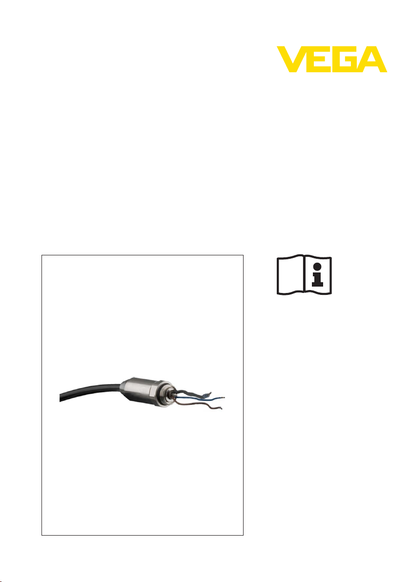
Connection cable IP 66/IP 68 (1 bar)
Retrofit set/Accessor
y for plics sensors
Document ID:
34107
Page 2

1 Contents
Contents
1 For yo
2 Product description
3 Mounting
4 Connecting
5 Annex
ur safety
1.1 Appropriate use . . . . . . . . . . . . . . . . . . . . . . . . . . . .
1.2 Impermissible use . . . . . . . . . . . . . . . . . . . . . . . . . .
1.3 General safety instructions . . . . . . . . . . . . . . . . . . . .
1.4 Safety instructions for Ex areas . . . . . . . . . . . . . . . . .
3.1 Mounting preparations . . . . . . . . . . . . . . . . . . . . . . .
3.2 Mounting steps. . . . . . . . . . . . . . . . . . . . . . . . . . . . .
4.1 Connection procedure. . . . . . . . . . . . . . . . . . . . . . . .
4.2 Wiring plan. . . . . . . . . . . . . . . . . . . . . . . . . . . . . . . .
5.1 Technical data . . . . . . . . . . . . . . . . . . . . . . . . . . . . .
5.2 Dimensions . . . . . . . . . . . . . . . . . . . . . . . . . . . . . . .
3
3
3
3
5
5
7
7
10
11
Editing status: 2012-05-18
2 Connection cable IP 66/IP 68 (1 bar) • Retrofit
34107-EN-120524
set/Accessory for plics sensors
Page 3

1 For your safety
1 For your safety
1.1 Appr
The connection cable is used to retrofit existing plics sensors to
achieve protection IP 66/IP 68 (1bar).
opriate use
1.2 Impermissible use
As a rule, the connection cable is not allowed to be used with four-wire
instruments. Four-wire instruments are sensors whose power supply
and measurement signal are transmitted over two separate pairs of
wires.
1.3 General safety instructions
The safety information in the operating instructions manual of the
respective sensor must be noted.
1.4 Safety instructions for Ex areas
Please note the Ex-specific safety information for installation and
operation in Ex areas. These safety instructions are part of the
operating instructions manual and come with the Ex-approved
instruments.
For instruments with Exd or StEx approval, the use of this connection
cable is not allowed.
34107-EN-120524
Connection cable IP 66/IP 68 (1 bar) • Retrofit
set/Accessory for plics sensors 3
Page 4

2 Product description
2 Product description
Sco
pe of delivery
Application area
scope of delivery encompasses:
The
l Connection cable with cable gland
l Blind stopper
l Documentation
- this operating instructions manual
The connection cable is suitable for the following plic s sensors with
aluminium or stainless steel housing:
l VEGAPULS series 60
l VEGAFLEX series 60 and 80
l VEGASON series 60
l VEGACAL series 60
l VEGABAR series 50 and 60
l VEGACAP series 60
l VEGASWING series 60
l VEGAWAVE series 60
To carry out the retrofit, the existing cable gland is removed and
replaced by the cable gland of the connection cable. The filter element
in the electronics housing is replaced by the blind stopper.
With VEGABAR, the measuring cell is then ventilated via the
capillaries in the connection cable.
4 Connection cable IP 66/IP 68 (1 bar) • Retrofit
34107-EN-120524
set/Accessory for plics sensors
Page 5

3 Mounting
1
2
3
3 Mounting
Tools
Blind stopper
3.1 Mounting
The following tools are required for mounting:
l Spanner SW 24 for unscrewing the cable gland
l Spanner SW 9 for unscrewing the filter element
l Screwdriver size 4 for screwing in the blind stopper
The blind stopper consists of adapter, O-ring and closing screw. It is
assembled according to the following drawing:
Fig. 1: Assembly of blind
1 Adapter
2 O-ring
3 Closing screw
preparations
stopper
3.2 Mounting steps
The illustration below shows the position of the cable gland and the
filter element in the respective housing:
34107-EN-120524
Connection cable IP 66/IP 68 (1 bar) • Retrofit
set/Accessory for plics sensors 5
Page 6

6
6
5
5
655
6
2
3 4
1
3 Mounting
Fig. 2: Position of the
versions
1 Stainless steel (electro-polished)
2 Stainless steel (precision casting)
3 Alu double chamber
4 Alu single chamber
5 Cable gland
6 Filter element
Proceed as follows for mounting:
1 Unscrew the existing cable gland
2 Screw in the cable gland of the IP 66/IP 68, 1 bar connection cable
3 Connect the wires according to chapter "Connect"
4 Unscrew the filter element (consisting of four parts)
5 Screw in the blind stopper
6 Lead the loose end of the connection cable into a suitable
connection box with pressure compensation, e.g. VEGABOX 02
6 Connection cable IP 66/IP 68 (1 bar) • Retrofit
cable gland and filter element with the different housing
34107-EN-120524
set/Accessory for plics sensors
Page 7

4 Connecting
2
4
3
1
3
2
3
1
3
4 Connecting
VEGABAR series 50 and
60
4.1 Connect
ion procedure
The electrical connection is carried out according to the operating
instructions manual of the respective sensor.
4.2 Wiring plan
Fig. 3: Wire assignment, connection cable
1 Brown (+) and
2 brown (+) and blue (-) to power supply or to the processing system
3 Shielding
4 Breather capillaries
Wire colour Terminal, electronics module
Brown 1
Blue 2
Black
blue (-) to the sensor
VEGAPULS, VEG
VEGA
CAL serie
ASO
s 60,
N,
VEGAFLEX series 60
and 80,
Fig. 4: Wire assignment, connection cable
1 Brown (+) and
2 brown (+) and blue (-) to power supply or to the processing system
3 Shielding
Wire colour Terminal, electronics module
Brown 1
Blue 2
34107-EN-120524
Connection cable IP 66/IP 68 (1 bar) • Retrofit
blue (-) to the sensor
set/Accessory for plics sensors 7
Page 8

2
3
1
3
2
3
1
3
4 Connecting
VEGACAP, VEGAVIB,
VEGASWIN
G series 60 -
Z-electronics
Wire colour Terminal, electronics module
Black
Fig. 5: Wire assignment, connection cable
1 Brown (+) and
2 brown (+) and blue (-) to power supply or to the processing system
3 Shielding
Wire colour Terminal, electronics module
Brown 1
Blue 2
Black
blue (-) to the sensor
VEGACAP, VEGAVIB,
VEGASWIN
G series 60 -
T-electronics
Fig. 6: Wire assignment, connection cable
to the sensor
1 Brown, blue, white, yellow
2 Brown, blue, white, yellow to voltage supply or to the processing system
3 Shielding
Wire colour Terminal, electronics module
Brown 1
Blue 4
White 2
Yellow 3
8 Connection cable IP 66/IP 68 (1 bar) • Retrofit
34107-EN-120524
set/Accessory for plics sensors
Page 9

4 Connecting
Wire colour Terminal, electronics module
Black
34107-EN-120524
Connection cable IP 66/IP 68 (1 bar) • Retrofit
set/Accessory for plics sensors 9
Page 10

5 Annex
5 Annex
5.1 Technical da
Mechanical data
Structure four wires, one steel cable, one breather
Standard lengths 5 m (16.4 ft), 6 m (19.69 ft), 10 m (32.81 ft),
Min. bending radius at 25 °C/77 °F 25 mm (0.985 in)
Diameter approx. 8 mm (0.315 in)
Torque of the cable gland max. 5 Nm
Materials
Connection cable PE (colour black or blue), PUR (colour blue)
Cable gland 316L
Seal FKM (Viton)
Closing screw 316L
Temperature range
PE cable -20 … +60 °C (-4 … +140 °F)
PUR cable -20 … +80 °C (-4 … +176 °F)
Electrical data
Wire cross-section 0.5 mm² (AWG 20)
Operating voltage 250 V AC
Insulation group C according to VDE 0110
Test voltage outer jacket 5 kV eff./1 s
Protection rating
Sensor with connected cable IP 66/IP 68 (1 bar)
ta
capillary, screen braiding, metal foil, mantle
25 m (82.02 ft)
10 Connection cable IP 66/IP 68 (1 bar) • Retrofit
34107-EN-120524
set/Accessory for plics sensors
Page 11

5.2 Dimensions
70 mm (2
3
/
4
")
ø 24 mm
(
15
/
16
")
ø 8 mm
(
5
/
16
")
SW24
5 Annex
Fig. 7: Dimensions, cable gland connection
cable IP 68/IP 68 (1 bar)
34107-EN-120524
Connection cable IP 66/IP 68 (1 bar) • Retrofit
set/Accessory for plics sensors 11
Page 12

5 Annex
12 Connection cable IP 66/IP 68 (1 bar) • Retrofit
34107-EN-120524
set/Accessory for plics sensors
Page 13

5 Annex
34107-EN-120524
Connection cable IP 66/IP 68 (1 bar) • Retrofit
set/Accessory for plics sensors 13
Page 14

5 Annex
14 Connection cable IP 66/IP 68 (1 bar) • Retrofit
34107-EN-120524
set/Accessory for plics sensors
Page 15

5 Annex
34107-EN-120524
Connection cable IP 66/IP 68 (1 bar) • Retrofit
set/Accessory for plics sensors 15
Page 16

VEGA Grieshaber KG
ISO 9001
Am Hohenstein 113
77761 Schiltach
Germany
Phone +49 7836 50-0
Fax +49 7836 50-201
E-mail: info.de@vega.com
www.vega.com
Printing date:
All statements concerning scope of delivery, application,
practical use
and operating conditions of the sensors and
processing systems correspond to the information avail-
able at the time of printing.
© VEGA Grieshaber KG, Schiltach/Germany 2012
Subject to change without prior notice 34107-EN-120524
 Loading...