

Page 1
Ope
rating Instructions
VEGACONNECT 4 with connection
Interface converter USB - HART/I²C
box
Document ID:
32628
conditioning instruments
and communication
Sign
al
Page 2

Contents
Conten
1 About this document
2 For your safety
3 Product description
4 Connection
5 Connection examples
ts
1.1 Function. . . . . . . . . . . . . . . . . . . . . . . . . . . . . . . . . .
1.2 Target group . . . . . . . . . . . . . . . . . . . . . . . . . . . . . .
1.3 Symbolism used. . . . . . . . . . . . . . . . . . . . . . . . . . . .
2.1 Authorised personnel . . . . . . . . . . . . . . . . . . . . . . . .
2.2 Appropriate use . . . . . . . . . . . . . . . . . . . . . . . . . . . .
2.3 Warning about misuse . . . . . . . . . . . . . . . . . . . . . . .
2.4 General safety instructions . . . . . . . . . . . . . . . . . . . .
2.5 Safety label on the instrument . . . . . . . . . . . . . . . . . .
2.6 CE conformity . . . . . . . . . . . . . . . . . . . . . . . . . . . . .
2.7 Safety instructions for Ex areas . . . . . . . . . . . . . . . . .
2.8 Environmental instructions. . . . . . . . . . . . . . . . . . . . .
3.1 Configuration . . . . . . . . . . . . . . . . . . . . . . . . . . . . . .
3.2 Principle of operation . . . . . . . . . . . . . . . . . . . . . . . .
3.3 Operation. . . . . . . . . . . . . . . . . . . . . . . . . . . . . . . . .
3.4 Packaging, transport and storage . . . . . . . . . . . . . . .
4.1 Connection to the PC . . . . . . . . . . . . . . . . . . . . . . . .
4.2 Connection of the sensor/signal conditioning
instrument . . . . . . . . . . . . . . . . . . . . . . . . . . . . . . . .
5.1 Connection via I²C interface . . . . . . . . . . . . . . . . . . .
5.2 Connection via HART . . . . . . . . . . . . . . . . . . . . . . . .
3
3
3
4
4
4
4
5
5
5
5
6
7
8
8
9
10
13
15
2 VE
6 Setup
6.1 Operation. . . . . . . . . . . . . . . . . . . . . . . . . . . . . . . . .
7 Maintenance and fault rectification
7.1 Maintenance . . . . . . . . . . . . . . . . . . . . . . . . . . . . . .
7.2 Instrument repair . . . . . . . . . . . . . . . . . . . . . . . . . . .
8 Dismount
8.1 Dismounting steps . . . . . . . . . . . . . . . . . . . . . . . . . .
8.2 Disposal . . . . . . . . . . . . . . . . . . . . . . . . . . . . . . . . .
9 Supplement
9.1 Technical data . . . . . . . . . . . . . . . . . . . . . . . . . . . . .
9.2 Dimensions . . . . . . . . . . . . . . . . . . . . . . . . . . . . . . .
9.3 Industrial property rights . . . . . . . . . . . . . . . . . . . . . .
9.4 Trademark . . . . . . . . . . . . . . . . . . . . . . . . . . . . . . . .
GACONNECT 4 with connection box • Interface converter USB - HART/I²C
17
18
18
19
19
20
21
22
22
32628-EN-091118
Page 3
out this document
1 Ab
1 Abou
t this document
1.1 Function
This operating instructions manual provides all the information you
need for mounting, connection and setup as well as important
instructions for maintenance and fault rectification. Please read this
information before putting the instrument into operation and keep this
manual accessible in the immediate vicinity of the device.
1.2 Target group
This operating instructions manual is directed to trained qualified
personnel. The contents of this manual should be made available to
these personnel and put into practice by them.
1.3 Symbolism used
Inform
ation, tip, note
This symbol indicates helpful additional information.
Cauti
on: If this warning is ignored, faults or malfunctions can
result.
Warning: If this warning is ignored, injury to persons and/or serious
damage to the instrument can result.
Danger: If this warning is ignored, serious injury to persons and/or
destruction of the instrument can result.
applications
Ex
This symbol indicates special instructions for Ex applications.
32628-EN-091118
VEGACONNECT 4 with
l List
The dot set in front indicates a list with no implied sequence.
à Action
Th
is arrow indicates a single action.
1 Sequence
Numbers set in front indicate successive steps in a procedure.
connection box • Interface converter USB - HART/I²C 3
Page 4

2 For
your safety
or your safety
2 F
2.1 Authorised personnel
All operations described in this operating instructions manual must be
carried out only by trained specialist personnel authorised by the plant
operator.
During work on and with the device the required personal protective
equipment must always be worn.
2.2 Appropriate use
VEGACONNECT 4 is an interface converter for connecting a PC to
communication-capable VEGA instruments.
You can find detailed information on the application range in chapter
"Product description".
Operational reliability is ensured only if the instrument is properly used
according to the specifications in the operating instructions manual as
well as possible supplementary instructions.
For safety and warranty reasons, any invasive work on the device
beyond that described in the operating instructions manual may be
carried out only by personnel authorised by the manufacturer. Arbitrary
conversions or modifications are explicitly forbidden.
2.3 Warning about misuse
Inappropriate or incorrect us e of the instrument can give rise to
application-specific hazards, e.g. vessel overfill or damage to system
components through incorrect mounting or adjustment.
4 VE
2.4 General safety instructions
This is a high-tech instrument requiring the strict observance of
standard regulations and guidelines. The user must take note of the
safety instructions in this operating instructions manual, the countryspecific installation standards as well as all prevailing safety
regulations and accident prevention rules.
The instrument must only be operated in a technically flawless and
reliable condition. The operator is responsible for trouble-free
operation of the instrument.
During the entire duration of use, the user is obliged to determine the
compliance of the required occupational safety measures with the
current valid rules and regulations and also take note of new
regulations.
GACONNECT 4 with connection box • Interface converter USB - HART/I²C
32628-EN-091118
Page 5

2 For
your safety
2.5 Safety
The safety approval markings and safety tips on the device must be
observed.
label on the instrument
2.6 CE conformity
This device fulfills the legal requirements of the applicable EC
guidelines. By attaching the CE mark, VEGA provides a confirmation
of successful testing. You can find the CE conformity declaration in the
download area of
2.7 Safety
Please note the Ex-specific safety information for installation and
operation in Ex areas. These safety instructions are part of the
operating instructions manual and come with the Ex-approved
instruments.
www.vega.com.
instructions for Ex areas
2.8 Environmental instructions
Protection of the environment is one of our most important duties. That
is why we have introduced an environment management system with
the goal of continuously improving company environmental protection.
The environment management system is certified according to DIN
EN ISO 14001.
Please help us fulfil this obligation by observing the environmental
instructions in this manual:
l Chapter "Packaging, transport and storage"
l Chapter "Disposal"
32628-EN-091118
VEGACONNECT 4 with
connection box • Interface converter USB - HART/I²C 5
Page 6
4 5
6 7
2
1
3
OPEN
TWIST
USB
LOCK
3 Produc
t description
Scope of delivery
Components
3 Produc
t description
3.1 Configuration
The scope of delivery encompasses:
l VEGACONNECT 4 interface converter
l Connection box with two connection cables
l USB cable
l I²C adapter
l 2 x connection terminals
l Documentation
- this operating instructions manual
- Ex-specific "Safety instructions" (with Ex-versions)
- if necessary, further certificates
VEGACONNECT consists of the following components:
Type label
6 VE
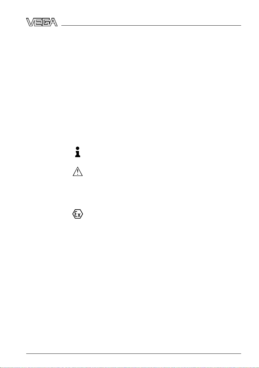
Fig. 1: Configuration VEGACONNECT
1 USB cable
2 VEGACONNECT 4
3 Connection
4 I²C bus cable
5 HART cable with 2 mm pins
6 I²C adapter for series 50 sensors
7 2 x terminals for cable with 2 mm pins
The type label contains the most important data for identification and
use of the instrument:
l Article number
l Serial number
GACONNECT 4 with connection box • Interface converter USB - HART/I²C
box with storage space
32628-EN-091118
Page 7

t description
hnical data
l Tec
l Article numbers, documentation
3 Produc
The serial number allows you to access the delivery data of the
instrument via
www.vega.com, "VEGA Tools" and "serial number
search".
3.2 Principle of operation
Application area
Functional principle
VEGACONNECT 4 is an interface converter for connection of
communication-capable VEGA instruments to the USB interface of a
PC. It can also be used as a universal HART modem for sensors from
other manufacturers. An adjustment software such as PACTware with
VEGA DTMs is required for parameter adjustment of these instruments.
VEGACONNECT 4 can be connected to the following VEGA instruments. All currently available electronics versions are supported
(HART, Profibus PA, Foundation Fieldbus). When instruments from
®
the plics
series are used, VEGACONNECT 4 can be inserted directly
into the respective instrument.
l VEGAPULS radar sensors
l VEGASON ultrasonic sensors
l VEGAFLEX guided microwave
l VEGABAR process pressure transmitter
l Pressure transmitter D series
l Capacitive electrode EL/EK
l VEGADIS indicating instruments
l VEGAMET signal conditioning instruments
l Wireless Gateways PLICSRADIO
Connection cable, adapter and terminals for connection to the different
instrument series are attached to all VEGACONNECT 4. These
adapters can be kept in the storage space of the connection box.
The VEGACONNECT 4 interface converter is connected via the USB
connection to a PC. It converts the signals and protocols of the USB
interface into the corresponding signal/protocol of the connected
instrument. The following systems are supported:
Power supply
32628-EN-091118
VEGACONNECT 4 with
l 4 … 20 mA with superimposed HART protocol
l Profibus PA via I²C protocol
l Foundation Fieldbus via I²C protocol
Voltage supply of VEGACONNECT 4 is provided via the USB interface
of the PC.
Detailed information about the power supply can be found in chapter
"Technical data".
connection box • Interface converter USB - HART/I²C 7
Page 8

3 Produc
t description
Packaging
Transport
Transport inspection
Storage
Storage and transport
temperature
3.3 Operatio
n
The adjustment is carried out via a Windows PC with a parameter
adjustment software such as PACTware with respective DTM. There
are no adjustment elements on the instrument itself.
3.4 Packaging, transport and storage
Your instrument was protected by packaging during transport. Its
capacity to handle normal loads during transport is assured by a test
according to DIN EN 24180.
The packaging of standard instruments consists of environmentfriendly, recyclable cardboard. For special versions, PE foam or PE foil
is also used. Dispose of the packaging material via specialised
recycling companies.
Transport must be carried out under consideration of the notes on the
transport packaging. Nonobservance of these instructions can cause
damage to the device.
The delivery must be checked for completeness and possible transit
damage immediately at receipt. Ascertained transit damage or
concealed defects must be appropriately dealt with.
Up to the time of installation, the packages must be left closed and
stored according to the orientation and storage markings on the
outside.
Unless otherwise indicated, the packages must be stored only under
the following conditions:
l Not in the open
l Dry and dust free
l Not exposed to corrosive media
l Protected against solar radiation
l Avoiding mechanical shock and vibration
l Storage and transport temperature see chapter "Supplement -
Technical data - Ambient conditions"
l Relative humidity 20 … 85 %
8 VE
32628-EN-091118
GACONNECT 4 with connection box • Interface converter USB - HART/I²C
Page 9

4 Conn
ection
Connection
Driver
4 Conn
ection
4.1 Connection to the PC
Note:
First of all you should install the driver before connecting VEGACONNECT 4 to the PC.
An USB interface (1.1 or 2.0) is compulsory for connection of
VEGACONNECT 4 to a PC. The connection is provided with the
supplied USB cable. Voltage supply of VEGACONNECT 4 is provided
via the USB interface.
If
the supplied USB cable is replaced by another one, make sure that the
insulation thickness of the cable is over 0.65 mm.
To operate VEGACONNECT 4, a suitable driver is required which is
included on the CD "DTM Collection". As an alternative, the software is
also available free-of-charge from our homepage. You should always
use the latest version to ensure the support of all instrument functions.
The system requirements for operation correspond to those of the
"DTM Collection" or of PACTware.
When installing the driver package "VEGA-DTM for Communication",
the suitable instrument driver is installed automatically. When
connecting VEGACONNECT 4, the driver installation is finished
automatically and is ready for operation without a restart.
32628-EN-091118
VEGACONNECT 4 with
connection box • Interface converter USB - HART/I²C 9
Page 10

2
1
3
OPEN
TWIST
USB
LOCK
4 Conn
ection
10 VE
Fig. 2: Electrical
1 USB 1.1 or 2.0 connection of the PC
2 USB connection cable (in the scope of delivery)
3 VEGACONNECT 4 with connection box
connection
4.2 Connection of the sensor/signal conditioning
instrument
VEGACONNECT 4 can be connected to virtually all communication-
capable VEGA instruments. With instruments of the plics
be mounted directly into the sensor. In this case, you can remove
VEGACONNECT 4 out of the connection box and insert it into the
®
plics
device instead of the indicating and adjustment module.
Connection to all instrument series can be provided without problems
via the supplied adapters.
®
series it can
GACONNECT 4 with connection box • Interface converter USB - HART/I²C
32628-EN-091118
Page 11

1 3
2
OPEN
TWIST
USB
LOCK
4 Conn
ection
Connection via I²C bus
Fig. 3: Connection
possibilities
Communication via I²C protocol
l Use of VEGACONNECT 4 in all plics
installation (see connection examples)
l For connection to the I²C (Com.) interface of all plics
®
sensors through direct
®
sensors,
connection 1
l For connection to the I²C interface instead of the adjustment
module MINICOM (VEGAPULS 40, 50, VEGAFLEX 50, VEGA-
SON 50 series), connection 2
Communication via HART protocol
l For connection to the 4 … 20 mA cable (an additional HART
resistor will be required depending on voltage supply/processing),
connection 3
hazardous Ex areas, the HART or I²C cable of VEGACONNECT 4
In
can be connected to an Ex approved sensor. VEGACONNECT 4 and
the PC must not be located in Ex area.
VEGACONNECT 4 can be connected to the I²C bus interface of the
following sensors.
l all sensors of plics
l VEGAPULS series 40, 50 from software version 4.00.00
l VEGASON series 50 from software version 4.00.00
l VEGAFLEX series 50 from software version 4.00.00
l VEGACAP from software version 1.10
l EL/EK (PA) with electronics module CAPE34
l VEGADIS 50/61
®
series
32628-EN-091118
VEGACONNECT 4 with
connection box • Interface converter USB - HART/I²C 11
Page 12

4 Conn
ection
Note:
e connection of Profibus PA or Foundation Fieldbus instruments is
Th
always carried out via the I²C interface on the sensor. A direct
connection of VEGACONNECT 4 on the Fieldbus is not possible.
Connection via HART
The connection via the sensor cable can be carried out on any HART
sensor. Depending on the processing system, an additional HART
resistor is required (see "Connection examples - Connection via
HART").
12 VE
32628-EN-091118
GACONNECT 4 with connection box • Interface converter USB - HART/I²C
Page 13

2
1
1
2
OPEN
TWIST
USB
LOCK
5 Conn
ection examples
Installation in plics
ries
5 Conn
ection examples
5.1 Connection via I²C interface
In hazardous Ex areas, the HART or I²C cable of VEGACONNECT 4
can be connected to an Ex approved sensor. VEGACONNECT 4 and
the PC must not be located in Ex area.
®
se-
Fig. 4: Installation
1 USB cable
2 plics
and connection in plics®device
®
device
External connection
®
plics
series
32628-EN-091118
VEGACONNECT 4 with
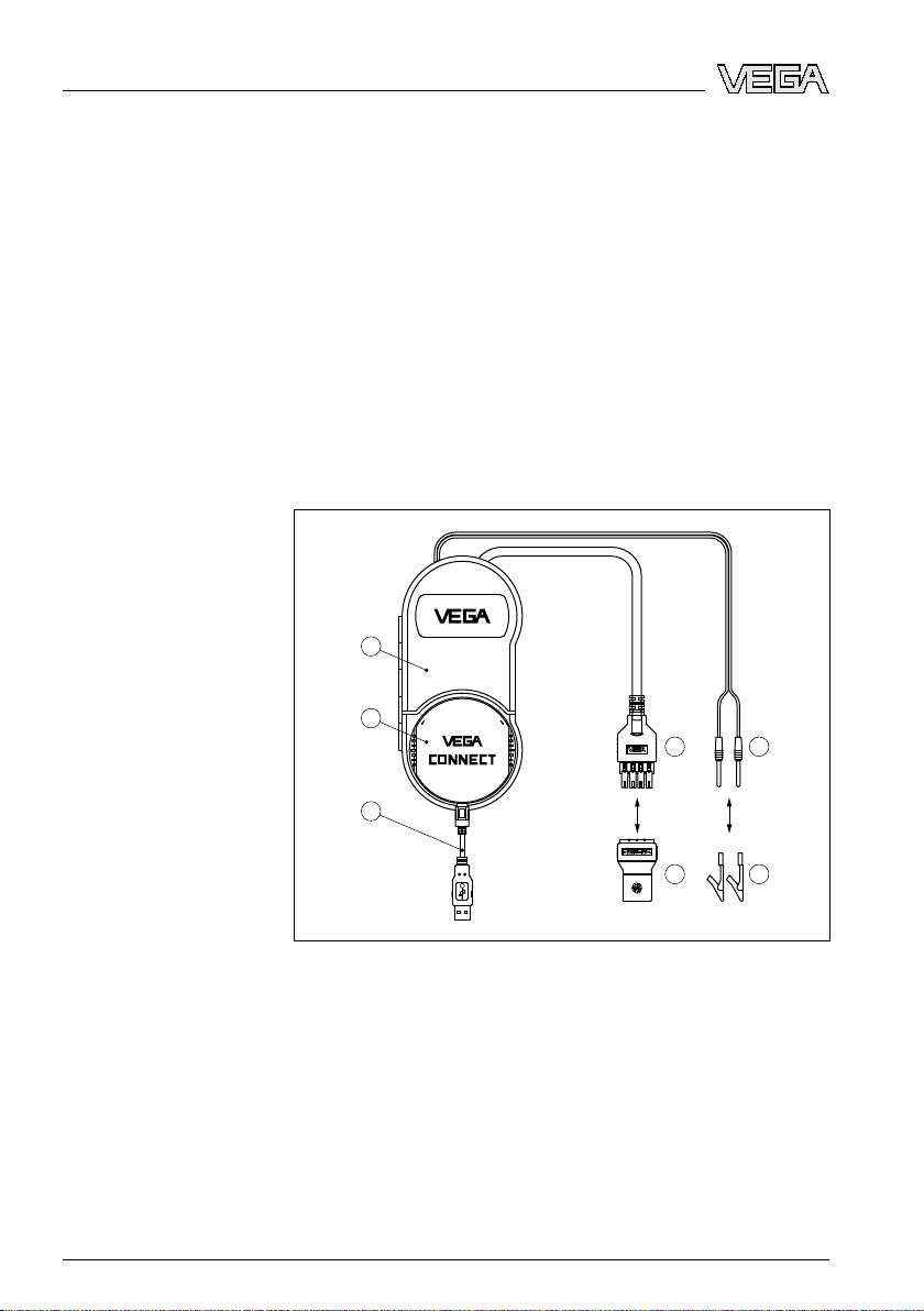
Fig. 5: Connection
1 I²C bus (Com.) interface
2 I²C connection cable
plics®series via I²C interface
connection box • Interface converter USB - HART/I²C 13
Page 14
OPEN
TWIST
USB
LOCK
1 2
OPEN
TWIST
USB
LOCK
3
1
2
ection examples
5 Conn
VEGADIS 61
VEGA series 50 sensors
Fig. 6: Connection VEGADIS 61 via I²C interface
1 I²C bus (Com.) interface
2 I²C connection
cable
If the sensors in the HART or Profibus system are connected with a
digital VEGADIS 61 indicating instrument, VEGACONNECT 4 can be
connected to the I²C bus interface of VEGADIS 61.
14 VE
Fig. 7: Connection
1 I²C bus (Com.) interface
2 I²C bus adapter for series 50
3 I²C connection cable
GACONNECT 4 with connection box • Interface converter USB - HART/I²C
series 50 via I²C interface
32628-EN-091118
Page 15

1
2
OPEN
TWIST
USB
LOC
K
VEGAMET 624/625,
VEGASCAN 693
ection examples
5 Conn
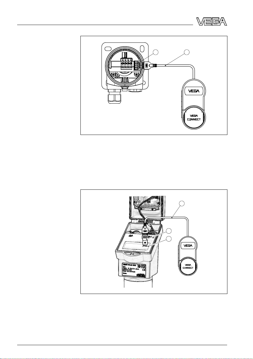
Fig. 8: Connection VEGAMET/VEGASCAN via I²C interface
1 I²C bus (Com.) interface
2 I²C connection
cable
Note:
Comm
unication with the sensor is carried out with VEGAMET 624/625
and VEGASCAN 693 also via the front I²C interface of the signal
conditioning instrument. The connection of VEGACONNECT 4 directly
to the 4 … 20 mA sensor cable is not possible.
HART communication
32628-EN-091118
VEGACONNECT 4 with
5.2 Connection via HART
If the resistance of the connected processing system is less than
230 Ω, the digital adjustment signal is extremely damped or shortcircuited. Digital communication with the PC is then no longer possible.
With low impedance processing systems, a resistance of approx.
230 Ω must be integrated into the 4 … 20 mA connection cable. The
connection can be either carried out in parallel to the sensor or via the
resistor.
Note:
connecting to a VEGAMET 381, VEGADIS 371 or VEGA-
When
TRENN 149 there is no additional HART resistor required. These
instruments have also connection sockets for direct connection of the
2 mm pins.
When using VEGAMET 624/625, VEGASCAN 693 signal conditioning
instruments, the connection cannot be carried out via the sensor cable.
The parameter adjustment of the signal conditioning instrument as well
as of the sensor can be carried out via the I²C connection sockets.
connection box • Interface converter USB - HART/I²C 15
Page 16

VEGAMET 381
on
1
2
1
2
%
1
3
2
OPEN
TWIST
USB
LOCK
1
2 4
3
OPEN
TWIST
USB
LOCK
ection examples
5 Conn
HART sensor with
VEGAMET 381
HART sensor on a PLC
16 VE
Fig. 9: Connection
plics®series via HART
1 HART sensor
2 Connection cable with 2 mm pins
3 VEGAMET 381 or VEGADIS 371
Fig. 10: Connection
plics®series via HART
1 HART sensor
2 HART resistance 230 Ω (optional depending on processing)
3 Connection cable with 2 mm pins and terminals
4 Processing system/PLC/Voltage supply
GACONNECT 4 with connection box • Interface converter USB - HART/I²C
32628-EN-091118
Page 17

6 Setup
6 Setup
6.1 Operatio
Use and adjustment are described in the operating instructions manual
as well as in the online help of PACTware and the VEGA-DTMs as well
as in the respective device instructions manual.
Informa
tion:
You find the VEGACONNECT 4 DTM in the device catalogue under
the group "Driver". When adding a HART sensors, the window
"Channel selection" appears in addition in which you have to select the
connection (connection via HART or I²C).
n
32628-EN-091118
VEGACONNECT 4 with
connection box • Interface converter USB - HART/I²C 17
Page 18

aintenance and fault rectification
7 M
7 Maint
enance and fault rectification
7.1 Maintenance
When used as directed in normal operation, VEGACONNECT 4 is
completely maintenance free.
7.2 Instrument repair
If a repair is necessary, please proceed as follows:
You can download a return form (23 KB) from our Internet homepage
www.vega.com
form".
By doing this you help us carry out the repair quickly and without
having to call back for needed information.
l Print and fill out one form per instrument
l Clean the instrument and pack it damage-proof
l Attach the completed form and, if need be, also a safety data
sheet outside on the packaging
l Please ask the agency serving you for the address of your return
shipment. You can find the respective agency on our website
www.vega.com
under: "Downloads - Forms and certificates - Repair
under: "Company - VEGA worldwide"
18 VE
32628-EN-091118
GACONNECT 4 with connection box • Interface converter USB - HART/I²C
Page 19

8 Dismount
8 Dismou
nt
8.1 Dismounting steps
Since VEGACONNECT 4 is a mobile instrument, it is not necessary to
take note of separate dismounting steps.
8.2 Disposal
The instrument consists of materials which can be recycled by
specialised recycling companies. We use recyclable materials and
have designed the electronics to be easily separable.
WEEE directive 2002/96/EG
This instrument is not subject to the WEEE directive 2002/96/EG and
the respective national laws. Pass the instrument directly on to a
specialised recycling company and do not use the municipal collecting
points. These may be used only for privately used products according
to the WEEE directive.
Correct disposal avoids negative effects to persons and environment
and ensures recycling of useful raw materials.
Materials: see chapter "Technical data"
If you have no possibility to dispose of the old instrument
professionally, please contact us concerning return and disposal.
32628-EN-091118
VEGACONNECT 4 with
connection box • Interface converter USB - HART/I²C 19
Page 20

9 Suppl
ement
9 Supp
lement
9.1 Technical data
Electrical data
Voltage supply from USB interface 5 V
Max. power consumption 500 mW
Galvanic separation between l HART - USB
Ambient conditions
Permissible ambient temperature -20 … +60 °C (-4 … +140 °F)
Storage and transport temperature -40 … +70 °C (-40 … +158 °F)
Electrical protective measures
Protection rating IP 40
Connection cable
USB cable for connection to the USB interface of the PC
I²C bus cable for connection to I²C bus interface
Cable with 2 mm pins for connection to CONNECT sockets
Cable lengths
- USB cable 150 cm (59.055 in)
- I²C bus cable 150 cm (59.055 in)
- Cable with 2 mm pins 150 cm (59.055 in)
l I²C-Bus - USB
Material, dimensions, weight
Housing material impact-resistant plastic (ABS)
Housing dimensions (LxBxH) 160x80x51 mm (6.299x3.15x2.008 in)
Weight with connection cables 325 g (0.716 lbs)
Approvals
Depending on the version, instruments with approvals can have different technical data.
For these instruments, the corresponding approval documents have to be taken into account.
These are part of the delivery or can be downloaded under
"serial number search" as well as via "Downloads" and "Approvals".
20 VE
GACONNECT 4 with connection box • Interface converter USB - HART/I²C
www.vega.com
via "VEGA Tools" and
32628-EN-091118
Page 21

imensions
162mm (6.38") 52 mm
(2.05")
80mm (3.15")
9.2 D
Fig. 12: Dimensions VEGACONNECT 4
9 Sup
plement
32628-EN-091118
VEGACONNECT 4 with
connection box • Interface converter USB - HART/I²C 21
Page 22

9 Suppl
ement
9.3 Indus
VEGA product lines are global protected by industrial property rights.
Further information see http://www.vega.com.
Only in U.S.A.: Further information see patent label at the sensor
housing.
VEGA Produktfamilien sind weltweit geschützt durch gewerbliche
Schutzrechte.
Nähere Informationen unter http://www.vega.com.
Les lignes de produits VEGA sont globalement protégées par des
droits de propriété intellectuelle.
Pour plus d'informations, on pourra se référer au site http://www.vega.
com.
VEGA lineas de productos están protegidas por los derechos en el
campo de la propiedad industrial.
Para mayor información revise la pagina web http://www.vega.com.
Линии продукции фирмы ВЕГА защищаются по всему миру
правами на интеллектуальную собственность.
Дальнейшую информацию смотрите на сайте http://www.vega.com.
VEGA系列产品在全球享有知识产权保护。
进一步信息请参见网站<http://www.vega.com>。
trial property rights
9.4 Trademark
All the brands as well as trade and company names used are property
of their lawful proprietor/originator.
22 VE
32628-EN-091118
GACONNECT 4 with connection box • Interface converter USB - HART/I²C
Page 23

INDEX
4
4 … 20 mA 7
C
Connection 12
D
Driver 9
DTM 7, 17
DTM Collection 9
F
Foundation Fieldbus 7, 12
H
HART 7
- Modem 7
- Resistor 11-12, 15
I
I²C interface 11
Interface converter 7
O
Online help 17
dex
In
P
PACTware 7, 17
PLC 16
plics® 10
Power supply 7, 9
Profibus PA 7, 12
R
Repair form 18
S
Safety data sheet 18
Serial number 7
T
Type label 6
U
USB 9
32628-EN-091118
VEGACONNECT 4 with
connection box • Interface converter USB - HART/I²C 23
Page 24

VEGA Grieshaber KG
ISO 9001
Am Hohenstein 113
77761 Schiltach
Germany
Phone +49 7836 50-0
Fax +49 7836 50-201
E-mail: info@de.vega.com
www.vega.com
Printing date:
statements concerning scope of delivery, application,
All
practical use and operating conditions of the sensors and
processing systems correspond to the information avail-
able at the time of printing.
© VEGA Grieshaber KG, Schiltach/Germany 2009
Subject to change without prior notice 32628-EN-091118
 Loading...