

Page 1

Operating Instructions
VEGACONNECT 3
Signal conditioning instruments
and communication
in
out
Page 2

Contents
1 About this document
1.1 Function . . .
. . . . . . . . . . . . . . . . . . . . . . . . . .
4
1.2 Target group . . . . . . . . . . . . . . . . . . . . . . . . . .
4
1.3 Symbolism used . . . . . . . . . . . . . . . . . . . . . . .
4
2 For your safety
2.1 Authorised personnel . . . . . . . . . . . . . . . . . . . .
5
2.2 Appropriate use. . . . . . . . . . . . . . . . . . . . . . . .
5
2.3 Warning about misuse . . . . . . . . . . . . . . . . . . .
5
2.4 General safety instructions . . . . . . . . . . . . . . . .
5
2.5 Safety approval markings and safety tips . . . . .
6
2.6 CE conformity . . . . . . . . . . . . . . . . . . . . . . . . .
6
2.7 Safety instructions for Ex areas . . . . . . . . . . . .
6
2.8 Environmental instructions . . . . . . . . . . . . . . . .
6
3 Product description
3.1 Configuration. . . . . . . . . . . . . . . . . . . . . . . . . .
7
3.2 Principle of operation . . . . . . . . . . . . . . . . . . . .
8
3.3 Operation . . . . . . . . . . . . . . . . . . . . . . . . . . . .
9
3.4 Packaging, transport and storage . . . . . . . . . . .
9
4 Connection
4.1 Connection to PC/Modem . . . . . . . . . . . . . . . .
11
4.2 Connection of the sensor/signal conditioning
instrument. . . . . . . . . . . . . . . . . . . . . . . . . . . .
12
5 Connection examples
5.1 Connection via I²C interface . . . . . . . . . . . . . . .
15
5.2 Connection via HART . . . . . . . . . . . . . . . . . . .
17
5.3 Connection via VBUS . . . . . . . . . . . . . . . . . . .
19
6 Maintenance and fault rectification
6.1 Maintenance . . . . . . . . . . . . . . . . . . . . . . . . . .
20
6.2 Instrument repair . . . . . . . . . . . . . . . . . . . . . . .
20
7 Dismounting
7.1 Dismounting steps . . . . . . . . . . . . . . . . . . . . . .
21
7.2 Disposal . . . . . . . . . . . . . . . . . . . . . . . . . . . . .
21
8 Supplement
8.1 Technical data. . . . . . . . . . . . . . . . . . . . . . . . .
22
8.2 Industrial property rights. . . . . . . . . . . . . . . . . .
23
8.3 Trademark . . . . . . . . . . . . . . . . . . . . . . . . . . .
23
2 VEGACONNECT 3
Contents
25641-EN-070726
Page 3
1 About this document
1.1 Function
This operating instructions
manual provides all the information
you need for mounting, connection and setup as well as
important instructions for maintenance and fault rectification.
Please read this information before putting the instrument into
operation and keep this manual accessible in the immediate
vicinity of the device.
1.2 Target group
This operating instructions manual is directed to trained
personnel. The contents of this manual should be made
available to these personnel and put into practice by them.
1.3 Symbolism used
Information, tip, note
This symbol indicates helpful additional information.
Caution: If this warning is ignored, faults or malfunc-
tions can result.
Warning: If this warning is ignored, injury to persons and/or
serious damage to the instrument can result.
Danger: If this warning is ignored, serious injury to persons
and/or destruction of the instrument can result.
Ex applications
This symbol indicates special instructions for Ex applications.
l List
The dot set in
front indicates a list with no implied sequence.
à Action
This arrow indicates a
single action.
1 Sequence
Numbers set in front indicate successive steps in a procedure.
VEGACONNECT 3 3
About this document
25641-EN-070726
Page 4

2 For your safety
2.1 Authorised personnel
All operations descr
ibed in this operating instructions manual
must be carried out only by trained specialist personnel
authorised by the operator.
During work on and with the device the required personal
protection equipment must always be worn.
2.2 Appropriate use
VEGACONNECT 3 is an interface converter for connecting a
PC or modem to communication-capable VEGA instruments.
You can find detailed information on the application range in
chapter "Product description".
Operational reliability is ensured only if the instrument is
properly used according to the specifications in the operating
instructions manual as well as possible supplementary
instructions.
Due to safety and warranty reasons, any invasive work on the
device beyond that described in the operating instructions
manual may be carried out only by personnel authorised by the
manufacturer. Arbitrary conversions or modifications are
explicitly forbidden.
2.3 Warning about misuse
Inappropriate or incorrect use of the instrument can give rise to
application-specific hazards, e.g. vessel overfill or damage to
system components through incorrect mounting or adjustment.
2.4 General safety instructions
This is a high-tech instrument requiring the strict observance of
standard regulations and guidelines. The user must take note
of the safety instructions in this operating instructions manual,
the country-specific installation standards as well as all
prevailing safety regulations and accident prevention rules.
The instrument must only be operated in a technically flawless
and reliable condition. The operator is responsible for troublefree operation of the instrument.
4 VEGACONNECT 3
For your safety
25641-EN-070726
Page 5

During the entire duration of use, the user is obliged to
determine the compliance of the required occupational safety
measures with the current valid rules and regulations and also
take note of new regulations.
2.5 Safety approval markings and safety tips
The safety approval markings and safety tips on the device
must be observed.
2.6 CE conformity
The protection goals of the EMC Directive 2004/108/EC (EMC)
and the Low Voltage Directive 2006/95/EC (LVD) are fulfilled.
Conformity has been judged according to the following
standards:
EMC: EN 61326: 1997
(electrical instruments for control technology and laboratory
use - EMC requirements)
l Emission: Class A
l Susceptibil
ity: Industrial
areas
LVD: EN 61010-1: 1993
(safety regulatio
ns for electrical measurement, control and
laboratory instruments - part 1: Gerneral requirements)
2.7 Safety instructions for Ex areas
Please note the Ex-specific safety information for installation
and operation in Ex areas. These safety instructions are part of
the operating instructions manual and come with the Exapproved instruments.
2.8 Environmental instructions
Protection of the environment is one of our most important
duties. That is why we have introduced an environment
management system with the goal of continuously improving
company environmental protection. The environment management system is certified according to DIN EN ISO 14001.
Please help us fulfil this obligation by observing the environmental instructions in this manual:
l Chapter "Packaging, transport
and storage"
l Chapter "Disposal"
VEGACONNECT 3 5
For your safety
25641-EN-070726
Page 6
3 Product description
3.1 Configuration
The scope
of delivery encompasses:
l VEGACONNECT 3 interface converter
l I²C adapter
l HART adapter
l 2x
terminals for HART adapter
l Documentation
- this operating instructions manual
- Ex specific safety instructions (with Ex versions), if
necessary further certificates
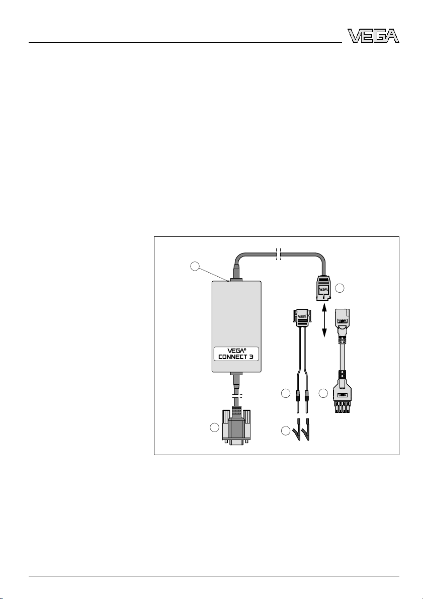
VEGACONNECT 3 consists of the following components:
3
5
6
4
1
2
Fig. 1: VEGACONNECT 3
1 Socket for external voltage supply
2 RS232 interface
3 I²C connection for series 40/50
4 I²C adapter for plics
®
series
5 HART adapter
6 2x terminals for HART adapter
Scope of delivery
Components
6 VEGACONNECT 3
Product description
25641-EN-070726
Page 7

3.2 Principle of operation
VEGACONNECT 3 is an interface converter for connecting
communication-capable VEGA instruments to the RS232
interface of a PC or modem. It can be also used as universal
HART modem for sensors of other manufacturers. For
parameter adjustment of these instruments, an adjustment
software such as PACTware™ with VEGA DTM or VEGA
Visual Operating (VVO) is required. The Visual VEGA software
can be used for remote enquiry of measured values.
VEGACONNECT 3 can be connected to the VEGA instruments listed below. All currently available protocol versions are
supported. These are: HART, Profibus PA, Foundation
Fieldbus, VBUS (optional).
l VEGAPULS radar
sensors
l VEGASON ultrasonic sensors
l VEGAFLEX guided microwave
l VEGABAR process pressure
transmitter
l Pressure transmitter D series
l Capacitive electrode EL/EK
l VEGADIS indicating instruments
l VEGAMET signal conditioning
instruments
VEGACONNECT 3 is available in two versions:
l CONNECT3.X: Standard version without VBUS int
erface
l CONNECT3.V: Version with additional VBUS interface
Two adapters and terminals for connection to different instrument series are attached to each VEGACONNECT 3.
The VEGACONNECT 3 interface converter is connected via
an RS232 connection to a PC or an external modem. It
converts the signals and protocols of the RS232 interface into
the corresponding signal/protocol of the connected instrument.
The following systems are supported:
l 4 … 20 mA with
superimposed HART protocol
l Profibus PA via I²C protocol
l Foundation Fieldbus
via I²C protocol
l VBUS (only with the opt
ion additional VBUS interface)
Power supply is provided via the control cables of the RS232
interface of the PC or modem. In a few cases, it may happen
that the gauges of the control cables are not sufficient for
power supply of VEGACONNECT 3. In this case, power
supply can be carried out via a standard, separate power
supply unit (e.g. Friwo EP1). A protective low voltage in the
Area of application
Functional principle
Supply
VEGACONNECT 3 7
Product description
25641-EN-070726
Page 8

range of 6 … 12 V DC is not necessary. The power supply unit
is connected with a low voltage micro plug (outer ø 3.5 mm,
inner ø 1.3 mm) to VEGACONNECT 3. The polarity is
unimportant.
You can find detailed specifications on voltage supply in
chapter "Technical data" in the "Supplement".
3.3 Operation
The adjustment is carried out via a Windows PC with a
parameter adjustment software such as PACTware™ with
VEGA DTM or VVO. There are no adjustment elements on the
instrument itself.
3.4 Packaging, transport and storage
Your instrument was protected by packaging during transport.
Its capacity to handle normal loads during transport is assured
by a test according to DIN EN 24180.
The packaging of standard instruments consists of environ-
ment-friendly, recyclable cardboard. For special versions, PE
foam or PE foil is also used. Dispose of the packaging material
via specialised recycling companies.
Transport must be carried out under consideration of the notes
on the transport packaging. Nonobservance of these instructions can cause damage to the device.
The delivery must be checked for completeness and possible
transit damage immediately at receipt. Ascertained transit
damage or concealed defects must be appropriately dealt
with.
Up to the time of installation, the packages must be left closed
and stored according to the orientation and storage markings
on the outside.
Unless otherwise indicated, the packages must be stored only
under the following conditions:
l Not
in the open
l Dry and dust free
l Not exposed to corrosive media
l Protected against
solar radiation
l Avoiding mechanical shock and vibration
Packag
ing
Tr
ansp
ort
Transport inspection
Storage
8 VEGACONNECT 3
Product description
25641-EN-070726
Page 9

l Storage and transport temperature see "Supplement -
Technical data - Ambient conditions"
l Relative humidity 20 … 85 %
Storage and
transport tem-
perature
VEGACONNECT 3 9
Product description
25641-EN-070726
Page 10

4 Connection
4.1 Connection to P
C/Modem
For connection of VEGACONNECT 3 to a PC or a modem, an
RS232 interface is absolutely necessary. If your PC has no
RS232 interface, you can use an USB-RS232 adapter (order
number 2.26900). The voltage supply of VEGACONNECT 3 is
carried out via the control cables of the RS232 interface. If
these do not deliver suffiencient power, an additional power
supply unit can be used (see chapter "Configuration - Power
supply").
VEGACONNECT 3 can be connected with the 9-pole Sub-D
plug directly to the RS232 interface of any PC.
5
4
3
2
1
9
8
7
6
3
2
1
45
Fig. 2: Electrical connection
1 RS232 connection (9-pole Sub-D socket)
2 to PC/Modem
3 to the sensor (I²C-Bus plug series 50)
4 to the 4 … 20 mA signal cable
5 to the sensor (I²C-Bus plug plics
®
series)
If VEGACONNECT 3 should be connected with the RS232
interface of an external modem, a special modem connection
cable must be used in addition. The cable is available from
VEGA under the order number "MODEM.KX". Alternatively,
Connection to the PC
Connection to a modem
10 VEGACONNECT 3
Connection
25641-EN-070726
Page 11

you can make one yourself according to the below pin
assignments. Keep in mind that this is not a standard null
modem cable.
DCD
RxD
TxD
DTR
GND
DSR
RTS
CTS
RI
1
2
3
4
5
6
7
8
9
1
2
3
4
5
6
7
8
9
Signal Pin Pin
Fig. 3: Assignment modem connection cable
The modem connection cable supplied by VEGA has a 9-pole
plug connector for modems with 9-pole socket as well as an
adapter 9/25-pole for modems with 25-pole connection.
4.2 Connection of the sensor/signal conditioning
instrument
VEGACONNECT 3 can be connected to all communication-
capable VEGA instruments. Because there are many different
instrument series and protocol versions, the connection
possibilities are manifold. The supplied adapter enables
connection to each instrument.
VEGACONNECT 3 11
Connection
25641-EN-070726
Page 12

1
2
3
Fig. 4: Connection possibilities
Communication via HART protocol
l For connection to the 4 … 20 mA cable (an additional
HART resistor will be required depending on voltage
supply/processing), connection 2
l For
connection to the 2 mm sockets (VEGAPULS 40, 50,
VEGAFLEX 50, VEGAS
ON 50 series), (connection 2)
Communication via I²C protocol
l For connection to the I²C (Com.) interface of all plics
®
sensors (connection 3)
l For connection to the I²C interface instead of the adjust-
ment module MINICOM (VEGAPULS 40, 50, VEGAFLEX
50, VEGASON 50 series), connection 1
Communication via VBUS protocol
l For
connection to the two-wire cable of
all VBUS sensors
(connection 2)
l For connection to the 2 mm sockets of all VBUS sensors
(connection 2)
VEGACONNECT 3 can be connected to the I²C bus interface
of the following sensors.
l VEGAPULS series 40, 50 from software version 4.00.00
l VEGASON series 50 from software
version 4.00.00
l VEGAFLEX series 50 from
software version 4.00.00
l VEGACAP from software
version 1.10
l EL/EK (PA) with
oscillator CAPE34
Connection
via I²C bus
12 VEGACONNECT 3
Connection
25641-EN-070726
Page 13

l VEGADIS 50
l All sensors of plics
®
series (via I²C adapter)
Note:
The connection of Profibus PA or Foundation Fieldbus (FF)
instruments is always carried out via the I²C interface directly
on the VEGA sensor. The Profibus or FF protocols are not
supported by VEGACONNECT 3. For that reason, direct
connection to the Fieldbus is not possible.
Connection to the sensor
l The I²C bus
plug is connec
ted to the I²C bus interface on
the sensor
l The pins are connected to the CONNECT sockets on the
sensor
Connection to the HART signal cable
l The pin terminals are connected to the 4 … 20 mA signal
cable
Connection
to VBUS signal conditioning instruments
l The pins are connected to the CONNECT sockets on
the
signal conditioning instrument (only version with integrated
VBUS interface, CONNECT3.V)
PA and Foundation Fieldbus sensors
l The I²C bus
plug is connec
ted to the I²C bus interface on
the sensor
In hazardous Ex areas, the bus cable of VEGACONNECT 3
can be connected to an Ex approved sensor. VEGACONNECT 3 and the PC must not be located in Ex area.
Connection via HART/VBUS
VEGACONNECT 3 13
Connection
25641-EN-070726
Page 14

5 Connection examples
5.1 Connection via I²C inte
rface
1 2
3
Fig. 5: Connection plics®series via I²C interface
1 I²C bus (Com.) interface
2 I²C adapter for plics
®
series
3 RS232 connection
3
1
2
Fig. 6: Connection series 50 via I²C interface
1 RS232 connection
2 I²C bus plug
3 I²C bus interface
VEGA plics
®
series
VEGA series 50 sensors
14 VEGACONNECT 3
Connection examples
25641-EN-070726
Page 15

2
1
3
Fig. 7: Connection VEGADIS 50 via I²C interface
1 RS232 connection
2 I²C bus plug
3 I²C bus interface
In conjunction with VEGACONNECT 3, VEGADIS 50 must not
be used in Ex area.
If the sensors in HART, VBUS or Profibus system are
connected with a digital VEGADIS 50 indicating instrument,
VEGACONNECT 3 can be connected to the I²C bus interface
of VEGADIS 50.
VEGADIS 50
VEGACONNECT 3 15
Connection examples
25641-EN-070726
Page 16

VEGACONNECT 3
2
3
1
Fig. 8: Connection VEGAMET/VEGASCAN via I²C interface
1 RS232 connection
2 I²C adapter for VEGACONNECT 3 (article no. 2.27323)
3 VEGACONNECT 3
Note:
Communication with the sensor is carried out with VEGAMET
624/625 and VEGASCAN 693 also via the front I²C interface of
the signal conditioning instrument. The connection of VEGA-
CONNECT 3 directly to the 4 … 20 mA sensor cable is not
possible.
5.2 Connection via HART
If the resistance of the connected processing system is less
than 230 Ohm, the digital adjustment signal is extremely
damped or short-circuited. Digital communication with the PC
is then no longer possible. With low impedance processing
systems, a resistance of approx. 230 Ohm must be integrated
into the 4 … 20 mA connection cable. The connection can be
either carried out in parallel to the sensor or via the resistor.
VEGAMET 624/625, VEGASCAN 693
HART communication
16 VEGACONNECT 3
Connection examples
25641-EN-070726
Page 17

4
21
3
Fig. 9: Connection plics®series via HART
1 Processing system/Voltage supply
2 HART resistance 230 Ohm (optional depending on the processing)
3 HART adapter
4 RS232 interface
1
2
4
3
Fig. 10: Connection series 50 via HART directly on the sensor
1 RS232 connection
2 I²C bus plug
3 HART adapter
4 CONNECT sockets
VEGA plics
®
series
VEGA series 50 sensors
VEGACONNECT 3 17
Connection examples
25641-EN-070726
Page 18

4
21
3
Fig. 11: Connection series 50 via HART
1 Processing system/Voltage supply
2 HART resistance 230 Ohm (optional depending on the processing)
3 HART adapter
4 RS232 connection
5.3 Connection via VBUS
6
5
7
4
1 2
3
VVO
Fig. 12: Connection via VBUS
1 Ex area
2 Non-Ex area
3 VEGAPULS 51VEx
4 VBUS
5 VEGATRENN 548VEx
6 VEGAMET 515V
7 VEGACONNECT 3
Note:
For connection to VBUS sensors, the version "VEGA-
CONNECT3.V: Version with additional VBUS interface" must
be available.
18 VEGACONNECT 3
Connection examples
25641-EN-070726
Page 19

6 Maintenance and fault rectification
6.1 Maintenance
When used as
directed in normal operation, VEGACONNECT
3 is completely maintenance free.
6.2 Instrument repair
If a repair is necessary, please proceed as follows:
You can download a return form (23 KB) from the Internet on
our homepage
www.vega.com under: "Downloads - Forms
and certificates - Repair form".
By doing this you help us carry out the repair quickly and
without having to call back for needed information.
l Print
and fill out one
form per instrument
l Clean the instrument and pack it damage-proof
l Attach the completed form and, if need be, also a safety
data sheet outside on the packaging
l Please ask the agency serving you for the address of your
return shipment. You can find
the respective agency on our
website www.vega.com under: "Company - VEGA world-
wide"
VEGACONNECT 3 19
Maintenance and fault rectification
25641-EN-070726
Page 20

7 Dismounting
7.1 Dismounting steps
Since VEGACONNECT 3 is a
mobile instrument, it is not
necessary to take note of separate dismounting steps.
7.2 Disposal
The instrument consists of materials which can be recycled by
specialised recycling companies. We use recyclable materials
and have designed the electronics to be easily separable.
WEEE directive 2002/96/EG
This instrument is not subject to the WEEE directive 2002/96/
EG and the respective national laws (in Germany, e.g.
ElektroG). Pass the instrument directly on to a specialised
recycling company and do not use the municipal collecting
points. These may be used only for privately used products
according to the WEEE directive.
Correct disposal avoids negative effects to persons and
environment and ensures recycling of useful raw materials.
Materials: see chapter "Technical data"
If you cannot dispose of the instrument properly, please
contact us about disposal methods or return.
20 VEGACONNECT 3
Dismounting
25641-EN-070726
Page 21

8 Supplement
8.1 Technical data
Electri
cal data
Voltage supply
- Control cables of the RS232 inter-
face
(5 … 15 V)
- optional power supply unit with
protective low voltage (VDE 0100,
part 410) and low volt micro plug
(outer-ø 3.5 mm, inner-ø 1.3 mm)
(6 … 12 V DC, min. 10 mA)
Power consumption max. 50 mW
Galvanic separation between l VBUS and RS232
l HART and RS232
l I²C bus and RS232
Ambient
conditions
Permissible
ambient temperature -20 … +60 °C (-4 … +140 °F)
Storage and transport temperature -40 … +70 °C (-40 … +158 °F)
Electrical protective measures
Protection IP 20
Connection cable
I²C bus plug for connection to I²C bus interface
Pins for connection to CONNECT sockets
Terminals on the pins for connection to 4 … 20 mA/HART or VBUS
signal cable
Cable lengths
- RS232 cable approx. 30 cm (11.81 in)
- Cable on the bus side approx. 200 cm (78.74 in)
Material, dimensions, weight
Housing material impact-proof plastic (ABS), light gray
Housing dimensions LxWxH = 120x60x40 mm (4.72x2.36x1.57 in)
Weight with connection cables approx. 200 g (0.441 lbs)
Approvals
Flame proofing ATEX II (1) GD [EEx ia] IIC
VEGACONNECT 3 21
Supplement
25641-EN-070726
Page 22

8.2 Industrial property rights
VEGA product lines are global protected by industrial property rights.
Further information see http://www.vega.com.
Only in U.S.A.: Further information see patent label at the sensor housing.
VEGA Produktfamilien sind weltweit geschützt durch gewerbliche Schutzrechte.
Nähere Informationen unter http://www.vega.com.
Les lignes de produits VEGA sont globalement protégées par des droits de
propriété intellectuelle.
Pour plus d'informations, on pourra se référer au site http://www.vega.com.
VEGA lineas de productos están protegidas por los derechos en el campo de la
propiedad industrial.
Para mayor información revise la pagina web http://www.vega.com.
Линии продукции фирмы ВЕГА защищаются по всему миру правами на
интеллектуальную собственность.
Дальнейшую информацию смотрите на сайте http://www.vega.com.
VEGA系列产品在全球享有知识产权保护。
进一步信息请参见网站<http://www.vega.com>。
8.3 Trademark
All brands used as well as trade and company names are
property of their lawful proprietor/originator.
22 VEGACONNECT 3
Supplement
25641-EN-070726
Page 23

VEGACONNECT 3 23
Supplement
25641-EN-070726
Page 24

VEGA Grieshaber KG
Am Hohenstein 113
77761 Schiltach
Germany
Phone +49 7836 50-0
Fax +49 7836 50-201
E-mail: info@de.vega.com
www.vega.com
ISO 9001
All statements concerning scope of delivery, application,
practical use and operating conditions of the sensors and
processing systems correspond to the information avail-
able at the time of printing.
© VEGA Grieshaber KG, Schiltach/Germany 2007
Subject to change without prior notice 25641-EN-070726
 Loading...