

Page 1
Operating Instruction
;;;
VEGACONNECT 2
Level and Pressure
;
VEGACONNECT2
out
in
Page 2
Operating instruction
1 Product description
1.1 Function and configuration
VEGACONNECT 2 is an interface cable
(interface adapter) between communication
capable VEGA-instruments (VEGASON,
VEGAPULS, D-series, VEGABAR,
VEGAMET) and a PC in conjunction with the
adjustment software VEGA Visual Operating.
It is connected via a 9-pole SUB-D socket to
the standard interface of the PC and via
2 mm-plug (2-wire line) to the CONNECTsockets of the VEGA-instrument.
Further connection possibilties for the 2-wire
line of VEGACONNECT 2 are:
- the connection line between VBUS-sensor
and signal conditioning instrument
- the 0/4 … 20 mA-signal line of the K
(compact)-versions of the sensors.
VEGACONNECT 2 is located in a rugged
plastic housing and is supplied completely
with connection lines and plug connections.
The voltage supply is made via the RS 232interface of the PC.
For operation of VEGACONNECT 2 the
adjustment software VEGA Visual Operating
(VVO) version 2.20 or higher is necessary. It
is installed on the PC under WINDOWS 95
and ensures comfortable configuration and
parameter adjustment of communication
capable VEGA-instruments.
1.2 Technical data
Voltage supply from PC via RS 232
Current consumption max. 8 mA
Voltage max. 15 V
Transmission rate 9.600 baud
Format 8 bit (ASCII-Code)
Parity none
Start / Stop 1 bit each
Galvanic isolation between VBUS
and RS 232
Line lengths RS 232 approx. 30 cm
VBUS approx. 150 cm
Protection IP 40
CE-conformity acc. to the following
standards:
EMVG Emission EN 50081-1 : 1992
Susceptibility EN 50082-2 : 1995
NSR EN 61010 : 1993
EC-regulations: 73/23 EWG
89/336 EWG
Permissible ambient temperature
-20°C … +60°C
Storage and
transport temperature -20°C … +70°C
Housing material shock-resistant
Polystyrene
upper part light grey
lower part agate grey
Housing dimensions W x H x D
= 100 x 52 x 30 mm
Weight
with connection lines approx. 200 g
A communication with HART®--protocol is
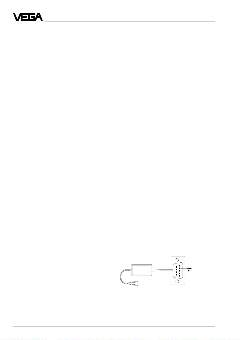
2 Electrical connection
possible. Hence HART®--capable VEGAinstruments can be adjusted with the PC and
2.1 Connection plan
the software VVO.
1
9
2
The two-wire line of VEGACONNECT 2 can be
connected in Ex-area to an Ex-approved
sensor.
VEGACONNECT 2 and PC must not be
located in Ex-area
(see connection example 3).
VBUS
2 mm-plug
VEGACONNECT2
to sensor
8
7
6
RS 232
D-Sub-socket
9-pole
RxD
3
4
5
TxD
GND
to PC
Classification intrinsic safety:
EEx ia II C / II B
EEx ib II C / II B
2 VEGACONNECT
Page 3

Operating instruction
2.2 Connection examples
Example 1
Two VBUS-sensors VEGASON 51 V in
conjunction with VEGAMET 515 V
VBUS
VEGACONNECT 2
VVO
Example 2
Sensor VEGAPULS 51 K with analogue
output signal in conjunction with a DCS
4 … 20 mA with
superimposed HART®-protocol
2
SPS
2
HART®--Hand-
HART Communicator
terminal
VEGACONNECT 2
Example 3
VBUS-sensor VEGASON 83 FV StEx in Exarea in conjunction with VEGATRENN 548Ex,
VEGAMET 515 V
Ex-area
Not Ex-area
VEGACONNECT 2
VBUS
VEGATRENN 548 Ex
VEGAMET 515 V
VVO
Example 4
VEGAPULS 81 F with analogue output signal
in conjunction with an indicating instrument
Voltage
supply
4 … 20 mA with
superimposed VBUS
Indicating
instrument
VEGACONNECT 2
VVO
VEGACONNECT 3
VVO
Page 4

Note to example 4
If the inner resistance of the connected
processing is considerably smaller than
100 W (e.g. indicating instrument), the VBUSsignal superimposed to the 0/4 … 20 mAoutput will be damped. With a low frequency
indicating instrument a load resistor of
R = 100 W must be looped into the
0/4 … 20 mA-line and the VEGACONNECT 2
must be connected to this resistor. On
analogue inputs of DCS-systems, this
resistor is normally ³ 100 W, so that no
damping occurs.
to
sensor
+
-
to PC
VEGACONNECT 2
VEGA Grieshaber KG
Am Hohenstein 113
D-77761 Schiltach
Phone (0 78 36) 50 - 0
Fax (0 78 36) 50 - 201
e-mail vega@vega-g.de
R = 100 W
Safety information
The described module must only be installed
and operated as described in this operating
instruction. Please note that other action can
cause damage for which VEGA does not take
responsibility.
ISO 9001
Technical data subject to alterations 2.22 401 / April ’98
 Loading...