

Page 1
VEGACONNECT
Operating Instructions
Connection cable
(interface
converter)
VEGACONNECT
Conversion of VBUS /
DISBUS-signals to
RS 232-signals
Enables the connection of
a PC/LAPTOP
- VEGASON-sensors
(ECHOFOX®)
- VEGAPULS-sensors
(ECHOFOX®)
- Signal conditioning
instruments VEGAMET
series 500
Parameter adjustment of
sensors and signal
conditioning instruments
via the operating software
VEGA VISUAL
OPERATING
VEGA Grieshaber KG
Am Hohenstein 113
D-77761 Schiltach
Phone 0 78 36 / 50 - 0
Fax 0 78 36 / 50 201
Page 2
Technical Information
1 Product description
VEGACONNECT connection cable is used for conversion
of VEGA-specific VBUS/DISBUS-signals to standard
RS 232-signals.
Via a 9-pole SUB-D plug VEGACONNECT is connected to
the standard interface of an available PC/LAPTOP and via
a 2 mm-plug to the CONNECT-sockets of the VEGAinstrument.
It is possible to connect the following instruments:
- ECHOFOX®-sensors
VEGASON 83 … 87 FK/GK as well as 83 … 87 FV/GV
- ECHOFOX®-sensors
VEGAPULS 64 DK/FK/UK as well as 64 DV/FV/UV
- Ex-Zone 10 (StEx)-version of these sensors
- Signal conditioning instrument VEGAMET serie 500
Further connection possibilities for VEGACONNECT are:
- The connection line between VBUS-sensor and signal
conditioning instrument
- the 0/4 … 20 mA-output of K (compact)-version of the
sensors.
VEGACONNECT is located in a stable plastic housing and
is supplied completely with connection lines and plug
connections.
2 Connection versions
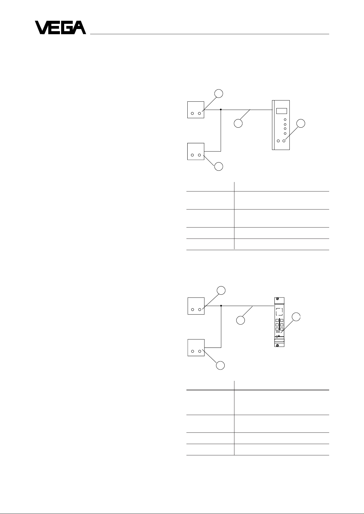
2.1 Sensor in conjunction with VEGAMET
509 V, 512 V or VEGALOG 570 with VBUScard
CONNECT-sockets on
3
the sensor
CONNECT
Sensor 1
CONNECT
Sensor 2
4
Connection points Parameter adjustment
1 Sensor 1
2 Sensor 1
3 Sensor 1
2
connection line
CONNECT-sockets on
the sensor
Sensor 2
Sensor 2
1
COM-sockets in
the front plate
COM
e.g. VEGAMET 512 V
The power supply is realized via the RS 232-interface of
PC / LAPTOP.
The operating software VEGA VISUAL OPERATING is
required to operate VEGACONNECT. It is installed on PC/
LAPTOP under WINDOWS and enables a comfortable,
menu guided parameter adjustment of ECHOFOX®sensors and signal conditioning instruments of the new
generation.
4 Sensor 2
2.2 Sensor in conjunction with VEGAMET
515 V
3
CONNECT-sockets on
CONNECT
Sensor 1
CONNECT
Sensor 2
Connection points Parameter adjustment
1 VEGAMET
2 Sensor 1
the sensor
2
connection line
CONNECT-sockets
4
on the sensor
Sensor 1
Sensor 2
Sensor 2
1
CONNECTsockets in the
front plate
e.g. VEGAMET 515 V
3 Sensor 1
4 Sensor 2
2
VEGACONNECT
Page 3

Technical Information
2.3 Sensor in conjunction with VEGALOG 571
EV-card CPU-card
connection line
16
CONNECT CONNECT CONNECT CONNECT CONNECT
sensors
1
CONNECT-sockets on
the sensor
15
Connection points Parameter adjustment
1 … 15 respective sensor
16 Sensor 1 … 15
2.4 Compact and dust Ex-sensors
CONNECT
Sensor
1
CONNECT-sockets on
the sensor
Connection points Parameter adjustment
1 Sensor
Power supply
2
connection line to
indicator
2.5 Ex-sensors with VEGAMET 509 V, 512 V,
514 V or VEGAMET 515 V
Ex-area
Sensor
Connection points Parameter adjustment
1 VEGAMET
2 Sensor
not-Ex-area
146
connection
line
Sensor
2
e.g. VEGAMET 514 V
1
CONNECTsockets in the
front plate
3 Electrical connection
1
9
VEGACONNECT
VBUS
2 mm-plug
2
8
3
4
7
6
5
RS 232
D-Sub-plug
9-pole
RxD
TxD
GND
2 Sensor
Note
A digital signal (VBUS) is additionally modulated to the
0/4 … 20 mA-output. Acc. to the connected output (e.g.
indicator) this signal is damped by the internal resistor of
the output, if it is smaller than 100 Ω. For analog inputs of
PLC-systems this resistor is generally ≥ 100 Ω, so that no
damping is caused. In case of a low impedance indicator a
load resistor of R = 100 Ω must be connected in the
0/4 … 20 mA-line and VEGACONNECT must be
connected to this resistor.
R = 100 Ω
to sensor
+
-
VEGACONNECT
4 Technical data
Power supply from PC/LAPTOP via
RS 232
Power consumption max. 8 mA
Voltage max. 15 V
Transmission rate 9.600 baud
Data format 8 bit (ASCII-Code)
Parity even
Start / Stop 1 bit each
Galvanic separation between VBUS and RS 232
Line length RS 232 approx. 30 cm
VBUS approx. 150 cm
Permissible
ambient temperature -20°C … +60°C
Storage and
transport temperature -20°C … +70°C
Housing material shock-resistant Polystyrol
upper part light grey
lower part agate
Housing dimensions W x H x D
= approx. 100 x 52 x 30 mm
Weight
- with connection line approx. 200 g
VEGACONNECT
3
Page 4

VEGA Grieshaber KG
Am Hohenstein 113
D-77761 Schiltach
Phone 0 78 36 / 50 - 0
Fax 0 78 36 / 50 201
Technical data subject to alterations 2.19 563 / Juni '95
 Loading...