

Page 1
Operating Instruction
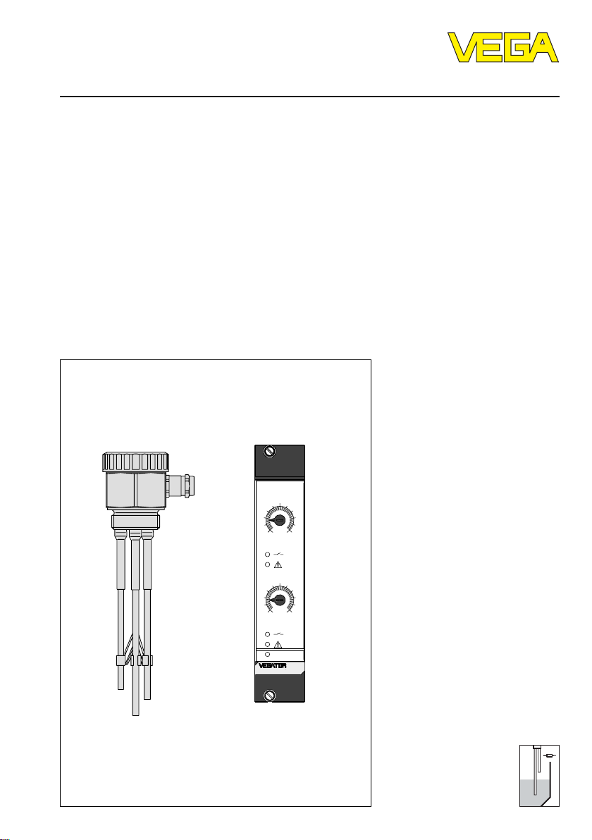
Conductive electrodes
Level and Pressure
5
100
1
5
10
0
2
on
532 Ex
Page 2

Safety information
Safety information
The described module must only be installed
and operated as described in this operating
instruction. Please note that other action can
cause damage for which VEGA does not take
responsibility.
2 Conductive measuring system
Page 3

Contents
Contents
Safety information ........................................................................ 2
1 Product description
1.1 Function and configuration .................................................. 4
1.2 Types and version ............................................................... 4
1.3 Technical data....................................................................... 5
1.4 Dimensions ......................................................................... 14
1.5 Approvals ........................................................................... 18
2 Mounting instructions
2.1 Conductive electrodes ...................................................... 19
2.2 VEGATOR 256C ................................................................. 20
2.3 VEGATOR 532 Ex ............................................................... 20
2.4 VEGATOR 631 Ex ............................................................... 22
3 Electrical connection
3.1 VEGATOR 256C ................................................................. 23
3.2 VEGATOR 532 Ex ............................................................... 23
3.3 VEGATOR 631 Ex ............................................................... 25
4 Set-up
4.1 VEGATOR 256C ................................................................. 27
4.2 VEGATOR 532 Ex ............................................................... 28
4.3 VEGATOR 631 Ex ............................................................... 32
5 Diagnosis
5.1 Fault signal on VEGATOR 532 Ex ..................................... 36
5.2 Fault signal on VEGATOR 631 Ex ..................................... 37
Conductive measuring system 3
Page 4

1 Product description
Product description
1.1 Function and configuration
The conductive measuring principle is used
for level detection of conductive liquids.
Function
When the probe (s) is covered by the
medium, conductive electrodes detect the
product resistance.
A low alternating current flows which is
measured by the electronics of the signal
conditioning instrument on amplitude and
phase position and converted into a
switching command.
The switching signal is determined by the
length or the mounting position of the
appropriate electrode (s).
Configuration
One or two conductive electrodes and a
signal conditioning instrument VEGATOR
256C, 532 Ex or 631 Ex are required to
implement a measuring system.
1.2 Types and version
VEGATOR 256C and electrode
Application:
- level detection, pump control (Min-Max)
Series:
- module unit
Power supply:
- 200 … 250 V AC
- 24 V, 42 V, 48 V, 100 … 130 V AC
Input:
- 1 channel for probes with 1 … 3 electrodes
Output:
- 1 relay (spdt)
VEGATOR 532 Ex and electrode
Application:
- 2 level detections, pump controls
(Min-Max)
Series:
- 19"-module card, 5 TE
Power supply:
- 20 … 53 V AC
- 20 … 72 V DC
Inputs:
- 2 channels for probes with 1 … 5
electrodes
Outputs:
- 2 relays (1 spdt each)
- 2 transistors
Classification:
- [EEx ia] IIC
Approvals:
- CENELEC
- WHG
Fault monitoring:
- detection of line break
VEGATOR 631 Ex and electrode
Application:
- level detection, pump control (Min-Max)
Series:
- module unit
Power supply:
- 20 … 250 V AC
- 20 … 72 V DC
Input:
- 1 channel for probes with 1 … 3 electrodes
Output:
- 1 relay (1 spdt)
- 1 transistor
Classification:
- [EEx ia] IIC
Approvals:
- CENELEC
- WHG
Fault monitoring:
- detection of line break
4 Conductive measuring system
Page 5
Product description
1.3 Technical data
Conductive electrodes
Conductive electrode type EL 1 and EL 2
Material
- connection housing 1.4571
- thread 1.4571
- welded socket (only with type EL 2) 1.4571
- rod electrode 1.4571 or Hastelloy C4
- isolation of the rod electrode PTFE
Size of the thread G
Length of the rod electrode
- type EL 1 40 … 4000 mm
- type EL 2 60 … 2000 mm
Protection IP 67
Temperature range -50°C … +130°C
Max. permissible vessel pressure 63 bar
Electrical connection Pg 11
Basic weight
- type EL 1 approx. 0,4 kg
- type EL 2 approx. 0,7 kg
Additional weight of the rod electrode approx. 0,04 kg per 100 mm
Conductive rod electrode type EL 1 Ex and EL 2 Ex
Temperature range -20°C … +100°C
Classification EEx ia IIC T6
Max. permissible ambient temperature
- temperature class T6 85°C
- temperature class T5 100°C
all other technical data like EL 1 and EL 2
1
/2 A
Conductive multiple rod electrode type EL 3 (2 … 5 rod electrodes)
Material
- connection housing 1.4571
- thread 1.4571
- rod electrodes 1.4571, Hastelloy C4 or Titanium
- isolation of the rod electrodes PTFE
- distance holder PP
Size of the thread G 1
1
/2 A
Length of the rod electrodes 100 … 4000 mm
Number of rod electrodes 2 … 5
Protection IP 67
Temperature range -50°C … +130°C
Max. permissible vessel pressure 63 bar
Electrical connection Pg 16
Basic weight approx. 0,9 kg
Additional weight of the rod electrodes approx. 0,04 kg per 100 mm
Conductive measuring system 5
Page 6
Conductive multiple rod electrode type EL 3 Ex (2 … 5 rod electrodes)
Temperature range -20°C … +100°C
Classification EEx ia IIC T6
Max. permissible ambient temperature
- temperature class T6 85°C
- temperature class T5 100°C
all other technical data like type EL 3
Conductive multiple rod electrode type EL 4 (2 … 5 rod electrodes)
Material
- connection housing PP
- thread PP
- rod electrodes 1.4571, Hastelloy C4 or Titanium
- isolation of the rod electrodes PP
- distance holder PP
Size of the thread G 1
1
/2 A
Length of the rod electrodes 100 … 4000 mm
Number of rod electrodes 2 … 5
Protection IP 67
Temperature range -20°C … +100°C
Max. permissible vessel pressure 6 bar
Electrical connection Pg 16
Basic weight approx. 0,4 kg
Additional weight of the rod electrodes approx. 0,04 kg per 100 mm
Conductive multiple cable electrode type EL 5 (2 … 5 cable electrodes)
Material
- connection housing 1.4571
- thread 1.4571
- cable electrodes 1.4571
- isolation of the cable electrodes PTFE / FEP
- gravity weight 1.4571
Size of the thread G 1
1
/2 A
Length of the cable electrodes 300 … 20000 mm
Number of cable electrodes 2 … 5
Protection IP 67
Temperature range -50°C … +100°C
Max. permissible vessel pressure 63 bar
Electrical connection Pg 16
Basic weight approx. 1 kg
Additional weight of the cable electrodes approx. 0,01 kg per 100 mm
Product description
Conductive multiple cable electrode EL 5 Ex (2 … 5 cable electrodes)
Temperature range -20°C … +100°C
Classification EEx ia IIC T6
Max. permissible ambient temperature
- temperature class T6 85°C
- temperature class T5 100°C
all other technical data like type EL 5
6 Conductive measuring system
Page 7

Product description
Conductive multiple cable electrode type EL 6 (2 … 5 cable electrodes)
Material
- connection housing PP
- thread PP
- cable electrodes 1.4571
- isolation of the cable electrodes PP / FEP
- gravity weight 1.4571
Size of the thread G 1
1
/2 A
Length of the cable electrodes 300 … 20000 mm
Number of cable electrodes 2 … 5
Protection IP 67
Temperature range -20°C … +120°C
Max. permissible vessel pressure 6 bar
Electrical connection Pg 16
Basic weight approx. 0,5 kg
Additional weight of the cable electrodes approx. 0,01 kg per 100 mm
Conductive rod electrode type EL 8
Material
- connection housing plastic
- thread 1.4305
- rod electrode 1.4571
- isolation of the rod electrode PE
Size of the thread G
1
/2 A
Length of the rod electrode 30 … 1000 mm
Protection IP 50
Temperature range -10°C … +60°C
Max. permissible vessel pressure 6 bar
Basic weight approx. 0,1 kg
Additional weight of the rod electrode approx. 0,04 kg per 100 mm
Conductive cable electrode type EL 9
Material
- connection housing 1.4571
- thread 1.4571
- cable electrode 1.4571
- isolation of the cable electrode FEP
- gravity weight 1.4571
Size of the thread G
1
/2 A
Length of the cable electrode 500 … 25000 mm
Protection IP 67
Temperature range -50°C … +100°C
Max. permissible vessel pressure 63 bar
Electrical connection Pg 11
Basic weight approx. 0,6 kg
Additional weight of the cable electrode approx. 0,01 kg per 100 mm
Conductive measuring system 7
Page 8

Conductive cable electrode type EL 9 Ex
Temperature range -20°C … +100°C
Classification EEx ia IIC T6
Max. permissible ambient temperature
- temperature class T6 85°C
- temperature class T5 100°C
all other technical data like type EL 9
Signal conditioning instrument VEGATOR 256C
General
Series module unit
Mounting 2 holes for M3 or carrier rail mounting
acc. to DIN 46 277, Bl. 3
Dimensions W = 37 mm, H = 69 mm, D = 80 mm
Weight approx. 160 g
Power supply
Operating voltage
- standard 200 … 250 V AC, 50/60 Hz
- option 24 V, 42 V, 48 V, 100 … 130 V AC
+10 %, –15 %, 50/60 Hz
Power consumption 1 VA
Product description
Measuring data input
Number 1 (1 x level detection or
Response resistor 1 … 200 kOhm adjustable
Meas. circuit approx. 12 V eff, approx. 1 mA
Switching hysteresis approx. 20 %
Relay output
Number 1 (1 x level detection)
Mode overfill protection (A)
Contact spdt
Contact material
Turn-on voltage min. 10 mV
Switching current min. 10 µA
Breaking capacity max. 750 VA or 54 W
Integration time
Fixed value approx. 500 ms
8 Conductive measuring system
1 x pump control -Min-Max.)
max. 250 V AC or 250 V DC
max. 5 A AC or 1 A DC
Page 9

Product description
Ambient conditions
Permissible operating temperature -20°C … +50°C
Storage and transport temperature -40°C … +70°C
Electrical protective measures
Protection IP 20
Protection class II
Electrical connection
Screw terminal max. for 1,5 mm
2
CE-conformity
VEGATOR 256C signal conditioning instrument meets the protective regulations of EMVG
(89/336/EWG) and NSR (72/23/EWG). The conformity has been judged acc. to the following
standards:
EMVG Emission EN 50 081 - 1
Susceptibility EN 50 082 - 2
NSR EN 61 010 - 1
Signal conditioning instrument VEGATOR 532 Ex
General
Series 19"-module card, multipoint connector acc. to
Dimensions B = 25,4 mm (5 TE), H = 128,4 mm, D = 162 mm
Weight approx. 170 g
DIN 41 612 incl. transparent cover
Power supply
Operating voltage 20 … 53 V AC, 50/60 Hz
20 … 72 V DC
Power consumption max. 2 W, 3 VA
Fuse
- supply range T 1 A, 250 V
- switching power min. 35 A at 250 V AC or 125 V DC
Measuring data input (channel)
Number 2 (2 x level detection or
2 x pump control -Min-Max)
Response resistor 1 … 200 kOhm adjustable
Parallel resistor
- for fault monitoring 220 kOhm
Meas. circuit max. 5 V eff, max. 1 mA
Permissible line capacitance 1 x 100 nF or
2 x 70 nF with Min-Max.-control
Switching hysteresis approx. 15 %
Conductive measuring system 9
Page 10

Product description
Measuring data input, Ex-technical data
Signal circuits in classification intrinsic safety EEx ia IIC
Max. values
-U
O
-I
K
- P 20 mW
10,6 V
8 mA
Characteristics linear
Inner effective inductance negligible
Inner effective capacitance negligible
Max. permissible outer inductance 5 mH
Max. permissible outer capacitance 570 nF
The intrinsically safe circuits are reliably galvanically separated from the not-intrinsically
safe circuits up to a peak value of the nominal voltage of 375 V.
The intrinsically safe circuits of channel 1 and channel 2 are reliably galvanically isolated.
Relay outputs
Number 2
Mode overfill protection (A) and dry run protection (B)
changeover for each output (channel) separately
Contact 1 spdt per output
Contact material AgCdO and Au plated
Turn-on voltage min. 10 mV
max. 250 V AC or 250 V DC
Switching current min. 10 µA
max. 3 A AC or 1 A DC
Breaking capacity max. 750 VA or 54 W
Transistor outputs
Number 2 (synchronously switching with relay outputs)
Galvanic isolation floating
Turn-on voltage U
Switching current IB = max. 60 mA
Voltage loss on the transistor U
Blocking current I
= max. 36 V DC
B
= approx. 1,5 V at IB = 60 mA
CE
< 10 µA
O
Integration time
Fixed value approx. 500 ms
Ambient conditions
Permissible ambient temperature -20°C … +60°C
Storage and transport temperature -40°C … +70°C
10 Conductive measuring system
Page 11

Product description
Electrical protective measures
Protection
- not mounted IP 00
- mounted into
carrier BGT 596 Ex front side completely equipped IP 30
upper and lower side IP 20
wiring side IP 00
- mounted into
housing type 505 Ex IP 30
Protection class II
Overvoltage category II
Electrical connection
Mounted into
- carrier BGT 596 Ex 33-pole multipoint connector, series F (d, b, z)
- housing type 505 Ex screw terminal, max. for 1,5 mm
with coding holes
2
CE-conformity
VEGATOR 532 Ex signal conditioning instrument meets the protective regulations of EMVG
(89/336/EWG) and NSR (72/23/EWG). The conformity has been judged acc. to the following
standards:
EMVG Emission EN 50 081 - 1
Susceptibility EN 50 082 - 2
NSR EN 61 010 - 1
Signal conditioning instrument VEGATOR 631 Ex
General
Series module unit with plug-in socket including
Dimensions W = 36 mm, H = 118,5 mm, D = 134 mm
Weight approx. 170 g
Mounting carrier rail mounting acc. to DIN 46 277, Bl 3
Power supply
Operating voltage 20 … 250 V AC, 50/60 Hz
Power consumption max. 1,5 W, approx. 1 … 9 VA
Fuse
- supply range T 315 mA, 250 V
- switching power min. 35 A at 250 V AC or 125 V DC
Conductive measuring system 11
transparent cover, cover of the probe
terminals,
coded pin, 2 bridges
20 … 72 V DC
Page 12

Product description
Measuring data input (channel)
Number 1 (1 x level detection or
1 x pump control -Min-Max)
Response resistance 1 … 200 kOhm adjustable
Parallel resistance
- for fault monitoring 220 kOhm
Meas. circuit max. 5 V eff, max. 1 mA
Permissible line capacitance 1 x 100 nF or
2 x 70 nF at Min-Max.-control
Switching hysteresis approx. 15 %
Measuring data input, Ex-technical data
Signal circuit in classification intrinsic safety EEx ia IIC
Max. values
-U
O
-I
K
- P 20 mW
10,6 V
8 mA
Characteristics linear
Inner effective inductance negligible
Inner effective capacitance negligible
Max. permissible outer inductance 5 mH
Max. permissible outer capacitance 570 nF
The intrinsically safe circuits are reliably galvanically isolated from the not-intrinsically safe
circuits up to a peak value of the nominal voltage of 375 V.
Relay outputs
Number 1
Mode overfill protection (A) and dry run protection (B)
changeable
Contact 1 spdt per output
Contact material AgCdO and Au plated
Turn-on voltage min. 10 mV
max. 250 V AC or 250 V DC
Switching current min. 10 µA
max. 3 A AC or 1 A DC
Breaking capacity max. 750 VA or 54 W
Transistor outputs
Number 1 (synchronuously switching with relay outputs)
Galvanic isolation floating
Turn-on voltage U
Switching current I
Voltage loss on transistor U
Blocking current IO < 10 µA
= max. 36 V DC
B
= max. 60 mA
B
= approx. 1,5 V at IB = 60 mA
CE
Integration time
Adjustable 0,2 … 20 s
12 Conductive measuring system
Page 13

Product description
Ambient conditions
Permissible operating temperature -20°C … +60°C
Storage and transport temperature -40°C … +70°C
Electrical protective measures
Protection IP 20
Protection class II
Overvoltage category II
Electrical connection
Screw terminals max. for 1,5 mm
2
CE-conformity
VEGATOR 631 Ex signal conditioning instrument meets the protective regulations of EMVG
(89/336/EWG) and NSR (72/23/EWG). The conformity has been judged acc. to the following
standards:
EMVG Emission EN 50 081 - 1
Susceptibility EN 50 082 - 2
NSR EN 61 010 - 1
Conductive measuring system 13
Page 14

1.4 Dimensions
Conductive electrodes
Type EL 1 (Ex) Type EL 2 (Ex)
~43
ø46
~43
ø46
Product description
56
18
L (max. 4000 mm)
SW 41
G 1/2 A
ø10
ø8
Pg 11
~114
60
Pg 11
SW 41
ø34
ø10
ø11
Type EL 3 (Ex) Type EL 4
SW 60
58
~58
ø66
Pg 16
20
1
/2 A
G 1
SW 60
54
22
78
ø66
~58
G 1
1
Pg 16
/2 A
L1
L3
L2
L1
L3
L2
ø6
L1 = Longest rod electrode, L2 = Shortest rod electrode
L1 = Longest rod electrode, L2 = Shortest rod electrode
ø4
14 Conductive measuring system
Page 15

Product description
Type EL 5 (Ex) Type EL 6
SW 60
~58
ø66
SW 60
~58
ø66
58
Pg 16
20
1
/2 A
65
ø2,5
G 1
PTFE
1.4571
FEP
L3
L2
L1
80
L1 = Longest cable electrode, L2 = Shortest cable electrode
54
Pg 16
22
G 1
1
/2 A
78
PP
ø2,5
1.4571
FEP
L1 = Longest cable electrode, L2 = Shortest cable electrode
L3
L2
L1
Conductive measuring system 15
Page 16

Type EL 8 Type EL 9 (Ex)
ø24
9,3
30
12
27
L (max. 1000 mm)
SW 24
56
ø6,8
ø4
ø46
18
80
40
Product description
~43
Pg 11
SW 41
G 1/2 A
ø10
VEGATOR 256C
66
L
ø4,6
200
ø15
4
min.
1
max.
2
3
10
0
68
4
5
200...250VAC 3VA
6
R
L1
N
ax 250V,5A,750VA
7
power supply
Relais: m
8
37
22
60
7,5
16 Conductive measuring system
Page 17

Product description
VEGATOR 532 Ex
5,5
9
15
3
VEGATOR 631 Ex
162
Carrier rail 35 x 7,5 or
35 x 15 acc. to EN 50 022
Multiple plug
5 TE
100
on
25,4
128,4
Transparent cover
12 34
5
118,5
010
on
54,5
134
631Ex
56 78
9 1011121314
36
Conductive measuring system 17
Page 18

Product description
1.5 Approvals
If measuring systems are installed according to the following approvals, the appropriate legal
documents and their regulations must be noted. The documents are supplied with the
appropriate measuring system.
WHG-approval
Signal conditioning instrument VEGATOR 532 Ex, VEGATOR 631 Ex, (VEGATOR 535 Ex)
together with conductive electrodes type EL 1 Ex, EL 2 Ex, EL 3 Ex, EL 5 Ex, EL 9 Ex as part
of an overfill protection acc. to WHG, no. Z-65.13-7.
Ex-approval
For measuring systems in hazardous areas, certificate acc. to CENELEC.
Conductive electrodes
- Type EL 1 Ex
- Type EL 3 Ex (2 … 5 rod electrodes)
- Type EL 5 Ex (2 … 5 cable electrodes)
- Type EL 9 Ex
defined in conformity certificate PTB-no. Ex-93.C.4048 X
Signal conditioning instrument VEGATOR 532 Ex
Conformity certificate PTB-no. Ex-96.D.2055 X
Signal conditioning instrument VEGATOR 631 Ex
Conformity certificate PTB-no. Ex-96.D.2064
CE-approval
- VEGATOR 256C
- VEGATOR 532 Ex
- VEGATOR 631 Ex
see the appropriate technical data
18 Conductive measuring system
Page 19

Mounting instructions
2 Mounting instructions
2.1 Conductive electrodes
General
When mounting the electrodes it should be
noted that the rod or cable electrodes do not
touch the vessel wall.
Lateral load
Note that the electrode is not subjected to
strong lateral forces.
Mount the electrode on a position in the
vessel where no interferences such as e.g.
by stirrers, vessel openings etc. occur. This
is mainly valid for very long rod and cable
electrodes.
If a modification of the installation place
should not be possible for you, it would be
necessary that the rod or cable electrodes
must be stabilized by an isolated holder.
Pressure
In case of gauge or low pressure in the
vessel, the mounting boss must be sealed on
the thread. Use the attached seal ring. Check
if the seal ring is resistant against the
medium.
Note for electrodes with earth rod (e.g. EL 1,
EL 2, EL 8) that the thread of the electrode is
electrically conductive connected with the
vessel to ensure a sufficient ground.
Use conductive seals such as e.g. copper,
lead etc. Isolating measures such as e.g.
covering the thread with Teflon tape or a
paper seal can interrupt the necessary
electrical connection.
In this case connect the earth connection
terminal on the electrode housing via an
external earth cable to the vessel.
Ex-measuring systems
Important instruction for multiple rod or multiple cable electrodes type … Ex, VEGATOR
532 Ex and VEGATOR 631 Ex. To implement
a line monitoring, a resistor of 220 kOhm is
mounted between terminal 1 and terminal 2 in
the connection housing. Please note that in
case you want to adap the rod or cable
electrode by yourself, i.e. shortening so that
L1 or terminal 1 corresponds to the longest
and L2 or terminal 2 to the shortest rod or
cable electrode (see also paragraph "Fault
signal").
Probe with 3 rod or cable
2
1
3
Conductive measuring system 19
electrodes
Page 20

Mounting instructions
4
60
7,5
22
Probe with 4 rod or cable
3
2
1
4
electrodes
Probe with 5 rod or cable
3
2
4
5
1
electrodes
2.2 VEGA TOR 256C
The signal conditioning instrument VEGATOR
256C can be either mounted directly to the
wall via two screws or plugged to a carrier
rail 35 x 7,5 acc. to DIN EN 50 022.
Carrier rail mounting
Place VEGATOR 256C from the bottom to the
carrier rail and push the instrument to the rail
until snap-in.
Wall mounting
Fasten the instrument directly to the wall by
means of two screws (ø max. 3 mm).
2.3 VEGA T OR 532 Ex
VEGATOR 532 Ex can be either mounted in a
single housing type 505 Ex or into a carrier
BGT 596 or BGT 596 Ex by means of a
module.
- Module consisting of:
Multipoint connector DIN 41 612, series F,
33-pole (d, b, z) with coded pin and
mounting material for mounting in carrier
BGT 596
- Ex-module consisting of:
Multipoint connector DIN 41 612, series F,
33-pole (d, b, z) with coded pins, Exseparating chamber and mounting material
for mounting in carrier BGT 596 Ex
- Single housing
Plastic housing type 505 Ex for single
mounting of signal conditioning instrument
with instrument width 5 TE (25,4 mm)
Mounting carrier
Mount the appropriate module (standard or
Ex-version) on your carrier BGT 596 or BGT
596 Ex. Wire the connection of the multipoint
connector acc. to section "3 Electrical
connection".
The multipoint connector is available as
follows:
- Wire-Wrap standard connection
1,0 x 1,0 mm
- Plug connection 2,8 x 0,8 mm
- Termi-Point standard connection
1,6 x 0,8 mm
- Soldering connection
- Screw terminals 2 x 0,5 mm
2
For further information concerning mounting
see the operating instruction of the carrier.
When mounting VEGATOR 532 with Exapproval into a carrier, you have to use a
VEGA-Ex-module. Keep a distance of at least
10 mm (2 TE) to instruments of other
manufacturers. When you want to mount
VEGATOR completely to the left in the carrier,
you have to mount a blind cover of at least
20 mm (4 TE) in front of the module of the
instrument.
20 Conductive measuring system
Page 21

o 31 o
o 29 o
o 27 o
o 25 o
o 23 o
o 21 o
o 19 o
o 15 o
o 11 o
o 7 o
o 3 o
o 1 o
o 5 o
o 9 o
o 13 o
o 17 o
a c
Mounting instructions
2
on
VEGATOR
Instrument type coding Function coding
c7 VEGATOR
VEGATOR 532 Ex a20
Blindcover
c23 Ex-module
card
Ex-separating chamber
To ensure sufficient "Air and creeping
distances" an Ex-separating chamber must
be mounted for the measuring data inputs in
case of Ex-applications. First of all loop the
lines through the Ex-separating chamber and
connect the lines. When using a multipoint
connector type "Screw terminals" the lower
wall on the Ex-separating chamber must be
broken away acc. to the notches. Fasten the
Ex-separating chamber with the lower screw.
Transparent cover
To protect the instrument against
unauthorized adjustment, the front plate of
VEGATOR 532 Ex can be provided with a
lockable transparent cover.
Note the operating instruction of the carrier.
Mounting single housing type 505 Ex
Coding
To exclude interchanging of the module card
VEGATOR 532 Ex, the multipoint connector of
the housing or the carrier rail is provided with
pins and the multiple plug of the module card
with holes (mechanical coding).
A function coding with fixed coded pin
ensures that not-Ex and Ex-module cards
The socket can be either screwed directly to
the mounting plate or plugged on a carrier
rail (TS 35 x 7,5 acc. to EN 50 022 or TS 32
acc. to EN 50 035).
Connect the terminals of the basic plate acc.
to paragraph "3 Electrical connection". Further information on mounting is stated in the
operating instruction of the housing.
are not interchanged.
An instrument coding with the coded pins
attached to the housing or module ensures
that the signal conditioning instruments are
not interchanged.
Insert the two coded pins into the determined
holes of the multipoint connector.
Conductive measuring system 21
Protection with Ex-applications
For Ex-applications a protection of IP 20 must
be maintained. Therefore cover the gaps or
not coordinated modules from the front by
appropriate blind covers.
Page 22

Mounting instructions
2.4 VEGA T OR 631 Ex
Connect the signal conditioning instrument as
follows:
- Mount the plug-in socket to the carrier rail.
- Wire the socket acc. to your requirements,
see paragraph "3 Electrical connection".
- Close the upper terminals with the supplied
covers.
- Insert the supplied coded pin into the
determined hole no. 3.
- Connect, if requested, the neighbouring
series 600 signal conditioning instrument
via the supplied plug (L1 and N).
- Choose mode A or B on the slide switch
(laterally on top).
- Mount VEGATOR 631 Ex to the plug-in
socket (2 screws).
Cover
4321
Function coding
Ex-version
Instrument coding
VEGATOR 631
A
B
C
1
2
3
-
+
Mounting of the covers
12 43
Transparent cover
To protect the instrument against
unauthorized adjustment, the front plate of
VEGATOR 631 Ex can be provided with a
lockable transparent cover, see following
figure.
7
8
9
Plug
N
L
1
56 78
14131211109
22 Conductive measuring system
Page 23

Electrical connection
3 Electrical connection
3.1 VEGATOR 256C
Level detection
Mass
12
Relay output
Power supply
Electrode
e.g. type EL 1
Pump control
(Min-Max-control)
Mass
Max
Min
2
3
1
Relay output
Power supply
Connect several VEGATOR 256 C absolutely
identical, i.e. the first supply line to all
terminals no. 7 and the second supply line to
all terminals no. 8. An interchanging of no. 7
and no. 8 or the connection of different
phases is not permitted.
3.2 VEGATOR 532 Ex
min.
1
max.
2
3
10
0
4
5
200...250VAC 3VA
6
R
L1
7
power supply
Relais: max 250V,5A,750VA
8
N
min.
1
max.
2
3
10
0
4
5
200...250VAC 3VA
6
R
L1
7
power supply
Relais: max 250V,5A,750VA
8
N
To avoid interferences by capacitive
couplings, use from a line length of 50 m an
own cable for each signal conditioning
instrument VEGATOR 532 Ex or for each
channel.
When you want to use a commen cable, note
that the lines of the max. and min. signal are
screened. Connect the screens to mass.
Double level detection
d b z
+-
2
Power
supply
Transistor output 1
Meas. data input 1
(channel 1)
2
1
L (+)
N (-)
6
10
12
16
18
20
22
24
Mass
28
Max
30
Min
3
32
+
+
-
-
Relay output 1
Relay output 2
Transistor output 2
Meas. data input 2
(channel 2)
2
3
1
Electrode
e.g. type EL 3
Note
Multiple rod electrodes which are connected
to several signal conditioning instruments or
a multiple channel instrument, require an
earth rod to avoid influencing among the
signal conditioning instruments.
Conductive measuring system 23
1
2
3
Electrode
e.g. type EL 3
Page 24

Electrical connection
Pump control
(Min-Max-control)
3
Electrode
e.g. type EL 3
L (+)
N (-)
Mass
Max
Min
Power
supply
Transistor output 1
Meas. data input 1
(channel 1)
2
3
1
2
1
d b z
+-
2
6
10
12
16
18
+
20
-
22
24
28
30
32
Relay output 1
Relay output 2
+
-
Transistor output 2
Meas. data input 2
(channel 2)
Double pump control
For a double pump control e.g. with EL 5 you
require a VEGATOR 532 Ex.
d b z
+-
Power
supply
Transistor output 1
Mass
Max
Min
3
4
2
1
5
L (+)
N (-)
2
6
10
12
16
18
+
20
-
22
24
28
30
32
Relay output 1
Relay output 2
+
-
Transistor output 2
Max
Min
Note
Multiple rod electrodes which are connected
to several signal conditioning instruments or
a multiple channel instrument require an earth
rod to avoid influencing among the signal
conditioning instruments.
24 Conductive measuring system
2
Electrode
5
4
e.g. type EL 5
3
1
Page 25

Electrical connection
VEGATOR 532 Ex with housing
type 505
The terminal designation for the power
supply and the relay or transistor output
corresponds to that of the multipoint
connector. Just the connection of the
electrodes must be made as follows.
Double Pump control
level detection (Min-Max-control)
1 2 3 1 2 3
2
3
1
1 2 3 1 2 3
2
3
1
3.3 VEGA T OR 631 Ex
To avoid interferences due to capacitive
coupling, use from a line length of 50 m an
own cable for each signal conditioning
instrument VEGATOR 631 Ex.
When you want to use a commen cable, note
that the lines of the max. and min. signal are
screened. Connect the screens to mass.
Level detection
Mass
Pump control
(Min-Max-control)
Mass
Max
Min
2
3
1
2
3
1
132 4
5 6
9 10
7 8
131412
Relay output
Power supply
Electrode
e.g. type EL 3
Transistor output
Note
Multiple rod electrodes which are connected
to several signal conditioning instruments or
a multiple channel cable require an earth rod
to avoid influencing among the signal
conditioning instruments.
Pump control (Min-Max) with overfill
protection
Max-ÜFS
2
3
1
Min
4
Max
Mass
12
Electrode
e.g. type EL 1
56
910
21
43
141312
Relay output
Power supply
2
3
4
1
1 32 4
5 6
9 10 131412
L
N
(+)
(–)
1
32 4
5 6
7 8
9 10 131412
L
N
(+)
(–)
7 8
Transistor output
Conductive measuring system 25
Page 26

Coordination of the transistor outputs
VEGATOR 532 Ex and 631 Ex
R
S
+
U
CE
-
R
S
+
U
CE
-
+
+
-
Electrical connection
VEGATOR 532 Ex
(VEGATOR 631 Ex)
DCS
The resistor RS is used as shortcircuit
protection.
R
S
P
47 Ohm 0,25 W
150 Ohm 0,75 W
330 Ohm 1,5 W
560 Ohm 2,2 W
26 Conductive measuring system
Page 27

Set-up
4 Set-up
4.1 VEGATOR 256C
Indicating and adjustment elements
Potentiometer
The switch point or the adaption to the
product conductivity can be adjusted via a
potentiometer. Use a small screwdriver to
carry out the adjustments on the
potentiometer.
Yellow control lamp
lights when the relay is energized,
extinguishes when the relay is deenergized.
min.
1
max.
2
3
LED relay output
AC 3VA
10
0
4
5
6
L1
7
8
N
Switch point adjustment
Level detection
- Connect the signal conditioning instrument
- Turn the potentiometer anticlockwise up to
complete left position
- Fill the vessel until the max. electrode is
covered by approx. 1 cm
- Turn the potentiometer slowly clockwise
until the yellow LED lights
Potentiometer for switch point
adjustment
200...250V
R
power supply
Relais: max 250V,5A,750VA
Pump control (Min-Max-control)
Pre-requirements
- First of all connect only the mass and max.
electrode to the signal conditioning
instrument terminal 2 and 3
- Connect the signal conditioning instrument
to the power supply
Adjust switch point
- Turn the potentiometer anticlockwise up to
complete left position
- Fill the vessel until the max. electrode is
covered by approx. 1 cm
- Turn the potentiometer slowly clockwise
until the yellow LED lights
- Now connect the min. electrode to terminal
1 of the signal conditioning instrument
The switching sensitivity of the signal
conditioning instrument is adapted to the
product conductivity, i.e. the relay of the
output deenergizes at max. level and the
yellow LED extinguishes.
This condition remains until the level
decreases the position of the min. electrode,
i.e. the relay of the output energizes at min.
level and the yellow LED lights.
The relay of the output energizes again at
max. level etc.
The switching conductivity of the signal
conditioning instrument is adapted to the
product conductivity.
Conductive measuring system 27
Page 28

4.2 VEGA T OR 532 Ex
Set-up
B A
B A
18
1 Ex-fuse T50 mA / 250 V
2 Mains fuse T 1 A / 250 V
3 Connection plan
4 Lockable screw
5 Potentiometer for switch point
adjustment for channel 1
6 LED output 1
1
17
14
7 LED fault signal channel 1
8 Potentiometer for switch point
adjustment for channel 2
9 LED output 2
10LED fault signal channel 2
11LED supply voltage
12 Screw
13 Multiple plug
3
2
BR1
BR2
15
1316
4
5
5
6
010
7
8
9
10
11
12
1
5
010
2
on
532 Ex
14Soldering bridge for fault signal
adjustment channel 1
15Soldering bridge for fault signal
adjustment channel 2
16Selection switch mode A/B for
channel 1
17Selection switch mode A/B for
channel 2
18Transparent cover
Indicating and adjustment elements
Potentiometer
The switch point or the adaption to the
product conductivity can be adjusted via
potentiometer separately for each channel.
Use a small screwdriver to carry out the
adjustments on the potentiometer.
Control lamps
LED in the front plate indicate
operation, switching condition of the relay
outputs and fault signals.
Two yellow LED (6 and 9) for status
indication of the relay or transistor outputs
1 and 2 (LED lights = relay energizes,
transistor conductive, LED extinguished =
relay deenergizes, transistor blocked)
Two red LED (7 and 10) for failure
indication of channel 1 and 2 (LED lights =
channel interferred).
One green LED (11) for indication
operating voltage "on".
28 Conductive measuring system
Page 29

Set-up
Selection of mode A/B
A slide switch (16 and 17) per channel is
located on the circuit board of the signal
conditioning instrument. Position A
corresponds to overfill protection, position B
to dry run protection.
Failure adjustment (soldering bridges)
For monitoring of the electrodes and their
circuits, a resistor of 220 kOhm must be
mounted between connection 1 and
connection 2 in the connection housing of the
electrode, i.e. with single point control
measuring and mass electrodes are
monitored and with double point control max.
and mass electrode.
For electrodes without 220 kOhm resistor, a
soldering bridge must be closed on the
circuit board on the multipoint connector of
the signal conditioning instrument
- relating to channel 1 = bridge BR1 (14)
- relating to channel 2 = bridge BR2 (15).
Note
With closed soldering bridge the line
monitoring and appropriate fault signal are
inactive.
If a measuring system is used as part of an
overfill protection, the appropriate soldering
bridge must not be closed.
With Ex-electrodes of VEGA this resistor is
already available as a standard feature.
Selection of the mode
By means of the two selection switches (16
and 17) mode A or B can be adjusted
separately for each channel.
means with uncovered max.-electrode (level
detection) or min.-electrode (pump control)
- relay of output 1 energizes,
connection d10 - z10 is connected through
relays
- transistor output 1 is conductive
- LED relay output 1 lights
2
3
1
Mode B
preferably as dry run protection
means with covered max.-electrode
- relay of output 1 energizes,
connection d10 - z10 is connected through
relays
- transistor output 1 is conductive
- LED output 1 lights
means with uncovered max.-electrode (single point control) or min.-electrode (double
point control)
- relay of output 1 deenergizes,
connection d10 - b10 is connected through
relays
- transistor output 1 blocks
- LED output 1 extinguishes
Mode A
preferably as overflow protection
compulsorily as overfill protection
2
3
means with covered max.-electrode
1
- relay of output 1 deenergizes,
connection d10 - b10 are connected
through relays
- transistor output 1 blocks
- LED output 1 extinguishes
Conductive measuring system 29
Page 30

Set-up VEGATOR 532 Ex
Switch point adjustment
Double single point control
Min.-/Max.-signal separately
Pre-requirements
- Coordinate channel 1 to the max.-signal
- Coordinate channel 2 to the min.-signal
- Set the selection switch of channel 1 (16) to
mode A
- Set the selection switch of channel 2 (17) to
mode B
- Connect the signal conditioning instrument
to power supply
- Turn the potentiometer (5) to position 0
Switch point max.-signal
- Fill the vessel until the max. electrode is
covered by approx. 1 cm
- Turn the potentiometer (5) slowly clockwise
until the yellow LED of channel 1
extinguishes.
The max. electrode is now adapted to the
product conductivity, i.e. the relay of output 1
deenergizes at max. level and the transistor
of output 1 blocks.
Switch point min.-signal
- Turn the potentiometer (8) to position 10
- Empty the vessel until the min. electrode is
covered by approx. 1 cm
- Turn the potentiometer (8) slowly
anticlockwise until the yellow LED of
channel 2 extinguishes.
The min. electrode is now adapted to the
product conductivity, i.e. the relay of output 2
deenergizes at min. level and the transistor of
output 2 blocks.
Pump control, mode A
Overflow protection (channel 1)
Pre-requirements
- First of all connect only the mass and the
max. electrodes to the signal conditioning
instrument (connection points d28 and
d30)
- Set the selection switch of channel 1 (16) to
mode A
- Connect the signal conditioning instrument
to power supply
- Turn the potentiometer (5) to position 0
Adjust switch point
- Fill the vessel until the max. electrode is
covered by approx. 1 cm
- Turn the potentiometer (5) slowly clockwise
until the yellow LED of channel 1
extinguishes
- Now connect the min. electrode to
connection point d32 of the signal
conditioning instrument
The pump control is adapted to the product
conductivity, i.e. the relay of output 1
deenergizes at max. level and the transistor
of output 1 blocks.
This switching condition remains until the level
decreases the position of the min. electrode,
i.e. the relay of output 1 energizes at min.
level and the transistor of output 1 is
conductive.
Only at max. level, the relay of output 1
deenergizes again and the transistor of
output 1 blocks.
30 Conductive measuring system
Page 31

Set-up VEGATOR 532 Ex
Pump control, mode B
Dry run protection (channel 1)
Pre-requirements
- First of all connect only the mass and the
max. electrodes to the signal conditioning
instrument (connection points d28 and
d30)
- Set the selection switch of channel 1 (16) to
mode B
- Connect the signal conditioning instrument
to power supply
- Turn the potentiometer (5) to position 10
Adjust switch point
- Fill the vessel until the max. electrode is
covered by approx. 1 cm
- Turn the potentiometer (5) slowly
anticlockwise until the yellow LED of
channel 1 extinguishes
- Now connect the min. electrode to the
connection point d32 of the signal
conditioning instrument
The pump control is adapted to the product
conductivity, i.e. the relay of output 1
energizes at max. level and the transistor of
output 1 is conductive.
This switching condition remains until the level
decreases the position of the min. electrode,
i.e. the relay of output 1 deenergizes at min.
level and the transistor of output 1 blocks.
Note
For all switch point adjustments it must be
generally noted that between reaching of the
switch point and triggering of the switching
function an integration time of 0,5 s is
effective. The potentiometer must therefore
be turned slowly.
In all applications in conjunction with an integral resistor of 220 kOhm a line monitoring of
the mass and max. electrode must be
guaranteed.
Only at max. level the relay of output 1
energizes again and the transistor of output 1
is conductive.
These set-up examples relate to channel 1,
the same procedure is valid for channel 2.
Conductive measuring system 31
Page 32

4.3 VEGA T OR 631 Ex
12 34
!
5
010
on
631Ex
56 78
91011121314
1
2
3
4
A
B
C
1
2
3
7
8
9
N
L
1
56 78
Set-up
12
sec t
6
off
1234
B
R
VEGA TOR 631 EX
U
L
< x,xxV,
o
o
< x mH
C
< x mA
I
o
o
< xxx nF
P
< xxmW
o
Sensor
Terminal
maximum
minimum
34
12
out
max: 36V
+
56
13
CE
: -20É+60¡C
a
IP 30
nsp. I
power supply
20É250 VAC
max.250VAC
60mA
-
20É72VDC
125VA
1...8 VA
2A
L
N
+
-
12 13
14
910
15
2
5
4321
A
6
7
8
+
PTB-Nr.: Ex-96.D.2064
Sensorstromkreis EEx ia IIC
9
10
11
14131211109
12
14
1 LED fault signal
2 Potentiometer for switch point
adjustment
3 LED output
4 LED supply voltage
5 Bridge for failure adjustment
6 Terminal for electrode
7 Function coding Ex-version
8 Instrument coding VEGATOR
631 Ex
Indicating and adjustment elements
Potentiometer
The switch point or the adaption to the
product conductivity can be adjusted via a
potentiometer.
Use a small screwdriver to carry out
adjustments on the potentiometer.
9 Sockets for connection bridges
10Transistor output
11Relay output
12 Power supply
13DIL-switch block
14Type plate
15Transparent cover
Control lamps
LED in the front plate indicate
operation, switching condition of the relay
output and fault signal.
One yellow LED (3) for status indication of
the relay or transistor output (LED lights =
relay energized, transistor conductive,
LED extinguished = relay deenergized,
transistor blocks)
One red LED (1) for failure indication (LED
lights = fault signal).
One green LED (4) for indication operating
voltage "on".
32 Conductive measuring system
Page 33

Set-up
DIL-switch block
A DIL-switch block with 4 switches is located
laterally on top (covered in mounted
condition). The individual switches are
coordinated as follows:
1 A/B-mode
A - Max. detection or overfill protection
B - Min. detection or dry run protection
2 Integration time 2 s
3 Integration time 6 s
4 Integration time 12 s
With switch 1 the mode (A - overfill protection
or B - dry run protection) can be adjusted.
In the example in the figure mode A (max.
detection or overfill protection) is selected
(switch 1). The integration time is adjusted to
8 seconds (switch 2, 3 and 4).
1 A/B-mode
sec t
2 Integration time +2 s
3 Integration time +6 s
4 Integration time +12 s
62A
1234
off
B
12
With switches 2, 3 and 4 the integration time
can be appropriately adjusted. The times of
the activated timer sum up. The adjusted time
is valid for the switch on and off delay.
Switch 1234
Time 2 s 6 s 12 s
0,2 s A/B off off off
2 s A/B on off off
6 s A/B off on off
8 s A/B on on off
12 s A/B off off on
14 s A/B on off on
18 s A/B off on on
20 s A/B on on on
Failure adjustment, bridge (5)
For monitoring of the electrodes and their
circuit a resistor of 220 kOhm must be
mounted between connection 1 and
connection 2 in the connection housing of the
electrode, i.e. with single point control
measuring and mass electrode are
monitored and with double point control max.
and mass electrode.
For electrodes without 220 kOhm resistor a
bridge (5) must be provided on the signal
conditioning instrument between terminals 3
and 4.
Note
With this bridge, the line monitoring and the
fault signal are inactive.
If a measuring system is used as part of an
overfill protection, the bridge must not be
closed.
On Ex-electrodes of VEGA this resistor is
already available as factory setting.
Selection of mode
Mode A or B can be adjusted by means of
the selection switch (13).
Mode A
preferably as overflow protection
compulsorily as overfill protection
means with covered max.-electrode
- relay deenergizes, connection 12 - 13 is
connected through relay
- transistor output blocks
- LED output extinguishes
means with uncovered max.-electrode (level
detection) or min.-electrode (pump control)
- relay energizes, connection 12 - 14 is
connected through relay
- transistor output is conductive
- LED output lights
Conductive measuring system 33
Page 34

2
3
1
Mode B
preferably as dry run protection
means with covered max.-electrode
- relay energizes, connection 12 - 14 is
connected through relay
- transistor output is conductive
- LED output lights
means with uncovered max.-electrode (level
detection) or min.-electrode (pump control)
- relay deenergizes, connection 12 - 13 is
connected through relay
- transistor output blocks
- LED output extinguishes
Set-up VEGATOR 631 Ex
Switch point adjustment
Level detection for max.-signal
Pre-requirements
- Set the selection switch (13) to mode A
- Connect the signal conditioning instrument
to power supply
- Turn the potentiometer (2) to position 0
Switch point max.-signal
- Fill the vessel until the max. electrode is
covered by approx. 1 cm
- Turn the potentiometer (2) slowly clockwise
until the yellow LED extinguishes
The max. electrode is now adapted to the
product conductivity, i.e. the relay
deenergizes at max. level and the transistor
blocks.
Level detection for min.-signal
Pre-requirements
- Set the selection switch (13) to mode B
- Connect the signal conditioning instrument
to power supply
- Turn the potentiometer (2) to position 10
Switch point min.-signal
- Empty the vessel until the min. electrode is
covered by approx. 1 cm
- Turn the potentiometer (2) slowly
anticlockwise until the yellow LED
extinguishes
The min. electrode is now adapted to the
product conductivity, i.e. the relay
2
3
1
34 Conductive measuring system
deenergizes at min. level and the transistor
blocks.
Page 35

Set-up VEGATOR 631 Ex
Pump control (Min-Max), mode A
Overflow protection
Pre-requirements
- First of all connect only the mass and max.
electrodes to the signal conditioning
instrument (terminal 1 and 3)
- Set the selection switch (13) to mode A
- Connect the signal conditioning instrument
to voltage supply
- Turn the potentiometer (2) to position 0
Adjust switch point
- Fill the vessel until the max. electrode is
covered approx. 1 cm
- Turn the potentiometer (2) slowly clockwise
until the yellow LED extinguishes
- Now connect the min. electrode to terminal
2 of the signal conditioning instrument.
The pump control is adapted to the product
conductivity, i.e. the relay deenergizes at
max. level and the transistor blocks.
This switching condition remains until the level
decreases the position of the min. electrode,
i.e. the relay energizes at min. level and the
transistor is conductive.
Only at max.-level the relay deenergizes
again and the transistor blocks.
Adjust switch point
- Fill the vessel until the max. electrode is
covered by approx. 1 cm
- Turn the potentiometer (2) slowly
anticlockwise until the yellow LED
extinguishes
- Now connect the min. electrode to terminal
2 of the signal conditioning instrument
The pump control is adapted to the product
conductivity, i.e. the relay energizes at max.
level and the transistor is conductive.
This switching condition remains until the level
has decreased the position of the min.
electrode, i.e. the relay deenergizes at min.
level and the transistor blocks.
Only at max. level the relay energizes again
and the transistor is conductive.
Note
For all switch point adjustments it must be
generally noted that between reaching of the
switch point and triggering of the switching
function an integration time of 0,5 s is
effective. The potentiometer must therefore
be turned slowly.
A probable additional integration time should
only be switched after the adjustment.
Pump control (Min-Max), mode B
Dry run protection
In all applications in conjunction with an integral resistor of 220 kOhm a line monitoring of
the mass and the max. electrode is ensured.
Pre-requirements
- First of all connect only the mass and max.
electrodes to the signal conditioning
instrument (terminal 1 and 3)
- Set the selection switch (13) to mode B
- Connect the signal conditioning instrument
to power supply
- Turn the potentiometer (2) to position 10
Conductive measuring system 35
Page 36

5 Diagnosis
5.1 Fault signal on VEGA T OR 532 Ex
BR1
Diagnosis
BR2
Soldering bridge for failure
adjustment of channel 1
The connection line from the mass and max.
electrode to the signal conditioning
instrument is generally monitored on line
break with Ex-measuring systems and
overfill protections.
If both channels are used for two separate
measurements (no double point control) the
electrodes are monitored, e.g. mass and
max. electrode of channel 1 to connection
point d30 and d32, mass and min. electrode
of channel 2 to connection point z30 and z32.
This division effects a channel specific fault
signal. This means in case of failure:
- The channel specific failure-LED lights
- The relay and the transistor output of the
failed channel deenergize and block
- The functions of the failed channel remain.
Soldering bridge for failure
adjustment of channel 2
If conductive electrodes are used without Exversion (measuring system without Exrequirements) a resistor of 220 kOhm must
be mounted between mass and max.
electrode (between connection 1 and 2 ) for
monitoring of the connection line in the
connection box of the electrodes.
If this is not possible, it is necessary to close
a soldering bridge on the circuit board of the
signal conditioning instrument
- for channel 1 soldering bridge BR1 (14)
- for channel 2 soldering bridge BR2 (15)
Note
In this case the monitoring of the mass and
max. electrodes and the connection lines are
inactive. Therefore also the fault signal is
ineffective.
36 Conductive measuring system
Page 37

Diagnosis
5.2 Fault signal on VEGA T OR 631 Ex
2
3
1
321
4
Measuring system with monitoring of the
mass and max. electrode and their
3
3
connection lines
Bridge between
4321
terminal 3 and 4
Measuring system without monitoring of
the mass and max. electrode and their
connection lines
2
1
2
3
1
2
1
Note
In this case the monitoring of the mass and
max. electrodes and the connection lines are
inactive. Therefore also the fault signal is
ineffective.
The connection line from the mass and max.
electrode to the signal conditioning
instrument is generally monitored on line
break with Ex-measuring systems and
overfill protections.
If conductive electrodes without Ex-version
are used (measuring system without Exrequirements) a resistor of 220 kOhm must
be mounted between mass and max.
electrode (between connection 1 and 3) for
monitoring of the connection line in the
connection box of the electrodes.
If this is not possible, it is necessary to
provide a bridge between terminal 3 and 4.
Conductive measuring system 37
Page 38

Notes
38 Conductive measuring system
Page 39

Notes
Conductive measuring system 39
Page 40

1
VEGA Grieshaber KG
Am Hohenstein 113
D-77761 Schiltach
Phone (0 78 36) 50 - 0
Fax (0 78 36) 50 - 201
e-mail info@de.vega.com
ISO 900
The statements on types, application, use and operating conditions of
the sensors and processing systems correspond to the actual
knowledge at the date of printing.
Technical data subject to alteration.
11947-EN-050123
 Loading...