

Page 1
in
out
Operating Instructions
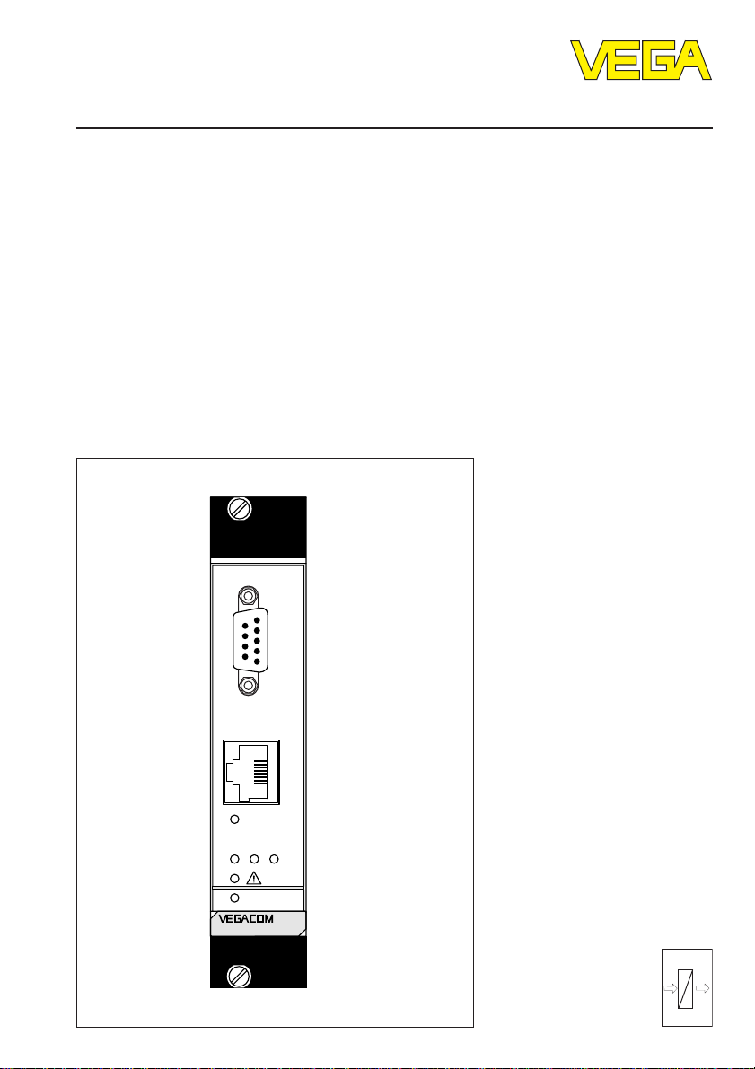
VEGACOM 558 Ethernet
Level and Pressure
PC
Ethernet
321
on
558
out
in
Page 2

Contents
Safety information ........................................................................ 2
Note Ex area ................................................................................ 2
1 Product description
1.1 Function ................................................................................. 4
1.2 Configuration ........................................................................ 4
1.3 Technical data ....................................................................... 5
1.4 Dimensions ........................................................................... 7
2 Mounting..................................................................................... 8
3 Electrical connection
3.1 Connection instruction ......................................................... 9
3.2 Wiring plan ............................................................................ 9
4 Communication with VEGACOM
4.1 Ways to connect ................................................................ 10
4.2 Adjustment software .......................................................... 11
Contents
5 Configuration of VEGACOM 558
5.1 Adjust communication mode with VVO ............................ 15
5.2 IP address.......................................................................... 16
5.3 Connection via modem ...................................................... 17
5.4 VEGACOM 558 on DISBUS .............................................. 19
5.5 Real time clock ................................................................... 20
5.6 Activate password protection ........................................... 21
Safety information
Please read this manual carefully, and also take
note of country-specific installation standards
(e.g. the VDE regulations in Germany) as well
as all prevailing safety regulations and accident prevention rules.
For safety and warranty reasons, any internal
work on the instruments, apart from that involved in normal installation and electrical connection, must be carried out only by qualified
VEGA personnel.
2 VEGACOM 558 Ethernet
Note Ex area
Please note the attached safety instructions
containing important information on installation
and operation in Ex areas.
These safety instructions are part of the operating instructions and come with the Ex approved instruments.
Page 3

Contents
6 VEGACOM 558 as Modbus / TCP server
6.1 Storage of measured values when
connected to DISBUS ........................................................ 23
6.2 Storage of contact inputs/outputs when
connected to DISBUS ........................................................ 26
6.3 Storage of measured values when
connected to LOGBUS ...................................................... 28
6.4 Storage of the contact outputs when
connected to LOGBUS ...................................................... 30
6.5 Format for transfer of measured values .......................... 32
7 VEGACOM 558 as web server
7.1 VEGACOM in the Internet .................................................. 33
7.2 Predefined web pages ...................................................... 33
7.3 Network settings ................................................................ 35
7.4 Web server settings .......................................................... 39
7.5 Send emails ........................................................................ 39
7.6 Language of VEGACOM 558 ............................................ 42
7.7 Real time clock ................................................................... 43
7.8 User Management ............................................................. 44
8 Your own html documents
8.1 Transfer html files ............................................................... 52
8.2 Structure of html files ......................................................... 56
8.3 Key words for output in html files ..................................... 58
9 Diagnosis .................................................................................. 61
Supplement A ................................................................................. 62
Supplement B ................................................................................. 68
VEGACOM 558 Ethernet 3
Page 4
1 Product description
Product description
1.1 Function
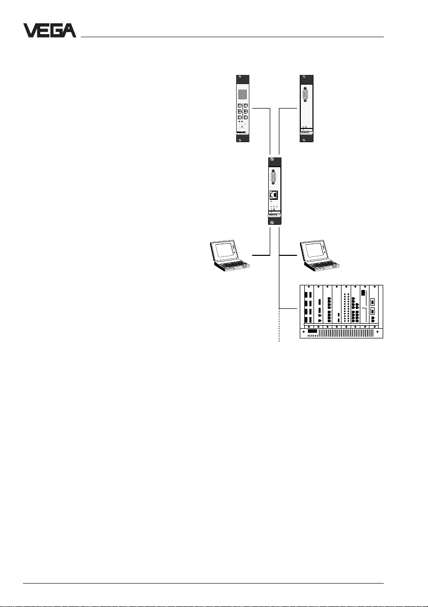
The VEGACOM 558 interface converter is
used for conversion of VEGA-specific
protocols of the DISBUS and LOGBUS into
the TCP/IP protocol. It enables the connection
of VEGA signal conditioning instruments
VEGAMET series 500 and 600 and the
VEGALOG 571 processing system, and
through this, the connection of VEGA transmitters to an Ethernet network. When connecting signal conditioning instruments, the
data of the VEGA protocol "DISBUS" are
used, with the processing system, the VEGA
protocol "LOGBUS" is used.
VEGACOM can be used as a web server,
making the measured values of the connected VEGA instruments available in html
format on the Ethernet. At the office level, the
measured values of VEGA instruments can
be displayed with an internet browser on
each computer connected to the network.
The data of VEGACOM 558 can also be
called up via the WWW. Furthermore, it is
possible to send emails containing measured
values at predefined times and dates. For
integration in process control or visualisation
systems, VEGACOM 558 provides a
Modbus / TCP server.
Network participants provided with the adjustment software VVO (VEGA Visual Operating) (e.g. service technicians) can adjust the
VEGA instruments via Ethernet. With the
visualisation software VV (Visual VEGA), it is
also possible to access via network connection VEGACOM 558 and thus the measured
values of the VEGA instruments.
Note:
To enable VEGALOG to work together with
VEGACOM 558, the CPU card of VEGALOG
must be equipped with the software version
1.30 or higher.
VEGAMET
500/600
VVO/
VV/
Webbrowser
%
100
+
-
OKESC
CONNECT
12
on
514
RS 232
LOGBUSDISBUS
PC
Ethernet
321
on
558
Ethernet
VEGACOM 558
VEGALOG
CPU
PC
on
571 CPU
VVO/
VV/
Webbrowser
Modbus / TCP
SPS / PLS
1.2 Configuration
VEGACOM 558 is designed in European size
(5 TE width) and can be mounted into:
- carrier BGT596
- VEGALOG carrier BGT LOG571
- housing type 505.
The electrical connection to the power supply,
DISBUS and LOGBUS is made with plug
connectors. On the front plate of VEGACOM
there are also:
- a nine-pole SUB-D plug (RS232) for direct
connection to a PC with adjustment software VVO (VEGA Visual Operating) or the
visualisation software VV (Visual VEGA)
- an RJ-45 connection for connection to an
Ethernet network.
4 VEGACOM 558 Ethernet
Page 5

Product description
1.3 Technical data
Power supply
Operating voltage U
Power consumption approx. 4 VA
Fuse 1 A, slow-blow
Electrical connection
Component multiple plug acc. to DIN 41 612, series F
Module in carrier
BGT 596 or BGT LOG571 suitable multipoint connector acc. to DIN 41 612
Housing type 505 via screw terminals max. 1 x 1.5 mm
Indicating elements
LEDs in front plate
- on (green) operating condition
- ! (red) failure indication
- Ethernet (green/red) status Ethernet (linked, TX, RX)
- 1 (green/red) save indication
- 2 (green/red) status LOGBUS
- 3 (green/red) status DISBUS
Measured data input DISBUS
Data transmission DISBUS (digital data transmission)
Connection cable connection via 48-pole multipoint connector
Max. cable length 1000 m
= 24 V AC (20 … 53 V), 50/60 Hz or
nom
= 24 V DC (20 … 72 V)
48-pole (d, b, z) with coding holes
with connection via standard technologies
2
2-wire standard cable (screened)
Measured data input LOGBUS
Data transmission LOGBUS (digital data transmission)
Connection cable connection via bus plug
RS 232 interface on front plate
Interface standard RS 232C
Cable length max. 15 m
Transmission rate in baud 9600, 19200, 38400, 57600
Transmission format 8 data bits, 1 stop bit, no parity
Plug in the front plate SUB-D plug connector, 9-pole, pins
VEGACOM 558 Ethernet 5
Page 6

Product description
Ethernet interface on the front plate (mode 10BaseT)
Interface standard Ethernet (IEEE802.3)
Line impedance 100 Ohm +/– 15 %
Cable type Ethernet-Patch cable category 5 (STP)
Wire cross-section 0.2 mm
2
No. of wires 4
Max. transmission rate 10 Mbits/s
Coding Manchester
Topology star
Max. segment length 100 m
Plug version 8-pole RJ45 plug
Frame-Format Ethernet Version 2
Ethernet interface on the front plate (mode 100BaseTX/Fast Ethernet)
Interface standard Ethernet (IEEE802.3)
Line impedance 100 Ohm +/– 15 %
Cable type Ethernet-Patch cable category 5 (STP)
Wire cross-section 0.2 mm
2
No. of wires 4
Max. transmission rate 100 Mbits/s
Coding Manchester with 4B/5B procedure
Topology star
Max. segment length 100 m
Plug version 8-pole RJ45 plug
Frame-Format Ethernet Version 2
Electrical protective measures
Protection
- not mounted IP 00
- in carrier BGT596
or BGT LOG571
- front side completely equipped IP 40
- upper and lower side
BGT596 IP 00
BGT LOG571 IP 20
- wiring side IP 00
- in housing type 505
- front side IP 40
- other sides IP 30
Protection class II (in housing type 505)
Overvoltage category II
Electrical separating measures
Reliable separation acc. to VDE 0106, part 1 between power supply, LOGBUS, DISBUS,
RS 232 and Ethernet
- reference voltage 250 V
- test voltage 2 kV
6 VEGACOM 558 Ethernet
Page 7
Product description
CE conformity
VEGACOM 558 meet the protective regulations of EMC taking the following standard into
consideration:
Emission EN 61 326: 1997/A1: 1998 (class A)
Susceptibility EN 61 326: 1997/A1: 1998
The protective regulations of the low voltage directive are fulfilled acc. to the EN standard
EN 61 010 - 1: 1993
Ambient conditions
Permissible ambient temperature -20 °C … +60 °C
Storage and transport temperature -20 °C … +85 °C
Mechanical data
Series module unit for carrier BGT596,
BGT LOG571 and housing type 505
Dimensions, not mounted W = 25.4 mm (5 TE), H = 128.4 mm, D = 166 mm
Weight approx. 550 g
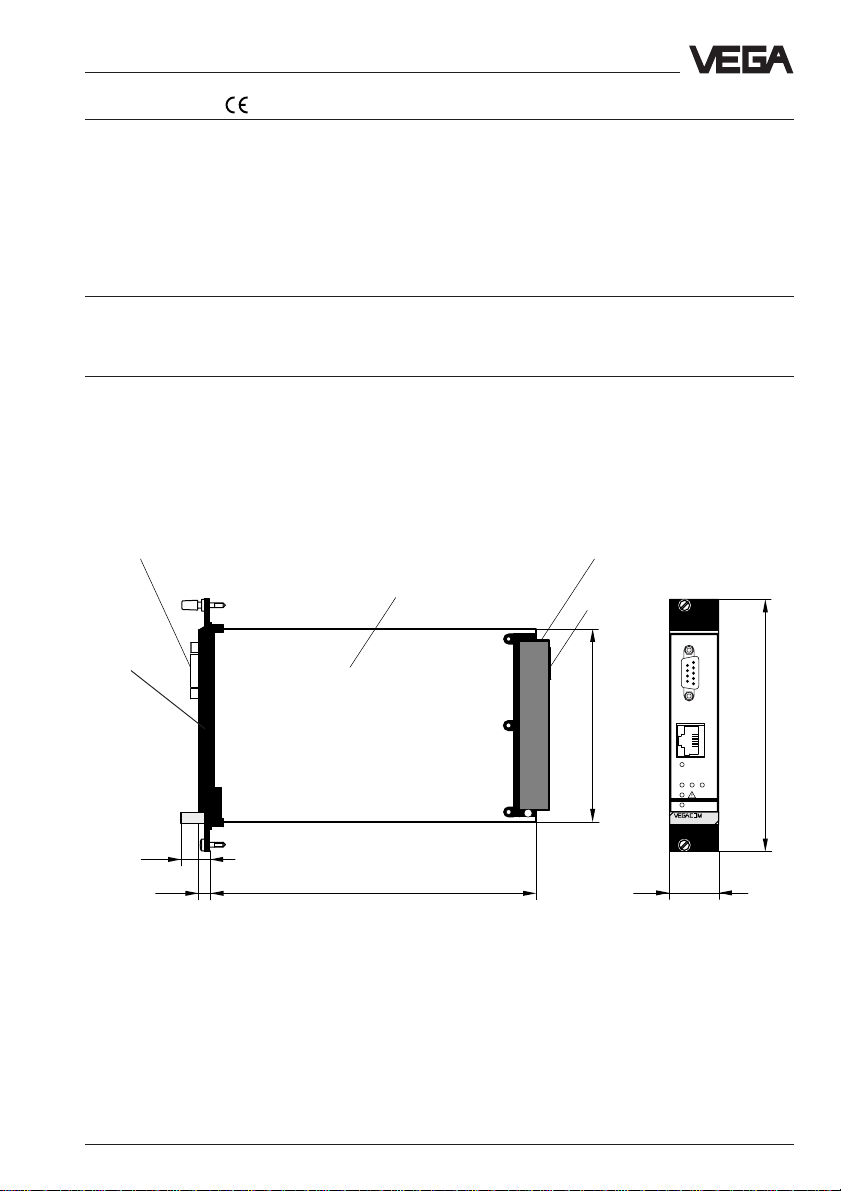
1.4 Dimensions
RS 232C interface
Ethernet
interface
(RJ45)
15
Circuit board 100 x 160 x 1.5
European size
1625,5
Multiple plug
LOGBUSplug
100
5 TE
Ethernet
on
25,4
PC
128,4
321
558
VEGACOM 558 Ethernet 7
Page 8
2 Mounting
Mounting
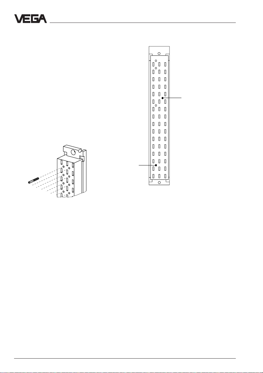
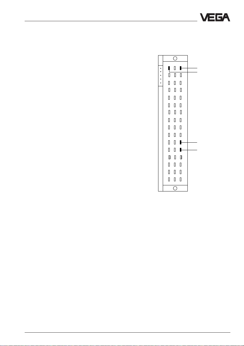
Coding
A mechanical coding system avoids later
interchanging of various module cards in the
carrier or in the housing type 505.
The coding system consists of:
- two coded pins in the multipoint connector
- two holes in the multiple plug of
VEGACOM.
The coded pins are attached to the module
(multipoint connector). The multipoint connector is equipped with the coded pins by the
user according to the following illustrations.
Coded pin
z b d
a c
o 1 o
o 3 o
o 5 o
o 7 o
o 9 o
o11o
o13o
o15o
o17o
o19o
o21o
o23o
o25o
o27o
a29
Positioning of the coded pins on the multipoint connector
o29o
o31o
c11
8 VEGACOM 558 Ethernet
Page 9
Electrical connection
3 Electrical connection
3.1 Connection instruction
Safety information – Qualified
personnel
Instruments which are not operated with
protective low voltage or DC voltage must
only be connected by qualified personnel.
This also applies to the configuration of
measuring systems planned for Ex environment.
As a rule, do all connecting work in the complete absence of line voltage. Always switch
off the power supply before you carry out
connecting work. Protect yourself and the
instruments.
3.2 Wiring plan
LOGBUS
(data from
VEGALOG 571)
2
4
6
8
10
12
14
16
18
20
22
24
26
28
30
32
d b z
–
+
+
DISBUS
(data from
–
VEGAMET)
VEGACOM 558 Ethernet 9
Page 10
4 Communication with VEGACOM
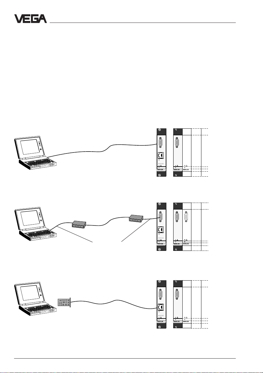
4.1 Ways to connect
There are a number of ways to enable communication with VEGACOM 558:
- a direct standard connection with the PC
(RS232)
- a standard connection via modems and
telephone network with the PC (RS232)
- a connection via a network (Ethernet)
- a connection via internet
Communication with VEGACOM
RS 232 (VVO, VV)
RS 232 (VVO, VV)
Ethernet (HTTP, FTP,
Telnet, VVO, VV)
Ethernet card
Modem
RS 232 connection cable
Telephone
network
RS 232 cable
Cross-over cable
Local
modem
PC
Ethernet
321
on
558
VEGACOM
PC
Ethernet
321
on
558
VEGACOM
PC
Ethernet
321
on
558
on
571 CPU
on
571 CPU 571 CPU
on
571 CPU
571 EV
571 EV
VEGACOM
10 VEGACOM 558 Ethernet
Page 11
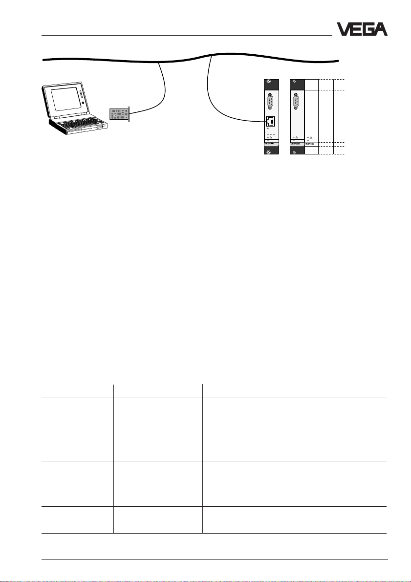
Communication with VEGACOM
Ethernet (HTTP, FTP,
Telnet, VVO, VV)
Ethernet
PC
Ethernet card
Ethernet-Patch cable
category 5 (STP)
Ethernet
321
on
558
VEGACOM
on
571 EV
571 CPU
4.2 Adjustment software
There are two ways to adjust VEGACOM 558
with the adjustment software VVO, either via
the RS232 interface or via the Ethernet interface. In both cases, VVO version 2.80 or
higher is necessary.
For settings on VEGACOM 558 relating to
certain internet services (e.g. web server,
Mail-Client, etc.), an internet browser, e.g.
Internet Explorer or Netscape Communicator,
must be used instead of VVO. Adjustment
with an Internet browser, however, requires
that VEGACOM 558 and the PC be connected via a network (Ethernet).
Software Connection technology Activities
VVO (VEGA - standard (RS232) - complete configuration and parameter setting
Visual Operating) - Ethernet of the connected instruments with LOGBUS
version 2.8 - modem connection and DISBUS (VEGALOG and signal condior higher tioning instruments)
- provide Ethernet access
- load html pages into VEGACOM
Internet browser - Ethernet - configuration of Mail-Client, Web server,
Diagnosis, …
or Netscape - show html pages of VEGACOM
Communicator - generate and send emails
Ping - Ethernet - diagnosis help (search and check network
participants)
VEGACOM 558 Ethernet 11
Page 12
Configuration of VEGACOM 558
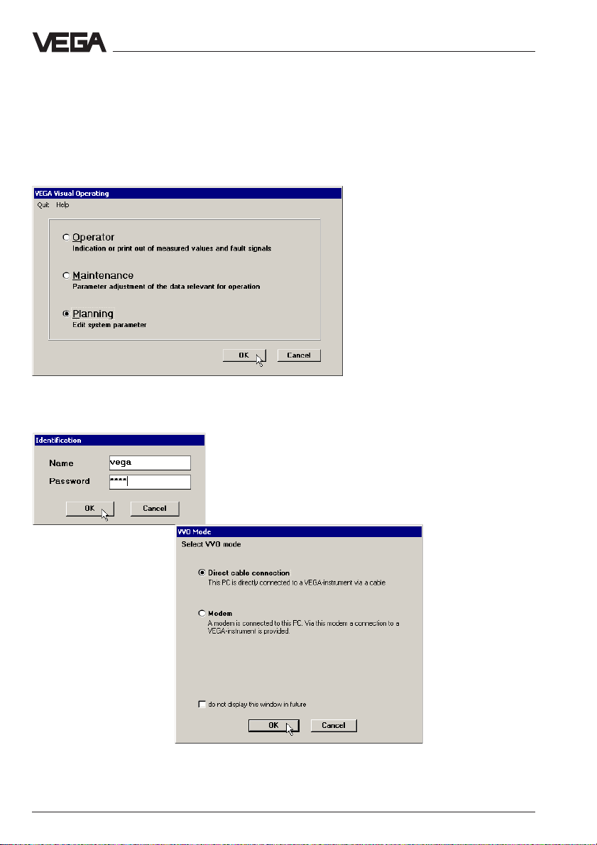
5 Configuration of VEGACOM 558
The configuration of the instrument is done with the adjustment software
VVO (VEGA Visual Operating), version 2.8 or higher, and can be realised via the standard serial interface or Ethernet connection. Connect
VEGACOM 558 to the PC (as described in chapter "4.1 Ways to connect"). Start VVO and choose Planning.
Enter in each of the following fields (name and password) vega and
then choose mode Direct cable connection.
12 VEGACOM 558 Ethernet
Page 13
Configuration of VEGACOM 558
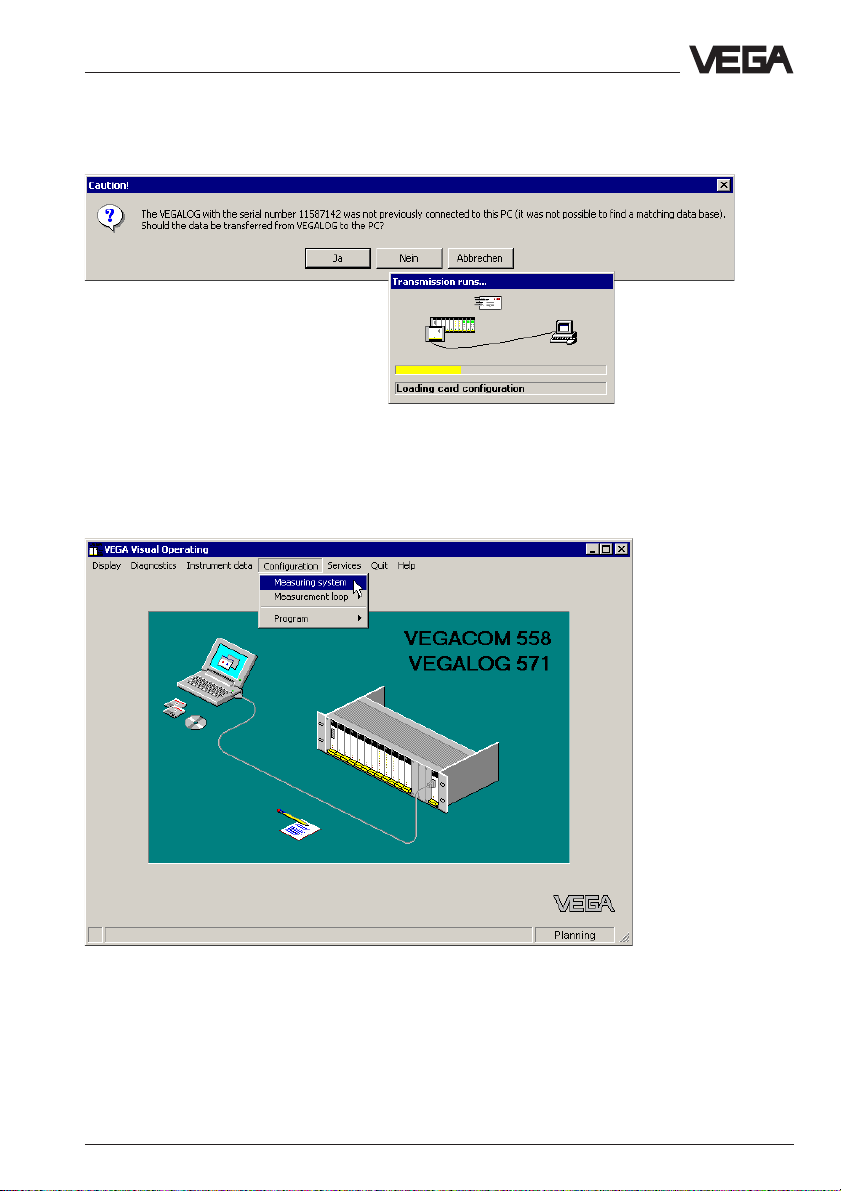
If necessary, confirm the following message (if VEGALOG or VEGAMET
was already previously connected to VVO, another message appears)
and wait until data transmission is finished.
VVO now shows the connected instrument, in this case a VEGALOG with
a VEGACOM 558 which is connected via the standard serial interface to
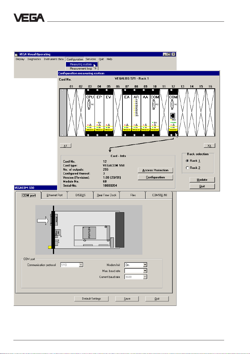
the PC. Click to Configuration and to Measuring system.
VEGACOM 558 Ethernet 13
Page 14

Configuration of VEGACOM 558
Click in the following window to VEGACOM 558 and then the button
Configuration (VEGACOM can, however, be located in other positions
than shown here).
The following image shows the configuration window of VEGACOM 558.
By clicking different registers, all parameters of VEGACOM 558 can be
reached.
14 VEGACOM 558 Ethernet
Page 15
Configuration of VEGACOM 558
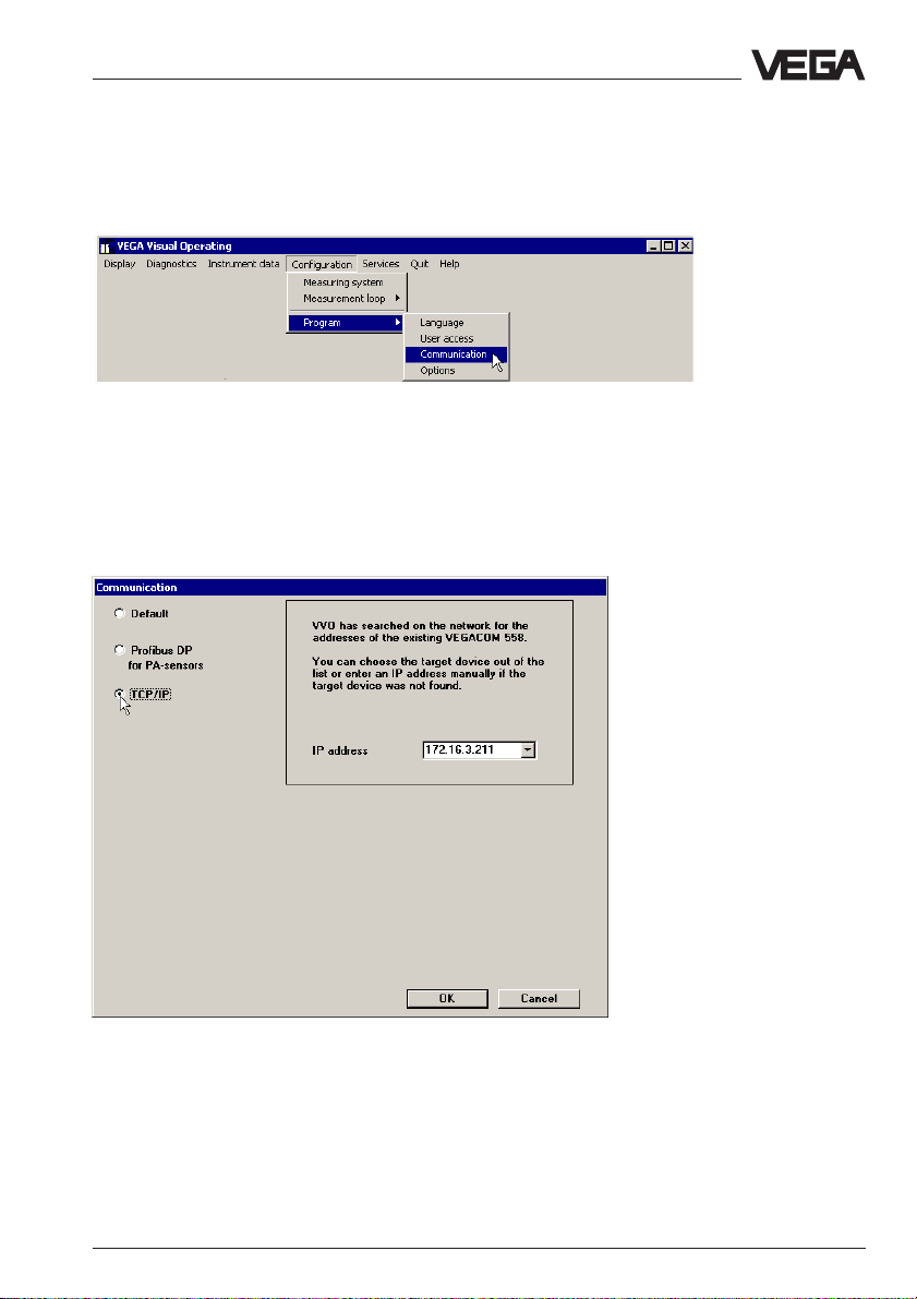
5.1 Adjust communication mode with VV O
During installation, VVO is set to "serial communication" (standard). For
access via Ethernet to VEGACOM, VVO must be switched over. Click in
the VVO main window to Configuration > Program > Communication.
Choose in the window "Communication" TCP/IP. VVO searches the network for existing VEGACOMs and enters the result (IP addresses) in
the list box. Then the requested VEGACOM can be selected out of the
list. If it is not found by VVO (because it is probably switched off or not
already connected), the IP address must be entered manually. After
confirmation with OK, VVO searches the network and makes a connec-
tion to the instrument.
If a connection to a VEGACOM 558 (whose IP address has already
been entered) should be made at a later time, you only have to select it
from the list.
VEGACOM 558 Ethernet 15
Page 16
Configuration of VEGACOM 558
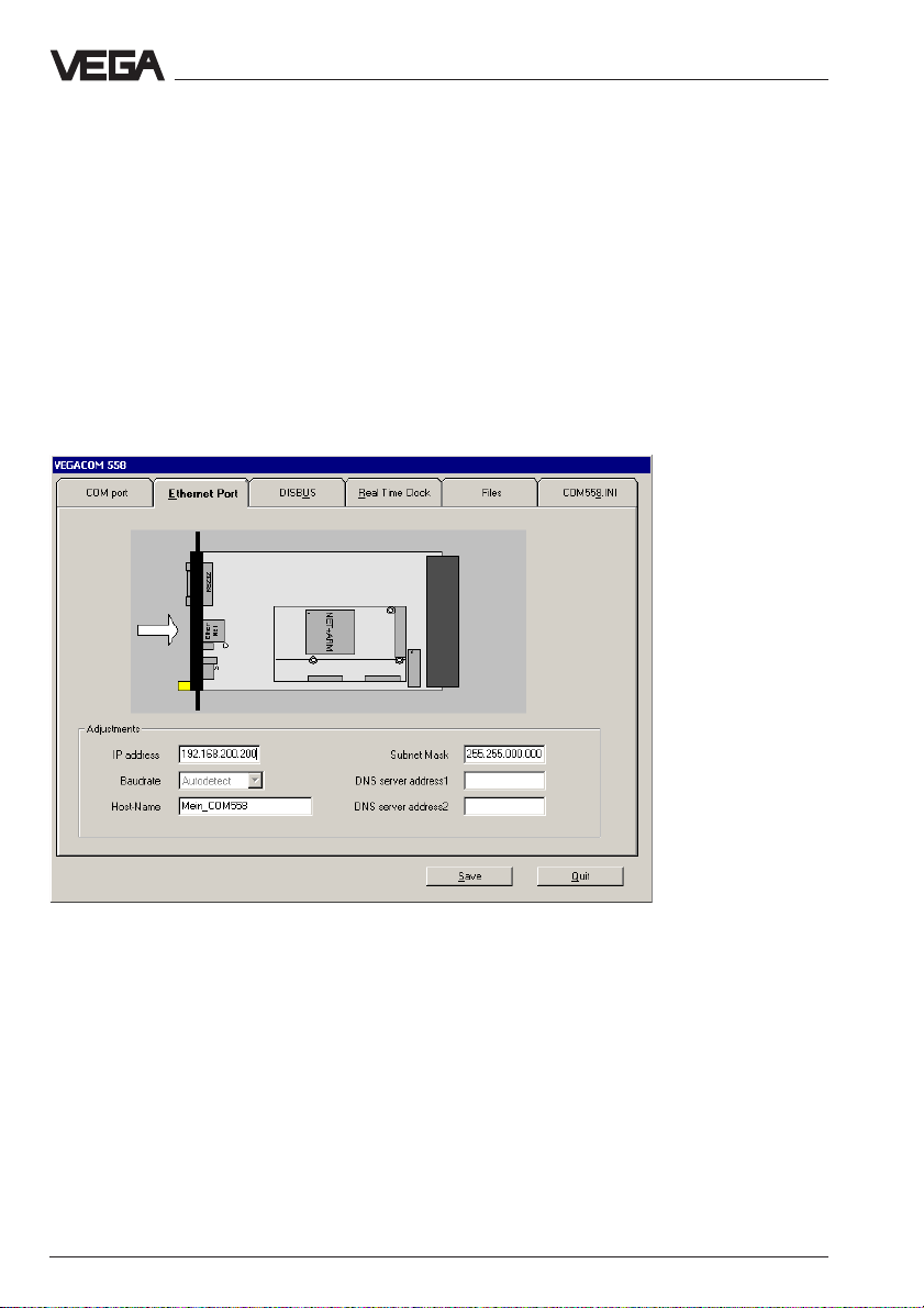
5.2 IP address
If the instrument is to be connected to the network, it must have an IP
address for identification on the net. As default, VEGACOM 558 has IP
address 192.168.200.200.
Generally, the system administrator assigns a unique IP address for
each network participant. To assign this address on VEGACOM 558,
move to the configuration window of VEGACOM (here it doesn’t matter if
a serial or a network connection exists). There you click the register
Ethernet Port. In the fields, you enter the IP address and a host name,
if necessary also the subnet mask and DNS server addresses. Make
sure that the host name does not contain special or blank characters.
The baud rate can remain at Autodetect. Then you have to Save. With
Quit (push twice) you return to the VVO main window.
16 VEGACOM 558 Ethernet
Page 17
Configuration of VEGACOM 558
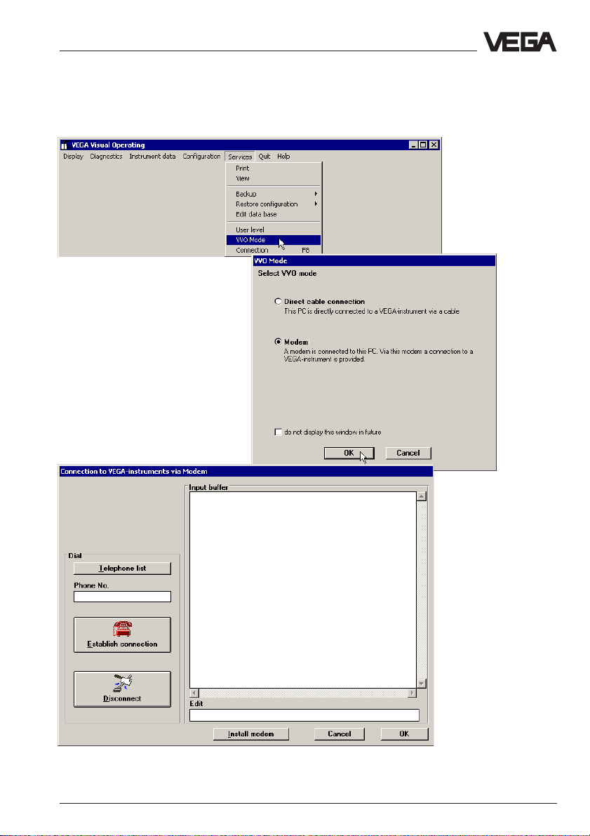
5.3 Connection via modem
If VEGACOM 558 is to be adjusted via modem, you have to adjust the
mode Modem (as shown in the following three images).
VEGACOM 558 Ethernet 17
Page 18
Configuration of VEGACOM 558
For modem operation, also note the settings in the configuration window
of VEGACOM. As default, the modem initialisation is switched on and the
baud rate is set to 9600. These settings relate to the local modem.
For detailed information on modem operation, see operating instructions
"Remote parameter adjustment".
18 VEGACOM 558 Ethernet
Page 19
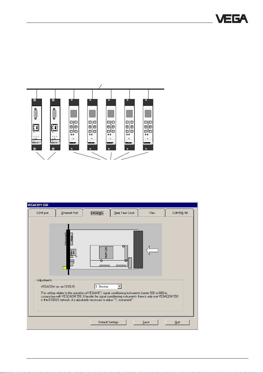
Configuration of VEGACOM 558
5.4 VEGACOM 558 on DISBUS
If VEGACOM 558 is operated in conjunction with VEGA signal conditioning instruments (e.g. VEGAMET 515, VEGAMET 614), it is a participant
on the DISBUS. Max. 15 VEGAMETs can be connected to the DISBUS,
in addition, two participants can be a VEGACOM 558.
DISBUS
PC
PC
%
%
%
100
100
+
-
Ethernet
Ethernet
321
on
on
558
CONNECT
321
on
558
+
-
-
OKESC
OKESC
CONNECT
on
513
on
513
%
100
100
+
-
OKESC
CONNECT
on
513
%
100
+
+
-
OKESC
CONNECT
OKESC
CONNECT
on
513
513
VEGACOM 558 (max. 2) Signal conditioning instru-
ments (max. 15)
All DISBUS participants must be addressed (1 … 15). On VEGACOM
558, this is done in the configuration window (1. device or 2. device).
VEGACOM 558 Ethernet 19
Page 20
Configuration of VEGACOM 558
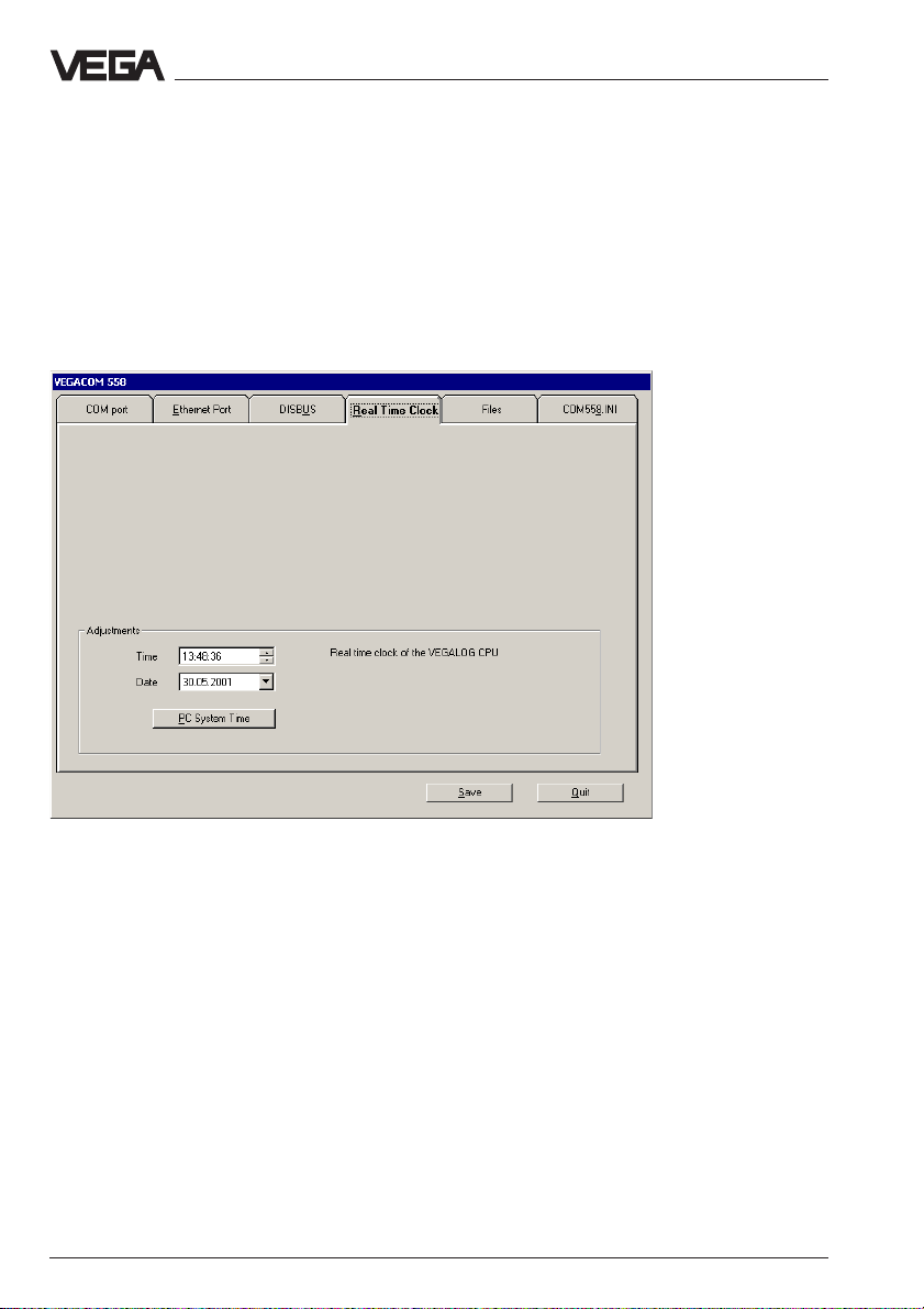
5.5 Real time clock
Since VEGACOM 558 can send time-controlled emails, the current time
must be available. In the CPU card of VEGALOG 571 there is a batterybuffered real time clock which is used by VEGACOM. In the illustrated
configuration window, you can set time and date manually or they can
be transferred with the button PC system time from the PC to the RAM
memory of the CPU card.
With Save, the time is permanently saved and and remains even in case
of mains failure.
Note:
If VEGACOM 558 is used in conjunction with DISBUS, no buffered real
time clock is available. After a supply interruption to VEGACOM, the time
must be readjusted.
20 VEGACOM 558 Ethernet
Page 21
Configuration of VEGACOM 558
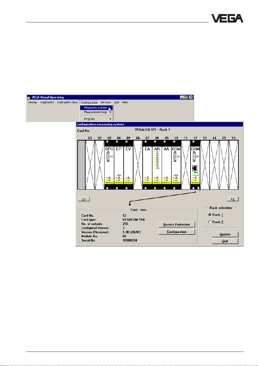
5.6 Activate password protection
To avoid unauthorised access to VEGACOM 558 and the connected
processing systems VEGALOG or VEGAMET, they can be protected
by a password. Especially when VEGACOM is adjusted via network
and is therefore accessible to each network participant, it can be important to preclude unauthorised adjustment. Click to Configuration >
Measuring system, in the window "Configuration Measuring system"
you click to the VEGACOM 558 and then to Access protection.
VEGACOM 558 Ethernet 21
Page 22
Configuration of VEGACOM 558
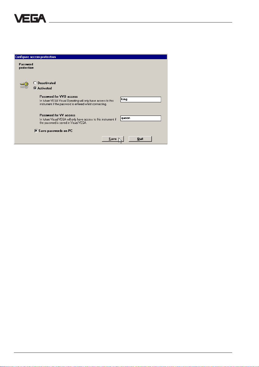
In the following window, you have to choose Activated and enter a
password for access with VVO as well as with VV (adjustment software
Visual VEGA). Then Save the setting.
However, the access protection is not yet activated, and only with the
next VVO start (and with switch-over of the communication mode from
standard to network and vice versa) will you be asked to enter the
password.
22 VEGACOM 558 Ethernet
Page 23
Data image in VEGACOM 558
6 VEGACOM 558 as Modbus / TCP server
VEGACOM 558 collects measured values of
the VEGAMET 513, 514, 515 and 614 signal
conditioning instruments (via DISBUS) or
VEGALOG 571 (via LOGBUS) and stores
them temporarily for collection via MODBUS /
TCP.
The way the measured values are stored in
the temporary storage of VEGACOM 558 for
the higher-priority processing system depends on the selected configuration. It depends on whether VEGACOM 558 is
connected to DISBUS or LOGBUS.
VEGACOM 558 follows the "Open MODBUS /
TCP Specification" release 1.0 from Schneider Electric. This standard is supported by
many process control systems, remote IO’s,
visualisation programs and OPC servers.
Note:
When connecting to DISBUS, the storage of
measured values can be determined additionally via the HTML configuration page
"General".
Beside the measured values, it is also possible to call up the status of the contact inputs
and outputs via VEGACOM 558.
Call up of the measured values via:
- Function code 04 (= Read Input Registers)
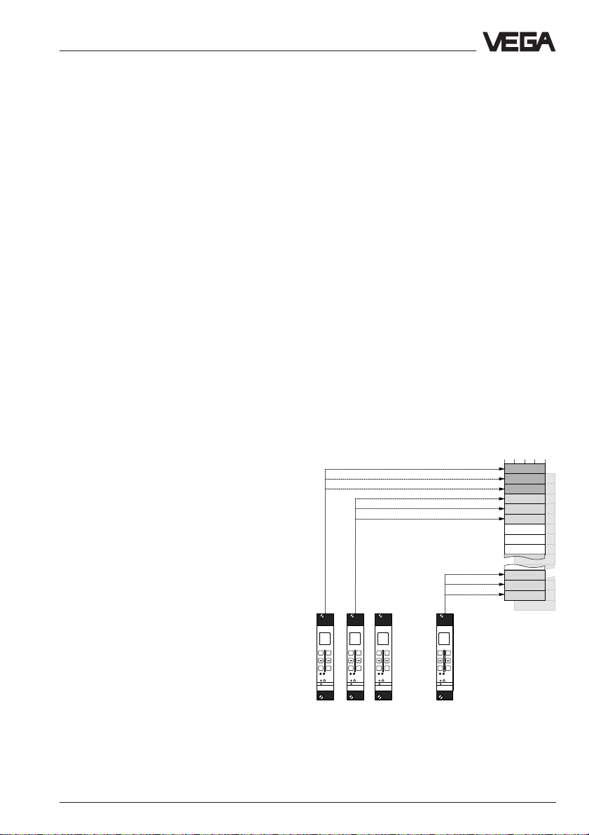
6.1 Storage of measured values when connected to DISBUS
The addressing of the measured values for
Modbus systems is "word-oriented". In
VEGACOM 558, a measured value is represented by two words, the first word includes
the real measured value, the next higher
word the associated status information. In the
standard, the term "register word” is also
used instead of the term "word”. The addressing is done via existing library calls of
the process control system (e.g. Modicon).
As already mentioned, the storage of measured values for VEGAMET signal conditioning
instruments can be influenced by the user.
For this purpose, a connection to VEGACOM
558 must first be provided via a web
browser. By activating the entry "DCS 1-7
from MET 1, …" in the section "storage of
measured values for MODBUS / TCP” in the
HTML page "General", the measured values
are saved in rising sequence acc. to the
VEGAMET addresses.
all measured values
from VEGAMET #1
all measured values
from VEGAMET #2
Call up of the switching conditions via:
- Function code 01 (= Read Coil Status) or
alternatively via
ESC OK
VEGAMET
%
100
+
-
CONNECT
!
on
513
all measured values
from VEGAMET #15
%
100
+
-
ESC OK
CONNECT
!
on
VEGAMET
513
Temporary memory
of VEGACOM 558
- Function code 02 (= Read Input Status).
%
%
100
100
+
+
-
-
ESC OK
ESC OK
CONNECT
CONNECT
!
!
on
on
VEGAMET
VEGAMET
513
513
Grouping of measured values acc. to VEGAMET
addresses
VEGACOM 558 Ethernet 23
Page 24
Data image in VEGACOM 558
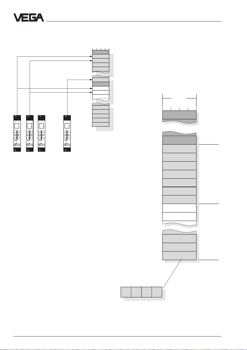
If the entry "DCS 1 from MET 1-15, …" is
activated, the measured values will be
grouped acc. to DCS indices or channels.
all DCS outputs with index =1
all DCS outputs with index =2
%
100
+
-
ESC OK
CONNECT
!
on
VEGAMET
513
Grouping of measured values acc. to DCS indices or
channels
-
ESC OK
VEGAMET
%
%
100
100
+
+
-
ESC OK
CONNECT
CONNECT
!
!
on
on
VEGAMET
513
513
ESC OK
VEGAMET
%
100
+
-
CONNECT
!
on
513
Temporary memory
VEGACOM 558
Addressing of measured values when
connected to DISBUS
With grouping acc. to VEGAMET address
(DCS 1 from MET 1, …)
Organisation of the temporary memory for
VEGAMET 513, 514, 515 or 614 signal conditioning instruments
Register
address
in
Modicon
30001
30013
30015
30017
30019
30021
30023
30025
30027
30029
30031
Temporary memory
in VEGACOM 558
4 Byte
reserved
reserved
DCS output 1
DCS output 2
DCS output 3
DCS output 4
DCS output 5
DCS output 6
DCS output 7
DCS output 1
DCS output 2
VEGAMET
with DISBUS
address 1
VEGAMET
with DISBUS
address 2
Sta-
tus
DCS output 5
DCS output 6
DCS output 7
VEGAMET
with DISBUS
address 15
Note:
A complete overview of the process image of
30219
30221
30223
Meas. value
High-
Byte
Grouping of measured values acc. to VEGAMET
addresses on VEGAMET 513, 514, 515 or 614
Low-
Byte
Add. info
Meas.
unit
VEGACOM 558 can be found in supplement
A at the end of this operating instructions
manual
24 VEGACOM 558 Ethernet
Page 25

Data image in VEGACOM 558
Grouping acc. to DCS indices (DCS 1 from MET 1-15, … ):
Organisation of the temporary memory for
VEGAMET 513, 514, 515 or 614 signal conditioning instruments
Register
address
in
Modicon
30001
30003
30005
30007
30009
30031
30033
30035
30037
30039
30215
30217
30219
30221
30223
Temporary memory in
VEGACOM 558
4 Byte
reserved
DCS output 1
DCS output 1
DCS output 1
DCS output 1
DCS output 1
reserved
DCS output 2
DCS output 2
DCS output 2
DCS output 7
DCS output 7
DCS output 7
DCS output 7
DCS output 7
VEGAMET
with
DISBUS
address =
1
2
3
4
15
1
2
3
11
12
13
14
15
Meas. value
High-
Byte
Low-
Byte
Add. info
Meas.
unit
Sta-
tus
Grouping of measured values acc. to DCS indices for
VEGAMET 513, 514, 515 or 614
Note:
A complete overview of the process image of VEGACOM 558 can be found in supplement A at
the end of this operating instructions manual
VEGACOM 558 Ethernet 25
Page 26

Data image in VEGACOM 558
6.2 Storage of contact inputs/outputs when connected to DISBUS
Beside the previously described measured
values, it is also possible to transmit switching conditions of the VEGAMET 513, 514 and
515 signal conditioning instruments via
VEGACOM 558.
This particularly includes:
- status of the contact inputs (key switch
position, etc.)
- status of the contact outputs (relay or tran-
sistor outputs)
16 register bits from VEGAMET #1
In contrast to the image of the measured
values, the image of the switching status is
"bit oriented". In the standard, these status
bits are also called register bits. The addressing of the register bits for Modbus
systems is "bit oriented". In VEGACOM 558,
a switching status is represented as register
bit, whereby all available information of a
VEGAMET is saved in an associated block of
16 register bits. The storage of a 16 register
bit block within VEGACOM 558 is controlled
via the setting of the DISBUS address on
VEGAMET. The addressing by means of the
control system is normally done by existing
library calls of a process control system
(.e.g. Modicon).
16 register bits from VEGAMET #2
16 register bits from VEGAMET #15
Temporary memory
ESC OK
VEGAMET
%
100
+
-
CONNECT
!
on
513
VEGACOM 558
-
ESC OK
VEGAMET
%
100
+
CONNECT
!
on
513
ESC OK
VEGAMET
%
%
100
100
+
+
-
-
ESC OK
CONNECT
CONNECT
!
!
on
on
VEGAMET
513
513
Image of the switching status in VEGACOM 558 for
VEGAMET 513, 514, 515 or 614
26 VEGACOM 558 Ethernet
Page 27

Data image in VEGACOM 558
Addressing of the switching conditions
when connected to DISBUS
Register
address
in
Modicon
10001
10002
10003
10004
10005
10006
10007
10008
10009
10010
10011
10012
10013
10014
10015
10016
10017
10018
10019
Temporary memory in
VEGACOM 558
1 BIT
Input contact 2
Input contact 1
reserved
reserved
reserved
reserved
reserved
Status: Inputs
Relay contact 1
Relay contact 2
Fail safe relay
reserved
reserved
reserved
reserved
Status: Outputs
Input contact 2
Input contact 1
reserved
VEGAMET
with
DISBUS
address =
1
VEGAMET
with
DISBUS
address =
2
If you imagine the 16 register bits belonging
to a VEGAMET as one 16 bit word, the
following graphical repesentation results.
Status of
inputs
Switching
status of
input
no.:
1.
Byte
Status of
outputs
12
456701234567Bit
2.
Byte
Switching
status of
output no:
The meaning of the individual bits is defined
as follows:
Status of inputs:
0 = all inputs OK
1 = input status not available (no inputs
configured or VEGAMET not available)
Switching status of inputs 1 and 2:
0 = input contact is open
1 = input contact is closed
Status of outputs:
0 = all outputs OK
1 = output status not available (no outputs
configured or VEGAMET not available)
123
0123
Switching status of outputs 1, 2 and 3 (output
3 corresponds to fail safe relay):
0 = relay is deenergised
1 = relay is energised
15
10238
10239
10240
reserved
reserved
Status: Outputs
VEGAMET
with
DISBUS
address =
Note:
Addressing of the switching conditions in VEGACOM
558 for VEGAMET 513, 514, 515 or 614
A complete overview of the process images
on the switching status of VEGACOM 558
can be found in supplement B at the end of
this operating instructions manual.
VEGACOM 558 Ethernet 27
Page 28

Data image in VEGACOM 558
6.3 Storage of measured values when connected to LOGBUS
The addressing of measured values for
Modbus systems is "word-oriented". In
VEGACOM 558, a measured value is represented by two words, whereby the first word
includes the real measured value, the next
higher word the associated status information. In the standard, the term "register word”
is also used instead of the term "word”. The
addressing is done via existing library calls
of a PLC (e.g. Modicon).
DCS output 1
DCS output 2
DCS output 3
VEGALOG 571 can administrate up to 255
measurement loops. For the transfer of the
measured values of a measurement loop,
VEGALOG provides up to 255 DCS outputs.
One or several DCS outputs with any index
can be assigned to each measurement loop.
The configuration of VEGALOG 571 is done
with the VEGA adjustment software VVO. The
selected PC/DCS output defines where the
appropriate measured values can be collected from the temporary memory of
VEGACOM 558.
Meas.
value
x
!
on
VEGALOG
Meas.
Meas.
value
y
PC
571
value
DCS output 255
Temporary memory of
VEGACOM 558
Measured value image when connected to
VEGALOG 571
28 VEGACOM 558 Ethernet
Page 29

Data image in VEGACOM 558
Addressing of measured values when
connected to LOGBUS
The measured value image when connected
to LOGBUS is always sorted acc. to the DCS
outputs, the following illustration shows the
addressing of the temporary memory via
Modbus.
Register
address
in
Modicon
30001
30003
30005
30007
30009
30011
30013
30015
30017
30505
30507
30509
Meas.
value
High-
Byte
Low-
Byte
Add. info
Meas.
unit
Temporary memory of
VEGACOM 558
4 Byte
DCS output 1
DCS output 2
DCS output 3
DCS output 4
DCS output 5
DCS output 6
DCS output 7
DCS output 8
DCS output 9
DCS output 253
DCS output 254
DCS output 255
Sta-
tus
Addressing of the measured value when connected to
LOGBUS
Note:
A complete overview of the process image of
the measured values of VEGACOM 558 can
be found in supplement A at the end of this
operating instructions manual.
VEGACOM 558 Ethernet 29
Page 30

Data image in VEGACOM 558
6.4 Storage of the contact outputs when connected to LOGBUS
Beside the previously described measured
values, it is also possible to transfer
switching conditions of the VEGALOG 571
processing system via VEGACOM 558.
This particularly includes:
- status of the contact outputs of the AR
cards (relay contacts)
- status of the contact outputs of the AT
cards (transistor outputs)
Output status of the output card on
module #1
In contrast to the imaging of measured
values, the imaging of switching status is
done "bit-oriented". In the standard, these
status bits are also called "register bits". The
addressing of the register bits for Modbus
systems is therefore "bit-oriented". In
VEGACOM 558, a switching status is
represented by one register bit, whereby all
available information of a VEGALOG output
card type AR or AT is saved within an
associated block of 16 register bits. The
storage of a 16 register bit block within
VEGACOM 558 depends on the module
position in VEGALOG 571.
The addressing by the control system is
done via existing library enquiries of a
process control system (e.g. Modicon).
Output status of the output
card on module #32
Temporary memory of
VEGACOM 558
PC
!
on
VEGALOG
571
Image of the switching status in VEGACOM 558 for
VEGALOG 571
30 VEGACOM 558 Ethernet
Page 31

Data image in VEGACOM 558
Addressing of the output status when
connected to LOGBUS
The image of the output status when
connecting to VEGALOG is always sorted
acc. to the module numbers of the output
cards, the following illustration shows the
addressing of the temporary memory via
Modbus.
Register
address
in
Modicon
10001
10002
10003
10004
10005
10006
10007
10008
10009
10010
10011
10012
10013
10014
10015
10016
10017
Temporary memory of
VEGACOM 558
1 BIT
Output 9
Output 10
reserved
reserved
reserved
reserved
reserved
Status: Card
Output 1
Output 2
Output 3
Output 4
Output 5
Output 6
Output 7
Output 8
Output 9
Values of
VEGALOG
Card on
module =
If you image the 16 register bits belonging to
a module card as one 16 bit word, the
following graphical representation results:
Status of the
output card
Switching status of output no:
8910
01234567Bit
1.
Byte
The meaning of the individual bits is defined
as follows:
Status of the output card:
0 = OK
1 = no values of the output card available
(no outputs configured or card not
available)
Switching status of the inputs with AR or AT
cards:
0 = relay deenergised
1
1 = relay energised
Note:
A complete overview of the process image of
the switching status of VEGACOM 558 can
be found in supplement B at the end of this
operating instructions manual.
4567
2.
Byte
123
4567
0123
50910510
51010511
51110512
Output 6
Output 7
Output 8
Values of
VEGALOG
Card on
module =
32
Addressing of the switching status in VEGACOM 558
for VEGALOG 571
VEGACOM 558 Ethernet 31
Page 32

Format for transfer of measured values
6.5 Format for transfer of measured values
Measured values and DCS values
The measured values of the VEGA
processing systems (VEGAMET or
VEGALOG) connected to VEGACOM 558 are
imaged on the input registers of Modicon 584
as described in chapter 6.1 and 6.3. In
VEGACOM 558, they are available for
collection as so-called DCS values.
One DCS value covers two register
addresses, this means that it consists of two
double words, i.e. 4 bytes.
A complete overview of the image of the DCS
values in the input registers of Modicon can
be found in supplement A of this operating
instructions manual.
Structure of a measured value
Measured values of VEGALOG or VEGAMET
are transferred to VEGACOM 558 as signed
data comprising 2 octets. This means, that
the value range is max. +32.768 to -32.767.
Structure of a DCS value
A single DCS value in VEGACOM 558
consists of 4 octets and consists of the
following:
DCS value
Meas. value Add. info
The octet for the measuring unit is not
presently used and is always filled with the
value zero.
The status describes the condition of the two
associated measured value octets. The
contents of the measured value octet is only
valid if the assigned status has the value
zero.
If you have a status value unequal zero, the
status value and the associated value in the
measured value field must be taken into
account for a detailed failure diagnosis. The
following list explains the possible errors:
Status Meas. Meaning
value
0x00 0x XXXX valid meas. value
0x01 0x XXXX simulated meas. value
(only with VEGAMET
509 and 512)
0x80 0x XXXX old meas. value
(probably interrupted
connection)
0xFE 0x0000 no measured value
available (not
configured)
Octet 1 Octet 2 Octet 3 Octet 4
0xFF 0xFFFF no VEGAMET or
VEGALOG connected
High-Byte Low-Byte
Maßeinheit
Status
XX = type of error
The real measured value has a length of 2
octets and is signed, this means that the
value range is between +32768 and -32767.
In addition to the measured value,
0xFF 0x8000 failure message of an
individual
measurement loop
Type of error is not
defined
VEGACOM 558 provides one octet per DCS
value for measuring unit and another octet for
information on the actual status of the
measured value.
32 VEGACOM 558 Ethernet
Page 33

VEGACOM 558 as web server
7 VEGACOM 558 as web server
7.1 VEGACOM in the Internet
In this document, the function of VEGACOM 558 as web server within
the company network is described. If the Internet can be accessed
from the company network, VEGACOM can also function as web server
in the "World Wide Web". The necessary steps are not part of this document and will be generally done by the system administrator.
7.2 Predefined web pages
If VEGACOM 558 is participant on the network, the measured values of
VEGA sensors can be shown as a Web page and an online overview of
the VEGA measuring systems can be shown with an Internet browser.
For this purpose, VEGACOM contains already predefined web pages.
To show these web pages, the IP address of VEGACOM 558 must be
entered in the browser:
http://http://
xxx.xx.x.xxxxxx.xx.x.xxx
http://
xxx.xx.x.xxx = IP address
http://http://
xxx.xx.x.xxxxxx.xx.x.xxx
The browser then calls up the following html file (start page):
http://xxx.xx.x.xxx/vega/deutsch/process/index.htmhttp://xxx.xx.x.xxx/vega/deutsch/process/index.htm
http://xxx.xx.x.xxx/vega/deutsch/process/index.htm
http://xxx.xx.x.xxx/vega/deutsch/process/index.htmhttp://xxx.xx.x.xxx/vega/deutsch/process/index.htm
VEGACOM 558 Ethernet 33
Page 34

VEGACOM 558 as web server
The html file is configured such that all existing measurement loops,
sorted according to measurement loop names, are automatically displayed (splitting in several pages, switching over via the navigation
board below the measured value tables). By clicking the link Measured
values (No.) the measurement loops will be sorted according to the
number of the DCS output. The html file, however, is not accessible and
cannot be modified.
In addition, it is possible to make different VEGACOM settings and
modifications with the browser on the predefined web pages. For this
purpose, you will find links on the web page which will pass you on to
the appropriate page. For this purpose, the web page is provided with
links leading you the the respective page. These links are not visible on
the start page. The corresponding authorisation level of the user can be
released with "Release settings". Acc. to the factory setting, first of all
each user has access. First of all, everybody can access this function
by factory setting. By activating the user management, access can be
avoided (see chapter "User administration").
- network settings (host name, modification of the IP address,
subnetwork masks and Name-Server addresses)
- web server (updating intervals of the web pages, selection of differ-
ent web pages)
- setup mail server
- definition of the email messages (recipient, documents, transmitting
times)
- title of web pages, date and time in VEGACOM 558 (important for
time-controlled emails)
- language used by VEGACOM 558 (German or English)
- user management.
Note:
Some Internet browsers use the setting
"Use temporary internet files". This
causes the browser to read the file,
once it has been loaded, again and
again from the local hard drive. This
setting should be changed to ensure
that the HTML pages are always up-todate when calling up measured values
or the configuration pages of
Links
VEGACOM.
34 VEGACOM 558 Ethernet
Page 35

VEGACOM 558 as web server
7.3 Network settings
Like with the adjustment software VVO, the IP address, sub net mask,
host name1) and Name-Server addresses of VEGACOM 558 can be also
modified with the Internet browser. An IP address must be assigned
beforehand to VEGACOM so that it can be identified on the network (IP
address set as default: 192.168.200.200).
1)
Approved are alphanumierc characters and stroke. Do not use special characters.
VEGACOM 558 Ethernet 35
Page 36

VEGACOM 558 as web server
Subnets with VEGACOM 558
For the use of subnet masks with VEGACOM 558, the same rules as for
any Ethernet host apply. A host only processes telegrams whose destination addresses have full compliance with their own subnet. A specific
subnet is determined by its own IP address and the subnet mask. By
AND linking of IP address and subnet mask, you will get the appropriate subnet. In other words, all bit positions of the subnet mask set at "1",
determine the NetID, i.e. the subnet. The more bit positions used for the
determination of the NetID, the less combinations remain for the HostID.
Example:
VEGACOM 558 IP address: 192.168.200.1 (Class-C)
Standard masking (subnet mask): 255.255.255.0
This means for VEGACOM 558:
- VEGACOM 558 is in the subnet 192.168.200.0 (with max. 253 partici-
pants)
- VEGACOM 558 processes all telegrams on the Ethernet whose desti-
nation addresses start with 192.168.200.
- VEGACOM 558 itself can only transmit telegrams whose destination
addresses start with 192.168.200
Improved masking by e.g.: 255.255.255.128
This means for VEGACOM 558:
- By setting an additional bit in the subnet mask, the above-mentioned
subnet will be divided into two sections.
- VEGACOM 558 is now in subnet 192.168.200.0 (with max. 126 partici-
pants)
- VEGACOM 558 processes all telegrams on the Ethernet whose desti-
nation addresses are between 192.168.200.1 and 192.168.200.127.
- VEGACOM 558 itself can only drop off telegrams whose destination
addresses are between 192.168.200.1 and 192.168.200.127
36 VEGACOM 558 Ethernet
Page 37

VEGACOM 558 as web server
DNS by means of VEGACOM 558
If an application on a host (with VEGACOM 558 e.g. the Mail Client or
PING in TELNET window) tries to call another network participant with its
host name, the enquiring computer first has to know the IP address of
the destination computer.
The following steps are carried out:
Step 1:
The enquiring computer (VEGACOM 558) first asks via an ARP enquiry
for the MAC address of the entered DomainNameServers in the network. If available, the MAC address is returned.
Step 2:
The enquiring computer (VEGACOM 558) transmits a DNS telegram to
the DomainNameServer asking "which IP belongs to the host name xyz".
If the name server can resolve the host name, it will return the requested
IP directly as answer (probably the enquiry will be transferred to another name server).
Step 3:
The enquiring computer (VEGACOM 558) can now transmit the telegrams directly to the destination computer, the IP of which is known
now.
Note!!!
Conversion of the DNS configuration is currently only effective after a
restart of VEGACOM 558.
VEGACOM 558 Ethernet 37
Page 38

VEGACOM 558 as web server
Determine standard gateway for VEGACOM 558
From Rev. 1.10, VEGACOM 558 supports gateways or routers, whereby
these must be accessible within the subnet with regard to their IP address.
This means:
If a gateway address is entered in VEGACOM 558 which does not fit the
network address and the subnet, VEGACOM 558 will deactivate the
gateway support.
Function:
If a gateway address unequal 0 is entered in VEGACOM 558, the gateway functionality will be activated. The above-mentioned boundary condition, that the used address must be accessible within the subnet /
NetworkID, is a prerequisite.
Example:
If Host A (192.168.200.10) tries to reach a Host B in network
192.168.201, the protocol software in Host A determines by means of
the subnet entry that the destination host is in another network. If an IP
address is defined for a gateway, Host A will transmit an ARP enquiry to
the entered gateway to get its MAC address. Finally Host A transmits
the requested telegram to Host B, whereby the destination IP of the
destination computer (i.e. Host B) is entered, however, as destination
MAC, the destination IP of the gateway is used.
AB
192.168.200.10 192.168.201.4
Gateway / Router
E
t
h
e
r
n
e
t
1
9
2
.
1
6
8
.
2
0
0
192.168.200.1 192.168.201.1
192.168.200.2 192.168.201.6
E
t
h
e
r
n
e
t
1
0
2
.
8
6
1
.
2
9
1
By handing from one network to the other, the router replaces in the
received datagram the destination MAC address, either with the one of
the next router or with the one of the addressee (provided it can be
reached already directly).
On VEGACOM 558, the announcement of a router/gateway is carried
out exclusively by manual configuration.
38 VEGACOM 558 Ethernet
Page 39

VEGACOM 558 as web server
7.4 Web server settings
Here you can adjust the updating intervals of the html page. The empty
field can be used for a file created by yourself (see chapter "8 Your own
html documents"). The field list then always extends itself by one new
position by pushing the button "Save list". If you open a file entered into
the list via an Internet browser, the browser will call up this page cyclically acc. to the set updating period.
7.5 Send emails
First of all, the mail server must be set up so that VEGACOM 558 can
send emails. Enter the IP address of the mail server in the field "IP address of the outbox server (SMTP)" (you will get the IP address from the
network administrator). If the mail server has Internet access, it is possible to send emails worldwide.
VEGACOM 558 Ethernet 39
Page 40

VEGACOM 558 as web server
You must then define the mail recipients1) (in the field "email address”).
Any weekday or exact daily time can be entered as transmission time.
Instead of the entered documents
be sent, e.g.
layouts/val_name.htm layouts/val_name.htm
layouts/val_name.htm (see chapter "8 Your own html
layouts/val_name.htm layouts/val_name.htm
val_name.htmval_name.htm
val_name.htm , your own file can also
val_name.htmval_name.htm
documents").
If you want to send text files instead of the html file by email, you can
enter as attachment document var/pls.csv. Contrary to html files, this file
can be easily integrated into other documents for further processing
(registered…). For this kind of processing, VEGACOM 558 provides in
the directory "var/" two files which will be updated approx. every 5 s.
The file named
var/pls.csvvar/pls.csv
var/pls.csv includes DCS no., Tag names, measured
var/pls.csvvar/pls.csv
values and associated units of all measurement loops of the connected
VEGA system in ASCII format, whereby the individual fields are separated by ";".
The file named
var/rel.csvvar/rel.csv
var/rel.csv includes card number and switching status of
var/rel.csvvar/rel.csv
the associated relay output of all module cards for the connected VEGA
system in ASCII format, whereby the individual fields are separated by
";".
- pls.csv: Includes all measured values of the measurement loops incl.
DCS output number, TAG name and unit configured in the VEGA
processing system connected to VEGACOM 558.
Beispielplot:
#VERSION: 1.0
#FROM: COM558_Mast
#DATE: 05.07.2001 10:05
#FIELDS: Pls;Tag;Value;Unit
001;aa_temperatur ; 96.46;Lin%
002;Grenz_kapazitiv ; ——;Lin%
003;druck_kompakt ; ——;Lin%
1)
Approved are alphanumierc characters and stroke. Do not use special characters.
40 VEGACOM 558 Ethernet
Page 41

VEGACOM 558 as web server
- rel.csv: Includes the switching status of all relay outputs or
contact inputs (only with VEGAMET) of the measurement loop
including all card numbers for VEGALOG or DISBUS addresses
for VEGAMET configured in the VEGA processing system connected to VEGACOM 558.
Example plot on VEGALOG:
#VERSION: 1.0
#FROM: COM558_Mast
#DATE: 05.07.2001 10:14
#FIELDS: Card;R1;R2;R3;R4;R5;R6;R7;R8;R9;R10
01;-;-;-;-;-;-;-;-;-;02;-;-;-;-;-;-;-;-;-;03;-;-;-;-;-;-;-;-;-;04;-;-;-;-;-;-;-;-;-;05;-;-;-;-;-;-;-;-;-;06;-;-;-;-;-;-;-;-;-;07;0;0;0;0;0;0;0;0;0;0
Note: Only the "own" contact inputs will be displayed. If a
VEGAMET uses the inputs of another VEGAMET, these status will
not be shown in the CSV file.
After sending the mails, a status message (confirmation) is made if
the mails are received by the mail server. When clicking the link
Diagnostic buffer, you will see details on sent emails.
Independent of automatic sending of emails, it is always possible to
manually send a message with the current measured values. To do
this, click the link Submit mail.
VEGACOM 558 Ethernet 41
Page 42

VEGACOM 558 as web server
In the following window, you can enter and then send immediately the
email address, a text and an attached file.
7.6 Language of VEGA COM 558
With the selection of the language (German or English), not only the
language of the screen user interface is modified. An important consequence of changing the language is the calling up of a different html
page. With the language English, VEGACOM displays the file http://
xxx.xx.x.xxx/Index_uk.thml when entering the address:
englisch/process/index.htmenglisch/process/index.htm
englisch/process/index.htm..
englisch/process/index.htmenglisch/process/index.htm
/vega//vega/
/vega/
/vega//vega/
42 VEGACOM 558 Ethernet
Page 43

VEGACOM 558 as web server
7.7 Real time clock
Since VEGACOM 558 can send time-controlled emails, the current time
must be available. There is a battery-buffered real time clock in the CPU
of VEGALOG 571 which is used by VEGACOM. In the illustrated configuration window, time and date can be adjusted manually and transferred to the RAM memory of the CPU card.
With Save, the time will be permanently implemented and remains even
in case of mains failure.
Note:
If VEGACOM 558 is used in conjunction with DISBUS, no buffered real
time clock is available. After a supply interruption to VEGACOM, the time
must be readjusted.
VEGACOM 558 Ethernet 43
Page 44

VEGACOM 558 as web server
7.8 User Management
The web server of VEGACOM 558 enables the user to read out all measured values of the level measuring system, or to spy on them, so to
speak to. In addition, fundamental configurations such as authentication,
mailing lists etc. can be modified. To avoid inadvertent or deliberate
manipulation of the data bank of VEGACOM 558, the web service must
be protected against unauthorised access.
For this purpose, the VEGACOM 558 web server offers basic functions
for user management. The user management system works directoryoriented, i.e. access authorisation can be defined for certain directories.
To keep the complexity of user management to a minimum, VEGACOM
558 does not offer the option of defining new user authorisations to create new user groups. Rather, ten fixed user groups with fixed user rights
are stored in VEGACOM 558.
The administrator of VEGACOM 558 can now assign any number of
users with hteir individual passwords to these ten user groups. The
allocations are made via the web browser in the menu item "
agementagement
agement" on the VEGACOM 558 web pages.
agementagement
User man-User man-
User man-
User man-User man-
44 VEGACOM 558 Ethernet
Page 45

VEGACOM 558 as web server
7.8.1 Factory setting
VEGACOM 558 is factory set to user management = Off. If the user
management is activated for the first time (see chapter "7.8.2 User management On/Off"), two users are preconfigured (delivery status).
User Password Group
ADMIN ADMIN ADMINISTRATOR
VEGA VEGA PROJEKTIERER
7.8.2 User management On/Off
As a standard feature, VEGACOM 558 is delivered with status "User
management = INACTIVE". In this setting, access to all web pages of
VEGACOM 558 via the web browser is possible from any computer in
the network without authentication. The current user is displayed as
"– – – –".
In the page "User management", the activation can be carried out with
the push button
Activate user managementActivate user management
Activate user management.
Activate user managementActivate user management
VEGACOM 558 Ethernet 45
Page 46

VEGACOM 558 as web server
7.8.3 Assignment of users to user groups
When the page "User management" is called, VEGACOM 558 automatically generates a complete list of currently defined users. Beside the
existing users, the assigned user groups will also be listed automatically.
All items on this page are defined as "read only"!
To modify this list, the following functions are available via "Push buttons":
- Delete - deletes users from a list
- Modify - opens the menu "Modification of user data", shown
Add userAdd user
With "
Add user", the dialogue for creating a new user is opened. This
Add userAdd user
dialogue generally corresponds to the dialogue "Modify user data".
below
Field user name:
Here, any user name can be entered. The name must be unambiguous,
i.e. it must not be used already and can have between 1 … 16 characters (only a … z, A … Z, 0 … 9).
Field password:
Here you can enter a password belonging to the user. The presentation
is hidden, i.e. one asterix per entered character appears in the entry
field. The password can consist of 1 … 16 characters (only a … z,
A … Z, 0 … 9). The input of a password is not absolutely necessary.
Field user group:
Select the requested user group from the list box.
46 VEGACOM 558 Ethernet
Page 47

VEGACOM 558 as web server
7.8.4 Directories/Areas
When the page "User management" is called, VEGACOM 558 automatically generates a complete list of the current directories in the RAM disk
of VEGACOM 558. Beside the existing directories, the assigned user
groups will also be listed.
With the button "
user group, and therefore user authorisation, can be modified.
Directory name and user group are taken over from the activated line on
the user management page.
ModifyModify
Modify", available for each entry, the assignment of the
ModifyModify
The field of the directory name is still "read only".
The requested user group can be selected from the list box.
VEGACOM 558 Ethernet 47
Page 48

VEGACOM 558 as web server
7.8.5 Selectable user groups and their access authorisation
To give the operator of a VEGA measuring system (in conjunction with
VEGACOM 558) the ability to transmit selective information to certain
subcontractors or company staff, there must be an option for user-dependent access control.
The following user groups are preset in VEGACOM 558. The administrator can assign any user to hte first eight.
All users assigned e.g. to the group "Planning" will have access authorisation for the directories (and the subjacent ones) which are assigned to
"Planning".
The "rights" (write, read) of the first eight user groups are identical. By
means of the group names, a logical, hierarchic graduation is created.
Exactly this hierarchic graduation for assignment of user groups to directories is preset at the factory. If this setting remains unchanged, the
following access options result.
Group Access to own, Access to Access to Access to
ADMINISTRATOR x x x x
PLANNING x x x
MAINTENANCE x x
USER GROUP 1 x
USER GROUP 2 x
USER GROUP 3 x
USER GROUP 4 x
USER GROUP 5 x
ALL
NO ACCESS
also measured value configuration pages "/SYSTEM"
customer-specific, pages (plant) (plant) area
web pages
48 VEGACOM 558 Ethernet
Page 49

VEGACOM 558 as web server
The administrator must determine in the configuration which directories, if
any, the user groups PLANNING to USER GROUP 5 will have access to
(especially in the areas of customer-specific web pages. A possible
version is shown in the illustration.
Group "NO ACCESS"
Users assigned to the group "NO ACCESS" have no access authorisation. This status corresponds to "Deactivation of a user".
The assignment of directories to user group "NO ACCESS" is not recommended and is not accepted by VEGACOM 558.
Group "ALL"
Anyone can access directories assigned to the user group "ALL" without
authorisation.
The assignment of users to group "ALL" is not a good idea and is therefore not allowed by VEGACOM 558.
Generally, web browsers allow the access authorisation settings to be
saved for later program launches.
To facilitate user management, VEGACOM 558 organises the directories
for web pages in such a way that the above-emtioned user groups are
indicated within the directory hierarchy.
This means that the customer can selectively assign access authorisation
by means of a well thought-out directory structure …
VEGACOM 558 Ethernet 49
Page 50

VEGACOM 558 as web server
root
Administrator
Planning
vega
deutsch
english
images
Maintenance
process
config
Maintenance
process
config
Maintenance
The correlation between directory
hierarchy and user groups is shown in
the diagram on the left.
If the preset structures are used for
"customized-Sites", the planning engineer can also control the user authorisation for the "customised area" by
means of a hierarchical system.
The authorisation a user group has is
automatically passed on to hierarichally
"lower" directories. "Planning" for example, with authorisation for the directory
/VEGA, has automatically the same
authorisation fro all subdirectories of /
VEGA.
Note:
When planning, please note that exactly one user group can be assigned
to one area!
Planning
Anyone
Maintenance
user1
user2
user3
Usergroup1
Usergroup2
Usergroup3
custom
process
system
var
images
50 VEGACOM 558 Ethernet
Page 51

Your own html documents
8 Your own html documents
To show the predefined web pages of VEGACOM with an Internet
browser, the IP address of VEGACOM 558 must be stated in the
browser:
http://xxx.xx.x.xxx = IP address
The browser then calls up the following html file (start page):
http://xxx.xx.x.xxx/vega/deutsch/process/index.htm
The directory VEGA with the html files is not visible and cannot be modified. In the configuration window of VEGACOM 558, there is an additional directory called Layouts. This directory contains six files
- BANNER.HTM
- INDEX.HTM
- CONTENT.HTM
- Formate.css
- Val_dcs.htm
- Val_name.htm
To show these files, the following address must be entered in the
browser:
http//xxx.xx.x.xxx/layouts/dateiname.htm
When choosing the file layouts/index.htm, you will find no difference
between it and the respective file in the VEGA directory. The files of the
layout directory, however, can be copied to the PC, processed and
loaded again in the memory of VEGACOM. Independent of this, it is
possible to create your own html pages and load them in VEGACOM.
This feature makes it possible to create individual html documents
adapted to your own requirements.
Note:
- When creating html pages, we recommend that you observe html
standard 4.0.
- The memory space provided in VEGACOM is approx. 180 kByte. A
"flash-disk" is used as storage medium.
VEGACOM 558 Ethernet 51
Page 52

8.1 Transfer html files
To reach the directory "Layouts", you have to go with VVO to the configuration window of VEGACOM 558. Click to Configuration, Measur-
ing systems.
Click in the following windows to VEGACOM 558, then the button Con-
figuration.
Your own html documents
52 VEGACOM 558 Ethernet
Page 53

Your own html documents
In the following window, you click to Files, then double click the directory Layouts (left side of the window). The files in the layout directory
appear.
To transfer these files to the PC, you first have to select a destination
directory (right side of the window). Then choose the files (left side).
Finally click to the "arrow to the right".
VEGACOM 558 Ethernet 53
Page 54

Your own html documents
You now find the directory with the copied files on your PC.
These files can be processed according to your requirements and
retransferred to VEGACOM. If you leave the names of the new files
unchanged and define the directory "Layouts" as destination when
retransferring to VEGACOM, the old VEGACOM files will be overwritten.
It is a good idea to create a new destination directory in VEGACOM.
54 VEGACOM 558 Ethernet
Page 55

Your own html documents
Transferring files from PC to VEGACOM works the same as vice versa.
First of all, choose on the left side of the window the VEGACOM destination folder by double clicking, then on the right side of the window the
html files and then click to the "arrow to the left".
Note:
After transfer, the files are only available in the operating memory of
VEGACOM. After pushing the button Save the files are written in the
hardware memory (flash-disk) of VEGACOM.
VEGACOM 558 Ethernet 55
Page 56

Your own html documents
8.2 Structure of html files
- According to the MS-DOS convention, file names must consist of max.
eight characters and three-digit extension.
- If only a path name (without file name) is stated in the URL when calling up VEGACOM, start page INDEX.HTM must be stated.
- It is also possible to integrate graphics. The formats gif and jpg are
supported.
The following example is a very simple html document
(MESS_RUF.HTM), but it is sufficient as an example of general structure.
This is how the document looks when it is shown with an Internet
browser.
To show variable values, such as e.g. measured values, "key words"
Key words
are used. These key words are part of the html documents. If you load
the document into the memory of VEGACOM, VEGACOM enters the
appropriate value.
This is how the document looks when it is loaded into the memory of
VEGACOM and shown with the browser.
56 VEGACOM 558 Ethernet
Page 57

Your own html documents
html file in source code
<html>
<p align="center"><b>table of readings (arranged by name)</b></p>
<table align="center" border="2" width="90%" height="1" cellspacing="1"
BGCOLOR="#EEEEEE">
<tr BGCOLOR="#FFFF00">
<th align="center" width="30%" height="7%"><font size="2">measurement loop</font>
<th width="15%" height="7%"><font size="2">no. of DCS-outputs</font>
<th width="20%" height="7%"><font size="2">reading</font>
<th width="20%" height="7%"><font size="2">dimension</font>
</tr>
<tr>
<td align=center><font size="2">
<td align=center><font size="2">
<td align=center><font size="2">
<td align=center><font size="2">
</tr>
</table>
<p>
</body></html>
For simplification, the key words are shown in bolt print. In this file, only the most important key
words are used. On the following pages, all possible key words are listed and described in
detail.
?key_list_tag??key_list_tag?
?key_list_tag?</font></td>
?key_list_tag??key_list_tag?
?key_list_output??key_list_output?
?key_list_output?</font></td>
?key_list_output??key_list_output?
?key_list_value??key_list_value?
?key_list_value?</font></td>
?key_list_value??key_list_value?
?key_list_dim??key_list_dim?
?key_list_dim?</font></td>
?key_list_dim??key_list_dim?
VEGACOM 558 Ethernet 57
Page 58

Your own html documents
8.3 Key words for output in html files
To display the measured values via a web browser, VEGACOM knows a set of key words.
Depending on whether the user wants to call up the measured values in the form of lists and
tables or only individual measuring results on his page or within a context, two different categories of key words are available.
Measured value key words for lists or tables
For special applications in lists or tables, the following four key words are provided:
- ?key_list_tag?
- ?key_list_output?
- ?key_list_value?
- ?key_list_dim?
?key_list_tag?
Measurement loop designation ?key_list_tag? stands for listing of short designations of all
?key_list_tag("xyz”)?
Measurement loop designation With ?key_list_tag("xyz”)? the output of a specific measure-
measurement loops in VEGA systems. If ?key_m_tag? is found
within a table or a list, the table/list will be extended by the
number of lines according to the measurement loops available.
Outside a table, ?key_list_tag? just lists all tag names.
1)
ment loop is forced, "xyz" stands for the tag name of the requested measurement loops (e.g. ?m_tag[LI3210+]? =
"LI3210+")
1)
?key_list_tag("a”-"d”)?
Measurement loop designation With ?key_list_tag("abc”-"def”)? the output of a specific
measurement loop is forced, "a" and "d" stands for the first
letters of the requested measurement loops (e.g.
?m_list_tag["a"-"d"]? = "Used oil", "Bier", "Diesel 2")
1)
?key_list_output?
Index (DCS output) ?key_list_output?
stands for listing of all indices of the DCS
values which are transferred to the DCS system. If ?pls_output?
is found within a table or list, the table/list will be extended by
the number of lines according to the measurement loops avail-
1)
able.
?key_list_output(n,m)??key_list_output(n,m)?
?key_list_output(n,m)?
?key_list_output(n,m)??key_list_output(n,m)?
Index (DCS output) ?key_list_output(n,m)?
DCS value which should be listed. Examples: ?pls_output(1,3)?
or ?pls_output(4,8)?
58 VEGACOM 558 Ethernet
stands for the index (number) of the
1) 2)
Page 59

Your own html documents
?key_list_output(n-m)??key_list_output(n-m)?
?key_list_output(n-m)?
?key_list_output(n-m)??key_list_output(n-m)?
Index (DCS output)
?key_list_output(n-m)? ?key_list_output(n-m)?
?key_list_output(n-m)? stands for listing of all indices of the
?key_list_output(n-m)? ?key_list_output(n-m)?
DCS values within the limits "n" to "m". Examples: ?pls_output(1-
15)? or ?pls_output(16-30)?:
1) 2)
?key_list_value?
Value (DCS output) Measured value which should be transferred to a DCS system.
?key_list_value? adds the appropriate measured value to a
previously defined tag or DCS output within a list or table.
?key_list_dim??key_list_dim?
?key_list_dim?
?key_list_dim??key_list_dim?
Unit (DCS output) Measuring unit of a measured value which should be trans-
ferred to a DCS system. ?key_list_value? adds the appropriate measuring unit to a previously defined tag or DCS output
within a list or table.
1)
If both key words ?key_list_tag? and ?key_list_output? are found within a table or list line, the sorting
sequence is determined by the one occurring at first.
Sorting sequence at ?key_list_tag?: rising according to tag names (a, A, b, B, c, C, …)
Sorting sequence at ?key_list_output?: rising according to DCS output numbers (1, 2 3, 4, …)
2)
The statement of the DCS output with VEGAMET is made in format (D.P), for which is valid:
D = DISBUS address
P = DCS output.
The statement of the DCS output with VEGALOG is made in format (P), for which is valid:
P = DCS output.
Measured value key words for specific individual measured values
For special applications in which specific individual measured values are to be presented on
web pages, the following key words are available:
- ?key_tag[]?
- ?key_output[]?
- ?key_value[]?
- ?key_dim[]?
Square brackets must always be entered. By stating a DCS output within a square bracket,
the requested value of the key word is specified.
Special feature:
If several key words of the above-mentioned type are used within a context, the DCS output
must be specified only for the first one. All following key words of the above-mentioned type
use this DCS output until redefinition.
VEGACOM 558 Ethernet 59
Page 60

?key_?key_
?key_tag[]?
?key_?key_
Measurement loop designation
?key_?key_
?key_output[]?
?key_?key_
Measurement loop designation
?key_?key_
?key_value[]?
?key_?key_
Measurement loop designation
?key_?key_
?key_dim[]?
?key_?key_
Measurement loop designation
Your own html documents
?key_?key_
?key_tag[]? stands for the output of a short designation of the
?key_?key_
measurement loop specified by the DCS output.
?key_tag[x]? delivers the tag name belonging to DCS output x.
?key_tag[]? delivers the tag name belonging to the DCS output
specified in one of the previous key words.
?key_?key_
?key_output[]? stands for the output of a DCS output.
?key_?key_
?key_output[x]? delivers the DCS output belonging to DCS
output x, i.e. itself.
?key_output[]? delivers the DCS output belonging to the DCS
output specified in one of the previous key words.
?key_?key_
?key_value[]? stands for the output of the measured value of
?key_?key_
the measurement loops specified by the DCS output.
?key_value[x]? delivers the measured value belonging to DCS
output x.
?key_value[]? delivers the tag name belonging to the DCS
output specified in one of the previous key words.
?key_?key_
?key_dim[]? stands for output of the measuring unit of the
?key_?key_
measurement loop specified by the DCS output.
?key_dim[x]? delivers the measuring unit belonging to DCS
output x.
?key_dim[]? delivers the measuring unit belonging to the DCS
output specified in one of the previous key words.
60 VEGACOM 558 Ethernet
Page 61

Diagnosis
9 Diagnosis
LED (Ethernet)
- flashes green, if there is a connection to
Hub or another bus participant
LED (1)
- lights green, while data are written in the
memory (Flash) of VEGACOM
Ethernet
on
PC
321
LED (2)
- lights green during connection to LOGBUS
LED (3)
- lights green during connection to DISBUS
LED (!)
- LED flashes:
no measurement loop created up to now.
Green LED (Ethernet):
lights with bus activity
Green LEDs:
show LOGBUS/DISBUS connection
Red LED:
flashes or lights in case of failure
558
Green LED (on):
lights in standard operation
- LED lights permanently:
communication problems or instrument
error.
LED (on)
- lights when power supply is on (standard
operation).
VEGACOM 558 Ethernet 61
Page 62

Supplement A
Supplement A
Register word
address
in
M odicon
30.001 DCS 1 - -
30.003 DCS 2 - DCS1 ME T 1
30.005 DCS 3 - DCS1 ME T 2
30.007 DCS 4 - DCS1 ME T 3
30.009 DCS 5 - DCS1 ME T 4
30.011 DCS 6 - DCS1 ME T 5
30.013 DCS 7 - DCS1 ME T 6
30.015 DCS 8 ME T 1 D CS1 DCS 1 ME T 7
30.017 DCS 9 ME T 1 D CS2 DCS 1 ME T 8
30.019 DCS 10 M ET1 DCS3 DCS1 MET9
30.021 DCS 11 M ET1 DCS4 DCS 1 MET10
30.023 DCS 12 M ET1 DCS5 DCS 1 MET11
30.025 DCS 13 M ET1 DCS6 DCS 1 MET12
30.027 DCS 14 M ET1 DCS7 DCS 1 MET13
30.029 DCS 15 M ET2 DCS1 DCS 1 MET14
30.031 DCS 16 M ET2 DCS2 DCS 1 MET15
30.033 DCS 17 M ET2 DCS3 -
30.035 DCS 18 M ET2 DCS4 DCS2 MET1
30.037 DCS 19 M ET2 DCS5 DCS2 MET2
30.039 DCS 20 M ET2 DCS6 DCS2 MET3
30.041 DCS 21 M ET2 DCS7 DCS2 MET4
30.043 DCS 22 M ET3 DCS1 DCS2 MET5
30.045 DCS 23 M ET3 DCS2 DCS2 MET6
30.047 DCS 24 M ET3 DCS3 DCS2 MET7
30.049 DCS 25 M ET3 DCS4 DCS2 MET8
30.051 DCS 26 M ET3 DCS5 DCS2 MET9
30.053 DCS 27 M ET3 DCS6 DCS 2 MET10
30.055 DCS 28 M ET3 DCS7 DCS 2 MET11
30.057 DCS 29 M ET4 DCS1 DCS 2 MET12
30.059 DCS 30 M ET4 DCS2 DCS 2 MET13
30.061 DCS 31 M ET4 DCS3 DCS 2 MET14
30.063 DCS 32 M ET4 DCS4 DCS 2 MET15
30.065 DCS 33 M ET4 DCS5 -
30.067 DCS 34 M ET4 DCS6 DCS3 MET1
30.069 DCS 35 M ET4 DCS7 DCS3 MET2
30.071 DCS 36 M ET5 DCS1 DCS3 MET3
30.073 DCS 37 M ET5 DCS2 DCS3 MET4
30.075 DCS 38 M ET5 DCS3 DCS3 MET5
30.077 DCS 39 M ET5 DCS4 DCS3 MET6
30.079 DCS 40 M ET5 DCS5 DCS3 MET7
30.081 DCS 41 M ET5 DCS6 DCS3 MET8
30.083 DCS 42 M ET5 DCS7 DCS3 MET9
30.085 DCS 43 M ET6 DCS1 DCS 3 MET10
30.087 DCS 44 M ET6 DCS2 DCS 3 MET11
Complete overview of the process image of measured values in
VEGACOM 558:
VEG ALOG Sorting acc. to
VE GAMET
VEG AM ET 513
514, 515, 614
Sorting acc. to
channels / DCS indices
VEG AME T 513
514, 515, 615
62 VEGACOM 558 Ethernet
Page 63

Supplement A
Register w ord
address
in
M odicon
30.089 D CS 45 MET6 DC S 3 DC S 3 MET12
30.091 D CS 46 MET6 DC S 4 DC S 3 MET13
30.093 D CS 47 MET6 DC S 5 DC S 3 MET14
30.095 D CS 48 MET6 DC S 6 DC S 3 MET15
30.097 D CS 49 MET6 DC S 7 -
30.099 D CS 50 MET7 DC S 1 DCS4 MET1
30.101 D CS 51 MET7 DC S 2 DCS4 MET2
30.103 D CS 52 MET7 DC S 3 DCS4 MET3
30.105 D CS 53 MET7 DC S 4 DCS4 MET4
30.107 D CS 54 MET7 DC S 5 DCS4 MET5
30.109 D CS 55 MET7 DC S 6 DCS4 MET6
30.111 D CS 56 MET7 DC S 7 DCS4 MET7
30.113 D CS 57 MET8 DC S 1 DCS4 MET8
30.115 D CS 58 MET8 DC S 2 DCS4 MET9
30.117 D CS 59 MET8 DC S 3 DC S 4 MET10
30.119 D CS 60 MET8 DC S 4 DC S 4 MET11
30.121 D CS 61 MET8 DC S 5 DC S 4 MET12
30.123 D CS 62 MET8 DC S 6 DC S 4 MET13
30.125 D CS 63 MET8 DC S 7 DC S 4 MET14
30.127 D CS 64 MET9 DC S 1 DC S 4 MET15
30.129 D CS 65 MET9 DC S 2 -
30.131 D CS 66 MET9 DC S 3 DCS5 MET1
30.133 D CS 67 MET9 DC S 4 DCS5 MET2
30.135 D CS 68 MET9 DC S 5 DCS5 MET3
30.137 D CS 69 MET9 DC S 6 DCS5 MET4
30.139 D CS 70 MET9 DC S 7 DCS5 MET5
30.141 D CS 71 MET10 DC S 1 DC S 5 MET6
30.143 D CS 72 MET10 DC S 2 DC S 5 MET7
30.145 D CS 73 MET10 DC S 3 DC S 5 MET8
30.147 D CS 74 MET10 DC S 4 DC S 5 MET9
30.149 D CS 75 MET10 DC S 5 DCS5 MET10
30.151 D CS 76 MET10 DC S 6 DCS5 MET11
30.153 D CS 77 MET10 DC S 7 DCS5 MET12
30.155 D CS 78 MET11 DC S 1 DCS5 MET13
30.157 D CS 79 MET11 DC S 2 DCS5 MET14
30.159 D CS 80 MET11 DC S 3 DCS5 MET15
30.161 D CS 81 MET11 DC S 4 -
30.163 D CS 82 MET11 DC S 5 DC S 6 MET1
30.165 D CS 83 MET11 DC S 6 DC S 6 MET2
30.167 D CS 84 MET11 DC S 7 DC S 6 MET3
30.169 D CS 85 MET12 DC S 1 DC S 6 MET4
30.171 D CS 86 MET12 DC S 2 DC S 6 MET5
30.173 D CS 87 MET12 DC S 3 DC S 6 MET6
30.175 D CS 88 MET12 DC S 4 DC S 6 MET7
30.177 D CS 89 MET12 DC S 5 DC S 6 MET8
VEG ALO G Sorting acc. to
VEG AME T addresses
VEG AME T 513
514, 515, 614
Sorting acc. to
channels / DC S indices
VEG AME T 513
514, 515, 614
VEGACOM 558 Ethernet 63
Page 64

Supplement A
Register w ord
address
in
Modic on
30.179 DC S 9 0 ME T12 DCS 6 DCS6 MET9
30.181 DCS 91 MET12 DCS7 DCS6 MET10
30.183 DCS 92 MET13 DCS1 DCS6 MET11
30.185 DCS 93 MET13 DCS2 DCS6 MET12
30.187 DCS 94 MET13 DCS3 DCS6 MET13
30.189 DCS 95 MET13 DCS4 DCS6 MET14
30.191 DCS 96 MET13 DCS5 DCS6 MET15
30.193 DC S 9 7 ME T13 DCS 6 -
30.195 DC S 9 8 ME T13 DCS 7 DCS7 MET1
30.197 DC S 9 9 ME T14 DCS 1 DCS7 MET2
30.199 DCS 100 MET14 D CS2 DCS7 MET3
30.201 DCS 101 MET14 D CS3 DCS7 MET4
30.203 DCS 102 MET14 D CS4 DCS7 MET5
30.205 DCS 103 MET14 D CS5 DCS7 MET6
30.207 DCS 104 MET14 D CS6 DCS7 MET7
30.209 DCS 105 MET14 D CS7 DCS7 MET8
30.211 DCS 106 MET15 D CS1 DCS7 MET9
30.213 DCS 107 MET15 D CS2 DCS7 MET10
30.215 DCS 108 MET15 D CS3 DCS7 MET11
30.217 DCS 109 MET15 D CS4 DCS7 MET12
30.219 DCS 110 MET15 D CS5 DCS7 MET13
30.221 DCS 111 MET15 D CS6 DCS7 MET14
30.223 DCS 112 MET15 D CS7 DCS7 MET15
30.225 DCS 113 - -
30.227 DCS 114 - -
30.229 DCS 115 - -
30.231 DCS 116 - -
30.233 DCS 117 - -
30.235 DCS 118 - -
30.237 DCS 119 - -
30.239 DCS 120 - -
30.241 DCS 121 - -
30.243 DCS 122 - -
30.245 DCS 123 - -
30.247 DCS 124 - -
30.249 DCS 125 - -
30.251 DCS 126 - -
30.253 DCS 127 - -
30.255 DCS 128 - -
30.257 DCS 129 - -
30.259 DCS 130 - -
30.261 DCS 131 - -
30.263 DCS 132 - -
30.265 DCS 133 - -
30.267 DCS 134 - -
VEGALOG Sorting acc. to
VEGAMET addresses
VEGAMET
513, 514, 515, 614
Sorting acc. to
channels / DC S indices
VEGAME T 513
514, 515, 614
64 VEGACOM 558 Ethernet
Page 65

Supplement A
Register w ord
address
in
Modic on
30.269 DC S 135 - -
30.271 DC S 136 - -
30.273 DC S 137 - -
30.275 DC S 138 - -
30.277 DC S 139 - -
30.279 DC S 140 - -
30.281 DC S 141 - -
30.283 DC S 142 - -
30.285 DC S 143 - -
30.287 DC S 144 - -
30.289 DC S 145 - -
30.291 DC S 146 - -
30.293 DC S 147 - -
30.295 DC S 148 - -
30.297 DC S 149 - -
30.299 DC S 150 - -
30.301 DC S 151 - -
30.303 DC S 152 - -
30.305 DC S 153 - -
30.307 DC S 154 - -
30.309 DC S 155 - -
30.311 DC S 156 - -
30.313 DC S 157 - -
30.315 DC S 158 - -
30.317 DC S 159 - -
30.319 DC S 160 - -
30.321 DC S 161 - -
30.323 DC S 162 - -
30.325 DC S 163 - -
30.327 DC S 164 - -
30.329 DC S 165 - -
30.331 DC S 166 - -
30.333 DC S 167 - -
30.335 DC S 168 - -
30.337 DC S 169 - -
30.339 DC S 170 - -
30.341 DC S 171 - -
30.343 DC S 172 - -
30.345 DC S 173 - -
30.347 DC S 174 - -
30.349 DC S 175 - -
30.351 DC S 176 - -
30.353 DC S 177 - -
30.355 DC S 178 - -
30.357 DC S 179 - -
VEGALOG Sorting acc. to
VEGAMET
VEGAMET 513
514, 515, 614
channels / DCS indices
Sorting acc. to
VEGAMET 513
514, 515, 614
VEGACOM 558 Ethernet 65
Page 66

Supplement A
Re gister word
address
in
Modic on
30.359 DCS 180 - -
30.361 DCS 181 - -
30.363 DCS 182 - -
30.365 DCS 183 - -
30.367 DCS 184 - -
30.369 DCS 185 - -
30.371 DCS 186 - -
30.373 DCS 187 - -
30.375 DCS 188 - -
30.377 DCS 189 - -
30.379 DCS 190 - -
30.381 DCS 191 - -
30.383 DCS 192 - -
30.385 DCS 193 - -
30.387 DCS 194 - -
30.389 DCS 195 - -
30.391 DCS 196 - -
30.393 DCS 197 - -
30.395 DCS 198 - -
30.397 DCS 199 - -
30.399 DCS 200 - -
30.401 DCS 201 - -
30.403 DCS 202 - -
30.405 DCS 203 - -
30.407 DCS 204 - -
30.409 DCS 205 - -
30.411 DCS 206 - -
30.413 DCS 207 - -
30.415 DCS 208 - -
30.417 DCS 209 - -
30.419 DCS 210 - -
30.421 DCS 211 - -
30.423 DCS 212 - -
30.425 DCS 213 - -
30.427 DCS 214 - -
30.429 DCS 215 - -
30.431 DCS 216 - -
30.433 DCS 217 - -
30.435 DCS 218 - -
30.437 DCS 219 - -
30.439 DCS 220 - -
30.441 DCS 221 - -
30.443 DCS 222 - -
30.445 DCS 223 - -
30.447 DCS 224 - -
VEGALOG Sorting a cc. to
VEG AME T addresses
VEGAMET
513, 514, 515, 614
Sorting acc. to
channels / DCS
indices
VEGAMET 513
514, 515, 614
66 VEGACOM 558 Ethernet
Page 67

Supplement A
Register word
address
in
M odicon
30.449 DCS 225 - -
30.451 DCS 226 - -
30.453 DCS 227 - -
30.455 DCS 228 - -
30.457 DCS 229 - -
30.459 DCS 230 - -
30.461 DCS 231 - -
30.463 DCS 232 - -
30.465 DCS 233 - -
30.467 DCS 234 - -
30.469 DCS 235 - -
30.471 DCS 236 - -
30.473 DCS 237 - -
30.475 DCS 238 - -
30.477 DCS 239 - -
30.479 DCS 240 - -
30.481 DCS 241 - -
30.483 DCS 242 - -
30.485 DCS 243 - -
30.487 DCS 244 - -
30.489 DCS 245 - -
30.491 DCS 246 - -
30.493 DCS 247 - -
30.495 DCS 248 - -
30.497 DCS 249 - -
30.499 DCS 250 - -
30.501 DCS 251 - -
30.503 DCS 252 - -
30.505 DCS 253 - -
30.507 DCS 254 - -
30.509 DCS 255 - -
VEGALOG Sorting acc. to
VEGAMET addresses
VEGAMET 513
514, 515, 614
Sorting acc. to
channels / DCS
indices
VEGAMET 513
514, 515, 614
VEGACOM 558 Ethernet 67
Page 68

Supplement A
Supplement B
Register bit
address
in
Modicon Module no. No. of output DISBUS address
10.001 #1 Output contact 9 VEGAMET #1 Input contact 2
10.002 #1 Output contact 10 VEGAMET #1 Input co ntact 1
10.003 #1 - VEGAMET #1 -
10.004 #1 - VEGAMET #1 -
10.005 #1 - VEGAMET #1 -
10.006 #1 - VEGAMET #1 -
10.007 #1 - VEGAMET #1 -
10.008 #1 Status: Card VEGAMET #1 Status of inputs
10.009 #1 Output contact 1 VEGAMET #1 Relay contact 1
10.010 #1 Output contact 2 VEGAMET #1 Relay contact 2
10.011 #1 Output contact 3 VEGAMET #1 Fail safe relay
10.012 #1 Output contact 4 VEGAMET #1 -
10.013 #1 Output contact 5 VEGAMET #1 -
10.014 #1 Output contact 6 VEGAMET #1 -
10.015 #1 Output contact 7 VEGAMET #1 -
10.016 #1 Output contact 8 VEGAMET #1 Status of outputs
10.017 #2 Output contact 9 VEGAMET #2 Input contact 2
10.018 #2 Output contact 10 VEGAMET #2 Input co ntact 1
10.019 #2 - VEGAMET #2 -
10.020 #2 - VEGAMET #2 -
10.021 #2 - VEGAMET #2 -
10.022 #2 - VEGAMET #2 -
10.023 #2 - VEGAMET #2 -
10.024 #2 Status: Card VEGAMET #2 Status of inputs
10.025 #2 Output contact 1 VEGAMET #2 Relay contact 1
10.026 #2 Output contact 2 VEGAMET #2 Relay contact 2
10.027 #2 Output contact 3 VEGAMET #2 Fail safe relay
10.028 #2 Output contact 4 VEGAMET #2 -
10.029 #2 Output contact 5 VEGAMET #2 -
10.030 #2 Output contact 6 VEGAMET #2 -
10.031 #2 Output contact 7 VEGAMET #2 -
10.032 #2 Output contact 8 VEGAMET #2 Status of outputs
10.033 #3 Output contact 9 VEGAMET #3 Input contact 2
10.034 #3 Output contact 10 VEGAMET #3 Input co ntact 1
10.035 #3 - VEGAMET #3 -
10.036 #3 - VEGAMET #3 -
10.037 #3 - VEGAMET #3 -
10.038 #3 - VEGAMET #3 -
10.039 #3 - VEGAMET #3 -
10.040 #3 Status: Card VEGAMET #3 Status of inputs
10.041 #3 Output contact 1 VEGAMET #3 Relay contact 1
10.042 #3 Output contact 2 VEGAMET #3 Relay contact 2
10.043 #3 Output contact 3 VEGAMET #3 Fail safe relay
10.044 #3 Output contact 4 VEGAMET #3 -
Complete overview of the process image of switching status in
VEGACOM 558:
VEGALOG VEGAMET
513, 514, 515, 614
Sw itching status
Status /
68 VEGACOM 558 Ethernet
Page 69

Supplement B
Register w ord
address
in
Mo dicon Module no. No. of output DISBUS address
10.045 #3 Output contact 5 VEGAMET #3 -
10.046 #3 Output contact 6 VEGAMET #3 -
10.047 #3 Output contact 7 VEGAMET #3 -
10.048 #3 Output contact 8 VEGAMET #3 Status of outputs
10.049 #4 Output contact 9 VEGAMET #4 Input contact 2
10.050 #4 Output contact 10 VEGAMET #4 Input contact 1
10.051 #4 - VEGAMET #4 -
10.052 #4 - VEGAMET #4 -
10.053 #4 - VEGAMET #4 -
10.054 #4 - VEGAMET #4 -
10.055 #4 - VEGAMET #4 -
10.056 #4 Status: Card VEGAMET #4 Status of inputs
10.057 #4 Output contact 1 VEGAMET #4 Relay contact 1
10.058 #4 Output contact 2 VEGAMET #4 Relay contact 2
10.059 #4 Output contact 3 VEGAMET #4 Fail safe relay
10.060 #4 Output contact 4 VEGAMET #4 -
10.061 #4 Output contact 5 VEGAMET #4 -
10.062 #4 Output contact 6 VEGAMET #4 -
10.063 #4 Output contact 7 VEGAMET #4 -
10.064 #4 Output contact 8 VEGAMET #4 Status of outputs
10.065 #5 Output contact 9 VEGAMET #5 Input contact 2
10.066 #5 Output contact 10 VEGAMET #5 Input contact 1
10.067 #5 - VEGAMET #5 -
10.068 #5 - VEGAMET #5 -
10.069 #5 - VEGAMET #5 -
10.070 #5 - VEGAMET #5 -
10.071 #5 - VEGAMET #5 -
10.072 #5 Status: Card VEGAMET #5 Status of inputs
10.073 #5 Output contact 1 VEGAMET #5 Relay contact 1
10.074 #5 Output contact 2 VEGAMET #5 Relay contact 2
10.075 #5 Output contact 3 VEGAMET #5 Fail safe relay
10.076 #5 Output contact 4 VEGAMET #5 -
10.077 #5 Output contact 5 VEGAMET #5 -
10.078 #5 Output contact 6 VEGAMET #5 -
10.079 #5 Output contact 7 VEGAMET #5 -
10.080 #5 Output contact 8 VEGAMET #5 Status of outputs
10.081 #6 Output contact 9 VEGAMET #6 Input contact 2
10.082 #6 Output contact 10 VEGAMET #6 Input contact 1
10.083 #6 - VEGAMET #6 -
10.084 #6 - VEGAMET #6 -
10.085 #6 - VEGAMET #6 -
10.086 #6 - VEGAMET #6 -
10.087 #6 - VEGAMET #6 -
10.088 #6 Status: Card VEGAMET #6 Status of inputs
10.089 #6 Output contact 1 VEGAMET #6 Relay contact 1
VEGALOG VEGAMET
513, 514, 515, 614
Status /
Sw itching status
VEGACOM 558 Ethernet 69
Page 70

Supplement B
Register w ord
address
in
Modicon Module no. No. of output DISBUS address
10.090 #6 Output contact 2 VEGAMET #6 Relay contact 2
10.091 #6 Output contact 3 VEGAMET #6 Fail safe relay
10.092 #6 Output contact 4 VEGAMET #6 -
10.093 #6 Output contact 5 VEGAMET #6 -
10.094 #6 Output contact 6 VEGAMET #6 -
10.095 #6 Output contact 7 VEGAMET #6 -
10.096 #6 Output contact 8 VEGAMET #6 Status of outputs
10.097 #7 Output contact 9 VEGAMET #7 Input contact 2
10.098 #7 Output contact 10 VEGAMET #7 Input contact 1
10.099 #7 - VEGAMET #7 -
10.100 #7 - VEGAMET #7 -
10.101 #7 - VEGAMET #7 -
10.102 #7 - VEGAMET #7 -
10.103 #7 - VEGAMET #7 -
10.104 #7 Status: Card VEGAMET #7 Status of inputs
10.105 #7 Output contact 1 VEGAMET #7 Relay contact 1
10.106 #7 Output contact 2 VEGAMET #7 Relay contact 2
10.107 #7 Output contact 3 VEGAMET #7 Fail safe relay
10.108 #7 Output contact 4 VEGAMET #7 -
10.109 #7 Output contact 5 VEGAMET #7 -
10.110 #7 Output contact 6 VEGAMET #7 -
10.111 #7 Output contact 7 VEGAMET #7 -
10.112 #7 Output contact 8 VEGAMET #7 Status of outputs
10.113 #8 Output contact 9 VEGAMET #8 Input contact 2
10.114 #8 Output contact 10 VEGAMET #8 Input contact 1
10.115 #8 - VEGAMET #8 -
10.116 #8 - VEGAMET #8 -
10.117 #8 - VEGAMET #8 -
10.118 #8 - VEGAMET #8 -
10.119 #8 - VEGAMET #8 -
10.120 #8 Status: Card VEGAMET #8 Status of inputs
10.121 #8 Output contact 1 VEGAMET #8 Relay contact 1
10.122 #8 Output contact 2 VEGAMET #8 Relay contact 2
10.123 #8 Output contact 3 VEGAMET #8 Fail safe relay
10.124 #8 Output contact 4 VEGAMET #8 -
10.125 #8 Output contact 5 VEGAMET #8 -
10.126 #8 Output contact 6 VEGAMET #8 -
10.127 #8 Output contact 7 VEGAMET #8 -
10.128 #8 Output contact 8 VEGAMET #8 Status of outputs
10.129 #9 Output contact 9 VEGAMET #9 Input contact 2
10.130 #9 Output contact 10 VEGAMET #9 Input contact 1
10.131 #9 - VEGAMET #9 -
10.132 #9 - VEGAMET #9 -
10.133 #9 - VEGAMET #9 -
10.134 #9 - VEGAMET #9 -
VEGALOG VEGAMET
513, 514, 515, 614
Status /
Sw itching status
70 VEGACOM 558 Ethernet
Page 71

Supplement B
Register w ord
address
in
Modicon Module no. No. of output DISBUS address
10.135 #9 - VEGAMET #9 -
10.136 #9 Status: Card VEGAMET #9 Status of inputs
10.137 #9 Output contact 1 VEGAMET #9 Re lay contact 1
10.138 #9 Output contact 2 VEGAMET #9 Re lay contact 2
10.139 #9 Output contact 3 VEGAMET #9 Fail safe relay
10.140 #9 Output contact 4 VEGAMET #9 -
10.141 #9 Output contact 5 VEGAMET #9 -
10.142 #9 Output contact 6 VEGAMET #9 -
10.143 #9 Output contact 7 VEGAMET #9 -
10.144 #9 Output contact 8 VEGAMET #9 Status of outputs
10.145 #10 Output contact 9 VEGAMET #10 Input contact 2
10.146 #10 Output contact 10 VEGAMET #10 Input contact 1
10.147 #10 - VEGAMET #10 -
10.148 #10 - VEGAMET #10 -
10.149 #10 - VEGAMET #10 -
10.150 #10 - VEGAMET #10 -
10.151 #10 - VEGAMET #10 -
10.152 #10 Status: Card VEGAMET #10 Status of inputs
10.153 #10 Output contact 1 VEGAMET #10 Relay contact 1
10.154 #10 Output contact 2 VEGAMET #10 Relay contact 2
10.155 #10 Output contact 3 VEGAMET #10 Fail safe relay
10.156 #10 Output contact 4 VEGAMET #10 -
10.157 #10 Output contact 5 VEGAMET #10 -
10.158 #10 Output contact 6 VEGAMET #10 -
10.159 #10 Output contact 7 VEGAMET #10 -
10.160 #10 Output contact 8 VEGAMET #10 Status of outputs
10.161 #11 Output contact 9 VEGAMET #11 Input contact 2
10.162 #11 Output contact 10 VEGAMET #11 Input contact 1
10.163 #11 - VEGAMET #11 -
10.164 #11 - VEGAMET #11 -
10.165 #11 - VEGAMET #11 -
10.166 #11 - VEGAMET #11 -
10.167 #11 - VEGAMET #11 -
10.168 #11 Status: Card VEGAMET #11 Status of inputs
10.169 #11 Output contact 1 VEGAMET #11 Relay contact 1
10.170 #11 Output contact 2 VEGAMET #11 Relay contact 2
10.171 #11 Output contact 3 VEGAMET #11 Fail safe relay
10.172 #11 Output contact 4 VEGAMET #11 -
10.173 #11 Output contact 5 VEGAMET #11 -
10.174 #11 Output contact 6 VEGAMET #11 -
10.175 #11 Output contact 7 VEGAMET #11 -
10.176 #11 Output contact 8 VEGAMET #11 Status of outputs
10.177 #12 Output contact 9 VEGAMET #12 Input contact 2
10.178 #12 Output contact 10 VEGAMET #12 Input contact 1
10.179 #12 - VEGAMET #12 -
VEGALOG VEGAMET
513, 514, 515, 614
Status /
Sw itching status
VEGACOM 558 Ethernet 71
Page 72

Supplement B
Register w ord
address
in
Modicon Module no. No. of output DISBUS address
10.180 #12 - VEGAMET #12 -
10.181 #12 - VEGAMET #12 -
10.182 #12 - VEGAMET #12 -
10.183 #12 - VEGAMET #12 -
10.184 #12 Status: Card VEGAMET #12 Status of inputs
10.185 #12 Output contact 1 VEGAMET #12 Relay contact 1
10.186 #12 Output contact 2 VEGAMET #12 Relay contact 2
10.187 #12 Output contact 3 VEGAMET #12 Fail safe relay
10.188 #12 Output contact 4 VEGAMET #12 -
10.189 #12 Output contact 5 VEGAMET #12 -
10.190 #12 Output contact 6 VEGAMET #12 -
10.191 #12 Output contact 7 VEGAMET #12 -
10.192 #12 Output contact 8 VEGAMET #12 Status of outputs
10.193 #13 Output contact 9 VEGAMET #13 Input contact 2
10.194 #13 Output contact 10 VEGAMET #13 Input contact 1
10.195 #13 - VEGAMET #13 -
10.196 #13 - VEGAMET #13 -
10.197 #13 - VEGAMET #13 -
10.198 #13 - VEGAMET #13 -
10.199 #13 - VEGAMET #13 -
10.200 #13 Status: Card VEGAMET #13 Status of inputs
10.201 #13 Output contact 1 VEGAMET #13 Relay contact 1
10.202 #13 Output contact 2 VEGAMET #13 Relay contact 2
10.203 #13 Output contact 3 VEGAMET #13 Fail safe relay
10.204 #13 Output contact 4 VEGAMET #13 -
10.205 #13 Output contact 5 VEGAMET #13 -
10.206 #13 Output contact 6 VEGAMET #13 -
10.207 #13 Output contact 7 VEGAMET #13 -
10.208 #13 Output contact 8 VEGAMET #13 Status of outputs
10.209 #14 Output contact 9 VEGAMET #14 Input contact 2
10.210 #14 Output contact 10 VEGAMET #14 Input contact 1
10.211 #14 - VEGAMET #14 -
10.212 #14 - VEGAMET #14 -
10.213 #14 - VEGAMET #14 -
10.214 #14 - VEGAMET #14 -
10.215 #14 - VEGAMET #14 -
10.216 #14 Status: Card VEGAMET #14 Status of inputs
10.217 #14 Output contact 1 VEGAMET #14 Relay contact 1
10.218 #14 Output contact 2 VEGAMET #14 Relay contact 2
10.219 #14 Output contact 3 VEGAMET #14 Fail safe relay
10.220 #14 Output contact 4 VEGAMET #14 -
10.221 #14 Output contact 5 VEGAMET #14 -
10.222 #14 Output contact 6 VEGAMET #14 -
10.223 #14 Output contact 7 VEGAMET #14 -
10.224 #14 Output contact 8 VEGAMET #14 Status of outputs
VEGALOG VEGAMET
513, 514, 515, 614
Status /
Sw itching status
72 VEGACOM 558 Ethernet
Page 73

Supplement B
Register w ord
address
in
Modicon Module no. No. of output DISBUS address
10.225 #15 Output contact 9 VEGAMET #15 Input contact 2
10.226 #15 Output contact 10 VEGAMET #15 Input contact 1
10.227 #15 - VEGAMET #15 -
10.228 #15 - VEGAMET #15 -
10.229 #15 - VEGAMET #15 -
10.230 #15 - VEGAMET #15 -
10.231 #15 - VEGAMET #15 -
10.232 #15 Status: Card VEGAMET #15 Status of inputs
10.233 #15 Output contact 1 VEGAMET #15 Relay contact 1
10.234 #15 Output contact 2 VEGAMET #15 Relay contact 2
10.235 #15 Output contact 3 VEGAMET #15 Fail safe relay
10.236 #15 Output contact 4 VEGAMET #15 -
10.237 #15 Output contact 5 VEGAMET #15 -
10.238 #15 Output contact 6 VEGAMET #15 -
10.239 #15 Output contact 7 VEGAMET #15 -
10.240 #15 Output contact 8 VEGAMET #15 Status of outputs
10.241 #16 Output contact 9 - -
10.242 #16 Output contact 10 - -
10.243 #16 - - -
10.244 #16 - - -
10.245 #16 - - -
10.246 #16 - - -
10.247 #16 - - -
10.248 #16 Status: Card - -
10.249 #16 Output contact 1 - -
10.250 #16 Output contact 2 - -
10.251 #16 Output contact 3 - -
10.252 #16 Output contact 4 - -
10.253 #16 Output contact 5 - -
10.254 #16 Output contact 6 - -
10.255 #16 Output contact 7 - -
10.256 #16 Output contact 8 - -
10.257 #17 Output contact 9 - -
10.258 #17 Output contact 10 - -
10.259 #17 - - -
10.260 #17 - - -
10.261 #17 - - -
10.262 #17 - - -
10.263 #17 - - -
10.264 #17 Status: Card - -
10.265 #17 Output contact 1 - -
10.266 #17 Output contact 2 - -
10.267 #17 Output contact 3 - -
10.268 #17 Output contact 4 - -
10.269 #17 Output contact 5 - -
VEGALOG VEGAMET
513, 514, 515, 614
Status /
Sw itching status
VEGACOM 558 Ethernet 73
Page 74

Supplement B
Register w ord
address
in
Modicon Module no. No. of output DISBUS address
10.270 #17 Output contact 6 - -
10.271 #17 Output contact 7 - -
10.272 #17 Output contact 8 - -
10.273 #18 Output contact 9 - -
10.274 #18 Output contact 10 - -
10.275 #18 - - -
10.276 #18 - - -
10.277 #18 - - -
10.278 #18 - - -
10.279 #18 - - -
10.280 #18 Status: Card - -
10.281 #18 Output contact 1 - -
10.282 #18 Output contact 2 - -
10.283 #18 Output contact 3 - -
10.284 #18 Output contact 4 - -
10.285 #18 Output contact 5 - -
10.286 #18 Output contact 6 - -
10.287 #18 Output contact 7 - -
10.288 #18 Output contact 8 - -
10.289 #19 Output contact 9 - -
10.290 #19 Output contact 10 - -
10.291 #19 - - -
10.292 #19 - - -
10.293 #19 - - -
10.294 #19 - - -
10.295 #19 - - -
10.296 #19 Status: Card - -
10.297 #19 Output contact 1 - -
10.298 #19 Output contact 2 - -
10.299 #19 Output contact 3 - -
10.300 #19 Output contact 4 - -
10.301 #19 Output contact 5 - -
10.302 #19 Output contact 6 - -
10.303 #19 Output contact 7 - -
10.304 #19 Output contact 8 - -
10.305 #20 Output contact 9 - -
10.306 #20 Output contact 10 - -
10.307 #20 - - -
10.308 #20 - - -
10.309 #20 - - -
10.310 #20 - - -
10.311 #20 - - -
10.312 #20 Status: Card - -
10.313 #20 Output contact 1 - -
10.314 #20 Output contact 2 - -
VEGALOG VEGAMET
513, 514, 515, 614
Status /
Sw itching status
74 VEGACOM 558 Ethernet
Page 75

Supplement B
Register w ord
address
in
Modicon Module no. No. of output DISBUS address
10.315 #20 Output contact 3 - -
10.316 #20 Output contact 4 - -
10.317 #20 Output contact 5 - -
10.318 #20 Output contact 6 - -
10.319 #20 Output contact 7 - -
10.320 #20 Output contact 8 - -
10.321 #21 Output contact 9 - -
10.322 #21 Output contact 10 - -
10.323 #21 - - -
10.324 #21 - - -
10.325 #21 - - -
10.326 #21 - - -
10.327 #21 - - -
10.328 #21 Status: Card - -
10.329 #21 Output contact 1 - -
10.330 #21 Output contact 2 - -
10.331 #21 Output contact 3 - -
10.332 #21 Output contact 4 - -
10.333 #21 Output contact 5 - -
10.334 #21 Output contact 6 - -
10.335 #21 Output contact 7 - -
10.336 #21 Output contact 8 - -
10.337 #22 Output contact 9 - -
10.338 #22 Output contact 10 - -
10.339 #22 - - -
10.340 #22 - - -
10.341 #22 - - -
10.342 #22 - - -
10.343 #22 - - -
10.344 #22 Status: Card - -
10.345 #22 Output contact 1 - -
10.346 #22 Output contact 2 - -
10.347 #22 Output contact 3 - -
10.348 #22 Output contact 4 - -
10.349 #22 Output contact 5 - -
10.350 #22 Output contact 6 - -
10.351 #22 Output contact 7 - -
10.352 #22 Output contact 8 - -
10.353 #23 Output contact 9 - -
10.354 #23 Output contact 10 - -
10.355 #23 - - -
10.356 #23 - - -
10.357 #23 - - -
10.358 #23 - - -
10.359 #23 - - -
VEGALOG VEGAMET
513, 514, 515, 614
Status /
Sw itching status
VEGACOM 558 Ethernet 75
Page 76

Supplement B
Register w ord
address
in
Modicon Module no. No. of output DISBUS address
10.360 #23 Status: Card - -
10.361 #23 Output contact 1 - -
10.362 #23 Output contact 2 - -
10.363 #23 Output contact 3 - -
10.364 #23 Output contact 4 - -
10.365 #23 Output contact 5 - -
10.366 #23 Output contact 6 - -
10.367 #23 Output contact 7 - -
10.368 #23 Output contact 8 - -
10.369 #24 Output contact 9 - -
10.370 #24 Output contact 10 - -
10.371 #24 - - -
10.372 #24 - - -
10.373 #24 - - -
10.374 #24 - - -
10.375 #24 - - -
10.376 #24 Status: Card - -
10.377 #24 Output contact 1 - -
10.378 #24 Output contact 2 - -
10.379 #24 Output contact 3 - -
10.380 #24 Output contact 4 - -
10.381 #24 Output contact 5 - -
10.382 #24 Output contact 6 - -
10.383 #24 Output contact 7 - -
10.384 #24 Output contact 8 - -
10.385 #25 Output contact 9 - -
10.386 #25 Output contact 10 - -
10.387 #25 - - -
10.388 #25 - - -
10.389 #25 - - -
10.390 #25 - - -
10.391 #25 - - -
10.392 #25 Status: Card - -
10.393 #25 Output contact 1 - -
10.394 #25 Output contact 2 - -
10.395 #25 Output contact 3 - -
10.396 #25 Output contact 4 - -
10.397 #25 Output contact 5 - -
10.398 #25 Output contact 6 - -
10.399 #25 Output contact 7 - -
10.400 #25 Output contact 8 - -
10.401 #26 Output contact 9 - -
10.402 #26 Output contact 10 - -
10.403 #26 - - -
10.404 #26 - - -
VEGALOG VEGAMET
513, 514, 515, 614
Status /
Sw itching status
76 VEGACOM 558 Ethernet
Page 77

Supplement B
Register w ord
address
in
Modicon Module no. No. of output DISBUS address
10.405 #26 - - -
10.406 #26 - - -
10.407 #26 - - -
10.408 #26 Status: Card - -
10.409 #26 Output contact 1 - -
10.410 #26 Output contact 2 - -
10.411 #26 Output contact 3 - -
10.412 #26 Output contact 4 - -
10.413 #26 Output contact 5 - -
10.414 #26 Output contact 6 - -
10.415 #26 Output contact 7 - -
10.416 #26 Output contact 8 - -
10.417 #27 Output contact 9 - -
10.418 #27 Output contact 10 - -
10.419 #27 - - -
10.420 #27 - - -
10.421 #27 - - -
10.422 #27 - - -
10.423 #27 - - -
10.424 #27 Status: Card - -
10.425 #27 Output contact 1 - -
10.426 #27 Output contact 2 - -
10.427 #27 Output contact 3 - -
10.428 #27 Output contact 4 - -
10.429 #27 Output contact 5 - -
10.430 #27 Output contact 6 - -
10.431 #27 Output contact 7 - -
10.432 #27 Output contact 8 - -
10.433 #28 Output contact 9 - -
10.434 #28 Output contact 10 - -
10.435 #28 - - -
10.436 #28 - - -
10.437 #28 - - -
10.438 #28 - - -
10.439 #28 - - -
10.440 #28 Status: Card - -
10.441 #28 Output contact 1 - -
10.442 #28 Output contact 2 - -
10.443 #28 Output contact 3 - -
10.444 #28 Output contact 4 - -
10.445 #28 Output contact 5 - -
10.446 #28 Output contact 6 - -
10.447 #28 Output contact 7 - -
10.448 #28 Output contact 8 - -
10.449 #29 Output contact 9 - -
VEGALOG VEGAMET
513, 514, 515, 614
Status /
Sw itching status
VEGACOM 558 Ethernet 77
Page 78

Supplement B
Register w ord
address
in
Modicon Module no. No. of output DISBUS address
10.450 #29 Output contact 10 - -
10.451 #29 - - -
10.452 #29 - - -
10.453 #29 - - -
10.454 #29 - - -
10.455 #29 - - -
10.456 #29 Status: Card - -
10.457 #29 Output contact 1 - -
10.458 #29 Output contact 2 - -
10.459 #29 Output contact 3 - -
10.460 #29 Output contact 4 - -
10.461 #29 Output contact 5 - -
10.462 #29 Output contact 6 - -
10.463 #29 Output contact 7 - -
10.464 #29 Output contact 8 - -
10.465 #30 Output contact 9 - -
10.466 #30 Output contact 10 - -
10.467 #30 - - -
10.468 #30 - - -
10.469 #30 - - -
10.470 #30 - - -
10.471 #30 - - -
10.472 #30 Status: Card - -
10.473 #30 Output contact 1 - -
10.474 #30 Output contact 2 - -
10.475 #30 Output contact 3 - -
10.476 #30 Output contact 4 - -
10.477 #30 Output contact 5 - -
10.478 #30 Output contact 6 - -
10.479 #30 Output contact 7 - -
10.480 #30 Output contact 8 - -
10.481 #31 Output contact 9 - -
10.482 #31 Output contact 10 - -
10.483 #31 - - -
10.484 #31 - - -
10.485 #31 - - -
10.486 #31 - - -
10.487 #31 - - -
10.488 #31 Status: Card - -
10.489 #31 Output contact 1 - -
10.490 #31 Output contact 2 - -
10.491 #31 Output contact 3 - -
10.492 #31 Output contact 4 - -
10.493 #31 Output contact 5 - -
10.494 #31 Output contact 6 - -
VEGALOG VEGAMET
513, 514, 515, 614
Status /
Sw itching statu
78 VEGACOM 558 Ethernet
Page 79

Supplement B
Register w ord
address
in
Modicon Module no. No. of output DISBUS address
10.495 #31 Output contact 7 - -
10.496 #31 Output contact 8 - -
10.497 #32 Output contact 9 - -
10.498 #32 Output contact 10 - -
10.499 #32 - - -
10.500 #32 - - -
10.501 #32 - - -
10.502 #32 - - -
10.503 #32 - - -
10.504 #32 Status: Card - -
10.505 #32 Output contact 1 - -
10.506 #32 Output contact 2 - -
10.507 #32 Output contact 3 - -
10.508 #32 Output contact 4 - -
10.509 #32 Output contact 5 - -
10.510 #32 Output contact 6 - -
10.511 #32 Output contact 7 - -
10.512 #32 Output contact 8 - -
VEGALOG VEGAMET
513, 514, 515, 614
Status /
Sw itching status
VEGACOM 558 Ethernet 79
Page 80

VEGA Grieshaber KG
Am Hohenstein 113
D-77761 Schiltach
Phone (07836) 50-0
Fax (07836) 50-201
E-Mail info@de.vega.com
www.vega.com
ISO 9001
The statements concerning scope of delivery, application, practical
use and operating conditions of the sensors and processing systems correspond to the latest information at the time of printing.
Technical data subject to alterations
2.26 120 / 02-03-13 / EN
 Loading...