


Operating Instructions
VEGACOM 557
Profibus DP
Level and Pressure
BA
on
PC
557
out
in

Contents
Safety i nformation ........................................................................ 2
Note Ex a rea ................................................................................ 2
1 Product description
1.1 Application ............................................................................ 4
1.2 Configuration ........................................................................ 4
1.3 Functions .............................................................................. 5
1.4 Type plate and or der code ................................................. 9
1.5 Technical data ..................................................................... 10
1.6 Dimensions ......................................................................... 12
1.7 Indicating and adjustment elements ................................ 13
2 Mounting and electrical connection
2.1 Mounting instructions ......................................................... 14
2.2 Mounting in carrier and housing ....................................... 15
2.3 Wiring plan VEGACOM 557 .............................................. 15
2.4 Mounting and installation instructions with
VEGACOM 557AP ............................................................. 16
Contents
3 Switch settings on VEGACOM 557
3.1 Adjustment of the PC interface ......................................... 19
3.2 Adjustment of the Profibus DP interface .......................... 20
Safety information
Please read this manual carefully, and also take
note of country-specific installation standards
(e.g. the VDE regulations in Germany) as well
as all prevailing safety regulations and accident prevention rules.
For safety and warranty reasons, any internal
work on the instruments, apart from that involved in normal installation and electrical connection, must be carried out only by qualified
VEGA personnel.
2 VEGACOM 557 Profibus DP
Note Ex area
Please note the approval documents (yellow
binder), and especially the included safety
data sheet.

Contents
4 Measurement loop in VEGAMET/VEGALOG
4.1 PC/DCS output .................................................................... 23
5 Transfer of measured value
5.1 Format for transfer of measured value ............................ 25
6 Operating mode VEGACOM 557
6.1 Mode 50E2A ....................................................................... 26
6.2 Mode 6 E6A ......................................................................... 26
6.3 Selection of the operating mode ....................................... 26
7 Data image in VEGACOM 557
7.1 Image of measured value when connecting to DISBUS 28
7.2 Measured value image when connecting to LOGBUS ... 38
7.3 Overview of the operating modes and control
commands .......................................................................... 45
8 Setup
8.1 Setup check list .................................................................. 46
8.2 Setup SIEMENS S7 automation system .......................... 46
8.3 Setup SIEMENS S5 with IM308C ...................................... 49
9 Parameter adjustment via Profibus DP ............................... 50
10 Utility diskette for VEGACOM 557 Profibus DP ................. 51
Supplem. A ...................................................................................... 52
Supplement B ................................................................................ 58
Supplement C ................................................................................. 74
1 General information on PROFIBUS ................................... 74
2 Special information on Profibus DP .................................. 77
3 Short description of the interface RS 485 ........................ 81
VEGACOM 557 Profibus DP 3

1 Product description
Product description
1.1 Application
The VEGACOM 557 is an efficient and easyto-use interface converter (Gateway) for your
measurement applications. It is used for
conversion of the VEGA-specific protocols of
DISBUS and LOGBUS into standard data
formats.
The existing version is used for connection of
level or pressure measuring systems to
Profibus DP systems such as
- processing systems (DCS)
- personal computers (PC)
- stored program control (PLC).
In addition, it is used for connecting a PC for
configuration or visualisation via the VEGA
adjustment software.
If connection is made to Profibus DP systems, there is the possibility of calling up
measurement data and status information of
the measuring systems via the master of the
Profibus DP system. The coupling of the
Profibus DP is made via the connections on
the rear of the instrument. This data traffic
requires that special measures (described in
this manual) be taken in setting up the master
of the Pr ofibus DP. The data r eceived in the
master can be visualised there or further
processed for control purposes. In restricted volume, signal conditioning instrument-specific parameters can be outputted,
modified and returned again.
Via the PC interface on the front of VEGACOM 557, the VEGA visualisation software
„Visual VEGA“ or the VEGA configuration
software „VEGA Visual Operating“ (VVO) can
be operated. For these applications, the
coupling between VEGACOM 557 and a PC
is made directly with the connection cable
between the RS 232 interface (PC) on the
front of VEGACOM 557 and a standard Port
(e.g. COM1) of your PC. There is also the
possibility to provide a connection via modems.
1.2 Configuration
The component VEGACOM 557 is designed
in 19" technology with 5 TE width (1 TE = 5.08
mm) acc. to DIN 41 494. It can be used:
- in carrier BGT 596
- in VEGALOG 571 carrier BGT LOG 571
- in housing type 505.
The electrical connection of supply voltage,
DISBUS and Profibus DP is made via a plug
connection acc. to DIN 41 612 on the rear of
the component. The connection to LOGBUS
is made via an additional 5-pole plug-connector mounted to the DIN-socket.
A 9-pole SUB-D plug marked “PC” is located
on the front panel of VEGACOM 557. It is
used for connection of a PC via RS 232C to
VEGACOM 557.
The component consists of two boards:
- the basic board
- the additional board.
Basic board Additional board
PC
interface
VEGACOM 557 connections
On the basic board, you will find the power
supply unit, the PC interface, the DISBUS/
LOGBUS interface as well as the connections
for the P rofibus DP.
The additional board is screwed to the basic
board and includes the hardware of the Profibus DP interface as well as the protocol specific programs.
Supply
DISBUS
LOGBUS
Profibus DP
4 VEGACOM 557 Profibus DP

Product description
1.3 Functions
The VEGACOM 557 interface converter can
be integrated into the VEGA level or pressure measuring system in two different ways:
either
- as DISBUS participant
or
- as LOGBUS participant.
In both cases, VEGACOM 557 operates as
passive participant and provides measured
data and status information of the connected
VEGA signal conditioning instruments via the
Profibus DP. By the use of a standar dised
protocol (Profibus DP), it is possible to connect via this interface any individual Profibus
DP compatible processing system.
Alternatively, it is possible to connect a PC
with VEGA adjustment software via the SUBD-plug marked “PC” on the front panel of
VEGACOM 557. VEGA adjustment software
is actually available as two different Windows
applications.
VVO = VEGA Visual Operating
For configuration and parameter adjustment of the connected VEGAMET or VEGALOG processing systems
VV = Visual VEGA
For visualising and recording of measured
values of complete (multiple) vessel installations.
The following pictures show the basic connection possibilities of VEGACOM 557.
VEGAMET
DISBUS
%
100
+
-
ESC OK
CONNECT
!
on
VEGAMET
513
VEGACOM 557
PC
BA
!
on
VEGACOM
557
VVO
VEGA adjustment software
PC connection
Profibus
DP
Profibus DPMaster
VEGACOM 557 as DISBUS participants
VEGALOG 571
VVO
BA
!
on
VEGACOM
PC connection
LOGBUS
VEGACOM 557
PC
557
Profibus
DP
PC
!
on
VEGALOG
571
VEGA adjustment software
Profibus DPMaster
VEGACOM 557 as LOGBUS participant
VEGACOM 557 Profibus DP 5

Product description
VEGACOM 557 on DISBUS
VEGAMET series 500/600 signal conditioning
instruments transmit via the DISBUS cyclically measured data and status information,
so called PC/DCS telegrams. VEGACOM 557
receives as participant on the DISBUS these
data and makes them available (in buffer
memory) for collection via the Pr ofibus DP.
DISBUS Prof ibus DP
%
%
100
100
+
-
-
ESC OK
ESC OK
CONNECT
!
!
on
on
VEGAMET
VEGAMET
513
VEGAMET
%
100
+
+
-
ESC OK
CONNECT
CONNECT
!
on
VEGAMET
513
513
PC
BA
!
on
VEGACOM
557
VEGACOM Pro fibus
Profibus DPSlave
DPMaster
Connection VEGACOM 557 to DISBUS
If a PC is connected to the PC interface (front
interface) of VEGACOM 557, this instrument
transfers acyclically (on request by the
VEGA configuration software VVO) measurement loop parameters fr om or to VEGAMET .
Max. two VEGACOM 557 can be connected
to the same DISBUS. For clear identification,
different instrument addresses should be
depending on both instruments.
VEGACOM 557 on LOGBUS
Data are exchanged continuously on the
LOGBUS between the individual components
of VEGALOG 571. VEGACOM 557 receives
as participant of this LOGBUS PC/DCS telegrams including the measured values and
status information and makes them available
(in buffer memory) for collection via the Profibus DP.
LOGBUS
on
PC
!
on
VEGALOG
571
VEGALOG
Connection VEGACOM 557 to LOGBUS
Profibus DP
PC
BA
!
on
VEGACOM
557
VEGACOM
Profibus DPSlave
Profibus
DPMaster
If a PC is connected to the PC interface (front
interface) of VEGACOM 557, this instrument
transfers acyclically (on request by the
VEGA configuration software VVO) measurement loop parameters from or to VEGALOG
571.
Max. two VEGACOM 557 can be connected
to the same LOGBUS. The addressing for
clear identification is made automatically on
LOGBUS.
6 VEGACOM 557 Profibus DP

Product description
VEGACOM 557 on Profibus DP
The data communication between VEGACOM
557 and Profibus DP-Master is only carried
out if initiated by the master , which can enquire the requested information by means of
special control commands.
The data from DISBUS/LOGBUS are first
written in a buffer memory of VEGACOM 557.
The data set is transferred from this buffer
memory into a process image. The protocol
conversion software enquires the stored data
cyclically from the individual storage areas.
The data sets are checked and converted
into the Profibus DP data format. After the
conversion, the data are transferred into the
emission memory and are sent from there to
the Pr ofibus DP. The PROFIBUS DP transmits
the data to the DP-Master .
DISBUS
LOGBUS
Function VEGACOM 557
Buffer
memory
Process
image
Test
conversion
Emission
memory
Profibus
DP
VEGACOM 557 with VVO or VV
connected to VEGACOM 557. The adjustment concept includes the user -friendly configuration and parameter adjustment of the
measuring system or the sensor with the
following instruments:
- VEGAMET series 500/600 signal conditioning instruments
- VEGALOG 571 processing system
- VBUS ultrasonic/radar sensors.
The adjustment is menu-driven and window
orientated. No matter if a radar sensor , several connected signal conditioning instruments or a VEGALOG should be adjusted via
the PC, the procedure is always the same.
As another possibility , measured values and
fault signals of the entire processing facility
can be recorded and shown graphically by
means of the visualisation software VISUAL
VEGA (VV). T ools for pr ocessing and analysis of history data are also available.
The configuration of the measurement loop
comprises, depending on the connected
instruments, e.g. the determination of output
functions or the configuration of individual
outputs or inputs. The user orientated editing
of measurement loops is supported by
graphic means, such as e.g. vessel drawings and pictographs that adapt to the selected general conditions and options.
With the graphic support also more complex
parameter adjustments such as e.g. the input
of a linearisation curve by means of index
markers can be done with ease.
Direct connection
As an alternative to the Profibus DP communication, a PC can be connected via the PC
interface (SUB-D-plug in the front panel of
VEGACOM 557). By means of the adjustment
and indicating software VEGA Visual Operating (VVO), the parameter adjustment can be
made on the signal conditioning instruments
Connection via modem
The PC interface supports, beside the direct
connection of a PC, also the operation via
modems. With this additional function, remote
parameter adjustment or remote diagnostics
of VEGA systems via VVO are possible.
Together with the visualisation softwar e V isual
VEGA, even remote visualisations can be
carried out.
VEGACOM 557 Profibus DP 7

Product description
Complete measuring system with digital communication and networking
DISBUS
%
%
%
100
100
+
-
-
ESC OK
ESC OK
CONNECT
!
!
on
on
VEGAMET
VEGAMET
513
%
%
%
100
100
100
+
+
-
-
ESC OK
ESC OK
CONNECT
CONNECT
!
!
on
on
VEGAMET
VEGAMET
513
513
100
+
+
-
-
ESC OK
ESC OK
CONNECT
CONNECT
!
!
on
on
VEGAMET
VEGAMET
513
513
on
%
%
100
100
+
+
+
-
-
ESC OK
ESC OK
CONNECT
CONNECT
CONNECT
!
!
on
on
VEGAMET
VEGAMET
513
513
513
4
O
V
V
LOGBUS
1
4
PC
!
on
VEGALOG
571
Measuring system with digital communication and networking
Explanation:
3 VEGACOM 557
Interface converter for conversion of VEGA
1 VEGA Visual Operating (VVO)
Adjustment software for the PC for the
user-friendly configuration and parameter
adjustment of VEGA instruments
- VEGALOG 571 directly via RS 232
specific pr otocols into standar d data for mats. Suitable for connection to the DISBUS output of VEGAMET series 500/600
signal conditioning instrument or the LOG-
BUS of VEGALOG 571 processing system.
connection cable on the CPU card or
VEGACOM 557
- several VEGAMET via VEGACOM 557
or individually via VEGACONNECT
- VEGASON, VEGAPULS via VEGACONNECT on the signal line or on the sensor
4 VEGACONNECT 2
Connection cable (interface converter)
between VEGA instruments (VEGASON,
VEGAPULS or VEGAMET) and a PC in
conjunction with the adjustment software
VEGA Visual Operating.
2 Visual VEGA (VV)
PC visualisation software for presentation
of measurement data from VEGA instruments in a graphical or tabular form. Inte-
5 RS 232 connection cable (interlink cable)
Connection cable between PC and VEGA-
LOG 571-CPU or VEGACOM 557
gration of individual measurement loops
into groups, saving of fault signals and
measured values (recorder function).
Suitable for networks
Profibus DP system
3
PC
BA
!
on
VEGACOM
557
5
V
5
V
2
1
8 VEGACOM 557 Profibus DP

Product description
1.4 Type plate and order code
Type plate
Before mounting and electrical connection,
please check if you are using the correct
version of VEGACOM 557. Please note the
type plate, located below the multiple plug.
Type plate on
multiple plug
The type plate contains important data required for electrical connection. The configuration and the components of the type plate
are explained in the illustration below .
Note:
The serial number of your VEGACOM is on
the rear of the plug connector .
1
®
RS 485
DATA
/DATA
d32 z28d30
557
Profibus DP
DISBUS
GND
+5V
d28
-+
z22z24
a: -20 ... +60°C
IP 40 (front)
Insp.
power supply
20 ... 53V AC
20 ... 72 V DC
N-L+
6 VA
z2d2
3 2
1 Version: Profibus DP
2 Supply voltage
3 Terminal assignments Profibus DP interface (RS 485)
VEGACOM 557 Profibus DP 9

Product description
1.5 T echnical data
Power supply
Supply voltage U
Power consumption approx. 6 VA
Fuse 1 A, slow-blow
Electrical connection
Component multiple plug acc. to DIN 41 612, series F
Module in carrier
BGT 596 or BGT LOG 571 suitable multipoint connector acc. to DIN 41 612
Housing type 505 via screw terminals max. 1 x 1.5 mm
Indicating elements
LED on front panel green „BA“: Profibus activity
Meas. data input DISBUS
Data transmission DISBUS (digital data transmission)
Connection cable 2-wire standard cable (shielded)
Cable length max. 1000 m
Measuring data input LOGBUS
Data transmission LOGBUS (digital data transmission)
Connection cable connection via BUS-plug
= 24 V AC (20 … 53 V), 50/60 Hz or
nom
= 24 V DC (20 … 72 V)
48 pole (d, b, z) with coding holes
with connection via standard technologies
2
red: failure, freeze mode
green „on“: operating mode
PC interface
Interface standard RS 232C
Cable length max. 15 m
Transmission rate in baud 300, 600, 1200, 2400, 4800,
9600
, 19200, 38400
Transmission format 8 data bits, 1 stop bit, no parity or even
parity
Plug on front panel SUB-D-plug connector, 9 pole, pins
10 VEGACOM 557 Profibus DP

Product description
Profibus DP interface (RS 485)
Standards conformity to DIN 19 245, part 3
Interface standard RS 485
Network topology linear bus (active bus connection on both
ends)
Bus access hybrid bus access protocol acc. to DIN 19 245,
part 1
Max. number of bus participants 126 master and slave instruments
Communication structure point-to-point or multicast
Communication procedure cyclical or acyclical
Max. cable length
- without repeater
1)
Baud rate (kBit/s) 9.6 19.2 93.75 187.5 500 1500 12000
cable length (m) 1200 1200 1200 1000 400 200 100
- with repeater can be extended to the km-range
Connection cable screened 2-wire, twisted in pairs
Transmission half-duplex, serially asynchronous,
Transmission rate
2)
slip resistant synchronization
9.6; 19.2; 45.45; 93.75; 187.5; 500; 1500; 3000;
6000; 12000 Kbits/s
Telegraph formats acc. to DIN 19 245, part 1
E/A-data per DP-Slave VEGACOM 50E/2A Byte or 6E/6A Byte
Data backup Hamming distance HD = 4
Fuse +5V 100 mA, slow-blow
Electrical protective measures
Protection:
not mounted IP 00
in carrier BGT 596
or BGT LOG 571
- front side completely equipped IP 40
- upper and lower side
BGT 596 IP 00
BGT LOG 571 IP 20
- wiring side IP 00
in housing type 505
- front side IP 40
- other sides IP 30
Protection class II (in housing type 505)
Overvoltage category II
Electrical separation measures
Reliable separation acc. to VDE 0106, part 1 between power supply, LOGBUS, DISBUS,
PC-connection and respective interface
- reference voltage 250 V
- test voltage 2 kV
1)
Repeater = line amplifier
2)
Baud rate is automatically adjusted
VEGACOM 557 Profibus DP 11
Product description
CE conformity
VEGACOM 557 meets the protective regulations of EMC (89/336/EWG) and NSR
(73/23/EWG). The conformity has been judged acc. to the following standards:
EMC Emission EN 50 081 - 2: 1993
Susceptibility EN 50 082 - 2: 1995
NSR EN 61 010 - 1: 1993
Ambient conditions
Permissible ambient temperature -20°C … +60°C
Storage and transport temperature -20°C … +85°C
Humidity 93 %, T = 40°C acc. to DIN/IEC 68-2-3
Shock 2 … 100 Hz, 0.7 g
Mechanical data
Series module unit for
- carrier BGT 596
- carrier BGT LOG 571
- housing type 505
Dimensions, not mounted W = 25.4 mm (5 TE), H = 128.4 mm, D = 166 mm
Weight approx. 550 g
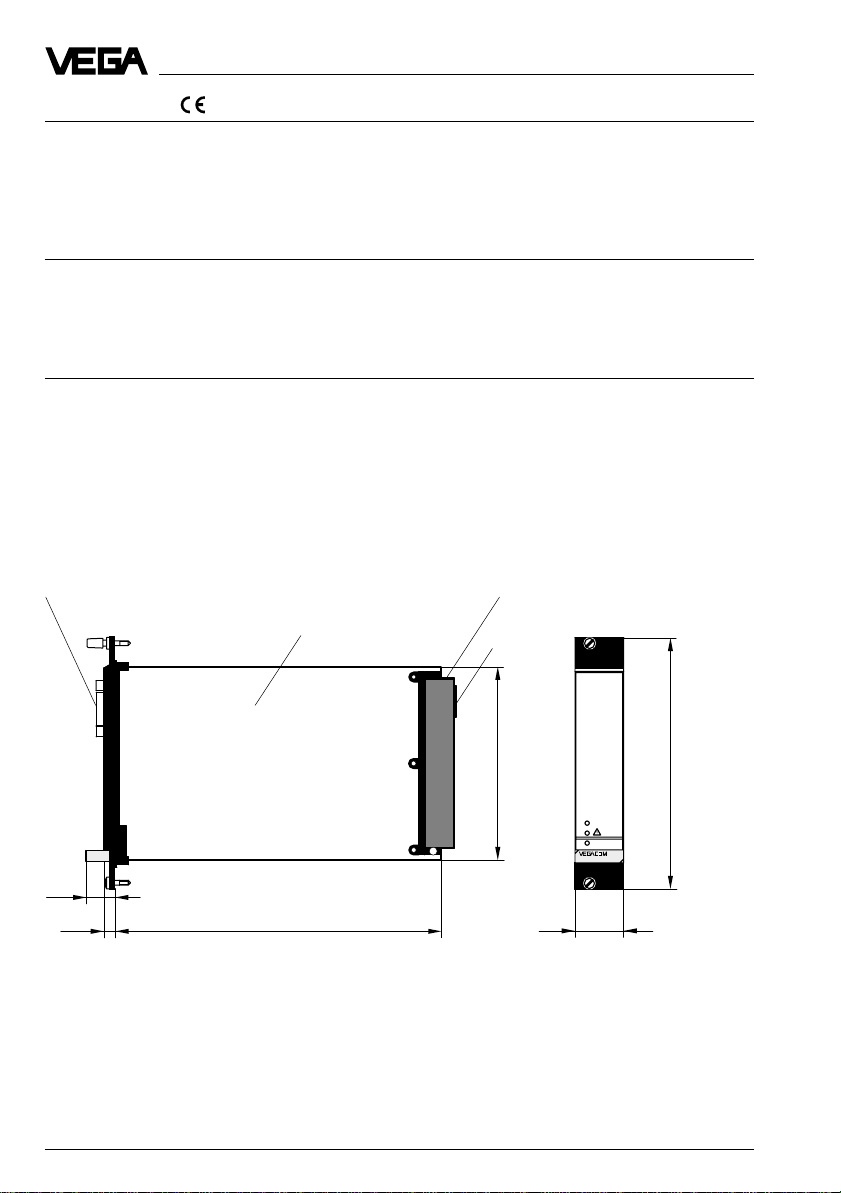
1.6 Dimensions
front RS 232C interface (PC)
Multipoint connector
100 x 160 x 1.5
European size
Multiple plug
LOGBUSplug
100
5 TE
BA
on
128,4
557
15
1625,5
25,4
12 VEGACOM 557 Profibus DP

Product description
1.7 Indicating and adjustment elements
As diagnostic aid, VEGACOM 557 is
equipped with three LEDs. These are located
on the instrument front panel. In addition, the
basic board, as well as the additional board
of VEGACOM 557 are equipped with
switches (DIP switch or hook switch) for
configuration of the available interfaces.
Indicating elements/Diagnostics LEDs
PC
Modbus activity
BA
on
557
Front of VEGACOM 557
Meaning of the LEDs:
VEGA ASCII active:
- green LED lights in case of valid data ex-
change
Fault signal:
- red LED flashing: DISBUS/LOGBUS-error
- irregularly flashing: no PC/DCS outputs
assigned
- permanent light: hardware error or special
function „Freeze Mode“
Voltage supply:
- green LED lights, operating voltage on.
Fault signal
Voltage supply
Adjustment elements
The adjustment elements are located on the
basic board or on the additional board.
A 6-pole DIL switch block on the basic board
is used for adjustment of the fr ont PC interface. The DIL switch and hook switch on the
additional board are used for adjustment of
the Profibus interface.
Basic board
2 3 4ON1
DIL switch
on basic board
Side view of VEGACOM 557
Additional
board
DIL switch
on additional board
Special function “Freeze Mode“
For diagnostic purposes on VEGA processing systems VEGAMET and VEGALOG, the
process image can be “frozen“ in VEGACOM
557 with the adjustment software VVO. This
enables the possibility of carrying out maintenance work on the VEGA system, without
disturbing the higher -priority pr ocessing
system.
For activating the Freeze Modes, a PC must
be connected directly to the PC interface of
VEGACOM 557 and the Freeze Mode must
be switched on under VVO in the menu „Configuration - Measuring system “.
Attention:
Before activating this function, it must be
ensured that during this mode, no disastrous
consequences are to be expected for production processes (during this mode, no
level values etc. are updated).
VEGACOM 557 Profibus DP 13

2 Mounting and electrical
connection
Mounting and electrical connection
2.1 Mounting instructions
The gateway VEGACOM 557 can process
measured data and status information in two
different ways:
- via DISBUS (from measuring systems with
VEGAMET)
- via LOGBUS (from measuring systems
with VEGALOG).
For DISBUS configurations, VEGACOM 557
can be either mounted into carrier BGT 596
or housing type 505.
In conjunction with LOGBUS, VEGACOM 557
in is mounted into carrier BGT LOG 571. The
location is individually selectable, the system
adapts automatically when rebooting
(autoconfiguation).
Coding
A mechanical coding system prevents mixing
up the different module cards in the carrier or
in the housing.
The coding system consists of:
- three coded pins in the multipoint connector
- three holes in the multiple plug of VEGACOM 557.
Instrument Function
coding coding
VEGACOM 557 a27 c3/c11
Instrument coding
d b z
a c
1
3
5
7
9
11
13
15
17
19
21
23
VEGACOM 557
Positioning of the coded pins
a27
25
27
29
31
Function coding
c3
VEGALOG card
c11
Interface card
The coded pins are attached to the module
or the housing. The plug-in socket must be
equipped by the user with the coded pins
according to the following table and diagram.
Coded pin
Plug-in socket of VEGACOM 557
14 VEGACOM 557 Profibus DP

Mounting and electrical connection
2.2 Mounting in carrier and housing
BGT 596 or BGT LOG 571
For mounting, a slot module must be provided at the location. A slot module consists
of:
- a multipoint connector acc. to DIN 41 612,
series F, 33-pole (d, b, z)
- two screws
- three coded pins
- two guide rails.
The multipoint connector is available in the
following versions:
- Wire-Wrap, standard connection
1.0 mm x 1.0 mm
- plug connection
2.8 mm x 0.8 mm
- Termi-Point standard connection
1.6 mm x 0.8 mm
- soldering connection
- screw terminals 0.5 mm
For mounting the module, please note the
operating instructions of the carrier .
Housing type 505, type 506
This housing is already equipped with a
multipoint connector. Before mounting, please
check if the housing is equipped with a
power supply unit or not.
The connection is made via screw terminals
with max. 1.5 mm
in the operating instructions “Housing type
505, type 506 “.
2
2
.
. Further details are stated
2.3 Wiring plan VEGACOM 557
PC interface in front panel (SUB-Dplug)
The PC interface of VEGACOM 557 is used
exclusively for connection of computer systems with VEGA adjustment software via a
COM-Port. The PC interface is based on the
RS 232C standard and is assigned as follows.
1
6
2
7
3
8
4
9
5
Pin assignments of the PC interface of VEGACOM 557
Pin Description I/O
2 RxD receive data I
3 TxD transmit data O
5 GND ground –
Note:
With a direct connection to the computer
system, VEGACOM 557 works without hardware handshake.
Direct connection
For direct connection of a PC to the PC inter face of VEGACOM 557, the interlink (or a
standard) cable available from VEGA with 9pole plugs on both ends should be used.
The pin assignments of the interlink cable are
shown in the diagram.
RxD
TxD
GND
1
6
2
7
3
8
4
9
5
Wiring proposal for interlink cable
1
2
3
4
5
VEGACOM 557 Profibus DP 15
6
7
8
9

Mounting and electrical connection
Connection via modem
For remote parameter adjustment, it is possible to connect the PC interface via a modem.
In such a case, the modem cable that comes
with the respective modem should be used.
Modem operation is supported by VEGACOM 557 from software version 2.11. Further
information on the remote parameter adjustment is stated in the operating instructions
„Remote parameter adjustment “.
Connections of the multiple plug (rear)
For connection of VEGACOM 557 to the existing Profibus DP system, a RS 485 interface
is available. The following diagram shows the
connections of the RS 485 interface, the
power supply of the instrument and the connection to the VEGA system.
dbz
Supply voltage
DISBUS (not
used on VEGALOG)
Multiple plug (rear of VEGACOM 557)
+
2
-
4
6
8
10
12
14
16
18
20
+
22
-
24
26
28
30
32
Profibus DP via RS 485
GND (
DGND
+5V (VP)
DATA (
/DATA (
)
RxD/TxD-P
RxD/TxD-N
)
)
2.4 Mounting and installation instructions with VEGACOM 557AP
As an option, VEGACOM 557 can be extended with the adapter print VEGACOM
557AP. The adapter print VEGACOM 557AP
consists of a module card with 5 TE width
and two modules connected to a back-panel
print for carrier BGT 596 or BGT LOG 571.
BA
on
557AP
557
With the adapter print card it is possible to
put the Profibus DP interfaces of VEGACOM
557 at the front of the carrier . On the fr ont of
the adapter print car d, the Pr ofibus DP interface is available as a 9-pole SUB-D-plug and
as 9-pole SUB-D-socket. The r equired interface type must be stated when ordering
VEGACOM 557AP.
The following interface types are available:
- RS 485 (Profibus DP)
Keep in mind that for Profibus, the interface
type RS 485 is necessary!
The pin assignments of the SUB-D-plug and
the SUB-D-socket are stated in the schedules.
16 VEGACOM 557 Profibus DP

Mounting and electrical connection
Pin assignments VEGACOM 557AP
Pin-Nr.
1
2
3
4
5
6
7
8
9
9-pole SUB-D-plug
Pin-Nr.
1
2
3
4
5
6
7
8
9
9-pole SUB-D-socket
RS 485
-
-
DATA (RxD/TxD-P)
-
GND (DGND)
+5V (VP)
-
/DATA (RxD/TxD-N)
-
RS 485
-
-
DATA (RxD/TxD-P)
-
GND (DGND)
+5V (VP)
-
/DATA (RxD/TxD-N)
-
Mounting instructions for VEGACOM
557AP
The two modules connected to the backpanel print consist of:
- two multipoint connector acc. to DIN 41
612, series F, 48-pole (d, b, z) connected
via the back-panel print
- four screws
- four coded pins
- four guide rails
Module position
BGT LOG 571
The module position is individually selectable,
the VEGALOG 571 processing system
adapts automatically through
autoconfiguration during the first booting.
After autoconfiguration, the slot location of the
cards must never be changed.
BGT 596
The module position is individually selectable.
Please note that the two connected modules
cover a width of 10 TE (5 TE for VEGACOM
557 plus 5 TE for the adapter board
VEGACOM 557AP).
Connection VEGACOM 557AP
BGT LOG 571
With the bus board (part of the carrier BGT
LOG 571) connection to LOGBUS is made
automatically when inserting VEGACOM 557.
The voltage supply of the card must be provided separately. For this r eason, a 2-pole
terminal with tension spring connection,
called U
print. The permissible operating voltage of
VEGACOM 557 should be observed. In case
of DC voltage supply , the corr ect polarity
should be noted!
is available on the back-panel
b,
Coding
The coding should be carried out for both
modules as described in chapter “2.1 Mounting in carrier and housing “. The coded pin c3
BGT 596
When operating VEGACOM 557 as
DISBUS participant, the DISBUS must be
wired in addition to the supply voltage.
will not be inserted.
For the two cables of the DISBUS, a 2-pole
terminal with tension spring connection is
available. Make sur e that the polarity is cor rect!
VEGACOM 557 Profibus DP 17

Terminals
for supply voltage
Terminals
for DISBUS
Ub+
View of back-panel board (rear of the carrier)
Modbus interface
PC interface of
VEGACOM 557
of VEGACOM 557
as SUB-D-plug
Mounting and electrical connection
PC
BA
on
557
Modbus interface
of VEGACOM 557
as SUB-D-socket
557AP
Front view with SUB-D-connections of VEGACOM 557
and VEGACOM 557AP
18 VEGACOM 557 Profibus DP

Switch adjustments on VEGACOM 557
3 Switch settings on VEGACOM
557
For adjustment of the interfaces or the BUS
parameters of the PC interface and the Modbus interfaces, various DIL switches are
provided on VEGACOM 557. Before inserting
VEGACOM 557 into the carrier or the housing, the DIL switches must be set according
to the user-specific data. The data of these
settings will be effective with the next initialization (switching on of voltage).
3.1 Adjustment of the PC interface
For adjustment of the RS 232 PC interface in
the front panel of VEGACOM 557, a 6-pole
DIL switch block is located on the basic
board. The PC interface is used for communication between a PC and VEGACOM 557, by
means of the adjustment software VVO or the
visualisation software VV.
Instrument number
Only relevant when operating two
VEGACOM 557 on the same DISBUS. If
two VEGACOM 557 are operated on the
DISBUS, then different instrument numbers
have to be assigned.
Not relevant for operation on LOGBUS.
Automatic modem initialization
In position „ON“ the modem will be initialized automatically when connecting it to the
VEGACOM interface.
Transmission rate
For VVO or VV , the transmission rate must
be set to 9600 baud.
In the following diagram, you see all possible
adjustment possibilities for configuration of
the PC interface.
ON
Basic board
2 3 4ON1
DIL switch
on basic board
Side view of VEGACOM 557
Additional
board
DIL switch
below additional
board
The following adjustments are carried out via
the above mentioned DIL switch block.
Data format
Parity can be switched from even to no
parity (note for VVO including version 2.15,
even parity is compulsory).
123 4 5 6
Data format
8 data bits, 1 stop bit, even parity
8 data bits, 1 stop bit, no parity
Instrument number
1. instrument
2. instrument
Automatic modem initialization
On
Off
Transmission rate (baud)
300
600
1200
2400
Adjustment possibilities of the DIL switch on the
basic board
4800
9600
19200
38400
VEGACOM 557 Profibus DP 19

Switch adjustments on VEGACOM 557
3.2 Adjustment of the Profibus DP interface
A 8-pole DIL switch block as well as two hook
switches for configuration of the Profibus DP
interface to the DCS or the PLC are located
on the additional board.
DIL switch blocks
additional board
1 2 3
Basic board
Front
plate
Additional
board
DIL switch
basic board
Bottom view of VEGACOM 557
1 2 3 4 5 6 7 8
L RL R
12
Hook switches
additional
board
2 1
Multiple plug
DIL switch additional board
The DIL switch is used to select the slave
address of VEGACOM 557 on the Profibus
DP.
DIL-switch block
(Additional board)
ON
12345678
Factory setting:
Slave address = 12
DIL switch block on the additional board for selecting
the Slave address
Profibus Slave address of VEGACOM 557
SW 8 SW 7 SW 6 SW 5 SW 4 SW 3 SW 2 SW 1
off 2625242322212
SW 8 is reserved and must be set to position
“off“. Permitted address range 0 … 126.
Example:
Address 32 corresponds:
SW 8 SW 7 SW 6 SW 5 SW 4 SW 3 SW 2 SW 1
off off on off off off off off
0
Bottom view of the additional board
ON
12345678
Slave address = 32
20 VEGACOM 557 Profibus DP

Switch adjustments on VEGACOM 557
Hook switches additional board
The hook switches are used to switch on the
bus terminator resistors.
Switch positions
Hook switch closed:
Bus terminator "On"
1
2
Hook switch open:
1
Example 1:
VEGACOM 557 PLC
Both hook switches are
closed
If a VEGACOM 557 is connected to a PLC,
both hook switches have to be closed (bus
terminator ON).
Bus terminator "Off"
2
Example 2:
VEGACOM 557
Both hook switches Both hook switches
closed open open closed
PLC
VEGACOM 557
If several VEGACOM 557 are connected to a
PLC, both hook switches have to be closed
on VEGACOMs located at the beginning and
end of the connecting line, and open on
VEGACOM 557s located in between.
VEGACOM 557 Profibus DP 21

Measurement loop in VEGAMET/VEGALOG
4 Measurement loop in VEGAMET/VEGALOG
Generally a measurement loop in VEGAMET/VEGALOG processing systems is structured as
follows:
A sensor delivers the sensor value to the input of the processing system. This sensor value is
then further processing in the processed system (.e.g. empty/full adjustment, linearisation ...).
The processed values are outputted (e.g. via current outputs, relay outputs ...). The PC/DCS
output is available as gateway for VEGACOM 557, i.e. the processing system transmits the
PC/DCS output value via the DISBUS or LOGBUS to VEGACOM 557. This values are accessible to the PC/DCS system via the field bus.
Sensors
VBUS, 4...20mA
Sensor value
VEGALOG/
VEGAMET input
VEGALOG / VEGAMET
(Resolution= 0...10000)
(Resolution= 0...1000)
Empty/
adjustment
Linear-
full
isation
Unit: 0,00%
Unit: 0,0%
Unit: 0,00%
Unit: 0,0%
Scaling
DISBUSLOGBUS
VEGALOG/VEGAMET
PC/DCS output
Parameter
selection
DISBUS
or
LOGBUS
LOGBUS/
DISBUS
Fieldbus
PC/DCS value
Fieldbus PC/DCS
PC/DCS systemVEGACOM 557
system
Parameter: Percent
mA
bar
m
Volume
percent
Scaled
selected
parameter+
unit
Fundamental configuration of a measurement loop
22 VEGACOM 557 Profibus DP

Measurement loop in VEGAMET/VEGALOG
4.1 PC/DCS output
Max. 255 PC/DCS outputs are available,
depending on the processing system. The
configuration or parameter setting of the PC/
DCS outputs is done with the adjustment
software VVO or via keyboard (VEGAMET) in
the processing system. Several PC/DCS
outputs can be allocated to each measurement loop. This enables the possibility of
transmitting the measured value, e.g. as
“Percentage value“ and “Scaled“, e.g. in
“Liters“ to the Pr ofibus master.
Processing system No. of PC/DCS outputs
VEGAMET 509 3
VEGAMET 512 3
VEGAMET 513 3
VEGAMET 514(V) 3 ( 7)
VEGAMET 515(V) 7(7)
VEGAMET 614(V) 3(7)
VEGALOG 571 max. 255
Automatic allocation of a PC/DCS output
It is possible to allocated another or further
PC/DCS outputs to a measurement loop later
on.
Via the menu items „
ment loop, Modify
outputs
“, you reach the window “PC/DCS
Configuration, Measure-
“ and the button “
PC/DCS
coordination“.
Existing PC/DCS outputs
Configuration of the PC/DCS output via
VVO
A PC/DCS output is automatically allocated to
each measurement loop created in the
processing system. As a standard feature,
the PC/DCS output number is assigned automatically. The next fr ee PC/DCS output
number is always used. If, e.g. the PC/DCS
outputs 3, 4, 5 and 6 are still free, the PC/
DCS output number 3 is automatically allocated to the new measurement loop. Which
output number will be allocated, is shown in
VVO during creation of a new measurement
loop in the window „Create new measurement
loop - Measurement loop designation “. By
pushing the button „
PC/DCS address
“, a
new window opens in which the allocation of
the output number can be carried out manually.
VEGACOM 557 Profibus DP 23
PC/DCS output coordination
Parameter settings of the PC/DCS output via VVO
The following parameter settings can be
made for the PC/DCS output:
- parameters to be transferred, e.g. percent
- unit in which the parameter should be
transferred, e.g. 0.00 %
- transfer error code in the PC/DCS value
(from VVO 2.60)
- measured value limitation

Measurement loop in VEGAMET/VEGALOG
Examples of parameter settings: parameter, unit
Percent is chosen as parameter and 0.0% as
unit. The measured value 0.0 … 100.0 % is
transferred with these parameters as PC/
DCS value 0 … 1000.
Percent is chosen as parameter and 0.00%
as unit. The measured value
0.00 … 100.00 % is transferred with these
parameters as PC/DCS value 0 … 10000.
Note
The PC/DCS value is always transferred
without decimal point!
The adjustment of the parameter and the unit
can be made separately for each PC/DCS
output and has no influence on the other
outputs of the measurement loop. The parameter settings are done in the window
„PC/DCS“. This window is reached under
VVO via the menu items „
Parameter adjustment,
measurement loop, „
measured value
,“ button „
measured value and PC/DCS
Instrument data,
“ choose requested
Outputs, Display of
Outputs, Display of
“.
In the window „PC/DCS“, „scaled“ must be
chosen as parameter after the scaling.
Note
The scaling is used by each output of the
measurement loop that applies the parameter
„scaled“. Modifications in the scaling will then
affect all connected indicating instruments!
Transfer error code in the PC/DCS value
From VVO version 2.60, it is possible to
transfer an error code if there is interference
in a measurement loop. The error code is
then transferred in the PC/DCS value instead
of the measur ed value. To have the err or
code transferr ed in this way , “Transfer failure
messages to PC/DCS “ must be activated in
the window “PC/DCS“.
Adjust limitation of measured values
Further optional parameter settings can be
found in the window „Limitation of measured
values“.
In this window, it is possible to suppr ess
negative measured values, i.e. measured
values <0% are limited to 0%.
As another option, measured values <-10 %
and >110 % can be outputted as a fault signal.
Note
These options influence all outputs of the
measurement loop!
Parameter setting PC/DCS outputs
Scaled is selected as parameter . The measured value 0 … 100 % shall be transferred to
the PC/DCS system as PC/DCS value
10 … 5000. First of all, a scaling must be
The window can be reached via the following
menu items: „
adjustment,
loop, button „
measured values
Instrument data, Parameter
“ select requested measurement
Conditioning and Limitation of
“.
carried out for the measurement loop. Via the
menu items „
adjustment,
ment loop, button „
Parameter setting of the scaling
Instrument data, Parameter
“ choose the requested measure-
Conditioning and scaling
“.
Limitation of measured values
24 VEGACOM 557 Profibus DP

Transfer of measur ed value
5 Transfer of measured value
As DP norm slave, the VEGACOM 557 DP
gateway is either configured with 50 Byte
consistent input data and 2 Byte consistent
output data or with 6 Byte consistent input
data and 6 Byte consistent output data (see
chapter „6 Operating mode VEGACOM
557“)
.
The DP master transmits via the inputs
control information to VEGACOM 557, to
which VEGACOM 557 r esponds accor dingly,
making the data available to the DP master
as input information.
5.1 Format for transfer of measured
value
Measured values and PC/DCS values
The measured values of the VEGA processing systems (VEGAMET or VEGALOG) connected to VEGACOM 557 are reproduced on
the input bytes of the Profibus master as
described in chapter 4. They are available in
VEGACOM 557 as so-called PC/DCS values.
A PC/DCS value consists of 6 Byte.
Structure of a measured value
Measured values of VEGALOG or VEGAMET
processing system are transferred to VEGACOM 557 as 2 Byte signed data. This means
that the value range comprises max.
+32.768 up to -32.767.
Structure of a PC/DCS value
An individual PC/DCS value in VEGACOM
557 consists of 6 Byte and is structured as
follows:
PC/DCS value
Measured value
Additional info. High word Low word
Byte 1 Byte 2 Byte 3 Byte 4 Byte 5 Byte 6
Index Status
high
low high low
The real measured value is in the low word of
the measured value and with a length of 2
Byte and signed, this means that the value
range is +32768 up to -32767.
The 2 Byte of the high word of the measured
value are not used at present - they are filled
with the value zero.
In addition to the measured value, VEGACOM 557 provides per DCS value one Byte
for the PC/DCS index and another Byte for
information on the current measured value
status.
The PC/DCS output number is transferred in
the byte index. The status describes the
conditions of the respective measured value.
The contents of the measured value is only
valid if the respective status has the value
zero.
If the status value is not equal to zero, the
status value and the respective value in the
measured value field must be taken into
account for a detailed error diagnosis. The
following list explains the possible errors:
Status M eas. valueMeaning
0x00 0xXXXX valid measured value
0x01 0xXXXX simulated meas. value
(only on VEGAMET 509
and 512)
0x80 0xXXXX old meas. value (prob-
ably connection separated)
0xFE 0x0000 there is no meas. value
available (not configured)
0xFF 0xFFFF there is no VEGAMET or
VEGALOG connected
0xFF 0x00XX failure message of an
individual meas. loop
XX = error type
0xFF 0x8000 failure message of an
individual meas. loop
Error type not defined
VEGACOM 557 Profibus DP 25

6 Operating mode VEGACOM 557
Operating mode VEGACOM 557
Two dif ferent operating modes ar e available
for VEGACOM 557.
Depending on the operating mode, VEGACOM 557 reserves a different number of
input and output bytes in the Profibus-Master.
6.1 Mode 50E2A
In this mode, VEGACOM 557 reserves 50
input bytes and 2 output bytes.
The Profibus-Master has to process 50 Bytes
of data consistently .
How it works
A control command and a block number (1
byte each) are written into the 2 Byte output
data. After VEGACOM 557 has received
these two Bytes via Pr ofibus DP, it answers
by sending the data of the required block these 50 Byte are then available to the Profibus-Master as input bytes.
Since a maximum of 255 PC/DCS values and
up to 32 relay status are available in VEGACOM, but only 50 bytes at a time can be
transferred on the Profibus, the data are
multiplexed on the bus.
To facilitate this, the data ar e divided in
VEGACOM 557 into blocks. The requested
block can be enquired by the Profibus-Master with the control command and the block
number.
8 PC/DCS values (6 Byte each), the control
command (1 Byte) and the block number (1
Byte) decremented by the value 1 are returned in a block.
6.2 Mode 6E6A
In this mode, VEGACOM 557 reserves 6
input byte and 6 output byte.
The Profibus-Master must process 6 Byte
data consistently.
How it works
A control command and a PC/DCS value
number (1 Byte each) is written by the Profibus-Master into the 6 Byte output data, the
remaining 4 Byte must be filled with the value
0xFF.
After VEGACOM 557 has received these 6
Byte via the Pr ofibus DP, it answers by sending the data of the enquired PC/DCS value.
These 6 Byte are then available as input
bytes to the Pr ofibus-Master.
Since a maximum of 255 PC/DCS values and
up to 32 relay status are available in VEGACOM, but only 6 bytes at a time can be
transferred on the Profibus, the data on the
bus are multiplexed.
To facilitate this, the data in VEGACOM 557
are divided into single PC/DCS values. With
the control command and the PC/DCS value
number, the Pr ofibus-Master can enquir e t he
respective PC/DCS value.
6.3 Selection of the operating mode
To select the operating mode, it is necessar y,
to choose the respective configuration when
creating the bus configuration. The GSD file
provides both operating modes as options.
The selection is made with the respective
configuration tool, e.g. HW-Config for SIEMENS S7 systems or COM PROFIBUS for
SIEMENS S5 systems.
Depending on the configuration tool, a window is opened in which the desired operating mode can be selected when adding a
VEGACOM 557 slave to the bus configuration.
26 VEGACOM 557 Profibus DP
 Loading...