

Page 1
Operating instructions
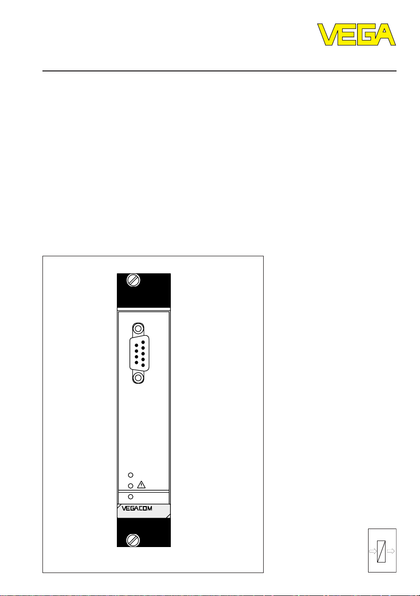
VEGACOM 557
VEGA ASCII protocol
Level and Pressure
BA
on
PC
557
out
in
Page 2

Contents
Safety information ..................................................................................................... 2
Note Ex area ............................................................................................................. 2
1 Product description
1.1 Application ......................................................................................................... 4
1.2 Configuration ..................................................................................................... 4
1.3 Functions ........................................................................................................... 5
1.4 Type plate .......................................................................................................... 9
1.5 Technical data .................................................................................................. 10
1.6 Dimensions ...................................................................................................... 12
1.7 Indicating and adjustment elements ............................................................. 13
2 Mounting and electrical connection
2.1 Mounting instructions ...................................................................................... 14
2.2 Mounting in carrier and housing .................................................................... 15
2.3 Wiring plan VEGACOM 557 ........................................................................... 15
2.4 Mounting and installation instructions with VEGACOM 557AP ................... 17
Contents
Safety information
Please read this manual carefully, and also take
note of country-specific installation standards
(e.g. the VDE regulations in Germany) as well
as all prevailing safety regulations and accident prevention rules.
For safety and warranty reasons, any internal
work on the instruments, apart from that involved in normal installation and electrical connection, must be carried out only by qualified
VEGA personnel.
2 VEGACOM 557 VEGA ASCII
Note Ex area
Please note the approval documents (yellow
binder), and especially the included safety
data sheet.
Page 3

Contents
3 Switch settings on VEGACOM 557
3.1 Adjustment of the PC interface ...................................................................... 20
3.2 Adjustment of the VEGA ASCII interface ...................................................... 21
4 Data image in VEGACOM 557
4.1 Enquiry for VEGAMET with three or less values per instrument ................ 26
4.2 Enquiry for VEGAMET with up to seven values per instrument ................. 28
4.3 Enquiry as block with low resolution ............................................................. 30
4.4 Enquiry as single value with low resolution ..................................................32
4.5 Enquiry as range with low resolution ............................................................ 34
4.6 Enquiry as block with address and low resolution ......................................36
4.7 Enquiry as single value with address and low resolution ........................... 38
4.8 Enquiry as range with address and low resolution ..................................... 40
4.9 Enquiry for the contact inputs and outputs on DISBUS .............................. 42
4.10 Enquiry for the contact inputs and outputs on LOGBUS ............................ 43
4.11 Enquiry for the software version .................................................................... 44
4.12 Error information from VEGACOM 557 .........................................................44
4.13 Parameter adjustment of VEGALOG or VEGAMET via VEGA ASCII ......... 45
5 Setup
5.1 Setup check list: ...............................................................................................46
5.2 Communication structure ................................................................................. 46
5.3 Setup example for the PC ............................................................................... 47
5.4 Example program for the enquiry VEGAMET (QUICK BASIC) .................. 49
5.5 Example program for the enquiry VEGALOG (VISUAL BASIC 4.0) ........... 53
Supplement A ..............................................................................................................56
VEGACOM 557 VEGA ASCII 3
Page 4
1 Product description
Product description
1.1 Application
The VEGACOM 557 is an efficient and easyto-use interface converter (Gateway) for your
measurement applications. It is used for
conversion of the VEGA-specific protocols of
DISBUS and LOGBUS into standard data
formats.
The existing version is used for connection of
level or pressure measuring systems to
Profibus DP systems such as
- processing systems (DCS)
- personal computers (PC)
- stored program control (PLC).
In addition, it is used for connecting a PC for
configuration or visualisation via the VEGA
adjustment software.
If connection is made to external systems,
there is the possibility of calling up measurement data and status information of the measuring systems via the master of the external
system. The coupling of the external system
is made via the connections on the rear of the
instrument. This data traffic requires that
special measures (described in this manual)
be taken in setting up the master of the external system. The data received in the master
can be visualised there or further processed
for control purposes. In restricted volume,
signal conditioning instrument-specific parameters can be outputted, modified and
returned again.
Via the PC interface on the front of VEGACOM 557, the VEGA visualisation software
"Visual VEGA“ or the VEGA configuration
software "VEGA Visual Operating“ (VVO) can
be operated. For these applications, the
coupling between VEGACOM 557 and a PC
is made directly with the connection cable
between the RS 232 interface (PC) on the
front of VEGACOM 557 and a standard Port
(e.g. COM1) of your PC. There is also the
possibility to provide a connection via modems.
1.2 Configuration
The component VEGACOM 557 is designed
in 19" technology with 5 TE width (1 TE = 5.08
mm) acc. to DIN 41 494. It can be used:
- in carrier BGT 596
- in VEGALOG 571 carrier BGT LOG 571
- in housing type 505.
The electrical connection of supply voltage,
DISBUS and Modbus is made via a plug
connection acc. to DIN 41 612 on the rear of
the component. The connection to LOGBUS
is made via an additional 5-pole plug-connector mounted to the DIN-socket.
A 9-pole SUB-D plug marked “PC” is located
on the front panel of VEGACOM 557. It is
used for connection of a PC via RS 232C to
VEGACOM 557.
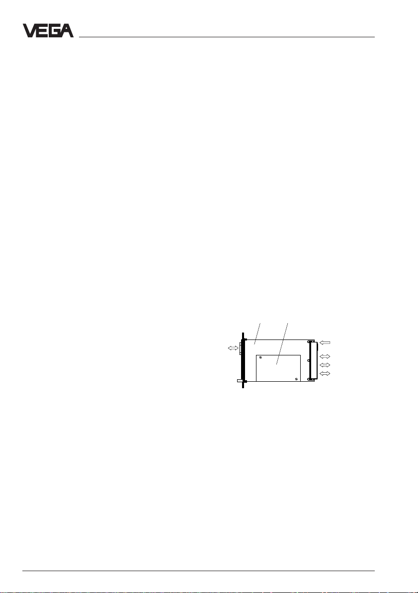
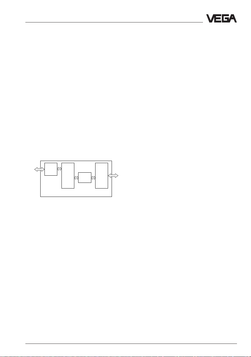
Basic board
PC
interface
VEGACOM 557 connections
The component consists of two boards:
- the basic board
- the additional board.
On the basic board, you will find the power
supply unit, the PC interface, the DISBUS/
LOGBUS interface as well as the connections
for the VEGA ASCII interface.
The additional board is screwed to the basic
board and includes the hardware of the
VEGA ASCII interface as well as the protocol
specific programs.
Additional board
Supply
DISBUS
LOGBUS
Modbus
4 VEGACOM 557 VEGA ASCII
Page 5
Product description
1.3 Functions
The VEGACOM 557 interface converter can
be integrated into the VEGA level or pressure measuring system in two different ways:
either
- as DISBUS participant
or
- as LOGBUS participant.
In both cases, VEGACOM 557 operates as
passive participant and provides measured
data and status information of the connected
VEGA signal conditioning instruments via the
external system. Through the use of readable text, a connection with simple terminal
programs is possible.
Alternatively, it is possible to connect a PC
with VEGA adjustment software via the SUBD-plug marked “PC” on the front panel of
VEGACOM 557. VEGA adjustment software
is actually available as two different Windows
applications.
VVO = VEGA Visual Operating
For configuration and parameter adjustment of the connected VEGAMET or VEGALOG processing systems
VV = Visual VEGA
For visualising and recording of measured
values of complete (multiple) vessel installations.
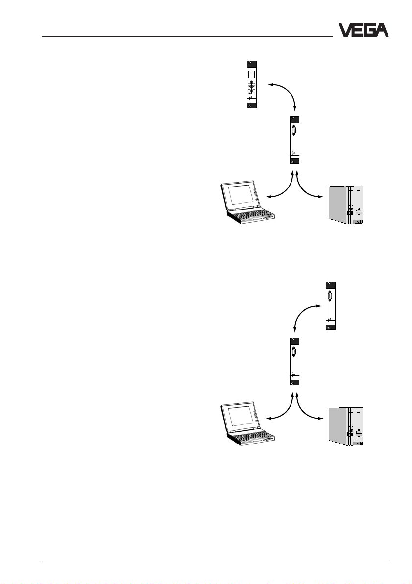
The following pictures show the basic connection possibilities of VEGACOM 557.
VEGAMET
DISBUS
%
100
+
-
ESC OK
CONNECT
!
on
VEGAMET
513
VEGACOM 557
PC
BA
!
on
VEGACOM
557
VVO
VEGA adjustment software
PC connection
VEGA ASCII
External
Master
VEGACOM 557 as DISBUS participants
VEGALOG 571
LOGBUS
PC
VEGACOM 557
BA
!
on
VEGACOM
557
PC
!
on
VEGALOG
571
VVO
VEGA adjustment software
PC connection
VEGA ASCII
External
Master
VEGACOM 557 as LOGBUS participant
VEGACOM 557 VEGA ASCII 5
Page 6
Product description
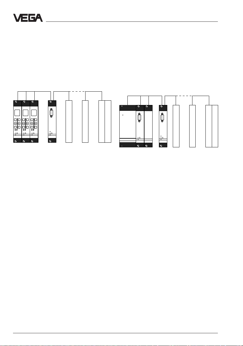
VEGACOM 557 on DISBUS
VEGAMET series 500/600 signal conditioning
instruments transmit via the DISBUS cyclically measured data and status information,
so called PC/DCS telegrams. VEGACOM 557
receives these data as participant on the
DISBUS and makes them available (in buffer
memory) for collection via the VEGA ASCII
protocol.
DISBUS
-
ESC OK
VEGAMET
100
CONNECT
!
on
+
+
+
-
-
ESC OK
ESC OK
CONNECT
CONNECT
!
!
on
on
VEGAMET
VEGAMET
513
513
513
%
%
%
100
100
VEGAMET
Connection VEGACOM 557 to DISBUS
VEGA ASCII
PC
BA
!
on
VEGACOM
557
VEGACOM
further
VEGACOM
External
Master
If a PC is connected to the PC interface (front
interface) of VEGACOM 557, this instrument
transfers acyclically (on request by the
VEGA configuration software VVO) measurement loop parameters from or to VEGAMET.
Max. two VEGACOM 557 can be connected
to the same DISBUS. For clear identification,
a different instrument address should be
assigned to each instrument.
VEGACOM 557 on LOGBUS
Data are exchanged continuously on the
LOGBUS between the individual components
of VEGALOG 571. VEGACOM 557 receives
as participant of this LOGBUS PC/DCS telegrams including the measured values and
status information and makes them available
(in buffer memory) for collection via the VEGA
ASCII protocol.
LOGBUS
on
PC
!
on
VEGALOG
571
VEGALOG
Connection VEGACOM 557 to LOGBUS
VEGA ASCII
PC
BA
!
on
VEGACOM
557
VEGACOM
further
VEGACOM
External
Master
If a PC is connected to the PC interface (front
interface) of VEGACOM 557, this instrument
transfers acyclically (on request by the
VEGA configuration software VVO) measurement loop parameters from or to VEGALOG
571.
Max. two VEGACOM 557 can be connected
to the same LOGBUS. The addressing for
clear identification is made automatically on
LOGBUS.
6 VEGACOM 557 VEGA ASCII
Page 7
Product description
VEGACOM 557 with VEGA ASCII
The data communication between VEGACOM
557 and a master is only carried out if initiated by the master, which can enquire the
requested information by means of special
commands.
The data from DISBUS/LOGBUS are first
written in a buffer memory of VEGACOM 557.
The data set is transferred from this buffer
memory into a process image. The protocol
conversion software enquires the stored data
cyclically from the individual storage areas.
The data sets are checked and converted
into the VEGA ASCII data format. After the
conversion, the data are transferred into the
emission memory and are sent from there to
the master.
DISBUS
LOGBUS
Function VEGACOM 557
Buffer
memory
Process
image
Test
conversion
Emission
memory
VEGA
ASCII
VEGACOM 557 with VVO or VV
Direct connection
As an alternative to the VEGA ASCII communication, a PC can be connected via the PC
interface (SUB-D-plug in the front panel of
VEGACOM 557). By means of the adjustment
and indicating software VEGA Visual Operating (VVO), the parameter adjustment can be
made on the signal conditioning instruments
connected to VEGACOM 557. The adjustment concept includes the user-friendly configuration and parameter adjustment of the
measuring system or the sensor with the
following instruments:
- VEGAMET series 500/600 signal conditioning instruments
- VEGALOG 571 processing system
- VBUS ultrasonic/radar sensors.
The adjustment is menu-driven and window
orientated. No matter if a radar sensor, several connected signal conditioning instruments or a VEGALOG should be adjusted via
the PC, the procedure is always the same.
As another possibility, measured values and
fault signals of the entire processing facility
can be recorded and shown graphically by
means of the visualisation software VISUAL
VEGA (VV). Tools for processing and analysis of history data are also available.
The configuration of the measurement loop
comprises, depending on the connected
instruments, e.g. the determination of output
functions or the configuration of individual
outputs or inputs. The user-orientated editing
of measurement loops is supported by
graphic means, such as e.g. vessel drawings and pictographs that adapt to the selected general conditions and options.
Thanks to the graphical support, even more
complex parameter adjustments such as e.g.
the input of a linearisation curve by means of
index markers can be done with ease.
Connection via modem
The PC interface supports, beside the direct
connection of a PC, also the operation via
modems. With this additional function, remote
parameter adjustment or remote diagnostics
of VEGA systems via VVO are possible.
Together with the visualisation software Visual
VEGA, even remote visualisations can be
carried out.
VEGACOM 557 VEGA ASCII 7
Page 8
Product description
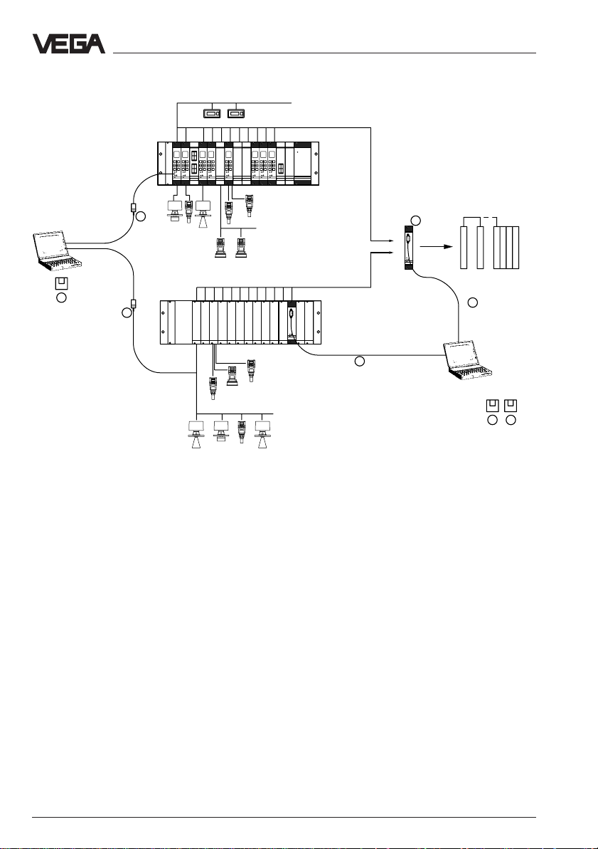
Complete measuring system with digital communication and networking
DISBUS
%
%
%
100
100
+
-
-
ESC OK
ESC OK
CONNECT
!
!
on
on
VEGAMET
VEGAMET
513
%
%
%
100
100
100
+
+
-
-
ESC OK
ESC OK
CONNECT
CONNECT
!
!
on
on
VEGAMET
VEGAMET
513
513
100
+
+
-
-
ESC OK
ESC OK
CONNECT
CONNECT
!
!
on
on
VEGAMET
VEGAMET
513
513
on
%
%
100
100
+
+
+
-
-
ESC OK
ESC OK
CONNECT
CONNECT
CONNECT
!
!
on
on
VEGAMET
VEGAMET
513
513
513
4
O
V
V
LOGBUS
1
4
PC
!
on
VEGALOG
571
Measuring system with digital communication and networking
Explanation:
3 VEGACOM 557
1 VEGA Visual Operating (VVO)
Adjustment software for the PC for the
user-friendly configuration and parameter
adjustment of VEGA instruments
- VEGALOG 571 directly via RS 232
connection cable on the CPU card or
VEGACOM 557
4 VEGACONNECT 2
- several VEGAMET via VEGACOM 557
or individually via VEGACONNECT
- VEGASON, VEGAPULS via VEGACONNECT on the signal line or on the sensor
2 Visual VEGA (VV)
PC visualisation software for presentation
5 RS 232 connection cable (interlink cable)
of measurement data from VEGA instruments in a graphical or tabular form. Integration of individual measurement loops
into groups, saving of fault signals and
measured values (recorder function).
Suitable for networks
3
VEGA
PC
ASCII
BA
!
on
VEGACOM
557
5
V
5
V
2
1
Interface converter for conversion of VEGA
specific protocols into standard data formats. Suitable for connection to the DISBUS output of VEGAMET series 500/600
signal conditioning instruments or the LOGBUS of VEGALOG 571 processing system.
Connection cable (interface converter)
between VEGA instruments (VEGASON,
VEGAPULS or VEGAMET) and a PC in
conjunction with the adjustment software
VEGA Visual Operating.
Connection cable between PC and VEGALOG 571-CPU or VEGACOM 557
External system
8 VEGACOM 557 VEGA ASCII
Page 9
Product description
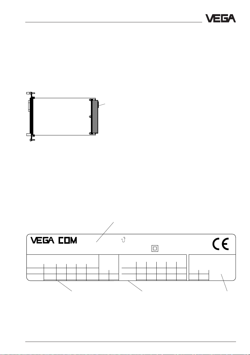
1.4 T ype plate
Type plate
Before mounting and electrical connection,
please check if you are using the correct
version of VEGACOM 557. Please note the
type plate, located below the multiple plug.
Type plate on
multiple plug
The type plate contains important data required for electrical connection. The configuration and the components of the type plate
are explained in the illustration below.
Note:
The serial number of your VEGACOM is on
the rear of the plug connector.
1
®
RS 422 /Rx /Tx GND_1TxRx
RS 485
d32 z32 z30d30
DATA GND_1
557
VEGA ASCII
DIS
-+
d28
z22z24
a: -20 ... +60˚C
IP 40 (front)
TTY
R- T- R+
RS 232
d20 z20 d16d18
Insp.
power supply
z18
GND
GNDRxD
20 ... 53V AC
20 ... 72 V DC
N-L+
6 VA
z2d2
T+
TxD/DATA
33 2
1 Version: VEGA ASCII
2 Supply voltage
3 Terminal assignment of the possible interface to VEGA ASCII
VEGACOM 557 VEGA ASCII 9
Page 10
Product description
1.5 T echnical data
Power supply
Supply voltage U
Power consumption approx. 6 VA
Fuse 1 A, slow-blow
Electrical connection
Component multiple plug acc. to DIN 41 612, series F
Module in carrier
BGT 596 or BGT LOG 571 suitable multipoint connector acc. to DIN 41 612
Housing type 505 via screw terminals max. 1 x 1.5 mm
Indicating elements
LED on front panel green "BA“: VEGA ASCII active
Meas. data input DISBUS
Data transmission DISBUS (digital data transmission)
Connection cable 2-wire standard cable (shielded)
Cable length max. 1000 m
Measuring data input LOGBUS
Data transmission LOGBUS (digital data transmission)
Connection cable connection via BUS-plug
= 24 V AC (20 … 53 V), 50/60 Hz or
nom
= 24 V DC (20 … 72 V)
48 pole (d, b, z) with coding holes
with connection via standard technologies
2
red: failure, freeze mode
green "on“: operating mode
PC interface
Interface standard RS 232C
Cable length max. 15 m
Transmission rate in baud 300, 600, 1200, 2400, 4800,
96009600
9600, 19200, 38400
96009600
Transmission format 8 data bits, 1 stop bit, no parity or even
parity
Plug on front panel SUB-D-plug connector, 9 pole, pins
Modbus interfaces
Interfaces RS 232 RS 422 RS 485 TTY
Cable length 15 m 1200 m 1200 m 1000 m
Connection cable 3-wire 5-wire 3-wire 4-wire
twisted in pairs, shielded
Transmission mode serially asynchronous, half-duplex
Transmission rate 300; 600; 1200; 2400; 4800; 9600; 19200;
38400 baud
Galvanic separation up to 0.5 kV
10 VEGACOM 557 VEGA ASCII
Page 11
Product description
Modbus ASCII-mode
Coding system hexadecimal, ASCII-character
Number of bits 1 start bit, 7 or 8 data bits, 1 (0) parity bit,
Parity NONE, ODD, EVEN
Backup none
Electrical protective measures
Protection:
not mounted IP 00
in carrier BGT 596
or BGT LOG 571
- front side completely equipped IP 40
- upper and lower side
BGT 596 IP 00
BGT LOG 571 IP 20
- wiring side IP 00
in housing type 505
- front side IP 40
- other sides IP 30
Protection class II (in housing type 505)
Overvoltage category II
Electrical separation measures
Reliable separation acc. to VDE 0106, part 1 between power supply, LOGBUS, DISBUS,
PC-connection and respective interface
- reference voltage 250 V
- test voltage 2 kV
1 stop bit
Ambient conditions
Permissible ambient temperature -20°C … +60°C
Storage and transport temperature -20°C … +85°C
Humidity 93 %, T = 40°C acc. to DIN/IEC 68-2-3
Shock 2 … 100 Hz, 0.7 g
Mechanical data
Series module unit for
Dimensions, not mounted W = 25.4 mm (5 TE), H = 128.4 mm, D = 166 mm
Weight approx. 550 g
CE conformity
VEGACOM 557 meets the protective regulations of EMC (89/336/EWG) and NSR
(73/23/EWG). The conformity has been judged acc. to the following standards:
EMC Emission EN 50 081 - 2: 1993
Susceptibility EN 50 082 - 2: 1995
NSR EN 61 010 - 1: 1993
VEGACOM 557 VEGA ASCII 11
- carrier BGT 596
- carrier BGT LOG 571
- housing type 505
Page 12
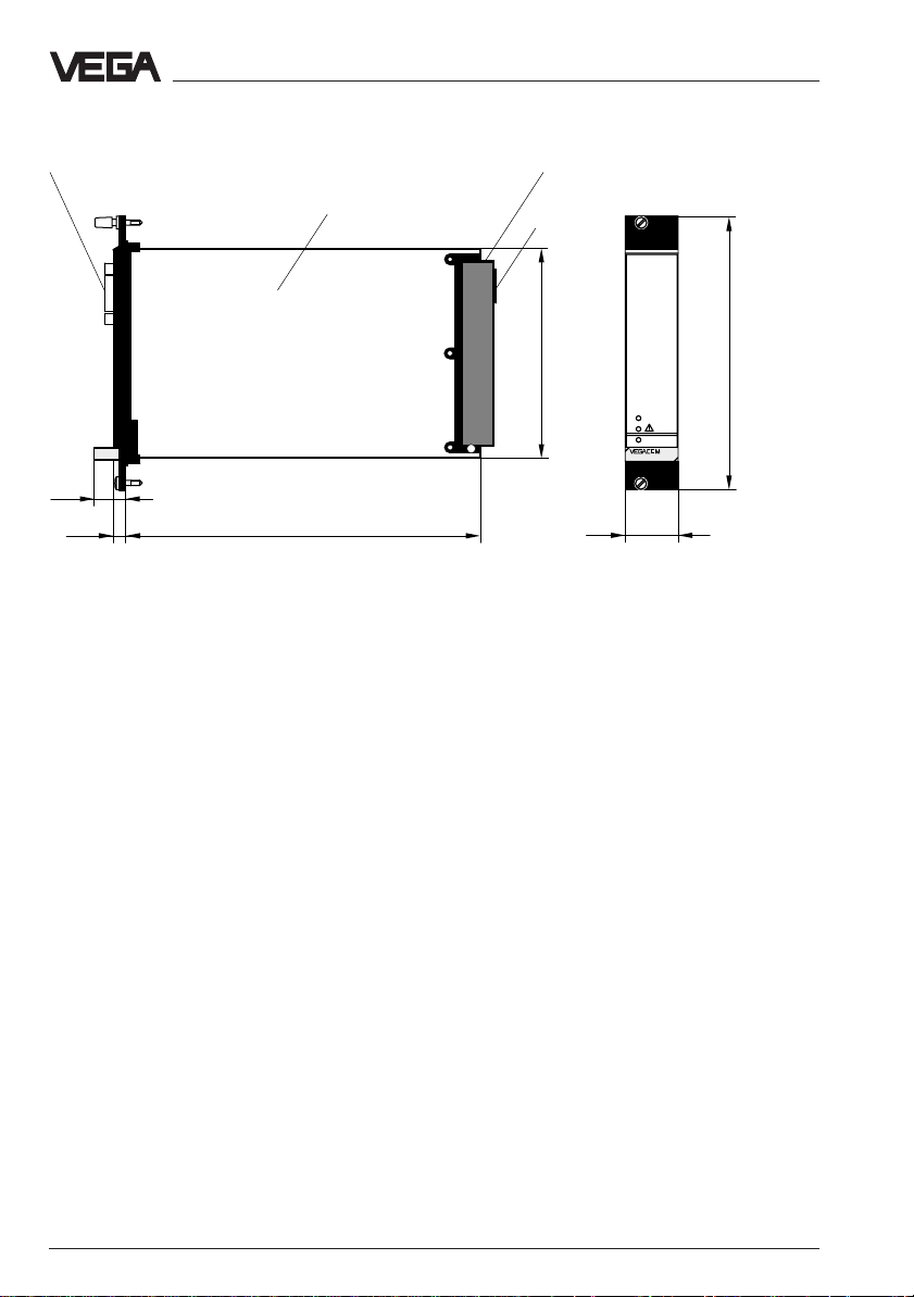
1.6 Dimensions
front RS 232C interface (PC)
Multipoint connector
100 x 160 x 1.5
European size
Multiple plug
LOGBUS
plug
Product description
5 TE
15
100
BA
on
1625,5
25,4
128,4
557
12 VEGACOM 557 VEGA ASCII
Page 13
Product description
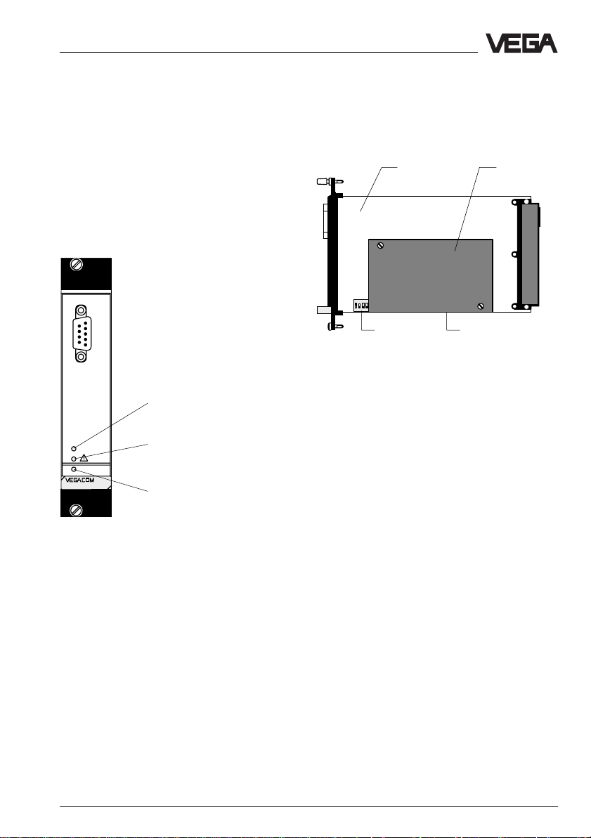
1.7 Indicating and adjustment elements
As diagnostic aid, VEGACOM 557 is
equipped with three LEDs. These are located
on the instrument front panel. In addition, the
basic board, as well as the additional board
of VEGACOM 557 are equipped with a
number of switches (DIP switch or hook
switch) for configuration of the available interfaces.
Indicating elements/Diagnostics LEDs
PC
VEGA ASCII active
BA
on
557
Fault signal
Voltage supply
Adjustment elements
The adjustment elements are located on the
basic board. A 6-pole DIL-switch block on
the basic board is used for adjustment of the
front PC interface.
Additional
Basic board
2 3 4ON1
DIL switch
on basic board
Side view of VEGACOM 557
DIL switch
on additional
board
board
Special function “Freeze Mode“
For diagnostic purposes on VEGA processing systems VEGAMET and VEGALOG, the
process image can be “frozen“ in VEGACOM
557 with the adjustment software VVO. This
enables the possibility of carrying out maintenance work on the VEGA system, without
disturbing the higher-priority processing
system.
Front of VEGACOM 557
Meaning of the LEDs:
VEGA ASCII active:
For activating the Freeze Mode, a PC must
be connected directly to the PC interface of
VEGACOM 557 and the Freeze Mode must
be switched on under VVO in the menu "Configuration - Measuring system“.
- green LED lights in case of valid data ex-
change
Fault signal:
- red LED flashing: DISBUS/LOGBUS-error
- irregularly flashing: no PC/DCS outputs
assigned
- permanent light: hardware error or special
Attention:
Before activating this function, you must
make sure that during this mode no disastrous consequences are to be expected for
production processes (during this mode, no
level values etc. are updated).
function "Freeze Mode“
Voltage supply:
- green LED lights, operating voltage on.
VEGACOM 557 VEGA ASCII 13
Page 14
2 Mounting and electrical
connection
Mounting and electrical connection
2.1 Mounting instructions
The gateway VEGACOM 557 can process
measured data and status information in two
different ways:
- via DISBUS (from measuring systems with
VEGAMET)
- via LOGBUS (from measuring systems
with VEGALOG).
For DISBUS configurations, VEGACOM 557
can be either mounted into carrier BGT 596
or housing type 505.
In conjunction with LOGBUS, VEGACOM 557
is mounted into carrier BGT LOG 571. The
location is individually selectable, the system
adapts automatically when rebooting
(autoconfiguation).
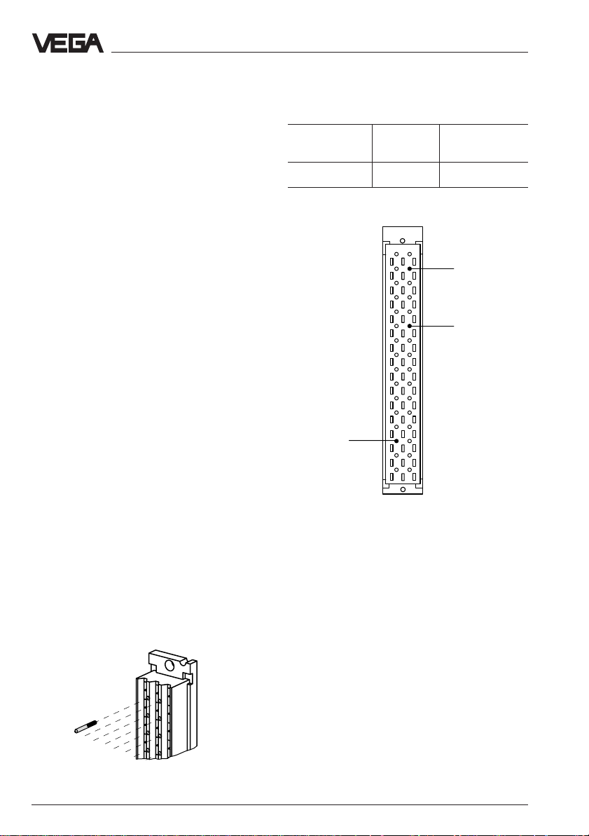
Coding
A mechanical coding system prevents mixing
up the different module cards in the carrier or
in the housing.
The coding system consists of:
- three coded pins in the multipoint connector
- three holes in the multiple plug of VEGACOM 557.
Instrument Function
coding coding
VEGACOM 557 a27 c3/c11
Instrument coding
d b z
a c
1
3
5
7
9
11
13
15
17
19
21
23
VEGACOM 557
Positioning of the coded pins
a27
25
27
29
31
Function coding
c3
c11
VEGALOG card
Interface card
The coded pins are attached to the module
or the housing. The plug-in socket must be
equipped by the user with the coded pins
according to the following table and diagram.
Coded pin
Plug-in socket of VEGACOM 557
14 VEGACOM 557 VEGA ASCII
Page 15
Mounting and electrical connection
2.2 Mounting in carrier and housing
BGT 596 or BGT LOG 571
For mounting, a slot module must be provided at the location. A slot module consists
of:
- a multipoint connector acc. to DIN 41 612,
series F, 33-pole (d, b, z)
- two screws
- three coded pins
- two guide rails.
The multipoint connector is available in the
following versions:
- Wire-Wrap, standard connection
1.0 mm x 1.0 mm
- plug connection
2.8 mm x 0.8 mm
- Termi-Point standard connection
1.6 mm x 0.8 mm
- soldering connection
- screw terminals 0.5 mm2.
For mounting the module, please note the
operating instructions of the carrier.
Housing type 505, type 506
This housing is already equipped with a
multipoint connector. Before mounting, please
check if the housing is equipped with a
power supply unit or not.
2.3 Wiring plan VEGA COM 557
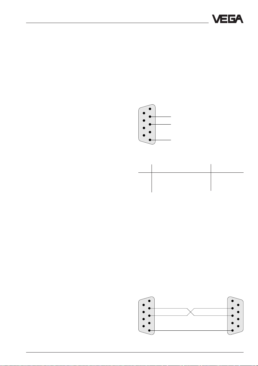
PC interface in front panel (SUB-Dplug)
The PC interface of VEGACOM 557 is used
exclusively for connection of computer systems with VEGA adjustment software via a
COM-Port. The PC interface is based on the
RS 232C standard and is assigned as follows.
1
6
2
7
3
8
4
9
5
Pin assignments of the PC interface of VEGACOM 557
Pin Description I/O
2 RxD receive data I
3 TxD transmit data O
5 GND ground –
Note:
With a direct connection to the computer
system, VEGACOM 557 works without hardware handshake.
RxD
TxD
GND
The connection is made via screw terminals
with max. 1.5 mm2. Further details are stated
in the operating instructions “Housing type
505, type 506“.
Direct connection
For direct connection of a PC to the PC interface of VEGACOM 557, the interlink (or a
standard) cable available from VEGA with 9pole plugs on both ends should be used.
The pin assignments of the interlink cable are
shown in the diagram.
1
6
2
7
3
8
4
9
5
Wiring proposal for interlink cable
1
2
3
4
5
VEGACOM 557 VEGA ASCII 15
6
7
8
9
Page 16
Mounting and electrical connection
dbz
10
8
6
4
2
12
14
16
18
20
22
24
26
28
30
32
Connection via modem
VEGA ASCII via RS 485
For remote parameter adjustment, it is possible to connect the PC interface via a modem.
In such a case, the modem cable that comes
with the respective modem should be used.
Modem operation is supported by VEGACOM 557 from software version 2.11. Further
information on the remote parameter adjustment is stated in the operating instructions
"Remote parameter adjustment“.
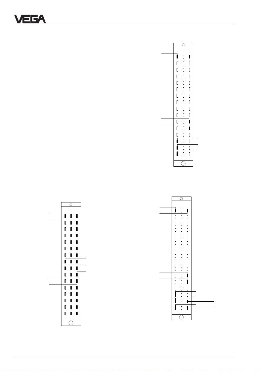
Connections of the multiple plug (rear)
For connection of VEGACOM 557 to the existing VEGA ASCII system all standard interfaces are available. The power supply of the
instrument and the connection to the VEGA
system are always the same. The following
illustrations show the respective terminal
assignments depending on the selected
Supply voltage
DISBUS (not
used on VEGALOG)
+
–
+
–
2
4
6
8
10
12
14
16
18
20
22
24
26
28
30
32
dbz
GND (C/C´)
DATA (B/B´)
/DATA (A/A´)
interface type.
Wiring regulation for VEGA ASCII via
VEGA ASCII via RS 232 C
Supply voltage
DISBUS (not
used on VEGALOG)
Wiring regulation for VEGA ASCII via
2
4
6
8
10
12
14
16
18
20
22
24
26
28
30
32
dbz
GND
TxD
RxD
RS 232 CRS 232 C
RS 232 C
RS 232 CRS 232 C
Supply voltage
+
–
DISBUS (not
used on VEGALOG)
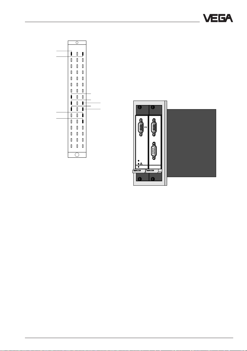
Wiring regulation for VEGA ASCII via
16 VEGACOM 557 VEGA ASCII
+
–
VEGA ASCII via RS 422
+
–
+
–
RS 485RS 485
RS 485
RS 485RS 485
GND
RX
/RX
RS 422RS 422
RS 422
RS 422RS 422
TX
/TX
Page 17
Mounting and electrical connection
Modbus via TTY
Supply voltage
DISBUS (not
used on VEGALOG)
+
–
+
–
dbz
2
4
6
8
10
12
14
16
18
20
22
24
26
28
30
32
Wiring regulation for VEGA ASCII via
GND
T+
R-
TTYTTY
TTY
TTYTTY
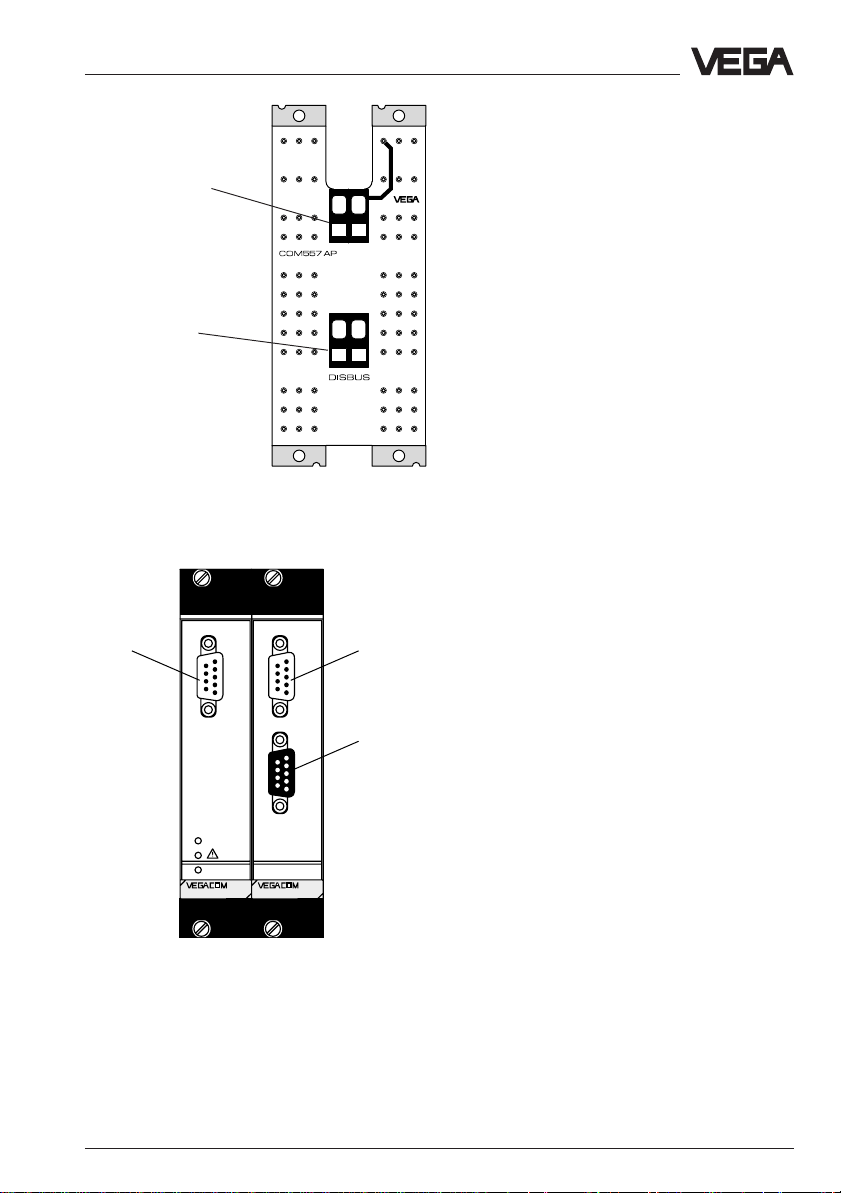
2.4 Mounting and installation instructions with VEGACOM 557AP
As an option, VEGACOM 557 can be extended with the adapter print VEGACOM
557AP. The adapter print VEGACOM 557AP
consists of a module card with 5 TE width
and two modules connected to a back-panel
print for carrier BGT 596 or BGT LOG 571.
R+
T-
BA
on
557AP
557
VEGACOM 557 with adapter print VEGACOM 557AP
With the adapter print card it is possible to
put the interfaces of VEGACOM 557 at the
front of the carrier. On the front of the adapter
print card, the VEGA ASCII interface is available as a 9-pole SUB-D-plug and as 9-pole
SUB-D-socket. The required interface type
must be stated when ordering VEGACOM
557AP.
The following interface types are available:
- RS 232
- RS 422
- RS 485
- TTY
VEGACOM 557 VEGA ASCII 17
Page 18
Mounting and electrical connection
Make sure that also VEGACOM 557 is set to
the same interface type (DIL-switch 1 on the
additional board) as VEGACOM 557AP. The
pin assignments of SUB-D-plug and SUB-Dsocket is listed in the tables.
Pin assignments
Pin-Nr. RS 232 RS422 RS485 TTY
1
2 RXD RX
3 TXD TX DATA R+
4
5 GND GND GND GND
6 - - +5V 7-/RX-T8 - /TX /DATA R9-- - -
9-pole SUB-D-plug
Pin-Nr. RS 232 RS422 RS485 TTY
1
2 TXD RX
3 RXD TX DATA R+
4
5 GND GND GND GND
6 - - +5V 789-- - -
9-pole SUB-D-socket
VEGACOM 557APVEGACOM 557AP
VEGACOM 557AP
VEGACOM 557APVEGACOM 557AP
----
----
----
----
/RX
/TX /DATA R-
-
-
-
T+
T+
T-
Mounting instructions for VEGA COM
557AP
The two modules connected to the backpanel print consist of:
- two multipoint connectors acc. to DIN 41
612, series F, 48-pole (d, b, z) connected
via the back-panel print
- four screws
- six coded pins
- four guide rails
Coding
The coding should be carried out for both
modules as described in chapter “2.1“.
Module position
BGT LOG 571
The module position is individually selectable,
the VEGALOG 571 processing system
adapts automatically through
autoconfiguration during the first booting.
After autoconfiguration, the slot location of the
cards must never be changed.
BGT 596
The module position is individually selectable.
Please note that the two connected modules
cover a width of 10 TE (5 TE for VEGACOM
557 plus 5 TE for the adapter board
VEGACOM 557AP).
Connection VEGACOM 557AP
BGT LOG 571
With the bus board (part of the carrier BGT
LOG 571) connection to LOGBUS is made
automatically when inserting VEGACOM 557.
The voltage supply of the card must be provided separately. For this reason, a 2-pole
terminal with tension spring connection,
called U
print. The permissible operating voltage of
VEGACOM 557 should be observed. In case
of DC voltage supply, the correct polarity
should be noted!
BGT 596
When operating VEGACOM 557 as
DISBUS participant, the DISBUS must be
wired in addition to the supply voltage.
For the two cables of the DISBUS, a 2-pole
terminal with tension spring connection is
available. Make sure that the polarity is correct!
is available on the back-panel
b,
18 VEGACOM 557 VEGA ASCII
Page 19
Mounting and electrical connection
Terminals
for supply voltage
Terminals
for DISBUS
View of back-panel board (rear of the carrier)
PC interface of
VEGACOM 557
Ub+
VEGA ASCII
interface of
VEGACOM 557 as
SUB-D-plug
PC
BA
on
557
VEGA ASCII
interface of VEGACOM 557 as SUBD-socket
557AP
Front view with SUB-D-connections of VEGACOM 557
and VEGACOM 557AP
VEGACOM 557 VEGA ASCII 19
Page 20
3 Switch settings on
VEGACOM 557
Switch settings on VEGACOM 557
For adjustment of the interfaces or the BUS
parameters of the PC interface and the VEGA
ASCII interfaces, various DIL switches are
provided on VEGACOM 557. Before inserting
VEGACOM 557 into the carrier or the housing, the DIL switches must be set according
to the user-specific data. The data of these
settings will be effective with the next initialization (switching on of voltage).
3.1 Adjustment of the PC interface
For adjustment of the RS 232 PC interface in
the front panel of VEGACOM 557, a 6-pole
DIL switch block is located on the basic
board. The PC interface is used for communication between a PC and VEGACOM 557, by
means of the adjustment software VVO or the
visualisation software VV.
Basic board
2 3 4ON1
DIL switch
on basic board
Side view of VEGACOM 557
Data format
Parity can be switched from even to no
parity (note for VVO including version 2.15,
even parity is compulsory).
Additional
board
DIL switch
below additional
board
Instrument number
Only relevant when operating two
VEGACOM 557 on the same DISBUS. If
two VEGACOM 557 are operated on the
DISBUS, different instrument numbers
have to be assigned.
Not relevant for operation on LOGBUS.
Automatic modem initialization
In position "ON“ the modem will be initialized automatically when connecting it to the
VEGACOM interface.
Transmission rate
For VVO or VV, the transmission rate must
be set to 9600 baud.
In the following diagram, you see all possible
adjustment possibilities for configuration of
the PC interface.
ON EDG
1
23456
Possible settings of the DIL switch on the basic
board
Factory setting
Data format
8 data bits, 1 stop bit, even parity
8 data bits, 1 stop bit, no parity
Instrument number
1. instrument
2. instrument
Automatic modem initialisation
On
Off
Transmission rate (baud)
300 4800
600 9600
1200 19200
2400 38400
20 VEGACOM 557 VEGA ASCII
Page 21

Switch settings on VEGACOM 557
123
45678
O
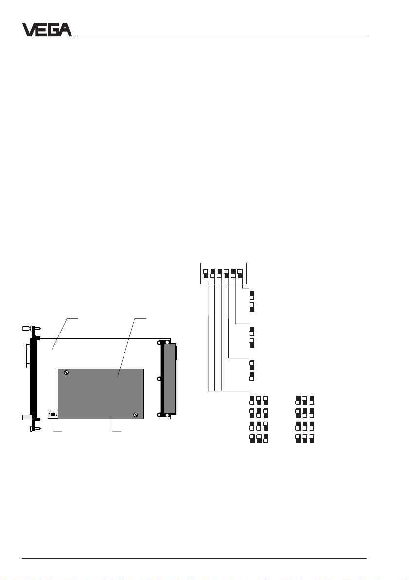
3.2 Adjustment of the VEGA ASCII interface
Three 8-pole DIL switch blocks as well as two
hook switches for configuration of the VEGA
ASCII interface to the DCS or the PLC are
located on the additional board.
DIL switch blocks
Additional
board
Front
DIL switch
plate
basic board
Bottom view of VEGACOM 557
additional board
1 2 3
1 2 3 4 5 6 7 8 1 2 3 4 5 6 7 8 1 2 3 4 5 6 7 8
Basic board
The following adjustments for the VEGA
ASCII are made through these DIL-switch
blocks:
Switch 1
- selection of the interface type
- activation of the bus termination
- selection of the protocol
Switch 2
- selection of the baud rate
- number of data bits
- mode for parity bit
- resolution
- definition of the measured value image
Hook switches
additional
board
2 1
Multiple plug
DIL switch block 1
(additional board)
N
Factory setting
Protocol selection
VEGA ASCII
Bus termination for RS 485/
422
On
Off
Selection of the interface type
RS 232
RS 422, RS 485
TTY
Possible settings of DIL switch block 1 on the additional board
Note:
When selecting the interfaces TTY and
RS 232, the hook switches must also be set
to the respective position.
Activation of the bus termination on RS 485 is
necessary when VEGACOM 557 is the last
participant. General rule: The first and the last
bus participant must be operated with bus
termination activated.
When using interface RS 422, the bus termination must always be activated on VEGACOM 557.
Switch 3
- VEGA ASCII address of VEGACOM 557
Note:
When holding VEGACOM 557 for adjustment
of the DIL-switches 1 to 3 (shown in illustration 2.10), the following switch representation
can be applied directly.
VEGACOM 557 VEGA ASCII 21
Page 22

Switch settings on VEGACOM 557
123
45678
O
123
45678
O
DIL switch block 2
(additional board)
N
Factory setting
DCS measured value image
(only relevant on VEGAMETs)
all meas. values Met 1,
all meas. values Met 2,
etc.
1. meas. value Met 1,
1. meas. value Met 2,
etc.
Protocol mode
Modbus ASCII
Modbus RTU
Parity
none
odd
even
Number of data bits
8
7
Selection of the baud rate
300
600
DIL switch block 3
(additional board)
N
Factory setting
Bus address
of VEGACOM 557
(Adr. 1 to 9)
not used
e.g.:
Adr.
= 1
Possible settings of DIL switch block 3 on additional
board
Note:
With the switch for the adjustment of the bus
address (DIL-switch block 3), it is theoretically possible to set addresses in the range
of 0 to 15. However, in reality only address 1
to 9 can be directly set. Address settings
outside the range are converted to address
9.
Address 0 cannot be used, as it is used as
broadcast address.
Hook switches (additional board)
The hook switches on the additional board
enable selection between TTY and RS 232
interface. The additional print has to be removed from the basic print to modify the
settings. The following illustration shows the
removed additional print.
1200
2400
4800
9600
19200
38400
Possible settings of DIL switch block 2 on additional
board
DIL switch
123
L RL R
12
Hook switch
View of the dismounted additional print
22 VEGACOM 557 VEGA ASCII
Page 23

Switch settings on VEGACOM 557
Depending on the requirements, the VEGA
ASCII interface can be used as TTY interface
but also as RS 232 interface (using the hook
switches). Illustration 2.15 shows the respective switch positions. As a rule, VEGACOM
557 is delivered with RS 232 activated.
L RL R
= Activation of the TTY-interface
12
L RL R
= Activation of the RS 232-interface
(default)
12
Note:
L = left position, R = right position
Allocation of the switch positions (hook switch on the
additional print)
VEGACOM 557 VEGA ASCII 23
Page 24

4 Data image in VEGACOM 557
Data image in VEGACOM 557
VEGACOM 557 collects the measured values
of the VEGA signal conditioning instruments
VEGAMET 509, 512, 513, 514, 515 and 614
(via DISBUS) or VEGALOG 571 (via LOGBUS) and puts them in the temporary
memory for collection via the VEGA ASCII.
The method of storing the measured values
(for the higher-priority processing systems)
in the VEGACOM 557 temporary memory
differs depending on the selected configuration. It depends on whether VEGACOM 557
is connected to the DISBUS or the LOGBUS,
and if DISBUS, also on the connected instrument type. However, it can be also influenced
by VEGACOM 557 itself via DIL switches.
Note
On the VEGAMET 513, 514, 515 and 614
signal conditioning instruments, as well as on
the VEGALOG 571 processing system, the
individual configuration of the DCS outputs
with the adjustment software VVO is possible.
On VEGAMET 513, 514, 515 and 614 signal
conditioning instruments as well as the VEGALOG 571 processing system, it is additionally possible to enquire the conditions of
the contact inputs and outputs via VEGACOM 557.
Enquiry of DCS values from DISBUS
The addressing of the measured values for
VEGA ASCII is made instrument-orientated
for the DISBUS enquiry. I.e. the measured
values are enquired individually for each
VEGAMET.
Due to these two different series, it is necessary to use two different telegrams for the
enquiry of measured values. With enquiry "P“
3 values are transmitted. With enquiry "M“,
VEGACOM 557 delivers a total of 7 measured values.
If one or several DCS outputs have been
assigned on the instrument, the respective
measured value is provided with an error
information during transmission. It is then
possible to distinguish between valid and
invalid values.
All values of an instrument are placed one
after the other.
Resolution
A selection between two resolutions of the
value range is possible:
1 low resolution: (switch 2.2 = OFF)
between -999.9 and +999.9
2 high resolution: (switch 2.2 = ON)
between -999999 and +999999
(actually only the range between
-32768 and +32767 is used)
In addition to the above mentioned possibilities, the DCS values can be read out as a
block. Here also there are two different possible configurations.
In the first configuration, a total of 16 DCS
values are reserved for each VEGAMET. The
instruments are then imaged in the memory
according to their address.
Series 509 and 512 instruments deliver max.
3 measured values. The number of measured
values can be configured on the instrument.
On series 513, 514, 515 and 614 instruments,
the number of measured values (max. 7) can
be set via the adjustment program VVO or
directly on the instrument.
24 VEGACOM 557 VEGA ASCII
Page 25

Data image in VEGACOM 557
all measured values
of VEGAMET #1
all measured values
of VEGAMET #2
all measured values
of VEGAMET #15
ESC OK
VEGAMET
%
100
+
-
CONNECT
!
on
513
ESC OK
VEGAMET
%
%
100
100
+
+
-
-
ESC OK
CONNECT
CONNECT
!
!
on
on
VEGAMET
513
513
-
ESC OK
VEGAMET
%
100
+
CONNECT
!
on
513
Grouping of measured values acc. to VEGAMET
addresses
The second configuration images first all DCS
values with the number 1, then DCS values
with the number 2 etc.
all DCS output with index =1
Enquiry of DCS values on LOGBUS
The numbering of the DCS values is made for
LOGBUS between 001 and 255. This assignment is prepared via the parameter tool VVO.
Each DCS value is therefore marked clearly.
With the enquiry "%“ and the DCS number,
the values can be read out of VEGACOM 557
as single enquiry, range enquiry or as total
block.
all DCS output with index =2
ESC OK
VEGAMET
%
100
+
-
CONNECT
!
on
513
ESC OK
VEGAMET
%
%
100
100
+
+
-
-
ESC OK
CONNECT
CONNECT
!
!
on
on
VEGAMET
513
513
-
ESC OK
VEGAMET
%
100
+
CONNECT
!
on
513
Grouping of measured values acc. to DCS indices or
channels
VEGACOM 557 VEGA ASCII 25
Page 26

Data image in VEGACOM 557
4.1 Enquiry for VEGAMET with three or less values per instrument
Low resolution = Switch 2.2 = OFF
VEGAMET series 509 and 512 instruments have max. 3 DCS outputs. Series 513, 514 and 515
instruments can assign max. 7 DCS outputs. If max. 3 DCS outputs are used with these instruments, the following telegram can be used for data transmission:
Telegram from processing system to VEGACOM 557
Address Address End
Identifier VEGACOM VEGAMET identification
No. of bytes1121
Range (AS CII) p (P) 0..9 01. . 15 CR
Example p 1 02 CR
Identifier: 1 character, optional "P“ or "p“
End identification: 1 character Chr (13) = CR = Carriage Return
Total length of the telegram: 5 characters
Answer of VEGACOM 557
Addr Addr DCS DCS DCS Error End
S1 COM MET S2 va lue1 T1 value2 T2 v alue3 T3 info identification
No. of bytes11 11717171 1 2
Range (ASCII) = 0.. 9 01. .15 # AS CII p AS CII p ASCII p 0.. 7 CRLF
Example = 1 02 # 17.2 p 38.4 p 45.7 p 0 CRLF
Start character: S1 = 1 character "=“
Start character: S2 = "#“
Separating character: T1, T2, T3 = per 1
character "p“
Total length of the telegram: 32 characters
26 VEGACOM 557 VEGA ASCII
(structure also value for DCS value 2 and 3)
7123456
3 positions in front of the decimal point
1 decimal point
1 position after the decimal point
1 during simulation
" " during operation
"-“ for negative values
" " for positive values
Error information
0: No error
1: Error on DCS 1
2: Error on DCS 2
3: Error on DCS 1+2
4: Error on DCS 3
5: Error on DCS 1 + 3
6: Error on DCS 2 + 3
7: Error on DCS 1,2 + 3
Page 27

Data image in VEGACOM 557
5
High resolution = switch 2.2 = ON
The same enquiry can also be carried out with high resolution. The enquiry to VEGACOM 557
remains the same, in the answer more characters are used for the presentation of the measured value.
Telegram from processing system to VEGACOM 557
Address Address End
Identifier VEGACOM VEGAMET identification
No. of bytes1121
Range (ASCII) p (P) 0. .9 01. .15 CR
Example p 1 02 CR
Identifier: 1 character, optional "P“ or "p“
End identification: 1 character Chr (13) = CR = Carriage Return
Total length of the telegram: 5 characters
Answer of VEGACOM 557
Addr Addr DCS DCS DCS Error End
S1 COM MET S2 Value1T1 Value2 T2 Valu e3 T3 info identification
No.of bytes11117171711 2
Range (ASCII) = 0.. 9 01..1
# ASCII p ASCII p ASCII p 0..7 CRLF
Example = 1 02 # 00172 p 00384 p 00457 p 0 CRLF
Start character: S1 = 1 character "=“
Start character: S2 = "#“
Separating character: T1,T2,T3 = per 1 character "p“
Total length of the telegram: 32 characters
VEGACOM 557 VEGA ASCII 27
(structure also value for DCS value 2 and 3)
123456
6 digit figure
without decimal point
"-“ for negative values
" " for positive values
7
Error information
0: No error
1: Error on DCS 1
2: Error on DCS 2
3: Error on DCS 1+2
4: Error on DCS 3
5: Error on DCS 1 + 3
6: Error on DCS 2 + 3
7: Error on DCS 1,2 + 3
Page 28

Data image in VEGACOM 557
4.2 Enquiry for VEGAMET with up to seven values per instrument
Low resolution = switch 2.2 = OFF
VEGAMET instruments can be provided with up to 7 DCS outputs. With this telegram, it is
possible to read all DCS values from one instrument.
Telegram from processing system to VEGACOM 557
Address Address End
Identifier VEGACOM VEGAME T identification
No. of bytes1121
Range (AS CII) m (M) 0.. 9 01. . 15 CR
Example m 1 2 CR
Identifier: 1 character, optional "M“ or "m“
End identification: 1 character Chr (13) = CR = Carriage Return
Total length of the telegram: 5 characters
Answer of VEGACOM 557
Addr Addr DCS Error End
S1 COM MET S2 value2 T2 T3 info identification
No. of bytes 1 1 1 1 7 X 7 1 1 1 2
Range (ASCII) = 0..9 01..15 # ASCII p p 0..7 CRLF
Example = 1 02 # 38.4 p p 0 CRLF
Start character: S1 = 1 character "=“
Start character: S2 = 1 character "#“
Separating character: Tx = per 1 character "p“
Total length of the telegram: 66 characters
28 VEGACOM 557 VEGA ASCII
(Structure is valid for all DCS values)
123456
3 positions in front of decimal point
1 decimal point
1 position after the decimal point
1 during simulation
" " during operation
"-“ for negative values
" " for positive values
7
Error information
1. position
0: No error on DCS 1,2,3
1: Error on DCS 1
2: Error on DCS 2
3: Error on DCS 1+2
4: Error on DCS 3
5: Error on DCS 1 + 3
6: Error on DCS 2 + 3
7: Error on DCS 1,2 + 3
2. position
0: No error on DCS 4,5,6
1: Error on DCS 4
2: Error on DCS 5
3: Error on DCS 4+5
4: Error on DCS 6
5: Error on DCS 4 + 6
6: Error on DCS 5 + 6
7: Error on DCS 4,5 + 6
3. position
0: No error on DCS 7
1: Error on DCS 7
Page 29

Data image in VEGACOM 557
High resolution = switch 2.2 = ON
The same resolution can also be carried out with high resolution. The enquiry to VEGACOM
557 remains the same, however the answer, has more characters for the presentation of the
measured value.
Telegram from processing system to VEGACOM 557
Address Address End
Identifier VEGACOM VEGAMET identification
No. of bytes1121
Range (ASCII) m (M ) 0..9 01..15 CR
Example m 1 2 CR
Identifier: 1 character, optional "M“ or "m“
End identification: 1 character Chr (13) = CR = Carriage Return
Total length of the telegram: 5 characters
Answer of VEGACOM 557
Addr Addr DCS Error End
S1 COM MET S2 v alue2 T2 T3 info identification
No. of bytes 1 1 1 1 7 X 7 1 1 1 2
Range (ASCII) = 0..9 01.. 15 # ASCII p p 0.. 7 CRLF
Example = 1 02 # -00384 p p 0 CRLF
Start character: S1 = 1 character "=“
Start character: S2 = 1 character "#“
Separating character: Tx = per 1 character "p“
Total length of the telegram: 66 characters
VEGACOM 557 VEGA ASCII 29
(structure is valid for all DCS values)
7123456
6 digit figure
without decimal point
"-“ for negative values
" " for positive values
Error information
1. position
0: No error on DCS 1,2,3
1: Error on DCS 1
2: Error on DCS 2
3: Error on DCS 1+2
4: Error on DCS 3
5: Error on DCS 1 + 3
6: Error on DCS 2 + 3
7: Error on DCS 1,2 + 3
2. position
0: No error on DCS 4,5,6
1: Error on DCS 4
2: Error on DCS 5
3: Error on DCS 4+5
4: Error on DCS 6
5: Error on DCS 4 + 6
6: Error on DCS 5 + 6
7: Error on DCS 4,5 + 6
3. position
0: No error on DCS 7
1: Error on DCS 7
Page 30

Data image in VEGACOM 557
4.3 Enquiry as block with low resolution
Low resolution = switch 2.2 = OFF
This telegram reads in all DCS values, i.e. 255 values are always transferred together. Each
DCS value is provided with a number. Depending on the position of switch 2.1, the DCS values are arranged differently. The assignment of the DCS numbers to the VEGAMET addresses is stated in supplement A.
Telegram from processing system to VEGACOM 557
End
Identifier identification
No. of bytes 1 1
Range (AS CII) % CR
Example % CR
Identifier: 1 character, "%“
End identification: 1 character Chr (13) = CR = Carriage Return
Total length of the telegram: 2 characters
Answer of VEGACOM 557
255 repetitions
DCS DCS End
S1 no. S2 value2 identification
No. of by t es 1 3 1 5-6 2
DCS value or
Range (ASCII) = 001..255 #
fault %CR
Example = 001 # -067.3 %CR
Start character: S1 = 1 character "=“
Start character: S2 = 1 character "#“
Total length of the telegram: 255 * 12 or 13 characters
Fault
12345
‘FAULT’
30 VEGACOM 557 VEGA ASCII
valid measured value
123456
3 positions in front of the decimal point
1 decimal point
1 position after the decimal point
‘-’ with negative values
‘ ‘ with positive values
Page 31

Data image in VEGACOM 557
High resolution = switch 2.2 = ON
The same enquiry can also be carried out with high resolution. The enquiry to VEGACOM 557
remains the same, however in the answer, more characters are used for presentation of the
measured value.
Telegram from processing system to VEGACOM 557
End
Identifier identification
No. of bytes 1 1
Range (AS CII) % CR
Example % CR
Identifier: 1 character, "%“
End identification: 1 character Chr (13) = CR = Carriage Return
Total length of the telegram: 2 characters
Answer of VEGACOM 557
255 repetitions
DCS DCS End
S1 no. S2 value2 identification
No. of by t es 1 3 1 7 2
DCS value of
Range (ASCII) = 001..255 #
fault %CR
Example = 001 # -000673 %CR
Start character: S1 = 1 character "=“
Start character: S2 = 1 character "#“
Total length of the telegram: 255 * 14 characters
Fault
‘FAULT ’
VEGACOM 557 VEGA ASCII 31
valid measured value
12345671234567
6 digit value
‘-’ with negative values
‘ ‘ with positive values
Page 32

Data image in VEGACOM 557
4.4 Enquiry as single value with low resolution
Low resolution = switch 2.2 = OFF
This telegram reads in a DCS value from VEGACOM 557. Depending on the position of switch
2.1., the DCS values are arranged differently. The assignment of the DCS numbers to the
VEGAMET addresses is stated in supplement A.
Telegram from processing system to VEGACOM 557
DCS End
Identifier number identification
No. of byt e s 1 3 1
Range (ASCII) % 001..255 CR
Example % 001 CR
Identifier: 1 character, "%“
End identification: 1 character Chr (13) = CR = Carriage Return
Total length of the telegram: 5 characters
Answer of VEGACOM 557
One repetition
DCS DCS End
S1 no. S2 value2 identification
No. of by t es 1 3 1 5-6 2
DCS value or
Range (ASCII) = 001..255 #
fault %CR
Example = 001 # -067.3 %CR
Start character: S1 = 1 character "=“
Start character: S2 = 1 character "#“
Total length of the telegram: 12 or 13 characters
Fault
12345
‘FAULT’
32 VEGACOM 557 VEGA ASCII
valid measured value
123456
3 positions in front of the decimal point
1 decimal point
1 position after the decimal point
"-“ with negative values
" " with positive values
Page 33

Data image in VEGACOM 557
High resolution = switch 2.2 = ON
The same enquiry can also be carried out with high resolution. The enquiry to VEGACOM 557
remains the same, however in the answer, more characters are used for the presentation of
the measured value.
Telegram from processing system to VEGACOM 557
DCS End
Identifier number identification
No. of bytes 1 3 1
Range (A SCII) % 00 1..255 C R
Exam ple % 001 CR
Identifier: 1 character, "%“
End identification: 1 character Chr (13) = CR = Carriage Return
Total length of the telegram: 5 characters
Answer of VEGACOM 557
One repetition
DCS DCS End
S1 no. S2 value2 identification
No. of by t es 1 3 1 7 2
DCS value or
Range (ASCII) = 001..255 #
fault %CR
Example = 001 # -000673 %CR
Start character: S1 = 1 character "=“
Start character: S2 = 1 character "#“
Total length of the telegram: 13 characters
Fault
‘FAULT ’
VEGACOM 557 VEGA ASCII 33
valid measured value
12345671234567
6 digit figure
"-“ with negative values
" " with positive values
Page 34

Data image in VEGACOM 557
4.5 Enquiry as range with low resolution
Low resolution = switch 2.2 = OFF
This telegram reads in a DCS value from VEGACOM 557. Depending on the position of the
switch 2.1, the DCS values are arranged differently. The assignment of the DCS numbers to
the VEGAMET addresses is stated in supplement A.
Telegram from processing system to VEGACOM 557
DCS End
Identifier number T1 Number identification
No. of bytes 1 3 1 3 1
Range (ASCII) % 001.. 255 L 001. .255 CR
Example % 001 L 001 CR
Identifier: 1 character, "%“
T1 : Separating character = 1 character "L“
End identification: 1 character Chr (13) = CR = Carriage Return
Total length of the telegram: 9 characters
Answer of VEGACOM 557
n (n= stated number) repetitions
DCS DCS End
S1 no. S2 value2 identification
No. of by t es 1 3 1 5-6 2
DCS value or
Range (ASCII) = 001..255 #
fault %CR
Example = 001 # -067.3 %CR
Start character: S1 = 1 character "=“
Start character: S2 = 1 character "#“
Total length of the telegram: 12 or 13 characters
Fault
12345
‘FAULT’
34 VEGACOM 557 VEGA ASCII
valid measured value
123456
3 positions in front of the decimal point
1 decimal point
1 position after the decimal point
"-“ with negative values
" " with positive values
Page 35

Data image in VEGACOM 557
High resolution = switch 2.2 = ON
The same enquiry can also be carried out with high resolution. The enquiry to VEGACOM 557
remains the same, however in the answer, more characters are used for the presentation of
the measured value.
Telegram from processing system to VEGACOM 557
DCS End
Identifier number T 1 Number identification
No. of bytes 1 3 1 3 1
Range (ASCII) % 001. . 255 L 001. . 255 CR
Example % 001 L 001 CR
Identifier: 1 character, "%“
T1 : Separating character = 1 character "L“
End identification: 1 character Chr (13) = CR = Carriage Return
Total length of the telegram: 9 characters
Answer of VEGACOM 557
n (n= stated number) repetitions
DCS DCS End
S1 no. S2 value2 identification
No. of by t es 1 3 1 7 2
DCS value or
Range (ASCII) = 001..255 #
fault %CR
Example = 001 # -000673 %CR
Start character: S1 = 1 character "=“
Start character: S2 = 1 character "#“
Total length of the telegram: n * 14 characters
Fault
‘FAULT ’
VEGACOM 557 VEGA ASCII 35
valid measured value
12345671234567
6 digit figure
"-“ with negative values
" " with positive values
Page 36

Data image in VEGACOM 557
4.6 Enquiry as block with address and low resolution
Low resolution = switch 2.2 = OFF
This telegram reads in all DCS values of VEGACOM 557 with the assigned address, i.e. 255
are always transferred together. Each DCS value is provided with a number. Depending on
the position of switch 2.1, the DCS values are arranged differently. The assignment of the DCS
numbers to the VEGAMET addresses is stated in supplement A.
Telegram from processing system to VEGACOM 557
End
Identifier Address T1 identification
No. of bytes 1 1 1 1
Range (AS CII) % 0..9 , CR
Example % 2 , CR
Identifier: 1 character, "%“
T1: 1 character ",“ (comma)
End identification: 1 character Chr (13) = CR = Carriage Return
Total length of the telegram: 4 characters
Answer of VEGACOM 557
255 repetitions
DCS DCS End
S1 Adr T1 no. S2 value2 identification
No. of bytes 1 1 1 3 1 5-6 2
DCS valu e
Range (ASCII) = 0..9 , 001..255 #
or fault % CR
Example = 2 , 001 # -067.3 %CR
Start character: S1 = 1 character "=“
Address : Addr = 1 character VEGACOM 557 address
Separating character: T1 = 1 character ",“ (comma)
Start character: S2 = 1 character "#“
Total length of the telegram: 255 * 14 or 15 characters
Fault
12345
‘FAULT’
36 VEGACOM 557 VEGA ASCII
valid meas. value
123456
3 positions in front of the decimal point
1 decimal point
1 position after the decimal point
"-“ with negative values
" " with positive values
Page 37

Data image in VEGACOM 557
High resolution = switch 2.2 = ON
The same enquiry can also be carried out with high resolution. The enquiry to VEGACOM 557
remains the same, however in the answer, more characters are used for the presentation of
the measured value.
Telegram of processing system to VEGACOM 557
End
Identifier Address T1 identification
No. of bytes 1 1 1 1
Range (ASCII) % 0.. 9 , CR
Example % 2 , CR
Identifier: 1 character, "%“
T1: 1 character ",“ (comma)
End identification: 1 character Chr (13) = CR = Carriage Return
Total length of the telegram: 4 characters
Answer of VEGACOM 557
255 repetitions
DCS DCS End
S1 Adr T1 no. S2 v alue2 identification
No. of bytes111317 2
DCS value
Range (ASCII) = 0..9 , 001. .255 #
or fault %CR
Example = 2 , 001 # -000673 %CR
Start character: S1 = 1 character "=“
Address: Addr = 1 character VEGACOM 557 address
Separating character: T1 = 1 character ",“ (comma)
Start character: S2 = 1 character "#“
Total length of the telegram: 255 * 16 characters
Fault
‘FAULT ’
VEGACOM 557 VEGA ASCII 37
valid meas. value
12345671234567
6 digit figure
"-“ with negative values
" " with positive values
Page 38

Data image in VEGACOM 557
4.7 Enquiry as single value with address and low resolution
Low resolution = switch 2.2 = OFF
This telegram reads exactly one DCS value. Depending of the position of the switch 2.1, the
DCS values are arranged differently. The assignment of the DCS number to the VEGAMET
addresses is stated in supplement A. In addition to chapter "4.6 Enquiry as block with address and low resolution“, an address from 0 to 9 is transferred so that several VEGACOM
557 can be operated on one BUS system (e.g. via a RS 485 interface)
Telegram from processing system to VEGACOM 557
DCS End
Identifier Address T1 number identification
No. of bytes 1 1 1 3 1
Range (ASCII) % 0. .9 , 001..255 CR
Example % 2 , 001 CR
Identifier: 1 character, "%“
T1: 1 character ",“ (comma)
End identification: 1 character Chr (13) = CR = Carriage Return
Total length of the telegram: 7 characters
Answer of VEGACOM 557
One repetition
DCS DCS End
S1 Addr T1 no. S2 value2 identification
No. of bytes 1 1 1 3 1 5-6 2
DCS valu e
Range (ASCII) = 0..9 , 001..255 #
or fault % CR
Example = 2 , 001 # -067.3 %CR
Start character: S1 = 1 character "=“
Address: Addr = 1 character VEGACOM 557 address
Separating character: T1 = 1 character ",“ (comma)
Start character: S2 = 1 character "#“
Total length of the telegram: 14 or 15 characters
Fault
12345
‘FAULT’
38 VEGACOM 557 VEGA ASCII
valid meas. value
123456
3 positions in front of the decimal point
1 decimal point
1 position after the decimal point
"-“ with negative values
" " with positive values
Page 39

Data image in VEGACOM 557
High resolution = switch 2.2 = ON
The same enquiry can also be carried out with high resolution. The enquiry of VEGACOM 557
remains the same, however in the answer, more characters are used for the presentation of
the measured value.
Telegram from processing system to VEGACOM 557
DCS End
Identifier Address T1 number identification
No. of bytes 1 1 1 3 1
Range (ASCII) % 0..9 , 001.. 255 CR
Example % 2 , 001 CR
Identifier: 1 character, "%“
T1: 1 character ",“ (comma)
End identification: 1 character Chr (13) = CR = Carriage Return
Total length of the telegram: 7 characters
Answer of VEGACOM 557
One repetition
DCS DCS End
S1 Adr T1 no. S2 value2 identification
No. of bytes 1 1 1 3 1 7 2
DCS value
Range (ASCII) = 0. . 9 , 001.. 255 #
or fault %CR
Example = 2 , 001 # -000673 %CR
Start character: S1 = 1 character "=“
Address: Addr = 1 character VEGACOM 557 address
Separating character: T1 = 1 character ",“ (comma)
Start character: S2 = 1 character "#“
Total length of the telegram: 16 characters
Fault
‘FAULT ’
VEGACOM 557 VEGA ASCII 39
valid meas. value
12345671234567
6 digit figure
"-“ with negative values
" " with positive values
Page 40

Data image in VEGACOM 557
4.8 Enquiry as range with address and low resolution
Low resolution = switch 2.2 = OFF
This telegram reads in a range of DCS values. The number is transferred with the enquiry.
Depending on the position of the switch 2.1, the DCS values are arranged differently. The
assignment of the DCS numbers to the VEGAMET addresses is stated in supplement A. In
addition to chapter "4.6 Enquiry as block with address and low resolution“ another address
from 0 to 9 is transferred, so that several VEGACOM 557 can be operated on one BUS system (e.g. via a RS 485 interface).
Telegram from processing system to VEGACOM 557
DCS DCS End
Identifier Address T1 number T1 number identification
No. of bytes1 11313 1
Range (AS CII) % 0.. 9 , 0 01.. 2 55 L 001.. 255 CR
Example % 2 , 001 L 2 CR
Identifier: 1 character, "%“
T1: 1 character ",“ (comma)
T2: 1 character "L“
End identification: 1 character Chr (13) = CR = Carriage Return
Total length of the telegram: 11 characters
Answer of VEGACOM 557
n (n= stated number) repetitions
DCS DCS Ende
S1 Addr T1 no. S2 v alue2 identification
No. of byt es 1 1 1 3 1 5-6 2
DCS value
Range (ASCII) = 0. .9 , 001.. 255 #
or fault %CR
Example = 2 , 001 # -067.3 %CR
Start character: S1 = 1 character "=“
Address: Addr = 1 character VEGACOM 557 address
Separating character: S2 = 1 character ",“ (comma)
Start character: S3 = 1 character "#“
Total length of the telegram: 14 or 15 characters
Fault
1234
‘FAULT’
40 VEGACOM 557 VEGA ASCII
valid meas. value
5
12345
3 positions in front of the decimal point
1 decimal point
1 position after the decimal point
"-“ with negative values
" " with positive values
6
Page 41

Data image in VEGACOM 557
High resolution = switch 2.2 = ON
The same enquiry can also be carried out with high resolution. The enquiry to VEGACOM 557
remains the same, however in the answer, more characters are used for the presentation of
the measured value.
Telegram from processing system to VEGACOM 557
DCS DCS End
Identifier Address T1 number T1 number identification
No. of bytes1 11313 1
Range (ASCII) % 0.. 9 , 001..255 L 001.. 255 CR
Example % 2 , 001 L 2 CR
Identifier: 1 character, "%“
T1: 1 character ",“ (comma)
T2: 1 character "L“
End identification: 1 character Chr (13) = CR = Carriage Return
Total length of the telegram: 11 characters
Answer of VEGACOM 557
n (n= stated number) repetitions
DCS DCS End
S1 Addr T1 no. S2 value2 identification
No. of bytes 1 1 1 3 1 7 2
DCS valu e
Range (ASCII) = 0..9 , 001..255 #
or fault % CR
Example = 2 , 001 # -000673 %CR
Start character: S1 = 1 character "=“
Address: Addr = 1 characters VEGACOM 557 address
Separating character: S2 = 1 character ",“ (comma)
Start character: S3 = 1 character "#“
Total length of the telegram: 16 characters
Fault
‘FAULT ’
VEGACOM 557 VEGA ASCII 41
valid meas. value
12345671234567
6 digit figure
"-“ with negative values
" " with positive values
Page 42

Data image in VEGACOM 557
4.9 Enquiry for the contact inputs and outputs on DISBUS
During operation on DISBUS via VEGACOM 557, the contacts are assigned by means of the
VEGAMET address. The enquiry is then made with the VEGAMET address.
Telegram from processing system to VEGACOM 557 for enquiry of a VEGAMET
Address Address End
Identifier COM MET identification
No. of bytes 1 1 2 1
Range (ASCII) R 0..9 01.. 15 CR
Example R 2 01..15 CR
Telegram from processing system to VEGACOM 557 for enquiry of several VEGAMET
Address Address End
Identifier COM MET T1 No. identification
No. of bytes 1 1 2 1 2 1
Range (ASCII) R 0.. 9 01..15 L 01 ..15 CR
Example R 2 01 L 03 CR
Identifier: 1 character, "R“
T1: 1 character "L“
End identification: 1 character Chr (13) = CR = Carriage Return
Total length of the telegram: 5 or 8 characters
Answer of VEGACOM 557
1 or n (n= stated number) repetitions
Address Address Contact End
S1 COM MET S2 value T Status identification
No. of bytes 1 1 2 1 6 1 1
Range (ASCII) R 0. .9 01..15 # value p 0..3 CRLF
Example R 2 01 # 32896 p 0 CRLF
Start character: S1 = 1 character "=“
Address: Addr = 1 character VEGACOM 557 address
Start character: S2 = 1 character "#“
Status: Validity of the contact value,
0 = Inputs and outputs valid, 1 = output contacts valid,
2 = Input contacts valid, 3 = value invalid.
End identification: CR LF = Carriage Return + Linefeed
Total length of the telegram: 15 characters
Input contacts Output contacts
Meaning S1 reserve 2 1 S2 reserve ST 2 1
Bit position 15 14 13 12 11 10 9 8 7 6 5 4 3 2 1 0
ST : Fail safe relay
S1 : Status for input contacts; value : 0 - input contacts are valid, value :1 - input contacts are not valid.
S2 : Status for output contacts; value : 0 - output contacts are valid, value :1 - output contacts are not valid.
42 VEGACOM 557 VEGA ASCII
Contact value binary coded
32896 = 10000000 10000000
Page 43

Data image in VEGACOM 557
4.10 Enquiry for the contact inputs and outputs on LOGBUS
During operation on LOGBUS via VEGACOM 557, the contacts are assigned by means of the
module address. The enquiry is the made with the module address.
Telegram from processing system to VEGACOM 557 for enquiry of a module
Address Mod- End
Identifier COM ule identification
No. of bytes 1 1 2 1
Range (ASCII) R 0.. 9 01..31 CR
Example R 2 01..15 CR
Telegram of the processing system to VEGACOM 557 for enquiry of several modules
Address Address End
Identifier COM MET T 1 No. identification
No. of bytes 1 1 2 1 2 1
Range (ASCII) R 0..9 01..31 L 01..31 CR
Example R 2 01 L 03 CR
Identifier: 1 character, "R“
T1: 1 character "L“
End identification: 1 character Chr (13) = CR = Carriage Return
Total length of the telegram: 5 or 8 characters
Answer of VEGACOM 557
1 or n (n= stated number) repetitions
Address Mod- Contact End
S1 COM ule S2 value T Status identification
No. of bytes 1 1 2 1 6 1 1
Range (ASCII) R 0..9 01..31 # value p 0..1 CRLF
Example R 2 01 # 32896 p 0 CRLF
Start character: S1 = 1 character "=“
Address: Addr = 1 character VEGACOM 557 address
Start character: S2 = 1 character "#“
Status: Validity of the contact value,
0 = value valid, 1 = value invalid.
End identification: CR LF = Carriage Return + Linefeed
Total length of the telegram: 15 characters
Input contacts Output contacts
Meaning S1 reserve 10 9 8 7 6 5 4 3 2 1
Bit position 15 14 13 12 11 10 9 8 7 6 5 4 3 2 1 0
S1 : Status for contacts; 0 - contact information is valid, 1 - contact information is not valid.
VEGACOM 557 VEGA ASCII 43
Contact value binary coded
32768 = 10000000 00000000
Page 44

Data image in VEGACOM 557
4.11 Enquiry for the software version
With this enquiry, the software version in VEGACOM 557 can be determined.
Telegram from processing system to VEGACOM 557
Address End
Identifier VEGACOM Reserve Enquiry identification
No. of bytes 1 1 2 13 1
Range (ASCII) % 0..9 00 READ VERSION CR
Example % 2 00 READ VERSION CR
Identifier: 1 character, "v“ ("V“)
Request: 13 characters " READ VERSION“ (in front of READ and in front of VERSION with 1 blank character)
End identification: 1 character Chr (13) = CR = Carriage Return
Total length of the telegram: 18 characters
Answer of VEGACOM 557
Address End
Identifier VEGACOM Reserve Enquiry identification
No. of bytes 1 1 2 17 2
Range (ASCII) = 0..9 00 Answer text CRLF
Example = 2 00 VEGACOM557 V2.17 CRLF
Start character: S1 = 1 character "=“
Address: Addr = 1 character VEGACOM 557 address
Reserve: 2 characters here "00“
Answer: 17 characters text
Total length of the telegram: 23 characters
4.12 Error information from VEGA COM 557
If an enquiry of VEGACOM 557 was not understood correctly or the transmission of the enquiry was faulty, VEGACOM sends an error information.
Error text Meaning
"ERROR 5“ - Identifier not recognised
"ERROR 6“ Telegram cannot be evaluated
44 VEGACOM 557 VEGA ASCII
- Telegram incomplete
- VEGAMET address not valid
Page 45

Data image in VEGACOM 557
4.13 Parameter adjustment of VEGALOG or VEGAMET via VEGA ASCII
VEGACOM 557 also provides the option of enquiring and modifying different parameters of
the VEGALOG or VEGAMET signal conditioning instruments (relating to measurement loop).
The following list gives an overview of the affected parameters:
Parameter name possible access mode
Density reading writing
Relay switching point (top) reading writing
Relay switching point (bottom) reading writing
Integration time reading writing
Scaling (0 %) reading writing
Scaling (100 %) reading writing
Current offset reading writing
Activate offset adjustment – writing
Independent of the connected VEGA signal conditioning instrument (VEGAMET or VEGALOG), the enquiry or modification of parameters is made via the VEGA ASCII always according to the same procedure. Each enquiry starts with the identifier "?“ followed by "R“ for Read
or "W“ for Write as well as the identifier for the parameter. The telegrams are completed by the
addresses of VEGACOM, VEGAMET and the component number as well as the value to be
written.
If it was not possible to transfer the order to a connected instrument, as message with the
value, or with information about the action just carried out, is returned.
For further information, please contact one of our employees.
VEGACOM 557 VEGA ASCII 45
Page 46

5 Setup
Setup
5.1 Setup check list:
Proceed with the setup of VEGACOM 557
with VEGA ASCII as follows:
I. Check hardware requirements:
• VEGA ASCII-compatible Master component
(Modus: RTU or ASCII)
• Check interface type (RS 232, RS 485,
RS 422 or TTY)
• VEGACOM 557 version "VEGA ASCII“
II. Carry out adjustments on VEGACOM
557 (DIL switch on additional board):
• Set resolution for VEGA ASCII
• Set value arrangement for VEGA ASCII
• Activate interface type
• Set parameter for interface
• Set VEGA ASCII address
III. Provide VEGA ASCII connection and
check communication:
• In case of correct communication, the
green LED marked "BA“ lights on VEGACOM 557.
5.2 Communication structure
Within the data communication between
VEGACOM 557 and the connected processing system, the following functions are supported:
- Mode (VEGACOM 557 is slave)
VEGACOM 557 does not transmit data
without request. The Master has to request
all required data.
- Instrument address (default value # 1)
By using a bus-compatible interface (e.g.
RS 485) the operation of up to 9 instruments on one interface is possible.
- Presentation:
All telegrams use ASCII characters and are
therefore readable as plain text.
- Time-based image:
There are no time periods required for
transmission.
- Value range (low resolution)
Independent of the actual position of the
decimal point, the value to be transferred is
provided with a decimal point at the penultimate position.
- Value range (high resolution)
The value to be transmitted is always
transferred without decimal point.
The decimal point as well as the unit of measurement of the DCS value are not transferred
by VEGACOM 557!
This information must be completed by the
user in the software of the process data
processing.
46 VEGACOM 557 VEGA ASCII
Page 47

Setup
5.3 Setup example for the PC
Connections between PC and VEGACOM 557 with RS 232
VEGA ASCII via RS 232 C
dbz
Supply voltage
DISBUS
+
2
-
4
6
8
10
12
14
16
18
20
+
22
-
24
26
28
30
32
GND
TxD
RxD
PC D-SUB 9
pole
1
6
2
7
3
8
4
9
5
PC D-SUB 25 pole
RxD
TxD
GND
1
14
2
15
3
16
4
17
5
18
6
19
7
20
8
21
9
22
10
23
11
24
12
25
13
VEGACOM 557 VEGA ASCII 47
Page 48

Switch position on VEGACOM 557 additional print
123
45678
O
123
45678
O
123
45678
O
DIL switch block 1
(additional board)
N
VEGA ASCII with
RS 232
DIL switch block 2
(additional board)
N
9600,8,N,1
high resolution
Setup
free
Protocol selection
VEGA ASCII
Bus termination for RS 485/
422
without meaning
Selection of the interface type
RS 232
DIL switch block 3
(additional board)
N
VEGACOM 557 address
= 1
Bus address
of VEGACOM 557 = 1
(Adr. 1 to 9)
DCS measured value image
(only relevant on VEGAMET)
1. meas. value Met 1,
1. meas. value Met 2,
etc.
Protocol mode
high resolution
Parity
none
Number of data bits
8
Selection of the baud rate
9600
48 VEGACOM 557 VEGA ASCII
Page 49

Setup
5.4 Example program for the enquiry VEGAMET (Q UICK BASIC)
DECLARE SUB Receive String (n%, rec$)
DECLARE SUB Check Receive (rec AS STRING)
DECLARE SUB Output Data ()
DECLARE SUB Delay (t AS SINGLE)
' Konstanten definieren
CONST COMADR = "0"
CONST MAXNORECEIVE = 2
CONST FirstMet = 1
CONST LastMet = 15
CONST FirstPls = 1
CONST LastPls = 3
CONST CMD1 = "P"
CONST CMD2 = "M"
CONST COLORWHITE = 15
CONST COLORGREEN = 10
CONST COLORRED = 12
' Variablendefinition
DIM sio AS INTEGER
DIM i AS INTEGER
DIM j AS INTEGER
DIM L AS INTEGER
DIM Receive AS STRING
DIM Send AS STRING
DIM NoReceive (LastMet) AS INTEGER
DIM SHARED SendNr AS STRING
DIM SHARED MetNr AS INTEGER
DIM SHARED DCS(LastMet, LastPls) AS LONG
DIM SHARED Status(LastMet, LastPls) AS INTEGER
' Bildschirm loeschen
CLS
COLOR COLORWHITE, 0
' Freies Dateihandle holen
sio = FREEFILE
' Schnittstelle ohne Handshake Oeffnen
OPEN "COM2:9600,N,8,1,BIN,OP0,DS0,RS" FOR RANDOM AS sio
' Mit VEGAMET Adresse 1 beginnen
MetNr = FirstMet
' Fehlerzaehler initialisieren
FOR i = FirstMet TO LastMet
NoReceive(i) = MAXNORECEIVE
FOR j = FirstPls TO LastPls
Status(i, j) = -1
NEXT j
NEXT i
' Solange wiederholen bis der Anwender eine Taste
drueckt
WHILE INKEY$ = ""
' Sendestring erzeugen
SendNr = RTRIM$(LTRIM$(STR$(MetNr)))
VEGACOM 557 VEGA ASCII 49
Page 50

' mit fuehrenden Nullen auffuellen
SendNr = MID$(COMADR + "00", 1, 3 - LEN(SendNr)) +
SendNr
' Sendestring erzeugen
IF LastPls > 3 THEN
Send = CMD2 + SendNr + CHR$(13)
ELSE
Send = CMD1 + SendNr + CHR$(13)
END IF
' Sendestring auf der Schnittstelle ausgeben
' ; am Ende, damit kein 2. CR gesendet wird
PRINT #sio, Send;
' Info zur aktuellen Taetigkeit
LOCATE 1, 1
PRINT "Scan VEGAMET Adresse "; MetNr
' Auf Antwort vom VEGACOM warten ca 0.1 Sekunden
Delay (.1)
CALL ReceiveString(sio, Receive)
' Laenge pruefen
IF LastPls > 3 THEN
L = 66
ELSE
L = 32
END IF
IF LEN(Receive) = L THEN
' Keine Antwort Zaehler wieder auf Startwert
NoReceive(MetNr) = MAXNORECEIVE
' Statusinformationen auf Fehler setzen
FOR j = FirstPls TO LastPls
Status(MetNr, j) = -1
NEXT j
CALL CheckReceive(Receive)
ELSE
IF NoReceive(MetNr) > 0 THEN
NoReceive(MetNr) = NoReceive(MetNr) - 1
ELSE
' Stausinformationen auf Fehler setzen
FOR j = FirstPls TO LastPls
Status(MetNr, j) = -1
NEXT j
END IF
END IF
' naechste VEGAMET abfragen
MetNr = MetNr + 1
' Alle VEGAMET abgefragt ?
IF MetNr > LastMet THEN
OutputData
' Wieder bei VEGAMEt Adresse FirstMet beginnen
MetNr = FirstMet
END IF
WEND
' Schnittstelle schliessen
CLOSE sio
Setup
50 VEGACOM 557 VEGA ASCII
Page 51

Setup
END
SUB CheckReceive (rec AS STRING)
DIM j AS INTEGER
DIM L AS INTEGER
DIM PLsString AS STRING
DIM Stat AS INTEGER
' Carriage Return abpruefen
IF MID$(rec, LEN(rec) - 1, 1) <> CHR$(13) THEN EXIT SUB
' Start character abpruefen
IF MID$(rec, 1, 1) <> "=" THEN EXIT SUB
' Antwort auf aktuelle Anfrage ?
IF MID$(rec, 2, 3) <> SendNr THEN EXIT SUB
' Separating character pruefen
IF (MID$(rec, 5, 1) <> "#") THEN EXIT SUB
FOR j = 0 TO LastPls - 1
IF (MID$(rec, 13 + j * 8, 1) <> "p") THEN EXIT SUB
NEXT j
' DCS Werte auslesen
FOR j = FirstPls TO LastPls
PLsString = MID$(rec, 6 + (j - 1) * 8, 7)
' Abfrage hohe or niedrige Aufloesung
IF MID$(PLsString, 6, 1) = "." THEN
' niedrige Aufloesung
PLsString = MID$(PLsString, 1, 1) +
MID$(PLsString, 3, 3) + MID$(PLsString, 7, 1)
END IF
DCS(MetNr, j) = VAL(PLsString)
NEXT j
' Statusinformation lesen
IF LastPls > 3 THEN
Stat = VAL(MID$(rec, 62, 1))
Stat = Stat + VAL(MID$(rec, 63, 1)) * 8
Stat = Stat + VAL(MID$(rec, 64, 1)) * 64
ELSE
Stat = VAL(MID$(rec, 30, 1))
END IF
i = 1
FOR j = FirstPls TO LastPls
Status(MetNr, j) = Stat AND i
i = i * 2
NEXT j
END SUB
SUB Delay (t AS SINGLE)
DIM x AS DOUBLE
x = TIMER + t
WHILE x >= TIMER
WEND
VEGACOM 557 VEGA ASCII 51
Page 52

END SUB
SUB OutputData
DIM v AS STRING
' Ausgabe der Daten auf den Bildschirm
CLS
PRINT
PRINT
FOR i = FirstMet TO LastMet
PRINT "MET:"; i,
FOR j = FirstPls TO LastPls
v = LTRIM$(RTRIM$(STR$(DCS(i, j))))
v = MID$(SPACE$(8), 1, 8 - LEN(v)) + v
IF Status(i, j) = 0 THEN
' Status ist OK -> Anzeige in Gruen
COLOR COLORGREEN, 0
ELSE
' Fehler im Status -> Anzeige in Rot
COLOR COLORRED, 0
END IF
PRINT v;
NEXT j
' Anzeige in Weiss
COLOR COLORWHITE, 0
PRINT
NEXT i
' Hinweis ausgeben
PRINT
PRINT "Zum Beenden bitte eine Taste druecken"
END SUB
SUB ReceiveString (n%, rec$)
DIM DoLoop AS INTEGER
DIM MaxLoop AS SINGLE
' Alle characters einlesen bis ein Linefeed gefunden
wurde
' or 0.2 Sekunden verstrichen sind
MaxLoop = TIMER + .1
' Empfangspuffer loeschen
rec$ = ""
DoLoop = 1
WHILE DoLoop <> 0
' characters an der Schnittstelle vorhanden ?
IF LOC(n%) > 0 THEN
' Ja dann lesen
rec$ = rec$ + INPUT$(LOC(n%), #n%)
IF MID$(rec$, LEN(rec$), 1) = CHR$(10) THEN
DoLoop = 0
END IF
ELSE
' Zeit schon abgelaufen ?
IF MaxLoop < TIMER THEN
DoLoop = 0
END IF
END IF
WEND
END SUB
Setup
52 VEGACOM 557 VEGA ASCII
Page 53

Setup
5.5 Example program for the enquiry VEGALOG (VISU AL B ASIC 4.0)
VEGAASCII.VBP
Form=vegaascii.frm
Object={648A5603-2C6E-101B82B6-000000000014}#1.1#0;
MSCOMM32.OCX
ProjWinSize=168,207,248,215
ProjWinShow=2
IconForm="ASCDEMO"
HelpFile=""
Command=""
Name="ASCII"
HelpContextID="0"
StartMode=0
VersionCompatible32="0"
VersionCompatible="0"
MajorVer=1
MinorVer=0
RevisionVer=0
AutoIncrementVer=0
ServerSupportFiles=0
VersionCompanyName=" "
VERSION 4.00
Begin VB.Form ASCDEMO
Caption = "VEGA
ASCII DEMO"
ClientHeight = 7095
ClientLeft = 60
ClientTop = 345
ClientWidth = 9480
Height = 7500
Left = 0
LinkTopic =
"Form2"
ScaleHeight = 473
ScaleMode = 3
'Pixel
ScaleWidth = 632
Top = 0
Width = 9600
Begin VB.ListBox List1
Height =
6105
Left =
150
TabIndex = 2
Top =
270
Width =
8985
End
Begin VB.Timer Timer
Enabled = 0
'False
Interval =
100
Left =
720
Top =
6510
End
Begin VB.CommandButton
Ende
Cancel = -1
'True
Caption =
"Exit"
Height =
405
Left =
2520
TabIndex = 1
Top =
6570
Width =
1395
End
Begin VB.CommandButton
Run
Caption =
"&Start"
Default = -1
'True
Height =
405
Left =
4350
TabIndex = 0
Tag =
"0"
Top =
6570
Width =
1425
End
Begin VB.Shape Led
FillColor =
&H0000FF00&
FillStyle = 0
'Solid
Height =
165
Left =
390
Top =
6570
Width =
135
End
Begin MSCommLib.MSComm
MSComm
Left =
1200
Top =
6510
_ExtentX =
1005
_ExtentY =
VEGACOM 557 VEGA ASCII 53
Page 54

Setup
1005
_Version =
327680
DTREnable = 0
'False
InBufferSize =
512
InputLen =
200
OutBufferSize =
100
RThreshold = 1
SThreshold = 1
EOFEnable = -1
'True
End
End
Attribute VB_Name =
"ASCDEMO"
Attribute VB_Creatable =
False
Attribute VB_Exposed = False
'---------------------------
---------------' ASCDEMO.FRM
' Copyright (c) 1999 VEGA
' by Gros Thoms
'---------------------------
---------------Option Explicit
' Speicher fuer den Empfang
Dim ReceiveBuffer As String
' Fehlerzaehler
Dim InAction As Integer
' Speicher fuer die Werte
and den Status
Dim Status(255) As Integer
Dim DCS(255) As Long
' Start and Ende
Dim StartIndex As Integer
Dim LenIndex As Integer
Private Sub Ende_Click()
' Programm beenden
Unload Me
End Sub
Private Sub Form_Load()
Dim i As Integer
' Speicher initialisieren
For i = 1 To 255
Status(i) = False
DCS(i) = 0
Next i
' Fehlerzaehler
initialisieren
InAction = 0
' Bereich einstellen
StartIndex = 1
LenIndex = 30
' Werte anzeigen
DisplayValues
End Sub
Private Sub
Form_Unload(Cancel As Integer)
' Timer stoppen
Timer.Enabled = False
' Serielle Schnittstelle
schliessen.
If MSComm.PortOpen =
True Then
MSComm.PortOpen =
False
End If
End Sub
Private Sub MSComm_OnComm()
Dim InString As String
' ? Wurden characters
empfangen
If MSComm.CommEvent =
comEvReceive Then
' Anzeige für
Kommunikation
If Led.FillColor =
Me.BackColor Then
Led.FillColor =
RGB(0, 255, 0)
Else
Led.FillColor =
Me.BackColor
End If
' Prüfen, ob Daten
vorhanden sind.
Do While
MSComm.InBufferCount > 0
' Fehlerzaehler
auf 1 Sec
InAction = 10
54 VEGACOM 557 VEGA ASCII
Page 55

Setup
' Daten lesen.
Call
DecodeFrame(MSComm.Input)
Loop
End If
End Sub
Private Sub Run_Click()
' ? Start or Stop
If Run.Tag = "0" Then
' ? Schnittstelle
geoeffnet
If MSComm.PortOpen =
True Then
' -> schliessen
MSComm.PortOpen =
False
End If
' COM1 einsetzen.
MSComm.CommPort = 1
' 9600 Baud, keine
Paritaet, 8 Datenbits and 1
Stopbit
MSComm.Settings =
"9600,N,8,1"
' Schnittstelle
oeffnen.
MSComm.PortOpen =
True
' Timer starten
Timer.Enabled = True
If MSComm.PortOpen
Then
' Button
umschalten
Run.Caption =
"&Stop"
Run.Tag = "1"
End If
Else
' ? Schnittstelle
geoeffnet
If MSComm.PortOpen =
True Then
' -> schliessen
MSComm.PortOpen =
False
End If
' Timer ausschalten
Timer.Enabled =
False
VEGACOM 557 VEGA ASCII 55
' Button umschalten
Run.Caption =
"&Start"
Run.Tag = "0"
End If
End Sub
Private Sub Timer_Timer()
If InAction = 0 Then
' Speicher loeschen
ReceiveBuffer = ""
' Starus loeschen
ClearValues
' Ausgabe der
Anfrage
MSComm.Output = "%"
+ Format(StartIndex, "000")
+ "L" + Format$(LenIndex,
"000") + Chr$(13)
Else
' Fehlerzeahler
benutzen
InAction = InAction
- 1
' ? Grenze erreicht
If InAction = 0 Then
' Werte anzeigen
DisplayValues
End If
End If
End Sub
Private Sub DecodeFrame(Rec
As String)
Dim idx As Integer
Dim Value As Long
Dim PlsString As String
Dim SingleValue As String
Dim p As Integer
' Alle characters
aufsammeln
ReceiveBuffer =
ReceiveBuffer + Rec
' Schon 1 Wert empfangen
p = InStr(ReceiveBuffer,
Chr$(13))
If p > 0 Then
' -> Einzelnen Wert
ausschneiden
SingleValue =
Left$(ReceiveBuffer, p -
1)
ReceiveBuffer =
Mid$(ReceiveBuffer, p +
1)
Else
SingleValue = ""
End If
If Len(SingleValue) > 9
Then
' Frame pruefen
' =001#FAULTCR
Page 56

Supplement A
Supplement A
Complete overview on the process image of the measured values in VEGACOM 557:
Enquiry to Assignment VEGAMET Assignment DCS numbers
VEGACOM 557 (switch 2.1=0N) (switch 2.2 = OFF)
%001 VEGAMET 1,DCS1 reserve
%002 VEGAMET 2,DCS1 reserve
%003 VEGAMET 3,DCS1 reserve
%004 VEGAMET 4,DCS1 reserve
%005 VEGAMET 5,DCS1 reserve
%006 VEGAMET 6,DCS1 reserve
%007 VEGAMET 7,DCS1 reserve
%008 VEGAMET 8,DCS1 reserve
%009 VEGAMET 9,DCS1 reserve
%010 VEGAMET 10,DCS1 reserve
%011 VEGAMET 11,DCS1 reserve
%012 VEGAMET 12,DCS1 reserve
%013 VEGAMET 13,DCS1 reserve
%014 VEGAMET 14,DCS1 reserve
%015 VEGAMET 15,DCS1 reserve
%016 reserve reserve
%017 VEGAMET 1,DCS2 VEGAMET 1,DCS1
%018 VEGAMET 2,DCS2 VEGAMET 1,DCS2
%019 VEGAMET 3,DCS2 VEGAMET 1,DCS3
%020 VEGAMET 4,DCS2 VEGAMET 1,DCS4
%021 VEGAMET 5,DCS2 VEGAMET 1,DCS5
%022 VEGAMET 6,DCS2 VEGAMET 1,DCS6
%023 VEGAMET 7,DCS2 VEGAMET 1,DCS7
%024 VEGAMET 8,DCS2 reserve
%025 VEGAMET 9,DCS2 reserve
%026 VEGAMET 10,DCS2 reserve
%027 VEGAMET 11,DCS2 reserve
%028 VEGAMET 12,DCS2 reserve
%029 VEGAMET 13,DCS2 reserve
%030 VEGAMET 14,DCS2 reserve
%031 VEGAMET 15,DCS2 reserve
%032 reserve reserve
%033 VEGAMET 1,DCS3 VEGAMET 2,DCS1
%034 VEGAMET 2,DCS3 VEGAMET 2,DCS2
%035 VEGAMET 3,DCS3 VEGAMET 2,DCS3
%036 VEGAMET 4,DCS3 VEGAMET 2,DCS4
%037 VEGAMET 5,DCS3 VEGAMET 2,DCS5
%038 VEGAMET 6,DCS3 VEGAMET 2,DCS6
%039 VEGAMET 7,DCS3 VEGAMET 2,DCS7
%040 VEGAMET 8,DCS3 reserve
%041 VEGAMET 9,DCS3 reserve
%042 VEGAMET 10,DCS3 reserve
%043 VEGAMET 11,DCS3 reserve
%044 VEGAMET 12,DCS3 reserve
%045 VEGAMET 13,DCS3 reserve
56 VEGACOM 557 VEGA ASCII
Page 57

Supplement A
Enquiry to Assignment VEGAMET Assignment DCS numbers
VEGACOM 557 (switch 2.1=0N) (switch 2.2 = OFF)
%046 VEGAMET 14,DCS3 reserve
%047 VEGAMET 15,DCS3 reserve
%048 reserve reserve
%049 VEGAMET 1,DCS4 VEGAMET 3,DCS1
%050 VEGAMET 2,DCS4 VEGAMET 3,DCS2
%051 VEGAMET 3,DCS4 VEGAMET 3,DCS3
%052 VEGAMET 4,DCS4 VEGAMET 3,DCS4
%053 VEGAMET 5,DCS4 VEGAMET 3,DCS5
%054 VEGAMET 6,DCS4 VEGAMET 3,DCS6
%055 VEGAMET 7,DCS4 VEGAMET 3,DCS7
%056 VEGAMET 8,DCS4 reserve
%057 VEGAMET 9,DCS4 reserve
%058 VEGAMET 10,DCS4 reserve
%059 VEGAMET 11,DCS4 reserve
%060 VEGAMET 12,DCS4 reserve
%061 VEGAMET 13,DCS4 reserve
%062 VEGAMET 14,DCS4 reserve
%063 VEGAMET 15,DCS4 reserve
%064 reserve reserve
%065 VEGAMET 1,DCS5 VEGAMET 4,DCS1
%066 VEGAMET 2,DCS5 VEGAMET 4,DCS2
%067 VEGAMET 3,DCS5 VEGAMET 4,DCS3
%068 VEGAMET 4,DCS5 VEGAMET 4,DCS4
%069 VEGAMET 5,DCS5 VEGAMET 4,DCS5
%070 VEGAMET 6,DCS5 VEGAMET 4,DCS6
%071 VEGAMET 7,DCS5 VEGAMET 4,DCS7
%072 VEGAMET 8,DCS5 reserve
%073 VEGAMET 9,DCS5 reserve
%074 VEGAMET 10,DCS5 reserve
%075 VEGAMET 11,DCS5 reserve
%076 VEGAMET 12,DCS5 reserve
%077 VEGAMET 13,DCS5 reserve
%078 VEGAMET 14,DCS5 reserve
%079 VEGAMET 15,DCS5 reserve
%080 reserve reserve
%081 VEGAMET 1,DCS6 VEGAMET 5,DCS1
%082 VEGAMET 2,DCS6 VEGAMET 5,DCS2
%083 VEGAMET 3,DCS6 VEGAMET 5,DCS3
%084 VEGAMET 4,DCS6 VEGAMET 5,DCS4
%085 VEGAMET 5,DCS6 VEGAMET 5,DCS5
%086 VEGAMET 6,DCS6 VEGAMET 5,DCS6
%087 VEGAMET 7,DCS6 VEGAMET 5,DCS7
%088 VEGAMET 8,DCS6 reserve
%089 VEGAMET 9,DCS6 reserve
%090 VEGAMET 10,DCS6 reserve
%091 VEGAMET 11,DCS6 reserve
%092 VEGAMET 12,DCS6 reserve
%093 VEGAMET 13,DCS6 reserve
%094 VEGAMET 14,DCS6 reserve
%095 VEGAMET 15,DCS6 reserve
%096 reserve reserve
VEGACOM 557 VEGA ASCII 57
Page 58

Enquiry to Assignment VEGAMET Assignment DCS numbers
VEGACOM 557 (switch 2.1=0N) (switch 2.2 = OFF)
%097 VEGAMET 1,DCS7 VEGAMET 6,DCS1
%098 VEGAMET 2,DCS7 VEGAMET 6,DCS2
%099 VEGAMET 3,DCS7 VEGAMET 6,DCS3
%100 VEGAMET 4,DCS7 VEGAMET 6,DCS4
%101 VEGAMET 5,DCS7 VEGAMET 6,DCS5
%102 VEGAMET 6,DCS7 VEGAMET 6,DCS6
%103 VEGAMET 7,DCS7 VEGAMET 6,DCS7
%104 VEGAMET 8,DCS7 reserve
%105 VEGAMET 9,DCS7 reserve
%106 VEGAMET 10,DCS7 reserve
%107 VEGAMET 11,DCS7 reserve
%108 VEGAMET 12,DCS7 reserve
%109 VEGAMET 13,DCS7 reserve
%110 VEGAMET 14,DCS7 reserve
%111 VEGAMET 15,DCS7 reserve
%112 reserve reserve
%113 reserve VEGAMET 7,DCS1
%114 reserve VEGAMET 7,DCS2
%115 reserve VEGAMET 7,DCS3
%116 reserve VEGAMET 7,DCS4
%117 reserve VEGAMET 7,DCS5
%118 reserve VEGAMET 7,DCS6
%119 reserve VEGAMET 7,DCS7
%120 reserve reserve
%121 reserve reserve
%122 reserve reserve
%123 reserve reserve
%124 reserve reserve
%125 reserve reserve
%126 reserve reserve
%127 reserve reserve
%128 reserve reserve
%129 reserve VEGAMET 8,DCS1
%130 reserve VEGAMET 8,DCS2
%131 reserve VEGAMET 8,DCS3
%132 reserve VEGAMET 8,DCS4
%133 reserve VEGAMET 8,DCS5
%134 reserve VEGAMET 8,DCS6
%135 reserve VEGAMET 8,DCS7
%136 reserve reserve
%137 reserve reserve
%138 reserve reserve
%139 reserve reserve
%140 reserve reserve
%141 reserve reserve
%142 reserve reserve
%143 reserve reserve
%144 reserve reserve
Supplement A
58 VEGACOM 557 VEGA ASCII
Page 59

Supplement A
Enquiry to Assignment VEGAMET Assignment DCS numbers
VEGACOM 557 (switch 2.1=0N) (switch 2.2 = OFF)
%145 reserve VEGAMET 9,DCS1
%146 reserve VEGAMET 9,DCS2
%147 reserve VEGAMET 9,DCS3
%148 reserve VEGAMET 9,DCS4
%149 reserve VEGAMET 9,DCS5
%150 reserve VEGAMET 9,DCS6
%151 reserve VEGAMET 9,DCS7
%152 reserve reserve
%153 reserve reserve
%154 reserve reserve
%155 reserve reserve
%156 reserve reserve
%157 reserve reserve
%158 reserve reserve
%159 reserve reserve
%160 reserve reserve
%161 reserve VEGAMET 10,DCS1
%162 reserve VEGAMET 10,DCS2
%163 reserve VEGAMET 10,DCS3
%164 reserve VEGAMET 10,DCS4
%165 reserve VEGAMET 10,DCS5
%166 reserve VEGAMET 10,DCS6
%167 reserve VEGAMET 10,DCS7
%168 reserve reserve
%169 reserve reserve
%170 reserve reserve
%171 reserve reserve
%172 reserve reserve
%173 reserve reserve
%174 reserve reserve
%175 reserve reserve
%176 reserve reserve
%177 reserve VEGAMET 11,DCS1
%178 reserve VEGAMET 11,DCS2
%179 reserve VEGAMET 11,DCS3
%180 reserve VEGAMET 11,DCS4
%181 reserve VEGAMET 11,DCS5
%182 reserve VEGAMET 11,DCS6
%183 reserve VEGAMET 11,DCS7
%184 reserve reserve
%185 reserve reserve
%186 reserve reserve
%187 reserve reserve
%188 reserve reserve
%189 reserve reserve
%190 reserve reserve
%191 reserve reserve
%192 reserve reserve
VEGACOM 557 VEGA ASCII 59
Page 60

Enquiry to Assignment VEGAMET Assignment DCS numbers
VEGACOM 557 (switch 2.1=0N) (switch 2.2 = OFF)
%193 reserve VEGAMET 12,DCS1
%194 reserve VEGAMET 12,DCS2
%195 reserve VEGAMET 12,DCS3
%196 reserve VEGAMET 12,DCS4
%197 reserve VEGAMET 12,DCS5
%198 reserve VEGAMET 12,DCS6
%199 reserve VEGAMET 12,DCS7
%200 reserve reserve
%201 reserve reserve
%202 reserve reserve
%203 reserve reserve
%204 reserve reserve
%205 reserve reserve
%206 reserve reserve
%207 reserve reserve
%208 reserve reserve
%209 reserve VEGAMET 13,DCS1
%210 reserve VEGAMET 13,DCS2
%211 reserve VEGAMET 13,DCS3
%212 reserve VEGAMET 13,DCS4
%213 reserve VEGAMET 13,DCS5
%214 reserve VEGAMET 13,DCS6
%215 reserve VEGAMET 13,DCS7
%216 reserve reserve
%217 reserve reserve
%218 reserve reserve
%219 reserve reserve
%220 reserve reserve
%221 reserve reserve
%222 reserve reserve
%223 reserve reserve
%224 reserve reserve
%225 reserve VEGAMET 14,DCS1
%226 reserve VEGAMET 14,DCS2
%227 reserve VEGAMET 14,DCS3
%228 reserve VEGAMET 14,DCS4
%229 reserve VEGAMET 14,DCS5
%230 reserve VEGAMET 14,DCS6
%231 reserve VEGAMET 14,DCS7
%232 reserve reserve
%233 reserve reserve
%234 reserve reserve
%235 reserve reserve
%236 reserve reserve
%237 reserve reserve
%238 reserve reserve
%239 reserve reserve
%240 reserve reserve
Supplement A
60 VEGACOM 557 VEGA ASCII
Page 61

Supplement A
Enquiry to Assignment VEGAMET Assignment DCS numbers
VEGACOM 557 (switch 2.1=0N) (switch 2.2 = OFF)
%241 reserve VEGAMET 15,DCS1
%242 reserve VEGAMET 15,DCS2
%243 reserve VEGAMET 15,DCS3
%244 reserve VEGAMET 15,DCS4
%245 reserve VEGAMET 15,DCS5
%246 reserve VEGAMET 15,DCS6
%247 reserve VEGAMET 15,DCS7
%248 reserve reserve
%249 reserve reserve
%250 reserve reserve
%251 reserve reserve
%252 reserve reserve
%253 reserve reserve
%254 reserve reserve
%255 reserve reserve
VEGACOM 557 VEGA ASCII 61
Page 62

Notes
62 VEGACOM 557 VEGA ASCII
Page 63

Notes
VEGACOM 557 VEGA ASCII 63
Page 64

VEGA Grieshaber KG
Am Hohenstein 113
D-77761 Schiltach
Phone (0 78 36) 50 - 0
Fax (0 78 36) 50 - 201
e-mail info@vega-g.de
ISO 9001
The statements on types, application, use and operating conditions of
the sensors and processing systems correspond to the latest information at the time of printing.
Technical data subject to alterations
19228-EN-021114
 Loading...