


Operating Instructions
Capacitive electrodes EL
Profibus PA
Level and Pressure

Safety information, Note Ex area
Safety information
Please read this manual carefully, and also take
note of country-specific installation standards
(e.g. the VDE regulations in Germany) as well
as all prevailing safety regulations and accident prevention rules.
For safety and warranty reasons, any internal
work on the instruments, apart from that involved in normal installation and electrical connection, must be carried out only by qualified
VEGA personnel.
2 Capacitive electrodes EL - Profibus PA
Note Ex area
Please note the attached safety instructions
containing important information on installation
and operation in Ex areas.
These safety instructions are part of the operating instructions manual and come with the Ex
approved instruments.

Contents
Contents
Safety information ........................................................................ 2
Note Ex area ................................................................................ 2
1 Product description
1.1 Function and configuration .................................................. 4
1.2 Types and versions ............................................................. 5
1.3 Technical data ....................................................................... 7
1.4 Approvals ........................................................................... 12
1.5 Dimensions ......................................................................... 13
1.6 Type plate ........................................................................... 15
2 Mounting
2.1 Mounting instructions ......................................................... 16
3 Electrical connection
3.1 Connection instructions ..................................................... 20
3.2 Wiring plan .......................................................................... 20
4 Setup
4.1 Adjustment media .............................................................. 28
4.2 Adjustment with adjustment module MINICOM ............... 29
4.3 Adjustment with VVO ......................................................... 36
5 Diagnosis
5.1 Simulation ............................................................................ 49
5.2 Maintenance ....................................................................... 49
5.3 Repair.................................................................................. 49
5.4 Failure rectification ............................................................. 50
Capacitive electrodes EL - Profibus PA 3

1 Product description
Product description
1.1 Function and configuration
Capacitive electrodes series EL can detect
the level of practically any kind of product,
regardless of whether it is a liquid, powder or
paste. This also applies to adhesive products.
The electrode simultaneously measures the
capacitance and the ohmic resistance (admittance processing). By this means, even
difficult products such as adhesive, conductive substances and solids with fluctuating
moisture content can be measured.
Through the use of screening tubes and
screening segments, inactive areas can be
created on the probe where pollution, condensation or permanent buildup cannot influence the measuring result.
Measuring principle
Electrode, medium and vessel wall form an
electrical capacitor.
The capacitance of the capacitor is generally
influenced by three factors:
- distance between electrode surfaces (a)
- size of the electrode surfaces (b)
- type of dielectric between the electrodes
(c)
a
The electrode and the vessel wall are the
capacitor surfaces. The medium is the dielectric. Due to the higher dielectric (DK value) of
the medium with respect to air, the capacitance of the capacitor increases as the level
rises around the electrode.
Capacitance change through varying immersion level
The capacitance change is processed by the
oscillator and converted into a level-proportional measured value. The measured value
is outputted digitally as a Profibus PA signal.
The sensor can be adjusted through the
integrated oscillator. As an option, the adjustment is also possible with a PC running the
VVO software.
In continuous level measurement, the level is
continuously detected and converted into a
level-proportional signal which is either directly displayed or further processed.
For this type of measurement, you need a
capacitive electrode with oscillator
CAP E34 PA EX.
b
c
Plate capacitor (schematic drawing)
4 Capacitive electrodes EL - Profibus PA
Continuous measurement requires a constant
dielectric value ε
constant properties.
i.e. the medium should have
r

Product description
1.2 Types and versions
Version 11
Type EL EL EL EL EL EL EL EL EL
1)
1)
21
24
1)
29 31
1)
33 42
1)
52 53
Continuous • • • • • ••••
Partly insulated • • •
Fully insulated • • • • • •
Oscillators
CAP E34 PA Ex • • • • • ••••
Approvals
PTB 98 ATEX 2086 • • • • •
PTB no. Ex 98.E.2085 • • • • •
Overfill protection acc. to WHG 2)••••• •
German Lloyd
Lloyds Register of Ship
American Bureau of Ship
Bureau Veritas
RINA
2)
2)
2)
2)
2)
•••••••••
•••••••••
•••••••••
•••••••••
•••••••••
Mechanical connection
G 1 A •• ••••
11/2" NPT •• ••••••
G 11/2 A ••• •••••
Tri-Clamp 11/2"••
Tri-Clamp 2" • • • • •
Bolting DN 50 • • •
Flange • • • • ••••
Flange plated •
Screwed adapter
PP • • • • •
PTFE • • • •
Electrode material
Steel •• •••••
3)
3)
3)
4)
4)
5)
3)
Stainless steel •
•
•
•
•
•
•
3)
•
Concentric tube
Steel • • •
Stainless steel (1.4435) • • •
1)
also Ex0
2)
applied for
3)
1.4435
4)
1.4571
5)
1.4401
Capacitive electrodes EL - Profibus PA 5

Product description
Version 111)21
Type EL EL EL EL EL EL EL EL EL
Insulating material
1)
1)
24
1)
29 31
1)
33 42
1)
52 53
PTFE • • • • • •
PP • •
PE/PA 12 •
PFA •
FEP • •
PE •
Screening tube (option)
Steel ••• •••••
Stainless steel • • • • • • • •
Temperature adapter
(option)
Steel • • • •
Stainless steel (1.4435) • • • • •
PA ••• ••••
Housing material
Plastic •••••••••
Aluminium •••••••••
Misc.
2)
Adapter
Overvoltage protection
CB-2-36 (integrated) • • • • • • • • •
Overvoltage arrester
Angled electrode
3)
4)
••••
•• ••
••
5)
1)
For electrodes certified for Ex zone 0, PTFE and FEP are approved as insulating material.
2)
For combustible liquids in pressurized vessels, e.g. liquid gas and ammonia.
3)
For high electrostatic discharges, e.g. plastic granules.
4)
Bending max. 90°.
5)
EL 21 only in PTFE with 3.2 mm insulation thickness.
6 Capacitive electrodes EL - Profibus PA

Product description
1.3 Technical data
Housing
Housing material plastic PBT (Polyester) or Aluminium
Protection
- plastic housing IP 66
- Aluminium housing IP 66 and 67 (meets requirements of both
Cable entry 1 piece M20 x 1.5
Terminals for max. 1.5 mm
Mechanical connection
Material galvanized steel (St 37), 1.4571 (stst, Aluminium
Thread G 1
Flange flange versions (plated)
Electrode
Material
- EL 11 1.4435 (316 L)
- EL 21 steel (St 37)
- EL 31 1.4401 (316 L)
- EL 24, 42 1.4571 (316 L)
Length
- rod max. 3 m
- cable max. 20 m
Insulation see "Insulation materials"
Max. tensile load 1 (cable)
- EL 31 3 KN
- EL 42 3 KN
plastic-coated
protection types)
1
/2 A or 11/2" NPT
G 1 A or 1" NPT
2
wire cross-section
Ambient conditions
Ambient temperature on the housing -40°C … +80°C
Product temperature see "Product temperature and operating
pressure"
Storage and transport temperature -40°C … +80°C
Operating pressure see "Product temperature and operating
pressure"
Adjustment
- adjustment software VEGA Visual Operating (VVO) on Master-Class 2 PC
- adjustment module MINICOM in the sensor or in external indicating instrument (optional)
- process adjustment surface PACTware
TM
(runs in VVO as subprogram)
- SIMATIC PDM in conjunction with Electronic Device Description (EDD)
Accessory
Fixing spring of 1.4571
- length approx. 185 mm (strained)
- tensile force approx. 200 N
Capacitive electrodes EL - Profibus PA 7

Product description
Weights
Basic weight (e.g. EL 24) approx. 1.4 kg
Rod weight
- ø 6 mm 0.23 kg/m
- ø 10 mm 0.62 kg/m
Connection cables
Two-wire sensors power supply and signal via one two-wire
cable (the cable resistance depends on the
supply voltage, see diagram)
Wire cross-section generally 2.5 mm
Ground connection max. 4 mm
2
2
Cable entry 2 x M20 x 1.5 (cable diameter 5 … 9 mm)
Oscillators CAP E34 PA
Protection class II
Overvoltage category III
Frequency 300 kHz
Capacitance ranges 0 … 3000 pF
Supply voltage 12 … 36 V DC
in Ex applications, the permissible electrical
connection values stated in the certificate
must be noted.
Load dependent on segment coupler, see
technical data of the segment couplers and
Profibus specification
Potential separation min. 500 V DC
Load in Ω
1000
800
600
200
12
18 24 30 36
Supply voltage
in V
Oscillator in two-wire technology for capacitive electrodes EL
Type CAP E34 PA EX
Application: continuous level measurement acc. to the principle of phase-selective admittance processing with potential separation. For connection to digital communication of
Profibus PA, approved for use in hazardous areas of zone 0.
Measuring range 0 - 3000 pF
Frequency 300 kHz
Signal conditioning instrument segment coupler
8 Capacitive electrodes EL - Profibus PA

Product description
Oscillator
The oscillator CAP E34 PA Ex with patented
processing (phase-selective admittance
processing) extends the area of application
of capacitive level measurement technology.
This function can be switched on, see "4
Setup".
In conjunction with a fully insulated rod electrode, the oscillator also compensates heavy
conductive buildup.
Mounted with any rod or cable electrode type
EL, this oscillator also enables exact measurement of solids with varying moisture content.
The oscillator processes the measuring currents acc. to their phase position. Measuring
currents with a defined phase shift, commonly occurring when buildup forms or moisture content changes, are hence filtered out.
Varying moisture content
A change of moisture content in solids
causes a change of the dielectric constant
(ε
). A simultaneous change of the ohmic
r
resistance of the product also occurs. In
addition, the change causes a phase shift of
the measuring currents.
If the moisture content goes above 15 % vol.,
the fully and partly insulated electrodes react
differently (see illustration "Varying moisture
content"). Whereas the measured value from
fully insulated electrodes increases with unchanging product level, the measured value
from partly insulated electrodes falls.
Level
Meas. value
+
1)
-
0 %
5 %
10 %
1)
Real value level
Varying moisture content
15 % vol.
fully insulated
electrode
Solid
moisture (%)
partly insulated
electrode
With capacitive measurement, even minor
changes of moisture content cause measuring errors. Typical products are e.g. sand,
aggregate in the cement industry, hops or
plastic granules (after drying).
When using oscillator CAP E34 PA Ex,
changes of moisture content up to 15 % vol.
do not influence the accuracy of the measurement. Even layers containing different
amounts of moisture do not affect the accuracy.
Capacitive electrodes EL - Profibus PA 9

Product description
Product temperature 1) and operating
pressure
The numbers in the tables all relate to the
graphs on this page. The stated pressures
are valid for screw connections G
" NPT, G 1 A, 1" NPT. When using flanged
4
versions, make sure to note their nominal
pressure. All electrodes are also suitable for
applications in a vacuum (-1 bar).
For electrodes certified for Ex zone 0, only
PTFE and FEP are approved as insulating
materials.
Mechanical connection, 1.4571
Electrode type
EL 11 1 3 - -
EL 21 1 3 - -
EL 21 with flange - 2 - -
EL 24 - - 2 -
EL 29 - - 2 -
EL 31 1 3 - -
EL 42 ----
EL 52 - 3 - -
EL 53 - - - 1
1)
Insulation
PE
PTFE
FEP
3
/4 A, 3/
PE PA12
bar
40
16
0
-30
bar
63
-50
-50
0
bar
63
25
0
60 80
100
EL 21 up to 16 bar
˚C
EL 42:
up to 16 bar
EL 24:
from 100°C 6 bar,
max. 150°C for
30 min.
˚C
100
Temperature
adapter
1
2
3
200
˚C
1)
For Ex applications, the permissible temperatures and pressures stated in the certificate must be noted.
Please observe the table on the following page.
10 Capacitive electrodes EL - Profibus PA

Product description
Electronics temperature
Product and ambient temperatures must be
kept within the following indicated ranges, so
that the limit temperature on the electronics is
not exceeded.
The stated values are mandatory for
applications in hazardous areas. For
these applications, also note the respective official documents (test reports, test
certificates, type approvals and conformity
certificates).
Temperature class T6
Product temperature -40°C … +60°C
Ambient temperature -40°C … +60°C
Temperature class T5
Product temperature -40°C … +75°C
Ambient temperature -40°C … +75°C
Temperature class T4 (or no Ex)
Without temperature adapter
- Product temperature -40°C … +135°C
- Ambient temperature
1)
-40°C … +90°C
With temperature adapter
Plastic housing Metal housing
Product temperature -40°C … 180°C 200°C 150°C 175°C 200°C
Ambient temperature
1)
Ambient temperature on the oscillator
Capacitive electrodes EL - Profibus PA 11
1)
-40°C … 80°C 75°C 80°C 69°C 58°C

Product description
1.4 Approvals
Explosion protection
Only certified capacitive electrodes EL** Ex 0
may be used in hazardous areas with combustible gases, vapours or fog. Capacitive electrodes EL** Ex 0 are suitable for use in
hazardous areas of zone 1 and zone 0. Proof
of the explosion protection provided by these
instruments is the EC type approval and the
conformity certificate, possibly with national
zone 0 annex issued by the approval authority.
These documents are generally attached to the
instruments. When the capacitive electrodes
are mounted and operated in hazardous areas, the Ex installation regulations must be
noted. The information and regulations in the
supplied certificates (EC type approval certificate, conformity certificate) of the capacitive
electrodes as well as of the accompanying
devices (signal conditioning instrument, separator, safety barrier) must be noted.
• As a rule, the installation of Ex systems must
be carried out only by qualified personnel.
• The capacitive electrodes must be powered
from an intrinsically safe circuit; the permissible electrical values are stated in the accompanying certificate.
• Capacitive electrodes with electrostatically
chargeable plastic parts come with a warning label informing of measures to be taken
to avoid the dangers of electrostatic discharges. Note the information on the warning
label.
• The explosion protection of the instrument
used is only ensured when the limit temperatures stated in the certificate are not exceeded.
• In case of danger due to oscillation or vibration, the appropriate part of the capacitive
electrodes must be protected.
• After shortening the electrode cable, make
sure the gravity weight is sufficiently secured
by means of the pins.
Ship approvals
For use on ships, type approval certificates
are available from several ship classification
authorities (GL, LRS, ABS, BV, RINA).
CE approval
The capacitive electrodes type EL meet the
protective regulations of EMC (89/336/EWG)
and NSR (72/23/EWG). Conformity has been
judged acc. to the following standards:
EMC Emission EN 50 081 - 1
Susceptibility EN 50 082 - 2
NSR EN 61 010 - 1
Zone 2
According to DIN VDE 0165, instruments can
be used in hazardous areas of zone 2 without approval; they must meet the requirements in section 6.3 of this VDE. The
compliance of the instruments with these
requirements is confirmed by VEGA in a
manufacturer declaration.
12 Capacitive electrodes EL - Profibus PA

Product description
Ø 12
Ø 14
110
35
L (min. 120/max. 4000 mm)
20
SW 60
G 1½ A
85
32,5
M20x1,5
1.5 Dimensions
Dimensions of capacitive electrodes type EL … Ex 0
Type EL 11 (partly insulated)
85
32,5
EL 21 (fully insulated)
85
32,5
Type EL 24 (fully insulated,
for adhesive products)
110
20
35
L1
L (min. 100/max. 4000 mm)
Ø 20
Ø 15
M20x1,5
SW 60
G 1½ A
Type EL 29 (fully insulated)
85
32,5
15825L (min. 100/max. 4000 mm)
M20x1,5
110
20
35
L (min. 100/max. 4000 mm)
M20x1,5
SW 60
G 1½ A
A
Type EL 31 (partly insulated)
85
32,5
110
20
35
Ø 20
M20x1,5
SW 60
L1
G 1½ A
Type EL 33 (partly insulated)
110
85
32,5
M20x1,5
20
35
L1
Ø 15,5
SW 60
G 1½ A
Ø 8
Capacitive electrodes EL - Profibus PA 13
Ø 8
L (min. 400/max. 25.000 mm)
L (min. 400/max. 25.000 mm)
Ø 14
48
200
Ø 40
100
16
70
200
Ø 40

Dimensions of the capacitive electrodes type EL … Ex 0
EL 52 (fully insulated)
85
85
32,5
32,5
Product description
Type EL 53 (fully insulated)Type EL 42 (fully insulated)
85
32,5
110
20
35
Ø 5
Ø 3
L (min. 400/max. 25.000 mm)
200
Ø 40
Housing
90
Housing of plastic/Aluminium
Concentric tube
G 1½ A
Ø 40
SW 41
Ø 3
M20x1,5
SW 60
Ø 20
Ø 36
110
20
35
200
L (min. 400/max. 25.000 mm)
120
ø 40
85
32,5
M20x1,5
of 1.4435
M20x1,5
SW 60
G 1½ A
ø 15,5
ø 8
125
ø 20
ø 36
ø 40
Temperature adapter
133
20
Screening tube
110
20
35
L (min. 400/max. 25.000 mm)
200
ø 40
SW 41
SW 41
G ¾ A,
of 1.4435
G 1 A
ø 11
ø 6
G 1½ A
ø 40
M20x1,5
SW 60
ø 20
ø 36
120
SW 41
L
L7
Ø 21,3
Ø 21,3
of 1.4435 with closing cone
of PTFE
14 Capacitive electrodes EL - Profibus PA

Product description
1.6 Type plate
Before mounting and electrical connection,
please make sure you are using a suitable
instrument. Note the type plate which is located as shown below.
Type plate
The type plate contains important data required for mounting and connection. The
configuration and elements of the type plate
are hence explained in the following example.
Contents of the type plate (example)
VEGA® EL 11
1
type EK11EXO.XGBVSTXXVKXX
2
see PTB Nr. EX-98.E.2085 EEx ia IIC T6 0032
2
PTB 98 ATEX 2086 II 1/2G EEx ia IIC T6
techn. data see document. / certificates 1998
3
protection: IP 66/ 67 Insp.
length: 400mm VVO: 02
4
Ord. no. 123456/000
Z-65.13.XXX
®
D-77757 Schiltach
7
ser. no. 10612892
5
6
1 Master data of the order number
2 Ex certification number
Explosion protection version - note the
information and regulations of the certificate
3 Data of the electronics/Approvals
4 No. of the order confirmation/Pos. no.
5 Number of the electrode type
6 Serial number
7 Test mark when used as part of an overfill
protection system for vessels storing water
endangering liquids - note the information
and regulations of the general type ap-
proval
8 Year of manufacture
9 Number of the test authority
9
8
Order code
You can find detailed information on the order
code in the "VEGA Price list".
Capacitive electrodes EL - Profibus PA 15

2 Mounting
Mounting
2.1 Mounting instructions
General
Different mediums and measurement requirements make different installation positions
necessary. Please note the following points.
Lateral load
Make sure that the electrode is not subjected
to strong lateral forces. Mount the electrode
in a position in the vessel where no disturbing
factors, e.g. stirrers, filling openings etc. are
present. This is especially important for very
long rod and cable electrodes.
In such cases, use a rod electrode for short
meas. distances, since a rod is usually more
stable. If, due to the length or the installation
position, a cable electrode is necessary, the
electrode should not be fixed but simply
provided with a gravity weight to allow the
cable to more easily follow the product movements. Make sure that the electrode cable
does not touch the vessel wall.
Pressure
If there is pressure or underpressure in the
vessel, the mounting boss on the thread
must be sealed. Use the attached seal ring.
Check whether the seal ring is resistant
against the medium.
Insulating measures, such as e.g., covering
the thread with Teflon tape, can interrupt the
necessary electrical connection. For this
reason, ground the instrument on the vessel.
Shortening the electrode
Fully insulated electrodes have fixed dimensions which must not be modified in any way.
Any modification will destroy the instrument.
Lateral load
Extracting forces
In case of strong extracting forces, e.g. due
to material inflow or material slide, high tensile
loads can occur.
16 Capacitive electrodes EL - Profibus PA
Partly insulated cable or rod electrodes can
be shortened if necessary. The basic capacitance of the electrodes is compensated automatically at adjustment time. Because of this,
the electrodes can be shortened by any
desired amount.
Cable electrode EL 31 can also be shortened. Loosen the two pins on the gravity
weight (hexagon socket) and remove them.
Pull the cable out of the gravity weight.

Mounting
To avoid fraying the steel cable (EL 31) during cutting, you must tin the cable around the
cutting position with a soldering iron or
blowtorch, or tightly wrap the cable with a
wire. Shorten the electrode cable with a metal
cutting saw or a cutting-off wheel by the
requested length.
Carry out an adjustment. The instruction is
under "4.1 Adjustment".
Shortening of the electrode
This is mainly valid for outdoor mounting, in
areas where high humidity is expected (e.g.
from cleaning processes) or for cooled or
heated vessels.
Humidity
Cable entries
When mounting outdoors, on cooled vessels
or in humid areas where cleaning is done,
e.g. with steam or high pressure, the seal of
the cable entry is very important.
Use cable with a round cross-section conductor and tighten the cable entry. The cable
entry is suitable for cable diameters of 5 mm
to 9 mm.
Filling opening
Install the electrode such that it does not
protrude directly into a strong filling stream.
Should such an installation location be necessary, mount a suitable protective sheet metal
cover above or in front of the electrode e.g.
L 80 x 8 DIN 1028, etc.
Humidity from outside
To avoid moisture ingress, the connection
cables to the electrode housing of vertically
installed electrodes should be led downward
directly outside the cable entry. Rain and
condensation water can then drain off.
Capacitive electrodes EL - Profibus PA 17
Metal vessel
Make sure that the mechanical connection of
the instrument to the vessel is electrically
conductive in order to ensure sufficient
grounding.
Use conductive seals such as e.g. copper,
lead etc. insulating measures, such as covering the thread with Teflon tape, can interrupt
the necessary electrical connection. In such
case, use the earth terminal on the housing to
connect the electrode to the vessel wall.

Non-conductive vessels
In non-conductive vessels, e.g. plastic tanks,
the second pole of the capacitor must be
provided separately, e.g. in the form of a
concentric tube.
When using a standard instrument, a suitable
grounding surface is necessary. Provide
therefore the largest possible grounding
surface, e.g. wire braiding laminated into the
vessel wall or metal foil glued to the vessel.
Connect the grounding surface to the ground
terminal on the housing.
Mounting
Cable electrode in solids
Rod electrode
Mount the rod electrode such that the electrode protrudes into the vessel. When mounting in a tube or a socket, material buildup that
deters the measurement can form. This is
particularly the case with viscous or adhesive
mediums.
Cable electrode in solids
Depending on the type of solid, the filling
method and its location, the cable electrode
may "float" inspite of the gravity weight. The
electrode (cable) is pushed by the solid
against the vessel wall or to the surface, thus
causing incorrect measured values. This
should be avoided during continuous measurement.
If this happens, use a fixing weight or insulator to secure the cable electrode.
When securing the cable electrode, avoid
high tensile forces. An appropriate fixing
spring which prevents cable overload can be
found in our price list.
Lateral mounting
With measuring probes that deliver continuous measured values, the electrode must be
installed vertically. If installation from the top
is not possible, the electrodes can also be
mounted laterally.
Under accessories in our price list, you can
find a screening tube and a closing cone or
an angled rod electrode with which the instrument can also be laterally mounted. Determine a screening tube length (L) that will not
allow product bridges to form between cable
and vessel wall, and that will not allow the
electrode cable to touch the vessel wall
through movements. Use a fixing weight or
fixing insulator.
L
Fixing
weight
Continuous electrodes
18 Capacitive electrodes EL - Profibus PA

Mounting
d
3
1
2
d
10
Material cone
When installing the meas. probe in a vessel,
be aware that conical heaps which alter the
switching point can form in solid materials.
We recommend selecting an installation location where the electrode detects the average
value of the conical heap.
Filling
d
6
d
Material cone, filling and emptying centered
d
6
The measuring probe must be installed in a
way that takes the filling and emptying apertures of the vessel into account. To compensate measurement errors caused by the
conical heap, you should install the electrode
at a distance of approx.
d
/6 from the vessel
wall.
Emptying
d
Filling Emptying
1 Emptying
Material cone, filling centered, emptying laterally
Capacitive electrodes EL - Profibus PA 19
2 Filling opening
3 Capacitive
electrode

3 Electrical connection
Electrical connection
3.1 Connection instructions
Note
Switch off the power supply before starting
connection work.
Connect the supply voltage according to the
following connection diagrams.
Note
If strong electromagnetic interference is expected, we recommend using screened
cable. The screening of the cable should only
be earthed on one end, i.e. the sensor end
(electrode).
Always connect the instrument to vessel
ground (PA). For this purpose, there is a
terminal on the side of the housing. This connection is also used to supply the ground
reference potential as well as to drain off
electrostatic charges.
The electronics module CAP E34 PA requires
a supply voltage of 9 … 32 V DC. The supply
voltage and the digital output signal are led
via the same two-wire connection cable to the
terminals. The external energy is provided by
a segment coupler.
nection (cable types see chapter "1.3 Technical data"). The shielding must be connected on both ends (on the T-adapter and
on the instrument).
- For use in Ex areas, the installation regulations must be noted.
3.2 Wiring plan
Note
The oscillator is dependent on the electrode
and can be exchanged on site.
12 5678
+-
PROFIBUS
R
EEx ia IIC
see certificate
on
87654321
Note the following instructions for electrical
connection:
- Connection must be made according to the
country-specific installation standards (e.g.
in Germany acc. to the VDE regulations).
- The electrical connection must have a protective measure against polarity reversal.
- The connection of field instruments is generally made via T-adapters on stubs.
Segment coupler
- Screened cable is recommended for con-
20 Capacitive electrodes EL - Profibus PA

Electrical connection
Connection of the indicating instrument
VEGADIS 50
Loosen the 4 screws of the housing lid on
VEGADIS 50. To make wiring easier, we recommend fastening (with a screw) the cover
to the side of the housing during connection
work.
Adjustment
module
SENSOR
DISPLAY1234 5678
Tank 1
m (d)
12.345
ESC
+
-
OK
Screws
12 5678
+-
PROFIBUS
R
EEx ia IIC
see certificate
on
87654321
Capacitive electrodes EL - Profibus PA 21

Electrical connection
Qualified personnel
Instruments which are operated in Ex areas
must only be connected by qualified personnel. They have to note the installation regulations and attached EC type approval
certificates and conformity certificates.
If the capacitive electrodes are to be
mounted on vessels 0.8 which must be protected against ignition by lightning strokes
(acc. to TRbF 100 no. 8, para. 1), they have
to be equipped with the external overvoltage
protection unit, type B62-30W.
Connection cable and cable length
Connection cables must be in conformity with
the Profibus specification and the FISCO
model. The sensor cable must be in conformity with the values of the reference cable acc.
to IEC 1158-2:
2
0.8 mm
Z
C
The max. cable length first of all depends on
the transmission speed:
up to 32 kbit/s: 1900 m Prup to 32 kbit/s: 1900 m Pr
up to 32 kbit/s: 1900 m Pr
up to 32 kbit/s: 1900 m Prup to 32 kbit/s: 1900 m Pr
up to 94 kbit/s: 1200 m Profibus DP
up to 188 kbit/s: 1000 m Profibus DP
up to 500 kbit/s: 500 m Profibus DP
up to 1500 kbit/s: 200 m Profibus DP
up to 12000 kbit/s: 100 m Profibus DP
The distributed resistance of the cable, in
conjunction with the output voltage of the
segment coupler and the current requirement
or the voltage requirement of the sensors,
determines the greatest possible length of
the cable.
In the practical application of a PA bus
branch, the max. length of the cable is also
determined (beside the required supply
voltage and max. current consumption of all
participants on the PA bus branch) by the
bus structure and the type of segment coupler used.
; R
= 44 Ω/km;
DCmax.
= 80 … 120 Ω; damping = 3 dB/km;
31.25kHz
= 2 nF/km.
asymmetric
ofibus Pofibus P
ofibus P
ofibus Pofibus P
AA
A
AA
The cable length results from the sum of all
cable sections and the length of all stubs.
The length of the individual stubs must not
exceed the following lengths:
1 … 12 stubs 120 m (Ex: 30 m)
13 … 18 stubs 60 m (Ex: 30 m)
19 … 24 stubs 30 m (Ex: 30 m)
No more than 24 stubs are permitted,
whereby each branch longer than 1.2 m is
counted as a stub. The total length of the
cable must not exceed 1900 m (in Ex version
1000 m).
Ground terminal
The electronics housings of the sensors have
a protective insulation. The ground terminal in
the electronics housing is galvanically connected with the metallic process connection.
For sensors with a plastic thread as process
fitting, the sensor grounding must be made
by a ground connection to the external
ground terminal.
Screening
According to the Profibus specification,
screening should be done on both ends. To
avoid potential equalisation currents, a potential equalisation system must be provided
in addition to the screening.
According to the specification, we recommend the use of twisted and screened twowire cable, e.g.: SINEC 6XV1 830-5AH10
(Siemens), SINEC L26XV1 830-35H10 (Siemens), 3079A (Belden).
Alternatively, when grounding at both ends in
non-Ex areas, the cable shielding can be
connected on one ground side (in the switching cabinet) via a capacitor (e.g. 0.1 µF;
250 V) to the ground potential. Make sure
that the ground connection has the lowest
possible resistance (foundation, plate or
mains earth).
22 Capacitive electrodes EL - Profibus PA

Electrical connection
Profibus PA in Ex environment
For application in Ex areas, the PA bus and
all connected instruments must be certified
as intrinsically safe protective class "i". Fourwire instruments requiring a separate power
supply must at least have an intrinsically safe
PA connection. VEGA sensors for PA-Ex
environment are always "ia two-wire instruments".
In the so-called Fieldbus Intrinsically Safe
Concept (FISCO), the general conditions for
an Ex safe bus configuration have been laid
down. Therein, the participants and the bus
cables with their respective electrical data
have been determined, so that the linking of
these components always meets Ex requirements. The more time-consuming Ex calculation normally required is therefore not
necessary. Build your Ex bus according to
the IEC standard 1158-2.
The Ex segment coupler delivers a controlled
power supply to the PA bus. All other components (field instruments and bus terminators)
are only consumers. A field instrument must
consume at least 10 mA. Ideally, an individual
sensor should not consume more than
10 mA, so that the number of instruments can
be as large as possible.
Watch out for potential losses
Due to potential losses, earthing on both
sides without a potential equalisation system
is prohibited in Ex applications. If an instrument is used in hazardous areas, the required regulations, conformity and type
approval certificates for systems in Ex areas
must be noted (e.g. DIN 0165). Please also
note the approval documents with the safety
data sheet attached to the Ex sensors.
Ex protection
If an instrument is used in dust Ex areas, the
required regulations as well as the StEx certificates for systems in StEx areas must be
observed.
Capacitive electrodes EL - Profibus PA 23

Electrical data of the cables
Electrical connection
R
DC
No. of A in Z
cores mm
2
31.25kHz
C in Damping Screen
nF/km
SINEC 6XV1 44 Ω/km 2 0.75 100 Ω < 90 < 3 dB/km Cu braiding
830-5AH10 +/- 20 Ω 39 kHz
(Siemens)
SINEC L26XV1 44 Ω/km 2 0.75 100 Ω < 90 < 3 dB/km Cu braiding
830-35H10 +/- 20 Ω 39 kHz
(Siemens)
3079A 105 Ω/km 2 0.32 150 Ω 29.5 < 3 dB/km Foil
(Belden) 39 kHz
24 Capacitive electrodes EL - Profibus PA

Electrical connection
Overvoltage arresters for Ex systems
B62-30 W can be used as overvoltage arrester in Ex systems. In Ex areas, overvoltage arresters must only be mounted in zone 1 or zone 2 (not in zone 0). You must differentiate
between overvoltage protection of intrinsically and non-intrinsically safe circuits.
For Ex systems, please note the installation conditions as well as the special prerequisites
cited in the respective conformity certificates.
B62-30 W: 9 … 36 V DC, max. 1 A
CAP E34 PA Ex
+
Profibus PA
e.g.
12 5678
+-
PROFIBUS
R
EEx ia IIC
see certificate
87654321
on
B62-30 W
IN
E1E2+
OUT
A1+
A2-
Carrier rail
- Terminal row (IN)
unprunpr
generally
otectedotected
unpr
otected side of the overvoltage arrester.
unprunpr
otectedotected
- Terminal row (OUT)
prpr
generally
Capacitive electrodes EL - Profibus PA 25
otected otected
pr
otected side of the overvoltage arrester.
prpr
otected otected

Electrical connection
Connection example for the installation of an Ex system on vessels without
cathodic corrosion protection
The following overvoltage arrester can be used:
--
B62-30 W: B62-30 W:
-
B62-30 W: 9 … 36 V DC, max. 1 A
--
B62-30 W: B62-30 W:
Ex area, Zone 1 or Zone 2
Overvoltage arrester
Oscillator
Screen
Transmitter
External
ground terminal
Sensor
Vessel
Zone 0
A
A cable with either metal cover, shielding or metallic protection tube accor ding to VDE must be used
2
1
to the potential
equalisation cable
A
min.
4 mm
in metal or
plastic housing
A2
A1
B62-30 W
2
Cu
B
E2
E1
Screen
Non-Ex area
Switching cabinet/Control room
optionally
overvoltage
arrester
E2
A2
A1
E1
B62-30 W
Screen -if necessary- connect
only on one cable end to ground
or PA
between overvoltage arrester and transmitter (metal cover, shielding or protection tube must be connected to the potential equalisation).
Test voltage of the cable "A" ³ 1500 V AC.
B
A cable acc. to VDE, if necessary with metal cover or shielding, must be used between control room and
overvoltage arrester (connect metal cover or shielding, if necessary, only on one end of the cable to
earth or PA).
Test voltage of the cable "B" ≥ 500 V AC.
Signal
conditioning
instrument
or safety
barrier
26 Capacitive electrodes EL - Profibus PA

Electrical connection
Connection example for installation of an Ex system on vessels with cathodic corrosion protection
The following overvoltage arrester can be used:
--
B62-30 W: B62-30 W:
-
B62-30 W: 9 … 36 V DC, max. 1 A
--
B62-30 W: B62-30 W:
Ex area, Zone 1 or Zone 2
Overvoltage-
Oscillator
Screen
Transmitter
External
ground terminal
Sensor
Vessel
Zone 0
Cathodic tank protection
2 … 24 V (object voltage)
A
A cable with either metal cover, screening or metallic protection tube according to VDE must be used
between overvoltage arrester and transmitter (metal cover, screening or protective tube must not be
2
1
Insulated cable min.
4 mm
A
2
Cu
arrester
in metal or
plastic housing
A2
A1
B62-30 W
B
E2
E1
Screen
Non-Ex area
Switching cabinet/Control room
optionally overvoltage
arrester
E2
A2
A1
E1
B62-30 W
grounded).
Test voltage of the cable "A" ≥ 1500 V AC.
B
A cable acc. to VDE, if necessary with metal cover or screen, must be used between control room and
overvoltage arrester. Metal cover or screen - if necessary - must only be connected on the transmitter
side of the overvoltage arrester. The cable must have an outer insulation.
Test voltage of the cable "B" ³ 500 V AC.
Signal
conditioning
instrument
or
safety
barrier
Capacitive electrodes EL - Profibus PA 27

4 Setup
Setup
4.1 Adjustment media
All VEGA Profibus sensors operate in profile
3 and can be adjusted with:
- the adjustment program VVO on a PC with
Profibus card
- VVO via VEGACONNECT 3
- the adjustment program PACTware
which VVO runs as a subprogram
- the Siemens software PDM in conjunction
with an EDD (Electronic Device Description)
- the adjustment module MINICOM in the
sensor.
Adjustment with VVO on the PC
The adjustment program VVO enables userfriendly adjustment of VEGA Profibus PA
sensors. All functions and options of sensor
adjustment are accessible. The program
runs under Windows
Profibus-Master-Class 2 interface card on
Profibus DP level as Master-Class 2 tool. The
VVO program accesses the VEGA PA sensors via the DP bus, the segment coupler
and the PA bus. You can also directly access
the sensors via a VEGACONNECT 3.
The adjustment program VVO from VEGA
makes the full range of functions of VEGA
sensors available and can update the entire
sensor software, if necessary. The adjustment program must be installed on a PC
which is equipped with a Profibus-MasterClass 2 interface card (Softing) (see illustration on the next page).
®
on a PC with a
TM
, under
In practice, the adjustment program VVO is
often installed as a tool on an engineering
station or an adjustment station. VVO then
accesses over the bus all VEGA sensors via
the Profibus interface card (e.g. from Softing)
as Master-Class 2, from the DP level, through
the segment coupler on the PA level right
down to the individual sensor.
Setting the P rofibus PA address
Since each bus participant must have its own
address by which it is identified on the bus,
the address must be adjusted before setup
of the meas. instrument. The address setting
can be done in different ways:
- mini coding switch
- Minicom
- VVO
Address adjustment with the mini coding switch
The transmitter is delivered with the address
set as shown (all switches position "on").
12345678 on
If the mini coding switch is set to address
126 or higher (factory setting), the address
can be modified via software (with VVO) or
with the adjustment module MINICOM. We
recommend adjusting the address of the
sensor via the hardware (switch) before
connecting to the bus.
The PC with the Profibus interface card can
be connected directly at any location on the
DP bus by means of the standard RS 485
Profibus cable.
The adjustment and parameter data can be
saved with the adjustment software on the PC
and protected by passwords. On request, the
adjustment can be also transferred to other
sensors.
28 Capacitive electrodes EL - Profibus PA

Setup
If all sensors are already connected to the
bus cable, the address must be set via
VEGACONNECT 3, the adjustment module
MINICOM or via the mini coding switch.
Example:
To select address 37, set switch 1 (value 1),
switch 3 (value 4) and switch 6 (value 32) to
position "on". Set all other switches to position
"off".
LV 8
12345678 on
1 2 4 81632 64128
1+4+32=37
6 I
value
Device description (DD)
Beside the instrument master file (GSD), by
which a sensor is logged into the Profibus
system, and specific adjustment software,
the majority of all Profibus sensors also requires a so-called EDD (Electronic Device
Description) to enable access and adjustment of each sensor from the bus levels. This
is not the case when using VVO. The adjustment software VVO can communicate at any
time with all VEGA sensors without the help of
a special database. Of course, all other
VEGA sensors can be adjusted with the
adjustment software as well (4 … 20 mA
sensors or VBUS sensors). With VEGA sensors, it is not necessary to go looking for the
latest EDD. Expected by many users, this
feature is an essential requirement for a
manufacturer-independent adjustment program.
Adjustment with PACTware
TM
The adjustment with PACTwareTM corresponds to VVO adjustment, in which case
VVO runs as a subprogram of PACTware
The adjustment instructions can be found in
the documentation of PACTware
TM
TM
.
.
Adjustment with PDM
The sensors can be adjusted completely with
PDM. However, some convenient functions
and many special features, like, e.g. display
of an echo curve, are not available. In addition to the PDM software, an EDD (available
upon request from VEGA) is required for
each sensor type. The adjustment instructions for PDM are described in the PDM
documentation.
Adjustment with adjustment module MINICOM
With the adjustment module MINICOM, you
adjust the individual sensor directly in the
sensor or in the external indicating instrument
VEGADIS 50. The adjustment module
MINICOM enables (with the 6 key adjustment
field with text display) all essential functions
of parameter setting and adjustment.
Capacitive electrodes EL - Profibus PA 29

Setup
4.2 Adjustment with adjustment
module MINICOM
As with the PC, the sensor can also be adjusted with the small detachable adjustment
module MINICOM. The adjustment module is
inserted into the sensor or into the external
indicating instrument (optional).
ESC
+
-
Tank 1
m (d)
12.345
OK
2
ESC
+
-
Tank 1
m (d)
12.345
OK
4
The adjustment module also provides all the
adjustment options available on the PC with
the adjustment program VVO. All adjustment
steps can be carried out with the 6 keys of
the adjustment module. A small display gives
you, beside the measured value, a short
information on the menu item or the value of a
menu adjustment.
Not possible, however, are parts of the adjustment relating to the configuration and
signal processing (e.g. linearisation curve).
This is only possible with the PC.
Adjustment elements
The adjustment module MINICOM is menudriven. The clear text indications on the display lead through the menu. The functions of
the keys are described in the following.
2
1
Tank 1
-
m (d)
12.345
5
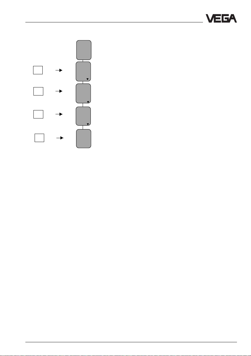
OK key (4)
With the OK key, adjustments can be confirmed.
When the symbol
move with the OK key to the next lower menu
level.
When the symbol appears, there is no
branching below the menu item, but only
another menu item belonging to the same
function.
ESC key (3)
With the Escape key (ESC) you can, depending on the menu item, interrupt an adjustment or a function or change to the next
higher menu level.
E.g. to reach the top menu level, push the
ESC key several times.
3
ESC
+
OK
4
▼
▼ or is displayed, you can
▼
▼
▼
+ and - key (2)
With the keys + and - you can modify the
values of the parameters or choose from
several options.
After pushing the first time, the values to be
adjusted flash. The value will be modified with
each additional push of the key.
30 Capacitive electrodes EL - Profibus PA

Setup
Arrow keys (5)
With the keys > and <, you can move within
the menu level from one menu item to the
other.
Digital indication (1)
On the digital indication, the actual measured
value is displayed during operation. When
you adjust the instrument, the clear text indication displays the appropriate function.
▼
Branching point from which you can
change to a lower menu.
▼
This symbol informs you about an ensuing
▼
safety enquiry.
Adjustment steps
On the following pages, you will find the menu
schematic of the adjustment module
MINICOM.
Set up the sensor in the following sequence.
The numbers correspond to the setup sequence. You will find the numbers near the
appropriate menu items in the menu schematic on the following pages.
1. Sensor optimisation
2. Adjustment
3. Conditioning
4.Outputs
1. Sensor optimisation
With this function, you can set the sensor
optimisation suitable for your application. With
it, the phase angle of the phase selective
admittance processing (PSA) is modified.
"Mode 1" is preset.
Mode 1 = Standard (90°)
The standard setting is recommended for
unproblematic applications such as e.g.
liquids with small DK values or with electrodes in conjunction with a concentric tube.
The standard setting is also recommended
for non-conductive vessels with an exterior
grounding surface.
Mode 1 is a pure capacitance measurement,
the ohmic conductance is not taken into account in the measuring result.
Application:
- standard setting
- non-conductive liquids up to approx. 50 µS
- compensation of conductance changes in
liquids
- generally with partly insulated electrodes in
liquids
- non-conductive solids without moisture
content
- with insufficient product grounding
- with electrodes in conjunction with a concentric tube
- in non-conductive vessels with exterior
grounding surface
Mode 2 = PSA (45°)
For buildup, varying product moisture content
With this mode, the patented phase selective
admittance processing (PSA) is set. This
setting is recommended for problematic
applications in solids, mainly if fluctuations of
the moisture content occur, and in conductive
liquids that stick to the electrode.
The capacitance and the ohmic conductance
are measured separately, the capacitance
value is corrected by calculating it with the
ohmic conductance, so that measurement
errors caused by conductive buildup or
varying product moisture content are compensated.
Capacitive electrodes EL - Profibus PA 31

Setup
Application:
- highly conductive products
- adhesive, conductive products
- solids with fluctuating moisture content
For use in conductive, viscous liquids, a
suitable electrode of type EL 24 or EL 24
should be used.
2. Adjustment
Under the menu item "
the sensor of the meas. span it should operate in.
Max.
Min.
You can carry out the adjustment with medium or without. Generally, you will carry out
the adjustment with medium, because the
electrode can then adapt to the conditions in
the vessel.
Adjustment
100 % corresponds to 1200 l
0 % corresponds to 456 l
", you inform
Span
The following criteria apply to the conductivity:
Mode 1 (90°) Mode 2 (PSA 45°)
with conc. tube > 50 µS/cm > 150 µS/cm
w.o conc. tube > 100 µS/cm > 300 µS/cm
Adjustment in
First of all, choose the unit you want to carry
out the adjustment in. Possible are pF, m or ft.
Offset correction
Carry out the offset correction with
unimmersed electrode.
This is necessary in order to save the initial
capacitance in the electronics. The electrode
must be mounted in the vessel and it must be
completely uncovered by the medium.
For electrodes with concentric tube, this
function is already carried out at VEGA, as
the vessel does not influence the measurement. The offset correction must only be
repeated if the oscillator is exchanged.
Conductivity
If you have selected adjustment in m or ft,
you have to enter whether the medium is
conductive or non-conductive. If the medium
is non-conductive, you also have to enter the
dielectric constant in the next menu item.
The above table shows you the criteria that
Adjustment without medium
apply to conductivity in capacitive measure-
ment.
If you want to carry out the adjustment without medium, your measurement loop must
meet certain requirements.
In conductive medium
- electrode is fully insulated
Adjustment with medium
Fill the vessel e.g. to 10 %, enter in the menu
"
Min. adjustment
" with the "+" and "–" keys 10
% and confirm with the "OK" key. Then fill the
In non-conductive medium
- concentric tube electrode
- you know the DK value of the medium
vessel e.g. to 80 % or 100 %, enter in the
menu "
Max. adjustment
" with the "+" and "–"
keys 80 % or 100 % and confirm with the
"OK" key.
32 Capacitive electrodes EL - Profibus PA
Setup
Key Display
Sensor
m(d)
4.700
Para-
OK
OK
OK
OK
meter
adjustment
Adjustment
with
medium
Min.
adjust
at %
-------
(Min. adjustment)
3. Conditioning
Under the menu item "
can scale the display, set an integration time
and choose a linearisation curve.
Scaling
Here, you can scale the digital display of the
electrode.
Signal conditioning
" you
If you need for the max. possible value a
number with more than four digits, then you
should choose the next higher unit, e.g.
14000 l = 140 hl.
Decimal point
If necessary, set the position of the decimal
point. Keep in mind that max. 4 digits can be
displayed.
Unit
In the menu "
unit (%, t, ft
yd, m
Unit
", you choose the physical
3
, in3, gal, in, lb, pF, m, cm, mm, ft,
3
, kg, l, hl).
Linearisation curve
In the menu "
Lin. curve
", you can choose
between three standard linearisation curves.
Preadjusted is a linear depedency between
percentage value of the level and the percentage value of the filling volume.
You can choose between linear, cylindrical
tank, spherical tank and user-programmable
linearisation curve. Programming your own
linearisation curve is only possible with the
PC and the adjustment program VVO. A
user-programmable curve, however, can be
transferred from the PC to the electronics of
the instrument and called up under this menu
item.
0 % correspond
Here, you enter the value which should be
displayed when 0 % level is reached, e.g.
20 l.
100 % correspond
Here, you enter the value which should be
displayed when 100 % level is reached, e.g.
1200 l.
Integration time
In the menu item "
Integration time
", you can
set a delay (in seconds) for the signal output.
4. Outputs
Under the menu "
display and determine which parameter
should be outputted by the sensor display
Outputs
", you can scale the
and the PA output.
Capacitive electrodes EL - Profibus PA 33

Menu schematic of the adjustment module MINICOM
1.
Parameter
Sensor
optimize
Mode 1
Configuration
Add’l
functions
Info
Sensor
Tag
Sensor
type
CAP
E34
Serial
number
Softw.
vers.
Sensor
addr.
max.
range
Setup
1)
Offset
Capac-
pF
itance
pF
pF/m
Adjustment
with
medium
Min.
adjust
at %
XXX.X
2.
Max.
adjust
at %
XXX.X
Sensor
Tag
w.out
medium
Adjustment
in
Elec-
Sensor
trode
addr.
type
No. 01
3.
Signal
conditioning
Lin.
Scaling
0 %
corres
ponds
XXXX
1)
2)
Offset
Medium
conductive
DK
value
(Er)
correction
pF
Electrode
uncovered?
Offset
pF
Now!
OK?
0 %
100 %
at
at
pF
curve
Linear
100 %
corres
ponds
XXXX
pF
Integr
ation
time
Decimal
point
888.8
0 s
Unit
%
Menu items only available with:
1)
Adjustment in m or ft
2)
Non-conductive medium
3)
Concentric tube or double rod electrode
34 Capacitive electrodes EL - Profibus PA

Setup
Outputs
4.
Simulation
Reset
Reset
to default
Reset
to default
OK
Reset
Now!
OK ?
Total
reset
Total
reset
OK?
Reset
Now!
OK ?
Language
English
DK
measurement
Immersion
DK
meas.
Now!
OK?
DK
value
(Er)
3)
3)
3)
3)
PA
output
Failure
prop.
mode
to
Error
Vol u -
value
me
With these keys you move in
the menu field to the left, to the
right, top and bottom.
Sensor
display
prop.
to
Percent
ESC
OK
Simulation
Now!
Simulation
in V%
XXX.X
OK?
act.
dist.
m
X,XX
Fast
change
Yes
Bolt print figures are sensor or
measured value information and
cannot be modified in this position.
The menu items in white letters
stand for figures which can be
modified with the "+" or "–" key
and saved with the "OK" key.
Capacitive electrodes EL - Profibus PA 35

Setup
4.3 Adjustment with VVO
If the oscillator CAP E34 PA Ex is installed,
the electrode can also be adjusted via a PC
with the adjustment software VVO (from version 2.60).
Before the sensors can be operated and
adjusted with the adjustment program VVO
(VEGA Visual Operating) via Profibus PA,
they must be integrated into the Profibus
system. Address the sensors first (chapter
4.1 Adjustment media) and then connect
them to the PA segment. With the attached
GSD file (instrument master file), you then
integrate the sensors into your system. The
GSD file can be integrated by means of an
appropriate tool, e.g. Siematic Manager, into
your system.
To connect the PC to the DP bus, a standard
RS 485-DTE interface cable (Data Terminal
equipment) is necessary. With the cable, you
connect the DP interface card with the bus or
with the segment coupler.
PCPC
PC
PCPC
Screen 1 1 Screen
– – 2 2 M24
RxD/TxD-PRxD/TxD-P
RxD/TxD-P
RxD/TxD-PRxD/TxD-P
33
3
33
– – 4 4 CNTR-P
GNDGND
GND
GNDGND
55
5
55
– – 6 6 VP
– – 7 7 P24
RxD/TxD-NRxD/TxD-N
RxD/TxD-N
RxD/TxD-NRxD/TxD-N
88
8
88
– – 9 9 CNTR-P
Profibus-DP DP-Bus (in brackets
interface card the PIN number of the P+F
BUSBUS
BUS
BUSBUS
33
RxD/TxD-PRxD/TxD-P
3
RxD/TxD-P (40)
33
RxD/TxD-PRxD/TxD-P
55
GNDGND
5
GND (55)
55
GNDGND
88
RxD/TxD-NRxD/TxD-N
8
RxD/TxD-N (41)
88
RxD/TxD-NRxD/TxD-N
segment couplers)
VVO connection to the b us cable
You need a Profibus DP interface card (from
Softing) in your PC in order to adjust the
sensor with the adjustment software VVO.
This card must be used to make the connection between computer and Profibus DP
cable (a direct connection or a connection to
the Profibus PA cable is not possible). With it,
the computer with VVO has the status "Master class 2".
Segment
coupler
DP cable
VVO
Profibus DP
interface card
(Softing)
Sensor Sensor Sensor Sensor
VEGACONNECT 3
If the computer is connected to the Profibus
DP cable or via VEGACONNECT 3, you can
start VVO. When connecting via VEGACONNECT 3, you need VVO version 2.80 or
higher.
Profibus PA
cable
36 Capacitive electrodes EL - Profibus PA

Setup
• Switch on the power supply of the connected sensor.
• Start the adjustment software VVO (VEGA
Visual Operating) on your PC.
• In the entrance screen, you choose with
the arrow keys or the mouse the item
ning
and click to OK. You should only
choose
Planning
if you are authorised to
Plan-
modify the instrument parameters. Otherwise choose
Operator
or
Maintenance
. In
the window "User identification", you are
asked for the name and the password.
• For setup (
name:
VEGA
Planning
VEGA
) you enter under
and under password also:
. It does not matter if you use capital
or small letters.
VVO recognises automatically the type of the
connected sensor and immediately afterwards indicates with which sensor a connection exists.
The following adjustment steps are described in their sequence and should be
carried out in the same order during the initial
setup.
For further information, see the operating
instruction manual of the adjustment program
VEGA Visual Operating (VVO).
First of all, click to "Profibus DP (for PA sensors". Then choose the Profibus card which
is installed in your PC and click to OK. Then
restart VVO. If you are connected via a
VEGACONNECT 3, choose the option
Standard.
For a connection via VEGACONNECT 3, you
need VVO version 2.80 or higher.
Sensor configuration
If you start VVO as described above, i.e. if
you have connection to the Profibus, you will
see the following presentation on your
screen. Click to Configuration, then to
Measuring system.
If you do not get a connection to the instrument, click to Configuration, choose Pro-
gram and click to Communication .
If you have already connected several VEGA
sensors to the bus, you select the sensor
you want to configure - in this case the capacitive electrode. The serial number and the
bus address of the sensor will be displayed
to ensure a clear identification. Through
VEGACONNECT 3 you can access only one
sensor.
Configuration
Display Diagnostics Instrument data Configuration Services Quit Help
Capacitive electrodes EL - Profibus PA 37
system
Measuring
Measurement loop >
Program >
Language
User access
Communication

Setup
Under the menu item "Configuration", you can
choose the following functions:
• Measuring system
• Measurement loop
•Program
The electrode is already preset at VEGA. The
measuring system must only be configured if
the oscillator is exchanged.
Measuring system
In this window, you can choose the respective electrode. You can find the electrode
type on the type plate of the instrument.
Choose the correct electrode from the list,
e.g. EL 21: 14 mm PTFE. In front of the listed
electrodes you see the electrode type
number. The number belonging to your capacitive electrode is stated on the type plate
(see also chapter "1.6 Type plate"). If your
electrode is not included in the list, choose
´not configured´
confirm the setting.
. Push the Save button to
Profibus PA address
In this window, you can assign a bus address to the sensor in the field "Sensor address". This function is only available if the
mini coding switch on the oscillator is set to
>126.
Reset
In this menu window, you can carry out two
different resets.
Standard reset (reset to default)
Adjustment 0 % - 0 pF
100 % - 3000 pF
Adjustment unit pF
Integration time 0 s
Linearisation linear
Sensor display scaled
Scaling 0.0 % 100 %
PA output volume
Failure mode last value
Sensor optimisationMode 1 (90°)
Total reset
With a total reset, all adjustments which can
be carried out via VVO or MINICOM are
reset.
This includes, e.g., the following data:
- electrode type
- Tag name
- offset correction
A total reset is necessary, e.g. if the oscillators are installed on another electrode.
Information on the sensor ident number:
You do not have to modify the setting "VEGA
specific No.". Only if you want to make sure
the sensor can be replaced on the Profibus
by a sensor from another manufacturer do
you have to choose the option "Profile specific No.".
38 Capacitive electrodes EL - Profibus PA

Setup
Configuration of measurement loops
Click to Configuration, point to Measurement loop, then click to Modify.
Now all instruments connected on the bus
are listed (identifiable by means of bus address and serial number). Choose the sensor (the measurement loop) you want to use
to create a measurement loop and click to
OK.
Measurement loop description
In this field, you can give your measurement
loop a descriptive label, e.g. level - cleaning
detergent. Up to 80 characters can be entered. The measurement loop description is
not saved in the sensor, but in the PC.
Application
For capacitive electrodes,
ment
is permanently set and cannot be modi-
fied.
Program
In this menu item, you can modify settings of
the program.
Level measure-
Language
Here you can change the program language.
With OK you reach again the window "VEGA
Modify measurement loop configuration
In this window, you can more clearly specify
your measurement loop.
Measurement loop no. (Sensor-TAG)
In this field, you can enter a measurement
loop number, e.g. tank 15/3. Max. 16 characters are available.
Capacitive electrodes EL - Profibus PA 39
Visual Operating".
User access
With this function, you can modify the user
name and the password or deactivate the
password enquiry.
Communication
Here you can determine the settings for data
transmission.

Options
In this function, program settings such as
backup, etc., are available.
Instrument data
Display Diagnostics Instrument data Configuration Services Quit Help
Under the menu item "Instrument data", you
can choose the function:
• Parameter adjustment.
Parameter adjustment
Setup
From the window "Instrument data parameter
adjustment", you can reach all submenus of
the sensor. Just test the various buttons one
after the other. You will always return to this
window. Click to the button Adjustment to
carry out the adjustment.
There you find the following functions:
- Adjustment
- Conditioning
- Outputs
- Sensor optimisation
- Additional functions
Sensor parameter adjustment
Click to Instrument data, then to Parameter
adjustment.
Adjustment - Min/Max. adjustment
With this function, you can adjust the capacitive electrode (Min/Max. adjustment). You can
choose if you want to carry out the adjustment with or without medium.
In the windows "Min. adjustment" and "Max.
adjustment" (with medium) as well as "Min/
Max. adjustment" (without medium) it is possible to enter an offset in percent. By doing
this, the initial value is shifted by the entered
Choose the measurement loop on which you
want to carry out the parameter adjustment
and click to OK.
40 Capacitive electrodes EL - Profibus PA
percentage value. A modification of this offset
is normally not necessary.

Setup
Note! Do not confuse this offset with the
offset correction (Instrument data/Parameter
adjustment/Additional functions).
Adjustment with medium
Min. adjustment
There must be min. level in the vessel. If you
push the button
entered percentage value.
For example, if you know that your vessel is
filled to 10 %, this can be entered under min.
adjustment.
Max. adjustment
There must be max. level in the vessel. If you
push the button
entered percentage value. You can also
assign a certain percentage value to a known
level.
For example, if you know that your vessel is
filled to 90 %, this can be entered under max.
adjustment.
Adjustment without medium (dry adjustment)
Save
, the output is set to the
Save
, the output is set to the
Under certain circumstances, an adjustment
can also be carried out without medium with
the help of the processing software VVO.
The requirements for an adjustment in m are:
In conductive medium:
- electrode is fully insulated
The following criteria apply to the conductivity:
Mode 1 (90°) Mode 2 (45°)
w. conc. tube > 50 µS/cm >150 µS/cm
w.o.conc.tube >100 µS/cm >300 µS/cm
In non-conductive medium:
- concentric tube electrode
- you know the DK value of the medium
If you already know the electrode capacitance of another similar measurement loop
(same electrode, same installation conditions,
same medium), you can also carry out a dry
adjustment in pF.
With an unimmersed electrode, first carry out
an offset correction (only for adjustment in m:
Instrument data - Parameter adjustment Additional functions
Adjustment without medium
You can choose if you want to carry out the
adjustment in pF or in m. If you have chosen
adjustment in m, you have to enter whether
your medium is conductive or non-conductive. If the medium is non-conductive, you
also have to enter the DK value.
The above table shows you the conductivity
criteria applicable to capacitive measurement
and whether you have to choose
or
Non-conductive
). Go again to the function
.
Conductive
.
If you have chosen m, you can assign a
corresponding value in m to the percentage
value.
Example
0 % = 0.2 m
100 % = 3.2 m
Capacitive electrodes EL - Profibus PA 41

If you have chosen pF, you can assign a
corresponding value in Picofarad to the percentage value.
Example
0 % = 97.2 pF
100 % = 1428.0 pF
The values for the adjustment will be accepted by pushing the button
OK
.
Conditioning
The following functions are available in this
window:
- Scaling
- Linearisation
- Integration time
Setup
Click in the window "Conditioning" to
Linearisation.
Scaling
With this button, a message appears telling
you that for Profibus sensors, this function
can be found in the menu window "
data parameter adjustment
item "
Output
". Carry out the scaling there.
" under the menu
Instrument
With oscillator CAP E34 PA Ex you can also
enter your own linearisation curve for special
vessels, e.g. cylindrical vessel with large
funnel-shaped outlet, under "user-programmable curve".
Push the button
Edit.
You can enter the value
pairs (percentage value - volume value) for
Linearisation
32 index markers.
In this window, you can linearise non-linear
vessels, such as e.g. a cylindrical tank. The
following linearisation curves are available:
- linear
- cylindrical tank
- spherical tank
- user-programmable curve
Click in the window "Instrument data parameter adjustment" to Conditioning.
42 Capacitive electrodes EL - Profibus PA

Setup
Push the button
linearisation curves.
In the window "Linearisation", you can choose
the linearisation curves of a horizontal cylindrical tank or a spherical tank. If you choose
a user-programmable curve, you can then
click to Edit and open the program "Tank
Calculation". With this program, you can calculate the curves of different tank forms (see
the manual "VEGA Visual Operating"). After
the selection of the curve, click to OK.
Transfer
, to call up further
Sensor parameter adjustment – Integration time
Choose this function if you want to set an
integration time (damping).
The range for the integration time is between
0 and 600 seconds. As a standard feature,
an integration time of zero seconds is preset.
After the set integration time has expired,
63 % of the measured value change remain
on the output.
In the window "Instrument data parameter
adjustment", you click to Conditioning.
Click in the window "Conditioning" to Integra-
tion time.
In the window "Integration time" you can enter
a time of max. 600 seconds. Then click to
OK.
Sensor parameter adjustment – Outputs
In this window, you can change the preset
values for the PA output and the measured
value display. Push the button
fer the modified values.
Save
to trans-
Click in the window "Instrument data parameter adjustment" to Outputs.
Capacitive electrodes EL - Profibus PA 43

Setup
Click in the window "Outputs" to Profibus
output.
In the window "Profibus output" you can determine the options for Profibus output (acc.
to Profibus PA instrument profile). Confirm the
settings with OK. The values under
change the Profibus output and the value on
any display that may be connected. To use
the values for a display, "scaled" must be
chosen under "Display of measured value".
"Scaling"
Sensor parameter adjustment – Sensor
optimisation
In this window, the mode of the sensor can
be set. With this, you modify the phase angle
of the phase selective admittance processing
(PSA). "Mode 1" is preset.
Mode 1 = Phase angle 90°
Mode 1 is a pure capacitance measurement,
the ohmic resistance is not taken into account
in the measuring result.
Application:
- standard adjustment
- non-conductive liquids up to approx. 50 µS
- compensation of conductance changes in
liquids
- generally with partly insulated electrodes in
liquids
- non-conductive solids without moisture
content
- with insufficient product grounding
- for electrodes in conjunction with a concentric tube
- in non-conductive vessels with exterior
grounding plate outside
Mode 2 = Phase angle 45°
The capacitance and the ohmic conductance
are measured separately, the capacitance
value is corrected by calculating it with the
ohmic conductance, so that measuring errors
caused by conductive buildup or changes of
moisture content can be compensated.
Application:
- highly conductive products
- adhesive, conductive products
- solids with fluctuating moisture content
When clicking "Display of measured value",
you can choose twhat should be displayed
on the sensor display, e.g. level, capacitance
or scaled value.
44 Capacitive electrodes EL - Profibus PA
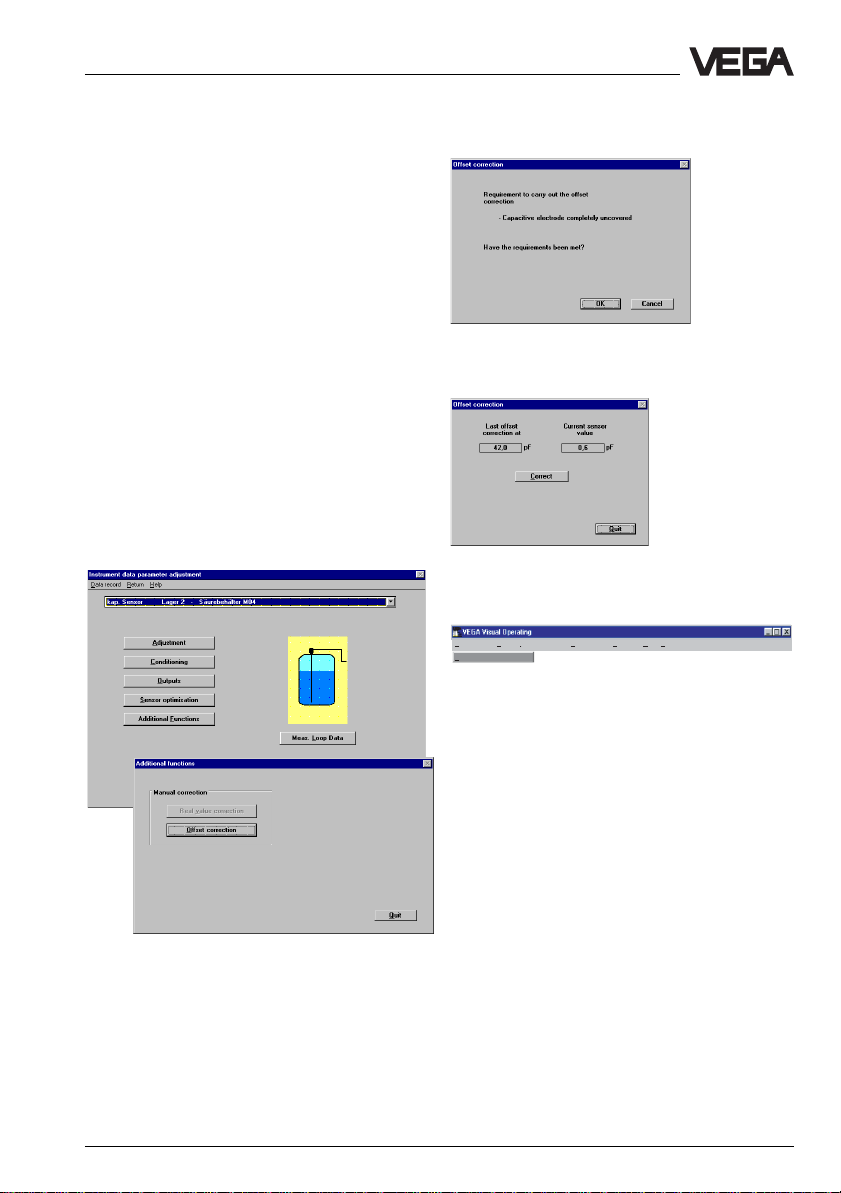
Setup
Sensor parameter adjustment – Offset
correction
This function is necessary if an adjustment
should be carried out in m. With this function,
the initial capacitance is saved in the electronics. A prerequisite is that the electrode is
installed in the vessel and completely
unimmersed.
An offset correction is only necessary if adjustment without medium is to be carried out.
For electrodes with concentric tube, this
function is already carried out by VEGA,
since the vessel does not influence the measurement. The offset correction must only be
repeated of the oscillator is exchanged.
Click in the window "Instrument data parameter adjustment" to Additional functions,
then in the window "Additional functions" to
Offset correction.
Confirm the question with OK, if the conditions are met.
Click in the window "Offset correction" to
Correct.
Display
Display Diagnostics Instrument data Configuration Services Quit Help
Display of measured value
Under the menu item "Display", you can
choose the function:
• Display of measured value.
Display of measured value
In this window, the actual measured value is
displayed digitally and as bar graph.
The upper bar shows the current measured
value in percent, pF or scaled in the set unit.
The actual values of the measurement loops
can be displayed from the main menu. Click
to "Display" and then to "Display of measured
value".
Capacitive electrodes EL - Profibus PA 45

Choose the requested measurement loop
and click to OK.
In the window "Display of measured value"
you can choose the unit in which the measured value should be displayed. By clicking
to Quit you return to the window "VEGA
Visual Operating".
Setup
Diagnostics
Display Diagnostics Instrument data Configuration Services Quit Help
Status
Si
mulation
Under the menu item "Diagnostics" you can
choose the following functions.
• Status
• Simulation
Status
This function is not available.
Simulation
With this function, you can simulate a certain
level. Push the start button to activate the
simulation. Shift the scrollbar to the request
PA output value or enter a specific PA output
value. The scaled display bar will be modified
accordingly.
To interrupt the simulation, push the button
Stop
.
The simulation will be stopped automatically if
you close the window
To check the outputs of the electrodes and
connected instruments or components, you
have to click to Diagnostics, then to Simula-
tion.
Simulation
.
46 Capacitive electrodes EL - Profibus PA

Setup
Select the requested measurement loop and
click to OK.
In the window "Simulation of outputs", you
click to Start, to start the simulation. With the
buttons "<–" and "–>" (or with the slide switch)
you can set values between -10 % and
110 %. To quit the simulation, click to Stop.
Under the menu item "Services", you can
select the following functions:
• Print
•View
• Backup
• Restore configuration
• Edit database
• User level
• Connection
• Modem
Print
With this function, you can print a list of all
sensor settings.
View
With this function, you can display on screen
the list of sensor settings.
Backup - Sensors
In this window, you can save the settings of
the sensor in a database.
Restore configuration - Sensors
In this window, you can call up the sensor
settings from the database.
Note:
The simulation mode will not be stopped
automatically, it remains active until you
Edit database
In this window, you can edit the saved sensor
data in the database.
switch it off!
User level
Services
Display Diagnostics Instrument data Configuration Services Quit Help
Capacitive electrodes EL - Profibus PA 47
Print
View
Backup >
Restore configuration >
Edit database
User level
Connection F8
Modem F7
Signal conditioning
Sensors
instruments
In this window, you can select the user levels.
The following user levels are available.
- Operator
- Maintenance
- Planning

Operator
This user level is for the operator. In this
level, you can have the measured value
displayed and the sensor data printed.
There is no password required for this
level.
Maintenance
If you select the level Maintenance, all functions are available except configuration.
The password for this level is: VEGA.
Planning
If you select the level Planning, all functions
are accessible. The passwords for the
planning level are: VEGA - VEGA.
Connection
With this function you can restart connection
set-up. This function can also be activated
with the key F8.
Modem
This window enables adjustments for data
transfer via modem. This function can also be
activated with the key F7. The modem does
not have to meet special requirements.
Setup
Bits & Bytes
In this window, you can call up the current
measured values of all connected sensors
with the function "Display of measured value".
The function Live-List shows all data of the
connected sensors.
48 Capacitive electrodes EL - Profibus PA

Diagnosis
5 Diagnostics
5.1 Simulation
To simulate a certain filling level, you can call
up the function Simulation in the oscillator or in
the adjustment program VVO. You hereby
simulate a certain PA output value. Remember that connected instruments, such as e.g.
a PLC, react according to their settings and
that alarms may be triggered or system
functions activated.
5.2 Maintenance
The instrument is maintenance-free.
5.3 Repair
Repair work requires opening the instrument
to correct defects. For safety and warranty
reasons, all internal work on the instruments,
apart from that involved in normal installation
and connection, must be carried out only by
qualified VEGA personnel.
In case of a defect, please return the affected
instrument with a short description of the
error to our repair department.
Failures are short-term malfunctions of the
instrument which are caused by wrong adjustment or defects in the sensor or the connection cables.
Failures, their possible causes and their
rectification are stated under "5.4 Failure
rectification".
Capacitive electrodes EL - Profibus PA 49

Diagnosis
5.4 Failure rectification
Failure Measure, failure rectification
Sensor defective, Test the internal connections:
measurement does • Loosen the 4 screws of the housing cover with a Phillips screwdriver
not react to level
changes • Loosen the two small screws with a Phillips screwdriver and pull the
no display of oscillator out of the housing.
measured values
and remove the housing cover.
• Measure with an ohmmeter (range MOhm) the resistance values
between the following contacts:
6
CM
1 MΩ
CM - Capacitor
Screen
3
4
Contact 4 and middle pin (1)
The resistance must be 1 MOhm.
If the resistance is less, it indicates moisture in the housing or a defect
in the electrode insulation. A possible reason could be a non-insulated
electrode used in a conductive (moist) medium.
If the resistance is higher or if the connection is interrupted, the reason
is usually a bonding failure in the adapter plate or a resistor defective
due to strong electrostatic discharge.
In both cases, return the sensor to VEGA for repair.
50 Capacitive electrodes EL - Profibus PA

Diagnosis
Fail ure Measure, failure rectification
Contact 4 and vessel
The connection between contact 4 and the metal vessel (not instrument
hexagon or electrode flange) should be as good as possible. Measure
with an ohmmeter (range very low) the resistance value between contact 4 and the vessel.
• Short-circuit (0 … 3 Ohm, optimum connection)
• Resistance > 3 Ohm
- corrosion on the mounting thread or flange
- possibly the mounting thread was covered with Teflon tape or a
similar material
Check the connection to the vessel. If there is no connection, you can
connect a cable from the external grounding terminal to the vessel.
Make sure that coated flanges are always connected via the grounding
terminal to the vessel.
Contact 4 and 6
Values > 3 Ohms indicate a defect.
If you cannot find a failure in the sensor, then replace the oscillator with
a similar type (if available) or send the sensor for repair to VEGA.
After replacement of the electronics, a fresh adjustment must be carried
out (see "4 Setup").
Error message Invalid measured value
Invalid measured The current measured value is outside the valid measuring range.
value E030 Causes can be e.g. considerable changes of the DK value or
PA status 81, 82 incorrect settings.
Change the current measuring conditions.
Error message Instrument error
Instrument error An error in the sensor was found.
E068
PA status 16, 68, 72 Possible causes are:
- supply voltage not within tolerance
- defective oscillator
- damage to the electrode or to the insulation
- electrode short-circuited against vessel wall
• Separate the sensor from power supply and then reconnect (cold
start).
• If the error message does not extinguish, check the sensor cable
and the correct power supply.
• If the error message does not extinguish, check the sensor for vis-
ible damage.
If you cannot find any faults, please call our service department.
Capacitive electrodes EL - Profibus PA 51

Fail ure Measure, failure rectification
Error messageError message
Error message Increase the span between empty and full adjustment.
Error messageError message
Adjustment span
too small
E017
Error messageError message
Error message Instrument error
Error messageError message
General An error in the sensor was found.
instrument error
E034 Possible causes are :
PA status 12 - supply voltage not within tolerance
- defective oscillator
- damage to the electrode or to the insulation
- electrode short-circuited against vessel wall
• Separate the sensor from power supply and then reconnect (cold
start).
• If the error message does not extinguish, check the sensor cable
and the power supply (correct voltage).
• If the error message does not extinguish, check the sensor for visible damage.
If you cannot find any faults, please call our service department.
Notes
52 Capacitive electrodes EL - Profibus PA

Notes
Capacitive electrodes EL - Profibus PA 53

Notes
54 Capacitive electrodes EL - Profibus PA

Notes
Capacitive electrodes EL - Profibus PA 55

VEGA Grieshaber KG
Am Hohenstein 113
D-77761 Schiltach
Phone (07836) 50-0
Fax (07836) 50-201
E-Mail info@de.vega.com
www.vega.com
ISO 9001
All statements relating to scope of delivery, application, practical use
and operating conditions of the sensors and processing systems
correspond to the latest information at the time of printing.
Technical data subject to alterations
2.25 712 / August 2001
 Loading...