

Page 1
Operating Instruction
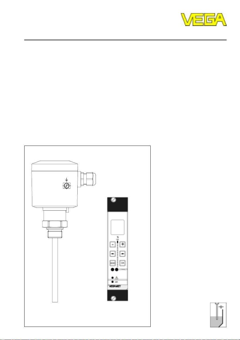
Capacitive electrodes EK …
with signal conditioning instrument
Level and Pressure
Page 2

Safety information
Safety information
The described module must only be installed
and operated as described in this operating
instruction. Please note that other action can
cause damage for which VEGA does not take
responsibility.
2 Capacitive electrodes EK with signal conditioning instrument
Note Ex-area
Please note the attached approval documents
(yellow binder) and especially the included
safety data sheet.
Page 3

Contents
Contents
Safety information ........................................................................ 2
Note Ex-area ................................................................................ 2
1 Product description
1.1 Function and configuration .................................................. 4
1.2 Types and versions ............................................................. 6
1.3 Technical data ....................................................................... 8
1.4 Approvals ........................................................................... 14
1.5 Dimensions ......................................................................... 15
1.6 Type plate ........................................................................... 17
2 Mounting
2.1 Mounting instructions ......................................................... 18
3 Electrical connection
3.1 Connection instructions ..................................................... 23
3.2 Wiring plan .......................................................................... 24
4 Set-up
4.1 General adjustment ........................................................... 27
4.2 Level detection ................................................................... 28
4.3 Continuous level measurement ......................................... 29
5 Diagnosis
5.1 Simulation ............................................................................ 31
5.2 Maintenance ....................................................................... 31
5.3 Repair .................................................................................. 31
5.4 Failure removal ................................................................... 32
Capacitive electrodes EK with signal conditioning instrument 3
Page 4
1 Product description
1.1 Function and configuration
Capacitive electrodes series EK detect levels
of virtually any medium, unaffected whether
liquids, powders, granules or pastes. This is
also valid for adhesive mediums.
The electrode measures also the level capacitance and the ohmic resistance (admittance processing). Hence also problematic
mediums and solids with fluctuating humidity
contents can be detected.
By the use of screening tubes and screen
segments, inactive areas can be provided on
the probe where pollution, condensation or
permanent build-up do not influence the
measuring result.
Measuring principle
Electrode, medium and vessel wall form an
electrical capacitor.
Product description
Electrode and vessel wall are the capacitor
plates. The medium is the dielectricum. Due
to the higher dielectric constant figure (DKvalue) of the medium against air, the capacitance of the capacitor increases with raising
covering of the electrode.
Fig. 1.2 Capacitance change with covered
electrode
The capacitance of the capacitor is mainly
influenced by three factors:
- distance of the electrode plates (a)
- size of the electrode plates (b)
The capacitance change is converted by the
oscillator into a level proportional, floating
current in the range of 4 … 20 mA or into a
switching command.
- kind of dielectricum between the electrodes (c)
Continuous level measurement
With the continuous level measurement, the
appropriate level is continuously detected
and converted into a level proportional signal
which is either directly indicated or further
b
c
Fig. 1.1 Plate capacitor (schematic demonstration)
4 Capacitive electrodes EK with signal conditioning instrument
processed.
You require a capacitive electrode series EK
with oscillator and a signal conditioning instrument VEGAMET, converting the proportional current of the oscillator into
standardised current and voltage signals.
The continuous measurement requires a
constant dielectric constant figure er, i.e. if
possible the medium should have steady
features.
Page 5

Product description
The floating signal of the electrode electronics
is in the range 4 … 20 mA and can be therefore connected without additional potential
separation to other processing systems such
as e.g. VEGALOG.
In addition to the continuous measurement,
also levels can be detected (VEGAMET or
VEGAMET + VEGASEL).
Level detection
Level switches should signal when certain
levels are reached, e.g. max. or min. levels.
These levels are detected at a fixed point
and converted into a switching command.
For level detection capacitive electrodes EK
with appropriate signal conditioning instruments VEGATOR are available. A switching
command can be either triggered when the
electrode is covered or uncovered.
Capacitive electrodes EK with signal conditioning instrument 5
Page 6
Product description
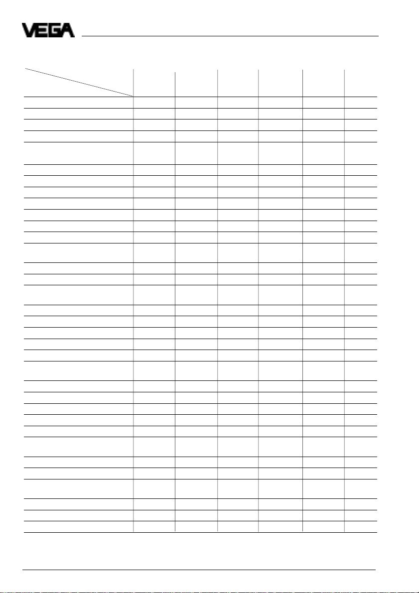
1.2 Types and versions
*)
Type
Version 11 21 24 26 31 42
Continuous • • • • •
Level detection • • • • • •
Partly insulated • •
Fully insulated • • • •
Oscillators
E 14 • • • •
E 15 • • • •
E 15 Ex • • • •
E 17 • • • •
E 17 Ex • • • •
E 18 ••••••
E 18 Ex • • • • • •
Approvals
CENELEC EEx ia IIC T6 • • • • • •
PTB-Zone 0 EEx ia IIC T6 • • • • • •
Overfill protection
acc. to WHG • • • • • •
German Lloyd
Lloyds Register of Shipping
American Bureau of Shipping
Bureau Veritas
RINA
1)
1)
1)
1)
1)
EK EK EK EK EK EK
• •••••
• •••••
• •••••
• •••••
• •••••
Mechanical connection
G 3/4 A • •••••
G 1 A • • • • • •
3/4" NPT • • • • • •
1“ NPT • • • • • •
Flange plated • •
Electrode material
Steel • •
StSt •
Isolating material
5)
2)
2)
•
3)
•
4)
•
3)
•
PTFE • • • •
FEP • •
PE • • •
6 Capacitive electrodes EK with signal conditioning instrument
Page 7
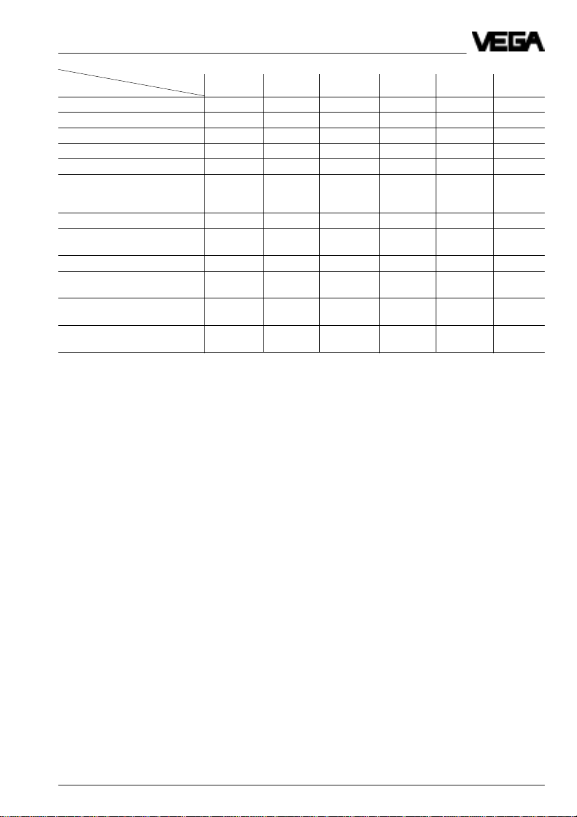
Product description
*)
Version 11 21 24 26 31 42
Type
Concentric tube
StSt • •
Screening tube (option)
StSt • • • • •
Temperature adapter
(option)
StSt • • • •
Housing material
Plastic (IP 66) • • • • • •
Aluminium - plastic coated
(IP 66 and 67) • • • • • •
Others
Bending of
electrode
6)
*) All instrument types also Ex0
1) applied
2) 1.4435
3) 1.4571
4) 1.4401
5) For electrodes certified for Ex-Zone 0, only PTFE and FEP are approved as isolating material.
6) Bending max. 90°
7) EK 21 only with PTFE with 3,2 mm isolation thickness
EK EK EK EK EK EK
••
7)
Capacitive electrodes EK with signal conditioning instrument 7
Page 8

Product description
1.3 Technical data
Housing
Housing material plastic PBT (Polyester) or Aluminium
Protection
- plastic housing IP 66
- Aluminium housing IP 66 and 67 (meets both protections)
Cable entry 1 pce. M20 x 1,5
Terminals for max. 1,5 mm2 cross-section area of
Mechanical connection
Material 1.4435 (316 L)
Thread G 3/4 A or 3/4“ NPT
Flange flange versions, plated
Electrode
Material EK 11 1.4435 (316 L)
Length
- rod max. 3 m
- cable max. 20 m
Isolation see "Isolating materials"
Max. tensile strength
- EK 31 3 KN
- EK 42 3 KN
plastic coated
conductor
G 1 A or 1“ NPT
EK 21 steel (St 37), 1.4435 (316 L)
EK 31 1.4401 (316 L)
EK 24, 42 1.4571 (316 L)
Ambient conditions
Ambient temperature on the housing -40°C … +80°C
Medium temperature see "Product temperature and operating
Storage and transport temperature -40°C … +80°C
Operating pressure see "Product temperature and operating
Oscillators E14, E15, E17, E18
Protection class II
Overvoltage category III
Meas. frequency see table on the following page
Capacitance ranges see table on the following page
Supply voltage 12 … 36 V DC (powered by signal conditioning
Potential separation min. 500 V DC (except E14)
8 Capacitive electrodes EK with signal conditioning instrument
pressure"
pressure"
instrument)
Page 9
Product description
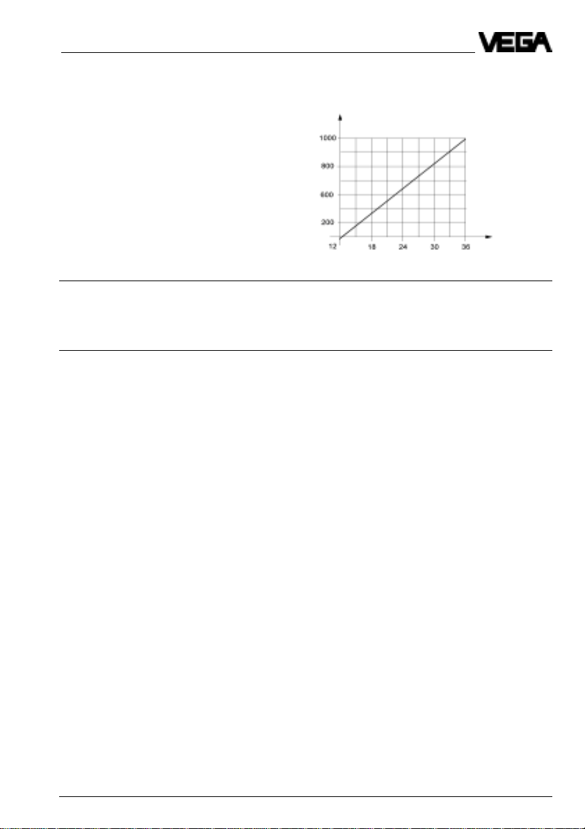
For Ex-applications note the permissible
electrical connection values stated in the
certificate.
Load in W
Accessory
Straining spring of 1.4571 (EK 42, EK 52, EK 53)
- load approx. 185 mm (stressed)
- tensile load approx. 200 N
Weight
Basic weight (e.g. EK 24) approx. 0,8 kg
Rod weight ø 6 mm - 0,23 kg/m
ø 10 mm - 0,62 kg/m
Cable weight (EK 31) approx. 40 g/m
Supply
voltage in V
Capacitive electrodes EK with signal conditioning instrument 9
Page 10

Product description
Oscillators in two-wire technology for capacitive electrodes EK
Typ e Application Meas. range Frequency Signal cond.instr.
E14 Level detection in general I: 0 … 25 pF 400 kHz VEGATOR
E15 Level detection in general I: 0 … 25 pF 400 kHz VEGATOR
with potential separation II: 0 … 100 pF VEGALOG
E15 Ex as E15, however for use in I: 0 … 25 pF 400 kHz VEGATOR Ex
hazardous areas acc. to II: 0 … 100 pF VEGALOG
CENELEC, PTB zone 0 as well as III: 0 … 400 pF
zone 1 and StEx zone 10 and as
part of an overfill protection acc. to
WHG, (VbF)
E17 Continuous level measurement in I: 0 … 120 pF 40 kHz VEGAMET
general or level detection with II: 0 … 600 pF VEGALOG
potential separation III: 0 … 3000 pF (VEGATOR)
E17 Ex as E17, however for use in I: 0 … 120 pF 40 kHz VEGAMET Ex
hazardous areas acc. to II: 0 … 600 pF VEGALOG
CENELEC, PTB zone 0 as well as III: 0 … 3000 pF (VEGATOR Ex)
zone 1 and StEx zone 10 and as
part of an overfill protection acc. to
WHG, (VbF)
2)
E18
Continuous level measurement I: 0 … 120 pF 470 kHz VEGAMET
or level detection with potential II: 0 … 600 pF VEGALOG
separation acc. to the principle of III: 0 … 3000 pF (VEGATOR)
phase selective admittance processing especially for adhesive mediums
and for the use in solids with
varying humidity
2)
E18 Ex
as E18, however for the use in I: 0 … 120 pF 470 kHz VEGAMET Ex
hazardous areas acc. to II: 0 … 600 pF VEGALOG
CENELEC, PTB zone 0 as well as III: 0 … 3000 pF (VEGATOR Ex)
zone 1 and StEx zone 10 and as
part of an overfill protection acc. to
WHG, (VbF)
1)
with safety barrier
2)
see following page
II: 0 … 100 pF VEGALOG
III: 0 … 400 pF
III: 0 … 400 pF
1)
1)
1)
10 Capacitive electrodes EK with signal conditioning instrument
Page 11
Product description
Oscillator E18
The oscillator E18 with the patented processing (phase selective admittance processing)
extends the application range of capacitive
level measurement technology.
In conjunction with the fully insulated rod
electrode EK 24 the oscillator E18 compensates even very conductive build-up.
Mounted in an individual rod or cable electrode type EK, E18 ensures also the exact
measurement in solids with varying humidity
contents.
The oscillator E18 processes the measuring
currents according to their phase position.
Measuring current with a defined phase
shifting as they occur with build-up or humidity changes are filtered out.
Humidity change
A humidity change in solids causes a change
of the dielectric constant figure (er). In parallel
the ohmic value of the medium changes. Due
to the change also a phase shifting of the
measuring currents is caused.
Level
measured value
+
1)
–
0 %
5 %
10 %
1) Actual value level
Fig. 1.3 Humidity change
15 % vol.
fully insulated
electrode
Solid
humidity (%)
partly insulated electrode
With a capacitive measurement already lowest humidity changes cause measuring errors. Typical products are e.g. sand,
aggregate in the cement industry, hop or
plastic granules (after drying).
When using the oscillator E18 humidity
changes of 15 % vol. do not influence the
accuracy of the measurement. Even layering
of product with different humidity does not
play a role for the measuring accuracy.
When the humidity contents exceeds 15 %
vol., fully and partly insulated electrodes
react differently (see also "Fig. 1.3 Humidity
change“). Whereby the measured value on
fully insulated electrodes raises with steady
level, the measured value on partly insulated
electrodes drops.
Capacitive electrodes EK with signal conditioning instrument 11
Page 12

Product description
Product temperature and operating
pressure
1)
The figures in the tables relate to the pictures
on this page. The statements on pressure
are valid for screw connections G 3/4 A,
3
/4“NPT, G 1 A, 1“NPT.
With flange versions you have to note their
nominal pressure.
All electrodes are also suitable for vacuum
(-1 bar).
For electrodes certified for Ex-Zone 0 only
PTFE and FEP are approved as isolating
material acc. to ATEX II 1/2 G EEx ia II C T6.
Mechanical connection, 1.4435 (316 L)
Isolation
Electrode type
EK 11 1 3 -
EK 21 1 3 -
EK 21 with flange - 2 -
EK 24 - - 2
EK 26 - 3 -
EK 26 with flange - 2 -
EK 31 1 3 -
EK 42 - 2 -
PE
PTFE
FEP
bar
40
0–50 100
bar
40
25
0–50 100
EK 21 to 16 bar
EK 42:
to 16 bar
EK 24:
from 100°C 6 bar,
max. 150°C for
30 mins.
°C
Temperature
adapter
1
2
3
200 °C
1) For Ex-applications the permissible temperatures and pressures stated in the certificate should be noted.
Additionally note the table on the following page.
12 Capacitive electrodes EK with signal conditioning instrument
Page 13

Product description
Electronics temperature
The following product and ambient temperatures must be maintained so that the limit
temperature on the electronics is not exceeded.
The stated values are obligatory for
applications in hazardous areas. Note
for these applications also the appropriate legal documents (test reports, test
certificates, type approvals and conformity
certificates).
Temperature class T6
Product temperature -40°C … +60°C
Ambient temperature -40°C … +60°C
Temperature class T5
Product temperature -40°C … +75°C
Ambient temperature -40°C … +75°C
Temperature classes T4 … T1 (or no Ex)
Without temperature adapter
- product temperature -40°C … +100°C
- ambient temperature -40°C … +80°C
With temperature adapter
Plastic housing Metal housing
Product temperature -40°C … 180°C 200°C 150°C 175°C 200°C
Ambient temperature
1) Ambient temperature on the oscillator
Capacitive electrodes EK with signal conditioning instrument 13
1)
-40°C … 80°C 75°C 80°C 69°C 58°C
Page 14

Product description
1.4 Approvals
Explosion protection
Only certified capacitive electrodes EK**Ex 0
must be used in hazardous areas with combustible gases, vapours or fog.
Capacitive electrodes EK**Ex 0 are suitable
for the use in hazardous areas of zone 1 and
zone 0. Proof for the explosion protection of
these instruments is the EC-type approval
and the conformity certificate possibly with
national zone 0 - annex. These documents
are generally attached to the instrument.
When the capacitive electrodes are mounted
or operated in hazardous areas, the Exinstallation regulations must be noted.
The information and regulations of the supplied certificates (EC-type approval, conformity certificate) of the capacitive
electrodes as well as of the appropriate instrument (signal conditioning instrument,
separator, safety barrier) must be noted.
• The mounting of Ex-systems must be generally carried out by skilled staff.
• The capacitive electrodes must be powered by an intrinsically safe circuit; the
permissible electrical values are stated in
the appropriate certificate.
• Capacitive electrodes with electrostatically
chargeable plastic parts are provided with
a warning label informing about measures
which must be taken to avoid dangers
caused by electrostatic discharges. Note
the contents of the warning label.
• The explosion protection of the instrument
used is only ensured when the limit temperatures stated in the certificate are not
exceeded.
ˇ In case of danger due to oscillation or
vibration, the appropriate parts of the capacitive electrodes must be secured.
• After shortening of the electrode cable, it
must be noted that the weight is sufficiently
secured by means of pins.
WHG
The electrodes EK … Ex0 are also approved
as part of an overfill protection for vessels
storing water endangering liquids.
Ship approvals
For the use on ships, type approval certificates are available of several ship classification authorities (GL, LRS, ABS, BV, RINA).
For electrodes certified for Ex-Zone 0, only
PTFE and FEP are permitted as isolating
materials acc. to ATEX II 1/2 G EEx ia IIC T6.
CE-approval
The capacitive electrodes EK meet the protective regulations of EMVG (89/336/EWG)
and NSR (72/23/EWG). The conformity has
been judged acc. to the following standards:
EMVG Emission EN 50 081 - 1
Susceptibility EN 50 082 - 2
NSR EN 61 010 - 1
Zone 2
According to DIN VDE 0165, instruments can
be used in hazardous areas of zone 2 without approval; they must meet the requirements in section 6.3 of this VDE. The
compliance of the instruments with these
requirements is confirmed by Messrs. VEGA
in a manufacturer declaration.
14 Capacitive electrodes EK with signal conditioning instrument
Page 15

Product description
1.5 Dimensions
Dimensions of the capacitive electrodes type EK
Type EK 11 (partly insulated)
32,5
85
EK 11 with concentric tube
85
32,5
Type EK 21 (fully insulated)
85
32,5
M20x1,5
SW 41
G 3/4 A
A
B
L (min. 100 mm, max. 3000 mm)
EK 21 with concentric tube
85
32,5
M20x1,5
SW 41
G 3/4 A
M20x1,5
SW 41
G 3/4 A
ø21,3
Type EK 24 (fully insulated,
for adhesive products)
85
32,5
M20x1,5
SW 41
G 3/4 A
M20x1,5
SW 41
G 3/4 A
A
L (min. 100 mm, max. 3000 mm)
Type EK 26
32,5
85
M20x1,5
SW 41
G 3/4 A
ø21,3
L (min. 100 mm, max. 3000 mm)
Isolation A B
PE 2 ,0 mm 14 mm 10 mm
PTFE 2,0 mm 10 mm 6 mm
PTFE 2,0 mm 1 4 mm 10 mm
outer-ø rod-ø
ø14,4
L (min. 120 mm, max. 3000 mm)
ø14
Capacitive electrodes EK with signal conditioning instrument 15
Page 16

Type EK 31 (partly insulated)
SW 41
G 3/4 A
L (min. 400 mm, max. 20000 mm)
Housing
Product description
Housing of plastic / Aluminium
Temperature adapter
SW 41
SW 41
of galvanized steel or 1.4571
Concentric tube
of 1.4435
ø21,3
Screening tube
ø21,3
of 1.4435 with closing
cone of PP or PTFE
Closing cone
16 Capacitive electrodes EK with signal conditioning instrument
Page 17

Product description
1.6 Type plate
Before mounting and electrical connection
please check if you use the suitable instrument. Therefore note the type plate which is
located as follows:
Type plate
The type plate contains important data required for mounting and connection. The
configuration and components of the type
plate are hence explained in the following
example.
Configuration of the type plate (example)
VEGA® EK 11
1
type EK11EXO.XGBVSTXXVKXX
see PTB no. EX-98.E.2085 EEx ia IIC T6 0032
2
PTB 98 ATEX 2086 II 1/2G EEx ia IIC T6
3
techn. data see document. / certificates 1998
protection: IP 66/67 Insp.
length: 400mm VVO: 02
4
Ord. no. 123456/000
®
D-77757 Schiltach
5
Z-65.13.XXX
7
1 Master data of the order no.
2 Ex-certification number
Explosion protection version - note the
information and regulations of the certificate
3 Data of the electronics / Approvals
4 No. of the order confirmation/Pos.-no.
5 Number of the electrode type
6 Serial number
7 Test mark when used as part of an overfill
protection for vessels storing water endan-
gering liquids - note the information and
regulations of the general type approval
8 Manufacturing year
9 Number of the test authority
9
8
6
Order code
Detailed information on the order code you
will find in the "Product Information Capacitive“ or in the "VEGA-Pricelist“.
Capacitive electrodes EK with signal conditioning instrument 17
Page 18

2 Mounting
Mounting
2.1 Mounting instructions
General
Different mediums and requirements to the
measurement require various installations.
Hence the following instructions should be
noted.
Length of the level electrode
Note when ordering the electrode, that the
electrode must be sufficiently covered according to the electrical features of the medium (DK-value).
E.g. an electrode for level detection in oil
er ~ 2) requires a considerably higher covering than in water (er ~ 81).
Lateral load
Note that the electrode is not subjected to
strong lateral forces. Mount the electrode in a
position in the vessel where no interfering
influences such as e.g. stirrers, filling opening etc. occur. This is mainly valid for very
long rod and cable electrodes.
Extraction forces
In case of strong extraction forces e.g. during filling or settling of solids, high tensile
loads can be caused.
In these cases use for short measuring distances a rod electrode, as a rod is generally
more stable. If due to the length or the mounting position a cable electrode should be
necessary, the electrode should not be
strained, but only equipped with a gravity
weight as then the cable can more easily
follow the product movements. Note that the
electrode cable does not touch the vessel
wall.
Pressure
In case of gauge or low pressure in the vessel, the mounting boss must be sealed at the
thread. Use the attached seal ring. Check if
the seal ring is resistant against the medium.
Isolating measures such as e.g. the covering
of the thread with Teflon tape can interrupt the
electrical connection in case of metal vessels.
Hence earth the electrode on the vessel.
Fig. 2.1 Lateral load
18 Capacitive electrodes EK with signal conditioning instrument
Page 19

Mounting
Shortening of the electrode
The dimensions of fully insulated electrodes
are fixed and must not be modified. Each
modification will destroy the instrument.
Partly insulated cable or rod electrodes can
be shortened afterwards. Note that due to
the change of the basic capacitance also the
switch point can change.
When the cable should be considerably
shortened, it can happen that an adjustment
of the electrode is not possible. A new compensation of the electrode will be necessary
in this case. Note the serial number of the
electrode and call one of our sales engineers.
The electrode is compensated to the appropriate electrode length. For this reason you
should already state in the order if you want
to shorten the electrode.
Cable electrode EK 31 can be shortened
afterwards (see fig. 2.2). Loosen the two pins
on the gravity weight (hexagon) and remove
the two pins. Pull the cable out of the gravity
weight.
To avoid splicing of the steel cable (EK 31)
during cutting, you have to tin the cable
around the cutting position with a copper bit
or strongly tighten the cable with a wire.
Shorten the electrode cable with a metal
cutting saw or a cutting-off wheel by the
requested length.
Carry out the adjustment. The instruction is
under "4.1 Adjustment“.
Fig. 2.2 Shortening of the electrode
Filling opening
Install the electrode such that it does not
protrude directly into the filling stream.
Should such an installation place be necessary, mount a suitable sheet above or in front
of the electrode e.g. L 80 x 8 DIN 1028, etc.
Fig. 2.3
Horizontal installation
The electrodes can be mounted horizontally
to reach a very exact switch point with level
detection. We recommend to mount the electrode approx. 20° inclined to the bottom, so
that build-up can be avoided.
Fig. 2.3
a.
b.
20°
Sheet
Fig. 2.3 Horizontal installation
Capacitive electrodes EK with signal conditioning instrument 19
Page 20

Mounting
Humidity from outside
After installation turn the cable entries of
horizontally mounted instruments to the bottom to avoid humidity ingress. The instrument
housing is rotational by approx. 330°. In case
of vertically installed electrodes, loop the
connection line to the electrode housing to the
bottom so that rain or condensation water
can drain off.
This is mainly valid for mounting outside, in
areas where humidity must be expected
(e.g. by cleaning processes) or on cooled or
heated vessels (see fig. 2.4).
Fig. 2.4 Humidity
Cable entries
When mounting outside, on cooled vessels or
in humid areas where cleaning is made e.g.
with steam or high pressure, the sealing of
the cable entry is very important.
Use cable with a round cross-section area of
conductor and tighten the cable entry. The
cable entry is suitable for cable diameters of
5 mm to 9 mm.
Aluminium vessels
Use for Aluminium vessels an electrode with
steel thread. The combination Aluminium on
Aluminium should be avoided, as the thread
"seizes“ when being screwed and cannot be
loosened after some time without being damaged.
Metal vessels
Note that the mechanical connection of the
electrode is electrically conductive connected
with the vessel to ensure sufficient earth.
Use conductive seals such as e.g. copper,
lead etc. Isolating measures such as covering the thread with Teflon tape can interrupt
the necessary electrical connection. In this
case use the earth terminal on the housing to
connect the electrode to the vessel wall.
Non-conductive vessels
In non-conductive vessels, e.g. plastic tanks,
the second pole of the capacitor must be
provided separately, e.g. by a concentric
tube or the use of a double rod electrode.
When using a standard electrode, a suitable
earth plate is necessary. Hence provide a
possibly large earth plate, e.g. wire braiding
laminated into the vessel wall or metal foil
which is glued to the vessel. Connect the
earth plate with the earth terminal on the
housing.
Rod electrode
Mount the electrode such that the electrode
protrudes into the vessel. When mounting in
a tube or a socket, build-up can be caused
which can influence the measurement. This is
particularly the case with viscous or adhesive
products.
(see fig. 2.5)
20 Capacitive electrodes EK with signal conditioning instrument
Page 21

Mounting
max. 80 mm
Lateral installation
With electrodes, delivering continuous measured values, the electrode must only be installed vertically. Should the installation from
top not be possible, the electrodes can also
be mounted laterally (see fig. 2.7)
If there are struts or a roof at the installation
place of the electrode, you should check if a
rod electrode of the requested length can be
mounted. If a mounting of the rod electrode is
not possible, use a cable electrode.
Fig. 2.5 Rod electrodes
Cable electrodes in solids
Dependent on the kind of solid and position
or kind of filling, the cable electrode can
"float“ despite of the gravity weight. The electrode (cable) is pushed by the solid to the
vessel wall or to the top and wrong measured values are caused. This should be
avoided with the continuous level measurement.
In this case use a fixing weight to fasten the
electrode.
When fixing the cable electrode avoid high
tensile strengths. An appropriate fixing
spring avoiding overloading of the cable is
listed in our pricelist as accessory (see fig.
2.6)
Under the accessory in our pricelist you find
a screening tube and a closing cone or a
bent rod electrode by which the electrode
can be also mounted laterally. Choose the
length (l) of the screening tube such that no
product bridges can be caused between
cable and vessel wall and that the electrode
cable cannot touch the vessel wall due to
product movements. Use a fixing weight or a
fixing insulator.
Fixing weight
Fig. 2.7 Continuous electrodes
Fig. 2.6 Cable electrode in solids
Capacitive electrodes EK with signal conditioning instrument 21
Page 22

Mounting
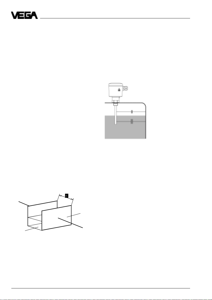
Material cone
Note when installing the electrodes into the
vessel, that material cones can be caused
with solids which can change the switch
point. We recommend to choose an installation place where the electrode detects an
According to the position of the filling and
emptying opening in the vessel, the electrode
must be installed appropriately. To compensate the measuring errors caused by the
material cone, you should install the electrode
at a distance of d/6 from the vessel wall.
average value of the material cone.
Filling
Fig. 2.8 Material cone, filling and emptying centered
Filling Emptying
Emptying
3
2
1 Emptying
2 Filling opening
Fig. 2.9 Material cone, filling centered, emptying laterally
22 Capacitive electrodes EK with signal conditioning instrument
3 Capacitive
electrode
1
Page 23

Electrical connection
3 Electrical connection
3.1 Connection instructions
Note
Switch off the power supply before starting
connection work.
The electrical connection must be made dependent on the installed oscillator. The installed electronics type is stated on the type
plate of the oscillator. Connect the supply
voltage according to the following connection
diagrams.
Note
If strong electromagnetic interferences have
to be expected, we recommend to use
screened cable. The screening of the cable
should only be earthed at one sensor end
(electrode).
Generally connect the electrode with vessel
ground (PA). For this purpose there is a
terminal laterally on the housing. This connection is additionally for the mass reference
potential as well as to drain off electrostatic
charges.
Skilled staff
Instruments operated in Ex-areas must only
be mounted by skilled staff. They must note
the mounting regulations and the supplied
EC-type approvals and conformity certificates.
When capacitive electrodes are mounted on
vessels which must be protected according
to TRbF 100 no. 8, para.1 against inflammation due to lightning, they have to be
equipped with the external overvoltage arrester type B 62-36 G or the internal overvoltage protection unit type CB 2-36.
Capacitive electrodes EK with signal conditioning instrument 23
Page 24

3.2 Wiring plan
The electrical connection of the sensor to the
signal conditioning instrument is stated in the
operating instruction of the appropriate signal
conditioning instrument.
Note
The oscillator is independent of the electrode
and can be exchanged locally.
As the oscillators have different characteristics (approx. 5 %), it can be necessary to
readjust the signal conditioning instrument
after electronics exchange.
Electrical connection
0/4 … 20 mA
DISBUS
24 Capacitive electrodes EK with signal conditioning instrument
Page 25

Electrical connection
Capacitive electrode with external overvoltage protection unit
Vessel without cathodic corrosion protection
Ex-area
Electrode EK
optionally overvoltage arrester
B62 - 36 G Ex 0 (metal housing) or
B62 - 36 G Ex (plastic housing)
(Li = 0,15 mH, Ci = 1,5 nF)
Outer
isolation
1
2
B
E1
A1
Typ
E2
A2
B62-36G
Screen
Outer
isolation
Screen
Not-Ex-area
(control room)
optionally overvoltage arrester
A
E1
Typ
B62-36G
Signal conditioning
instrument or safety
barrier
A1
A2E2
min. 4 mm2 Cu
Vessel
Zone 0
External earth terminal
to potential euqalization line
Earth/ PA-connection
terminal
Note:
[A] Between control room and overvoltage protection system a suitable cable, if necessary a metal cover or
screen, should be used. Screen or metal cover - if necessary - must only be connected to the electrode
side of the overvoltage arrester.
[B] Between overvoltage protection system and capacitive electrode a suitable cable with metal cover, screen
or a suitable cable with metal protection tube should be used (screen, metal cover or protection tube must
be connected to the potential equalisation).
Test voltage of the cable A and B: £ 500 V AC
Capacitive electrodes EK with signal conditioning instrument 25
Page 26

Vessel with cathodic corrosion protection
Ex-area
Electrode EK
External
earth
terminal
optionally overvoltage arrester
B62 - 36 G Ex 0 (metal housing) or
B62 - 36 G Ex (plastic housing)
(Li = 0,15 mH, Ci = 1,5 nF)
Outer
B A
isolation
A1 A1
2
A2
B62-36G
Typ
Metal housing
mounted earth-free
E1
E2
Screen
min. 4 mm2 Cu
Vessel
Zone 0
Earth / PA-connection
terminal
Note:
[A] and [B] see "Vessel without cathodic corrosion protection“ on
Cathodic corrosion protection
2 … 24 V (object voltage)
the previous page.
Outer
isolation
Screen
Not-Ex-area
(control room)
optionally overvoltage arrester
E11
Typ
B62-36G
Capacitive electrode with integral overvoltage protection module
Vessel with/without cathodic corrosion protection
Electrical connection
Signal conditioning
instrument or safety
barrier
A2E2
Ex-area
Not-Ex-area
(control room)
optionally overvoltage arrester
B62-36G
A1
Typ
A2E2
Signal conditioning
instrument or safety
barrier
Note:
Electrode EK
[1]
1
2
Vessel
Zone 0
Outer
A
isolation
E1
Screen
[A] Between control room and overvoltage
protection system a suitable cable, if
External
earth
terminal
Without cathodic corrosion protection: to
potential equalisation line
Cathodic corrosion protection
2 … 24 V (object voltage)
necessary with screen or metal cover, should
be used. Connect screen or metal cover - if
necessary - only to the electrode side of the
overvoltage protection system. With cathodic
corrosion protection the cable must be
provided with an outer isolation.
26 Capacitive electrodes EK with signal conditioning instrument
Page 27

Set-up
4 Set-up
4.1 General adjustment
When you state with your order already the
medium to be measured, the electrode will be
adjusted by VEGA. The DK-value and the
conductivity of the medium as well as the
length of the electrode will be considered.
For the set-up the electrode must be adjusted with the original medium.
For adjustment of the electrode, the housing
cover must be opened. With the changeover
switch on the oscillator you can choose the
sensitivity range of the electrode.
E14, E15 E17, E18
Stage I 0…25 pF 0…120 pF
(sensitive)
Stage II (standard) 0…100 pF 0…600 pF
Stage III (less
sensitive) 0…400 pF 0…3000 pF
The instruction for adjustment or switch point
adjustment is stated in the operating instruction of the appropriate signal conditioning
instrument.
Capacitive electrodes EK with signal conditioning instrument 27
Page 28

Set-up
4.2 Level detection
Vertically installed electrodes
• Set the changeover switch on the oscillator
of the electrode to stage I.
• Choose the requested mode (A - overfill
protection, B - dry run protection) on the
signal conditioning instrument.
• Fill the vessel to the requested level.
• Carry out the adjustment. Turn the potentiometer on the signal conditioning instrument (VEGATOR) very slowly until the
signal lamp changes condition.
Should the adjusted measuring range not
be sufficient to find the switch point, you
have to set the changeover switch to the
next higher stage (II or III). Note also the
switch point adjustment of the signal conditioning instrument.
Horizontally installed electrodes
• Set the changeover switch on the oscillator
of the electrode to the appropriate stage.
Note the following conditions:
EK with E14, E15
- non-conductive medium range 1
- conductive medium to 0,25 m range 2
to 0,25 m range 3
- EK 26 with E18 range 1
If there is no other information, the oscillators E14, E15 and E18 are preadjusted to
range 1.
• Choose the requested mode (A - overfill
protection, B - dry run protection) on the
signal conditioning instrument.
• Make sure that the integration time is
switched off (see operating instruction of
the signal conditioning instrument).
• Empty the vessel or lower the level at least
up to 100 mm below the electrode.
• Carry out the empty adjustment. Therefore
turn the potentiometer on the signal conditioning instrument (VEGATOR) very slowly
clockwise until the relay control lamp lights
(mode A) or extinguishes (mode B).
- when the potentiometer on the signal
conditioning instrument is above the
value 7, you should set the changeover
switch to range 2.
• Note the position of the potentiometer.
• Fill the vessel until the electrode is completely covered.
• Carry out the full adjustment. Turn the potentiometer on the signal conditioning instrument (VEGATOR) very slowly
clockwise until the relay control lamp lights
(mode A) or extinguishes (mode B).
• Note the position of the potentiometer.
• Set the potentiometer to the average value
of the two noted values.
28 Capacitive electrodes EK with signal conditioning instrument
Page 29

Set-up
4.3 Continuous level measurement
When you state the medium with your order, the oscillator of the electrode is already preadjusted. In this case the medium is stated on the order confirmation.
• Choose with the changeover switch on the oscillator the stage according to the following
schedule.
Take the column corresponding to your medium and choose by means of the length of your
electrode the suitable range.
The stated lengths partly do not correspond to the actually available electrodes.
When the medium has a DK-value which is between the values stated in the table, the max.
permissible electrode length per measuring range must be averaged appropriately.
In case of larger lengths or when there is nothing else stated in the table, choose range 3.
If you are not sure, set the changeover switch always to the next higher stage.
Medium Non-conductive Non-conductive Conductive
EK-type and DK = 2 and DK = 10 or DK > 50
EK 11 0 - 5,5 m range 1 0 - 0,8 m range 1 ––
EK 11 with concentric tube 0 - 1,5 m range 1 0 - 0,15 m range 1 ––
EK 18 0 - 6 m range 1 0 - 1 m range 1 ––
EK 21 (2 mm-isolation) 0 - 5 m range 1 0 - 1,1 m range 1 0 - 0,25 m range 1
EK 21 (2 mm-isolation) 0 - 2 m range 1 0 - 0,5 m range 1 0 - 0,3 m range 1
with concentric tube – – 0,5 - 2,5 m range 2 0,3 - 1,7 m range 2
EK 21 (3,2 mm-isolation) 0 - 6 m range 1 0 - 1,5 m range 1 0 - 0,6 m range 1
EK 21 (3,2 mm-isolation) 0 - 3,5 m range 1 0 - 1 m range 1 0 - 0, m range 1
with concentric tube – – 1 - 5,5 m range 2 0,7 - 4 m range 2
EK 24 0 - 6 m range 1 0 - 1 m range 1 0 - 0,15 m range 1
EK 24 with concentric tube 0 - 2 m range 1 0 - 0,4 m range 1 0 - 0,15 m range 1
EK 26 0 - 6 m range 1 0 - 1,5 m range 1 0 - 0,5 m range 1
EK 31 0 - 6 m range 1 0 - 1 m range 1 ––
EK 42 0 - 9 m range 1 0 - 2 m range 1 0 - 0,8 m range 1
1)
Oscillator E17 from a conductivity > 10 µS, oscillator E18 from a conductivity > 100 µS.
–– 0,8 - 4,5 m range 2 ––
–– 0,15 - 0,9 m range 2 ––
–– 1 - 5,5 m range 2 – –
–– 1,1 - 6 m range 2 0,25 - 1,4 m range 2
–– 1,5 - 6 m range 2 0,6 - 3 m range 2
–– 1 - 5,5 m range 2 0,15 - 0,8 m range 2
–– 0,4 - 2 m range 2 0,15 - 0,9 m range 2
–– 1,5 - 6 m range 2 0,5 - 2,8 m range 2
6 - 30 m range 2 1 - 5 m range 2 – –
9 - 30 m range 2 2 - 10 m range 2 0,8 - 4,5 m range 2
1)
Capacitive electrodes EK with signal conditioning instrument 29
Page 30

Set-up
Signal conditioning instrument
VEGAMET series 300
When the electrode is not already preadjusted by VEGA, you have to choose the
measuring range.
• Set the changeover switch on the capacitive electrode EK according to the table on
the previous page.
• Turn the potentiometer for the full adjustment approx. 22 turns clockwise.
• Empty the vessel to the requested min.
level.
• Turn the potentiometer for the empty adjustment anticlockwise until the pointer of
the indicating instrument is at 0.
• Fill the vessel to the requested max. level.
The indication shows more than 100 %.
• Turn the potentiometer for the full adjustment anticlockwise until the pointer is at
100 %. When the indication cannot be set
to 100 %, proceed as follows:
- when the indication does not reach
100 %, you have to set the changeover
switch on the electrode one stage lower.
- when the indication exceeds 100 % and
cannot be reset, you have to set the
changeover switch to the next higher
stage.
In both cases you have to repeat the adjustment.
Signal conditioning instrument
VEGAMET 614, VEGAMET series 500
When the electrode is not already preadjusted by VEGA, you have to choose the
measuring range.
• Set the changeover switch on the capacitive electrode EK according to the table on
the previous page.
• Carry out the adjustment on the signal
conditioning instrument (see operating
instruction of the signal conditioning instrument: "Adjustment with medium“).
- when the signal conditioning instrument
displays the fault signal E014, this message is explained in the operating instruction of the signal conditioning
instrument under "Error code“. When
sensor and connection line work without
problems, probably a wrong range of
the capacitive electrode was chosen. Set
the changeover switch to the next higher
stage.
- When the signal conditioning instrument
displays the fault signal E017, set the
changeover switch on the electrode to
the next lower stage.
Signal conditioning instrument
VEGAMET series 600
(except VEGAMET 614)
When the electrode is not already preadjusted by VEGA, you have to choose the
measuring range.
• Set the changeover switch on the capacitive electrode EK according to the table on
the previous page.
• Carry out the adjustment according to the
operating instruction of the signal conditioning instrument (see operating instruction of the signal conditioning instrument
"Adjustment“).
When the indication cannot be set to 100 %
(10,0 V), proceed as follows:
- when the indication does not reach
100 % (10,0 V), you have to set the
changeover switch on the electrode to
the next lower stage.
- When the indication exceeds 100 %
(10,0 V) and cannot be reset, you have
to set the changeover switch of the electrode to the next higher stage.
In both cases you have to repeat the
adjustment.
30 Capacitive electrodes EK with signal conditioning instrument
Page 31

Diagnosis
5 Diagnosis
5.1 Simulation
Test switch
A test switch can be optionally integrated in
the housing to simulate a switching condition.
By pushing the test switch, an additional
capacitance is connected. Just the function
of the oscillator and the connected instruments are tested.
Note
When the changeover switch is set to position 3, it can be possible that the connected
capacitance is not sufficient to carry out a
test.
The test switch can be used to simulate a
max. level (overfill protection).
Test
Set the test switch to position 1. The
changeover of the test switch to position 1
increases the capacitance of the uncovered
electrode, so that the oscillator responds and
triggers a full signal. The connected instruments will be activated.
Note
It is absolutely necessary to reset the test
switch to basic position (position 0) after the
test.
5.3 Repair
Due to safety and guarantee reasons repair
work beside the wiring must only be made
by VEGA-staff.
In case of a defect, please return the appropriate instrument with a short description of
the error to our repair department.
Failures are short-term malfunctions of the
instrument which are caused by wrong adjustment or defect on the sensor or the connection lines.
Failures, possible reasons and their removal
are stated under "5.4 Failure removal“.
5.2 Maintenance
The instrument is maintenance free.
Capacitive electrodes EK with signal conditioning instrument 31
Page 32

5.4 Failure removal
Failure Measure, failure removal
The red failure- Check the sensor inputs on the following failures:
LED of the signal - short-circuit on the input
conditioning instru- - sensor not correctly connected
ment lights - sensor line interrupted
- supply voltage too low
Check if the sensor is connected correctly.
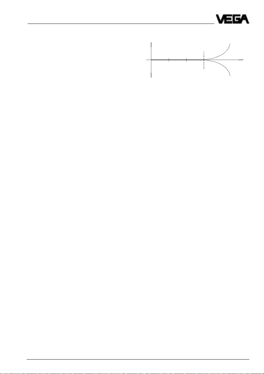
- failures on the sensor, effecting a current change below 2 mA or
above 23 mA, trigger a fault signal on the signal conditioning instruments.
Measure the current on the connection line to the sensor.
The terminal voltage of the sensor in standard condition is at least 12 V.
4 … 20 mA 12 … 24 V
mA
+
–
Sensor
V
28
+
30
–
32
Signal conditioning
instrument e.g.
VEGATOR
Diagnosis
Note with Ex-systems that the Ex-protection is not influenced
by the measuring instruments.
a. Current value < 2 mA
- Check the supply voltage on the connection line to the sensor. The
voltage should be approx. 17 … 24 V.
Should you measure a value below 17 V, the signal conditioning instrument is defect. In this case send the instrument to VEGA for
repair.
- Should the red failure lamp continue to light, separate the connection
line from the signal conditioning instrument and connect a resistor of
2,2 kOhm to the sensor inputs of the signal conditioning instrument.
Should the failure lamp continue to light, the signal conditioning instrument is defect. In this case return the instrument to VEGA for repair.
- Should the failure lamp extinguish, connect the signal conditioning
instrument again. Separate the sensor from the connection line and
connect instead a resistor of 2,2 kOhm.
- Should the failure lamp continue to light, perhaps the connection line
is interrupted. Check the connection line to the sensor.
- When the failure lamp extinguishes, the sensor is defect. Check the
connected sensor.
32 Capacitive electrodes EK with signal conditioning instrument
Page 33

Diagnosis
b.Current value > 22 mA
- Check all connections and the connection line to the sensor.
- Should the red failure lamp continue to light, separate the sensor from
the connection line and connect instead a resistor of 2,2 kOhm.
When the failure lamp extinguishes, the sensor is defect. Check the
connected sensor.
- Should the failure lamp continue to light, connect the sensor again.
Separate the signal conditioning instrument from the connection line
and connect a resistor of 2,2 kOhm to the sensor input.
- Should the failure lamp continue to light, the signal conditioning instrument is defect. In this case send the instrument to VEGA for repair.
- When the failure lamp extinguishes, this is perhaps a short-circuit in
the connection line. Check the connection line to the sensor.
Failure Measure, failure removal
Sensor defect, Test of the internal connections:
measurement does • Remove the housing cover.
not react to level • Loosen the three screws with a screwdriver and pull
changes the oscillator out of the housing. Use flat pliers to pull the
oscillator easily out of the housing. Hold the oscillator on the extension
of the separating wall between the sensor connections.
• Measure with an ohmmeter (range MW) the resistance values between the following contacts:
Screen
CM - Capacitor
Capacitive electrodes EK with signal conditioning instrument 33
Page 34

Diagnosis
Contact 4 against middle pin (1)
The resistor must be 1 MW.
If the resistor is less, this means humidity in the housing or a failure in
the electrode isolation. A possible reason could be a not isolated electrode used in a conductive (humid) medium.
If the resistor is higher or if the connection is interrupted, the reason is
mainly a bonding failure in the adapter plate or a defect resistor due to
strong electrostatic discharge.
In both cases return the electrode for repair to VEGA.
Contact 4 against vessel
The connection between contact 4 and the metal vessel (not instrument
hexagon or electrode flange) should be as good as possible. Measure
with an ohmmeter (range very low) the resistance value between contact 4 and the vessel.
• Short-circuit (0 … 3 W), optimum connection
• Resistance > 3 W
- corrosion on the mounting boss or flange
- probably the mounting boss was covered with Teflon tape or
similar
Check the connection to the vessel. If there is no connection, you can
connect a line from the earth terminal outside to the vessel.
Note that covered flanges must be in any case connected via the earth
terminal to the vessel.
Contact 7 against middle pin (1)
The resistor must be infinite (>10 MW).
If the resistor is less, humidity penetrated or the compensation capacitor is defect.
Contact 3 against 4
In case of electrodes without screen, the resistor is infinite (>10 MW).
With EK 26 the resistor should be 1 MW. In case of lower values, the
electrode isolation is defect or humidity penetrated into the instrument
housing.
In case of higher values there is a bonding failure in the adapter plate
or the resistor is defect.
Contact 4 against 6
With older sensors the resistor is infinite, with newer electrodes <3 W. In
case of values between 3 W and 10 MW there is a defect.
When you cannot find a failure in the electrode, then replace the oscillator by a similar type (if available) or send the electrode for repair to
VEGA.
If the failure disappears after insertion of the new replacement electronics, the adjustment on the signal conditioning instrument should be
repeated as the oscillators have different characteristics.
34 Capacitive electrodes EK with signal conditioning instrument
Page 35

Notes
Capacitive electrodes EK with signal conditioning instrument 35
Page 36

VEGA Grieshaber KG
Am Hohenstein 113
D-77761 Schiltach
Phone (0 78 36) 50 - 0
Fax (0 78 36) 50 - 201
e-mail info@vega-g.de
The statements on types, application, use and operating conditions of
the sensors and processing systems correspond to the actual
knowledge at the date of printing.
Technical data subject to alteration
2.22 647 / Nov. 98
 Loading...