

Page 1

HMP260 SERIES
TRANSMITTERS
Operating Manual
HMP260-U017en-1.5
5 January 1996
Vaisala 1996
Page 2

This page intentionally left blank.
Back of cover page.
Page 3

HMP260 SERIES
HMP260-U017en-1.5 Operating Manual
Contents
1. PRODUCT DESCRIPTION ......................................................................................... 1
2. TO BE NOTED WHEN M EASURING HUMIDITY........................................................ 3
3. INSTALLATION.......................................................................................................... 4
3.1. Selecting the place of installation ................................................................ 4
3.2. Mounting........................................................................................................ 5
3.2.1. HMP263 transmitter ......................................................................... 6
3.2.2. HMP264 transmitter ......................................................................... 7
3.2.3. HMP265 transmitter ....................................................................... 10
3.3. Grounding .................................................................................................... 11
3.4. Electrical connections................................................................................. 13
4. COMMISSIONING .................................................................................................... 15
4.1. Security lock jumper ................................................................................... 15
4.2. Selecting the analogue outputs .................................................................. 15
4.3. Connecting the RS 232C serial bus............................................................ 17
4.3.1. Reverting to factory settings of the serial port................................. 19
5. COMMANDS ............................................................................................................ 21
5.1. Commands and security lock jumper ......................................................... 21
5.2. LED commands ........................................................................................... 22
5.3. Display/keypad commands......................................................................... 23
5.3.1. Display mode ................................................................................. 23
5.3.2. Command m ode............................................................................. 23
5.3.3. Entering numbers........................................................................... 23
5.3.4. Analogue output commands ........................................................... 24
5.3.4.1. Selecting the output (mA/V)........................................................ 24
5.3.4.2. Selecting and scaling the analogue output quantities.................. 25
5.3.5. Output via the serial bus ................................................................. 26
5.3.5.1. Turning the serial interface echo ON/OFF................................... 26
5.3.5.2. Serial bus settings...................................................................... 26
5.3.5.3. Setting the transmitter address................................................... 27
5.3.5.4. Selecting the output units ........................................................... 27
5.3.6. Output modes................................................................................. 28
5.3.6.1. Setting the serial interface operation mode................................. 28
5.3.7. Others .......................................................................................... 29
5.3.7.1. Setting the measurement integration tim e................................... 29
5.3.7.2. Setting the pressure for m ixing ratio and wet bulb calc ulations ... 29
5.3.7.3. Setting the date .......................................................................... 30
5.3.7.4. Setting the time .......................................................................... 30
1997-11-25 i
Page 4

HMP260 SERIES
Operating Manual HMP260-U017en-1.5
5.4. Serial commands ......................................................................................... 32
5.4.1. Analogue output commands ............................................................ 32
5.4.1.1. Setting the analogue outputs ....................................................... 32
5.4.1.2. Selecting and scaling the analogue output quantities ..................33
5.4.1.3. Scaling the analogue outputs ......................................................33
5.4.2. Output via the serial bus .................................................................34
5.4.2.1. Starting the measurement output ................................................34
5.4.2.2. Stopping the measurement output ............................................... 34
5.4.2.3. Outputting the reading once........................................................ 34
5.4.2.4. Setting the output interval for the RUN mode ..............................35
5.4.2.5. Serial bus settings.......................................................................35
5.4.2.6. Selecting the output units............................................................36
5.4.2.7. Setting the transmitter address ...................................................36
5.4.2.8. Resetting the transmitter.............................................................36
5.4.4. Operating the transmitter via the serial bus.....................................36
5.4.4.1. Setting the serial interface...........................................................36
5.4.4.2. OPEN & CLOSE .........................................................................37
6. CALIBRATION..........................................................................................................38
6.1. Humidity calibration ....................................................................................38
6.1.1. One point humidity calibration.........................................................39
6.1.1.1 Using serial commands...............................................................39
6.1.1.2 Using display/keypad commands ................................................39
6.1.1.3 Using LED commands................................................................. 40
6.1.2. Two point humidity calibration.........................................................40
6.1.2.1 Using serial commands...............................................................40
6.1.2.2 Using display/keypad commands ................................................41
6.1.2.3 Using LED commands................................................................. 41
6.1.3. Calibration procedure after sensor c hange ...................................... 42
6.1.3.1 Using serial commands...............................................................42
6.1.3.2 Using display/keypad commands ................................................43
6.1.3.3 Using LED commands................................................................. 43
6.1.4. Humidity calibration table................................................................44
6.2. Temperature calibration .............................................................................. 44
6.2.1 One point offs et correction..............................................................45
6.2.2.1 Using serial commands...............................................................45
6.2.2.2 Using display/keypad commands ................................................45
6.2.2.3 Using LED commands................................................................. 46
6.2.2 Two point temperature c alibration...................................................46
6.2.2.1 Using serial commands...............................................................46
6.2.2.2 Using display/keypad commands ................................................47
6.2.2.3 Using LED commands................................................................. 47
6.3. Calibration of analogue outputs .................................................................48
6.3.1 Using serial com m ands ................................................................... 48
6.3.2 Using display/keypad commands ....................................................48
6.3.3 Using LED com m ands ....................................................................50
7. MAINTENANCE........................................................................................................50
7.1. Reference measurements............................................................................50
7.2. Self-diagnostics...........................................................................................50
7.3. Changing the HUMICAP® sensor and the filter.......................................... 51
7.4. Measurement of output currents using test points.................................... 51
7.5. Adjusting the contrast of the display..........................................................52
ii 1997-11-25
Page 5

HMP260 SERIES
HMP260-U017en-1.5 Operating Manual
8. TECHNICAL DATA................................................................................................... 53
8.1. Relative humidity......................................................................................... 53
8.2. Temperature................................................................................................. 53
8.3. Calculated variables.................................................................................... 53
8.4. Pressure ....................................................................................................... 55
8.5. Analogue outputs........................................................................................ 55
8.6. Electronics ................................................................................................... 55
8.7. Mechanics.................................................................................................... 56
8.8. Environmental conditions ........................................................................... 58
8.8.1 Emissions ....................................................................................... 58
8.8.2 Imm unity ........................................................................................ 58
9. OPTIONS ................................................................................................................. 59
10. SPARE PARTS......................................................................................................... 59
Appendix 1 Serial commands
Appendix 2 Safety summary
Appendix 3 Installing and using the RS 485/422 serial port module
Appendix 4 Installing and using the digital current loop module
Appendix 5 Error messages
Appendix 6 Calculation formulas: dewpoint, m ixing ratio and abs olute hum idity
Appendix 7 Wiring diagr am MK4462
Appendix 8 Installation diagram MK4461
Appendix 9 Approvals and specifications of the protection unit
Certificates: Technical Research Centre of Finland No. Ex-94.C.016X
No. Ex-94.C.018X
DEMKO No. 94C.115330X
This manual is f or progr am m e vers ion HMPS260 1.01
1997-11-25 iii
Page 6

HMP260 SERIES
Operating Manual HMP260-U017en-1.5
This page intentionally left blank.
iv 1997-11-25
Page 7

HMP260 SERIES
HMP260-U017en-1.5 Operating Manual
1. PRODUCT DESCRIPTION
NOTE
Before installing and using the HMP260 transmitter
study carefully Appendix 2: SAFETY SUMMARY.
The HMP260 series transmitters are associated electrical apparatuses. This
means that the housing of the transmitter is mounted into a safe area and the
sensor head and its cable can go to a potentially explosive environment
(hazardous area). The transmitters incorporate a protective unit which contains
the power limiting components. This unit prevents the entry of any hazardous
energies to the potentially explosive area.
The transmitters are microprocessor based instruments which measure relative
humidity and temperature; from these variables they can calculate dewpoint
temperature, absolute humidity, mixing ratio and wet bulb temperature. The
transmitters have two analogue outputs and can be connected to a serial bus
via the RS 232C interface or through an RS 485/422 serial module or a digital
current loop module.
The series consists of three types of transmitter:
• HMP263, installation in tight places; temperatures up to +120 °C
• HMP264, installation in pressure or vacuum chambers
• HMP265, installation in high temperatures up to +180 °C
There are various possibilities for the configuration of the transmitters. They
can have either a blank cover or a cover with a local display and keypad with
which to operate the transmitter. Two analogue output signals are selected
from the measured and calculated quantities; the signals can be scaled and the
measurement ranges changed within certain limits. The HMP263, HMP264
and HMP265 can be supplied with two, five, ten or 15 metre probe cable.
The humidity measuring range is 0...100 %RH. The temperature is measured
with a Pt 100 sensor. Temperature measurement range depends on the model;
the HMP264 and HMP265 have the widest range, -40...+180 °C. The analogue
temperature output can be scaled quite freely, for example -20...+60 °C can be
set to correspond to 0...10 V. The dewpoint temperature, absolute humidity,
mixing ratio and wet bulb temperature ranges are also scalable.
The HMP260 series units incorporate the HUMICAP® sensor, which uses an
operating principle based on changes in the capacitance of the sensor as its
thin polymer film absorbs water molecules.
1997-11-25 1
Page 8

HMP260 SERIES
Operating Manual HMP260-U017en-1.5
Options
Calculation variables dewpoint temperature, mixing ratio, absolute hu-
midity, wet bulb temperature
Serial interface RS 232C (standard), RS 485/422, digital current
loop
Display cover cover with or without local display & keypad
Filters sintered filter, PPS grid with steel netting, PPS
grid
Cable length 2, 5,10 or 15 metres
Installation aids HMP263: installation kit
HMP264: NPT conical pipe threaded fitting body
(1/2 - 14 NPT)
HMP265: steel and aluminium flanges
2 1997-11-25
Page 9

HMP260 SERIES
HMP260-U017en-1.5 Operating Manual
2. TO BE NOTED WHEN MEASURING HUMIDITY
In the measurement of humidity and especially in calibration, it is essential
that temperature equilibrium is reached. Even a small difference in
temperature between the measured object and the sensor causes an error. If the
temperature is +20 °C (+68 °F) and the relative humidity 50 %RH, a
difference of ±1 °C between the measured object and the sensor causes an
error of ±3 %RH. When the humidity is 90 %RH, the corresponding error is
±6 %RH.
The error is at its greatest when the sensor is colder or warmer than the surroundings and the humidity is high. A temperature difference of a few degrees
can cause water to condense on the sensor surface. In an unventilated space
evaporation may take hours; good ventilation accelerates evaporation. The
HUMICAP sensor starts to function normally as soon as the water has evaporated. If the condensed water is contaminated, the life span of the sensor may
shorten and calibration may change.
10
9
8
7
6
5
4
dRH (%RH)
3
2
1
0
-40-200 20406080100
Temperature (°C)
Fig. 2.1 Measurement error at 100 %RH when the difference between the
ambient and sensor temperature is 1 °C
1997-11-25 3
Page 10

HMP260 SERIES
Operating Manual HMP260-U017en-1.5
3. INSTALLATION
3.1. Selecting the place of installation
The transmitters should be installed in a place that gives a true picture of the
environment or process and is as clean as possible. Air should circulate freely
around the sensor. A rapid air flow is recommended; it ensures that the sensor
head and the ambient air are at the same temperat ure.
Install the transmitter in a place where no cold or hot spot can develop. When
the sensor head is installed in a duct or a process channel where the
temperature is different from the ambient temperature, insulate the point of
entry; this is particularly important if the transmitter is installed with the
sensor head pointing downwards. Installing the sensor head vertically is not
recommended. An uninsulated installation could lead to condensation in the
sensor head and even when no condensation occurs, the resultant air flow may
change the temperature near the sensor and distort the readings.
Install the sensor head in the process wherever possible; avoid sample flows
where the gas temperature can drop below dewpoint temperature. Install the
sensor head transversely against the direction of the process flow.
In duct or channel installations drill a hole ready for a reference meter. Plug
the reference hole tightly.
The transmitters are associated electrical apparatuses: the electronics housing
must be in the safe area and only the sensor head and its cable may go into the
hazardous area.
Install the electronics housing away from possible steams escaping from the
process.
NOTE
To ensure an IP 65 class protection:
1. Always mount the transmitter housing with the cable
bushings pointing downwards.
2. Make sure that the connection cable has the right
thickness (∅ 7...10 mm) and that the cable bushing
is carefully tightened.
3. Pay always special attention to closing the
transmitter cover carefully and remember to tighten
all four screws.
4 1997-11-25
Page 11
HMP260 SERIES
HMP260-U017en-1.5 Operating Manual
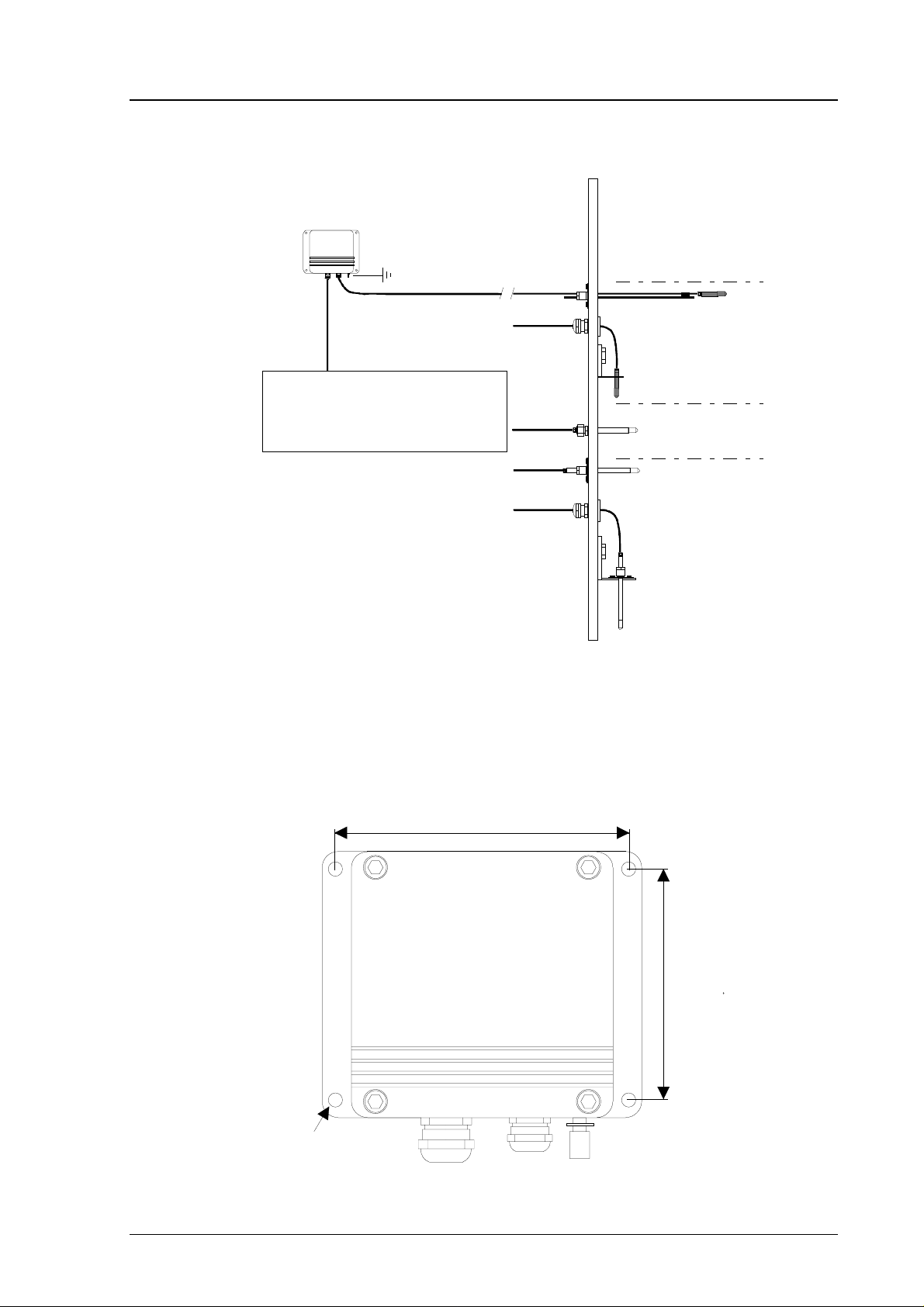
3.2. Mounting
HMP263/264/265
(EEx ia) IIC
Supply voltage 24 VDC
Analog outputs (mA/V)
RS 232C/ RS 485 /digital current loop
SAFE AREA
HAZARDOUS AREA
EEx ia IIC T3/T4
HMP263 sensor head
HMP264 sensor head
for pressurized spaces
HMP265 sensor head
.
Fig. 3.1 Examples of sensor head mounting
The lead-throughs must be sealed properly to avoid air flowing in or out from
the channel. The sealings must fulfil EEx requirements. When using the
support bar with the HMP263, the lead-through piece must be sealed e.g. with
silicon. See also Appendix 8.
133
104
Ø 6.5
Fig. 3.1 Mounting holes in the HMP260 transmitter housings
1997-11-25 5
Page 12

HMP260 SERIES
Operating Manual HMP260-U017en-1.5
The transmitters should be mounted with the sensor head horizontally; this
way, any water condensing on the tube cannot flow onto the sensors. When
there is no alternative but to install the sensor head in the process vertically,
the point of entry must be carefully insulated. The cable must also be allowed
to hang loosely as in Figure 3.6; this prevents any condensed water from
running onto the sensor head along the cable.
If the process temperature is much higher than that of the environment, the
whole sensor head and preferably part of the cable must be inside the process.
When mounted on the side of a duct or channel, the sensor head must be inserted from the side (see Figure 3.7). If this is not possible and the sensor head
must be inserted from the top, the point of entry must be carefully insulated.
NOTE
During installation the protective cover of the
protective unit must not be opened and the sensor head
must not be unsoldered from and then resoldered to the
protective unit of the transmitter. This procedure is not
allowed for the user. Vaisala is not responsible for any
damages caused by incorrect use.
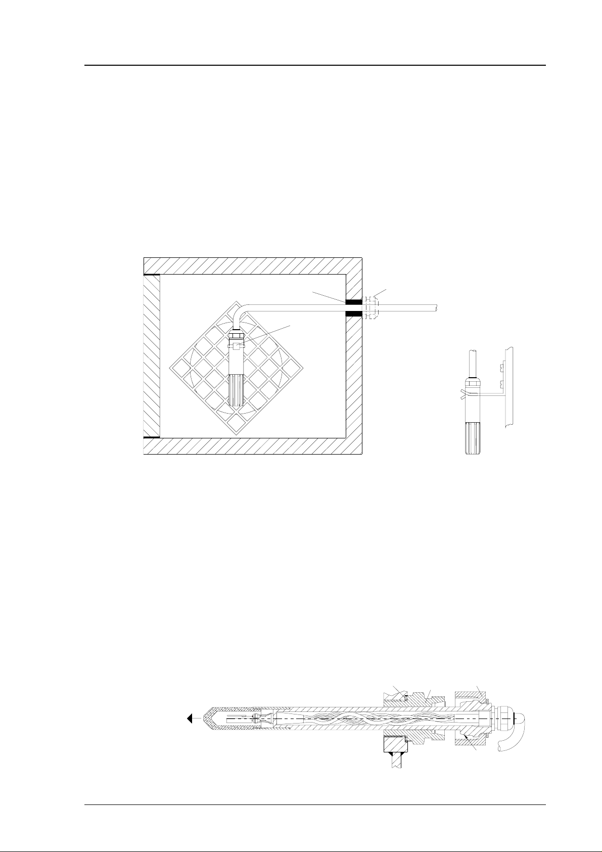
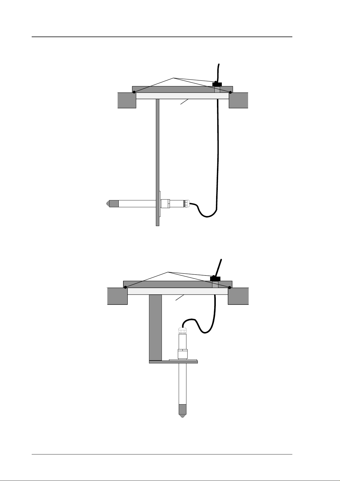
3.2.1. HMP263 transmitter
The HMP263 can be installed in ducts and channels with the help of the installation kit available; the kit consists of a flange, a supporting bar for the
sensor head cable and screws for attaching the flange to the wall of a duct.
With the help of the installation kit the distance between the sensor head and
the channel wall can be easily adjusted. The range of adjustment is 100...320
mm; the distance is measured from the tip of the sensor head to the flange.
duct wall
a plugged hole for reference
measurements
flange
sealing
supporting bar
HAZARDOUS
AREA
SAFE AREA
Fig. 3.2 Installing the sensor head of the HMP263 in a channel with the
help of flange and supporting bar
6 1997-11-25
Page 13
HMP260 SERIES
when a bushing is used, its size is
selected according to the diameter
of the sensor head; the diameter
of the cable increased by using
e.g. tape at the bushing
to be sealed
(loop type)
clamp
mounting the
sensor head
on a support
HAZARDOUS
AREA
SAFE AREA
HMP260-U017en-1.5 Operating Manual
NOTE
When using the support bar the lead-through piece and
the space between the duct wall and the flange must be
sealed e.g. with silicon. The sealings must fulfil EEx
requirements.
The sensor head can also be installed vertically.
Fig. 3.3 Vertical installation of the HMP263 sensor head
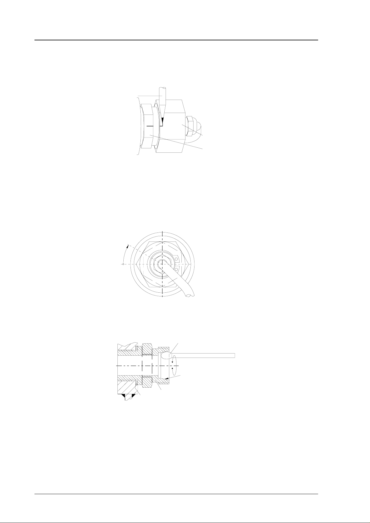
3.2.2. HMP264 transmitter
The HMP264 is supplied with a nut, a fitting body and a sealing washer.
During handling the fitting body and the nut should remain in place on the
body of the sensor head to prevent damage to the highly polished surface.
To achieve a leak-tight assembly:
1. Remove the fitting body from the nut and the sensor head.
2. Fasten the fitting body to the chamber wall. Tighten the fitting body
into the threaded sleeve with a torque spanner. The tightening torque
is 150 ±10 Nm.
HAZARDOUS AREA
sealing washer
fitting body
nut
tightening cone
SAFE AREA
1997-11-25 7
Page 14
HMP260 SERIES
Operating Manual HMP260-U017en-1.5
3. Insert the body of the sensor head into the fitting body and screw the
nut manually to the fitting body until the connection feels tight.
4. Mark both the fitting body and the nut hex.
A pen
nut
fitting body
5. Tighten the nut a further 30° (1/12 turn) or if you have a torque spanner tighten it with a torque of 80 ±10 Nm.
NOTE
After detachment the nut must be tightened without
increased effort.
30°
6. The tightening cone of the fitting body has to be cleaned and greased
after each tenth detachment. Use high-vacuum grease (Down Corning,
Europe) or a similar grease.
clean cotton stick
tightening cone
sealing
washer
fitting body
The sealing washer has to be changed every time the fitting body is
detached.
8 1997-11-25
Page 15
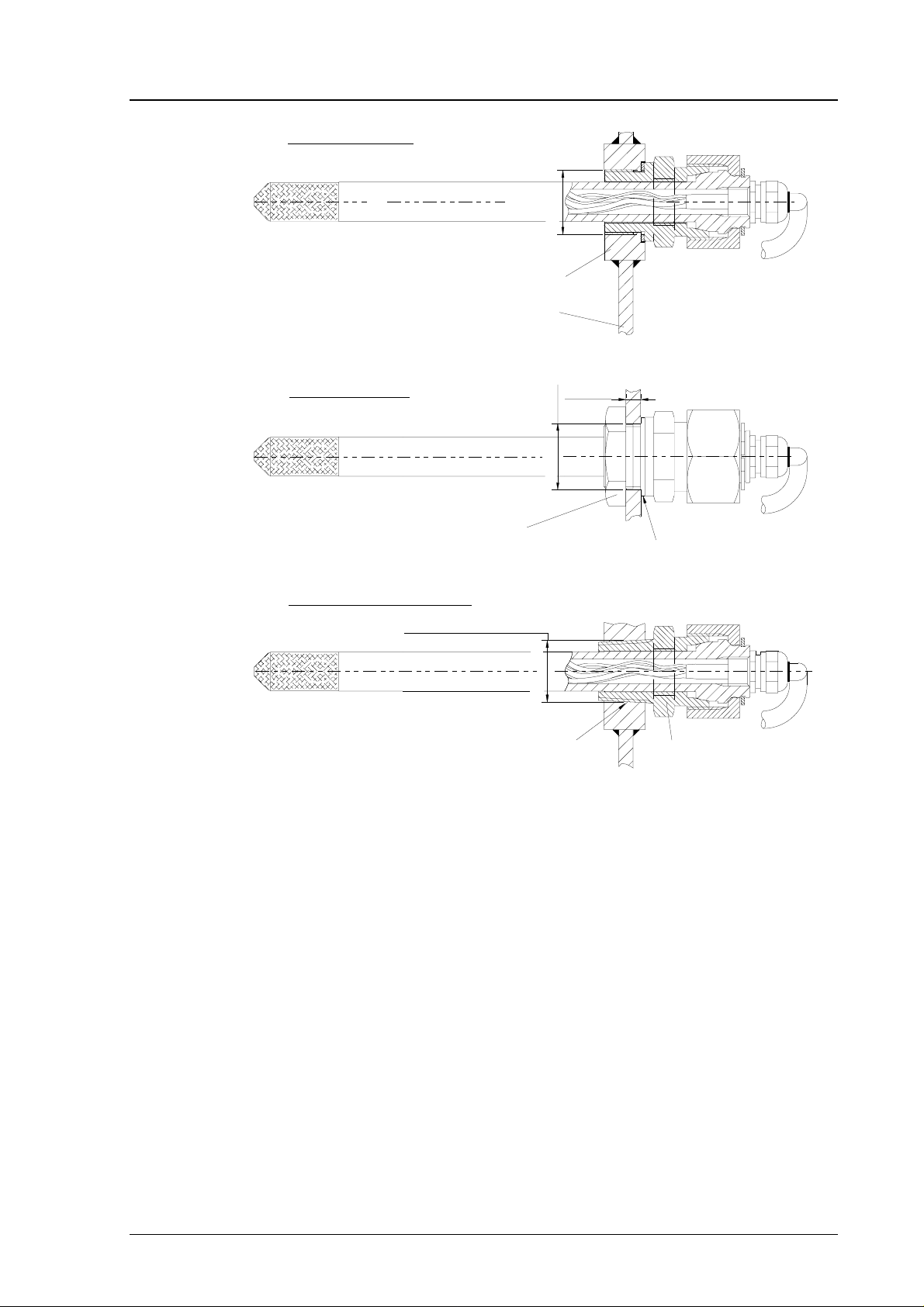
HMP260 SERIES
HMP260-U017en-1.5 Operating Manual
Fasten by threaded sleeve
Sealing by Metal sealing washer DIN 7603
M22x1.5
threaded sleeve M22x1.5/Ø40 x15
sheet metal
Fasten by Nut DIN 80705
Check the thickness of the sheet metal
according to the pressure of the chamber
nut DIN 80705-M22x1.5 (AISI 316)
tightening torque=150 Nm ±10 Nm
NPT Conical pipe threaded connection
ANSI/ASME B1.20.1-1983
sealing by anaerobic pipe thread seal
(SWAK, Cajon Company) or PTFE
(teflon) tape
1/2-14 NPT
(boring)
Ø22+0.3
s=3...6mm
sealing by Metal sealing washer
DIN 7603
fitting body. VAISALA code 17225
(AISI 316Ti). Body hex = 27 mm
tightening torque=150 Nm ±10 Nm
Fig. 3.4 Some examples on the installation of the HMP264 sensor head
1997-11-25 9
Page 16
HMP260 SERIES
Operating Manual HMP260-U017en-1.5
3.2.3. HMP265 transmitter
SAFE AREA
to be sealed
to be insulated
HAZARDOUS AREA
Fig. 3.5 Installing a transmitter in a process with the sensor head hori-
zontally
SAFE AREA
to be sealed
to be insulated
HAZARDOUS AREA
Fig. 3.6 Installing a transmitter in a process with the sensor head down-
wards (not recommended)
10 1997-11-25
Page 17

HMP260 SERIES
HMP260-U017en-1.5 Operating Manual
a plugged hole
HAZARDOUS AREA
for an Exi-approve d
reference meter
SAFE AREA
Fig. 3.7 Mounting the sensor head on a duct or channel
When the sensor head is installed in a duct or a channel, the temperature
difference of the air inside and outside the duct must be small as the sensor
head conducts heat.
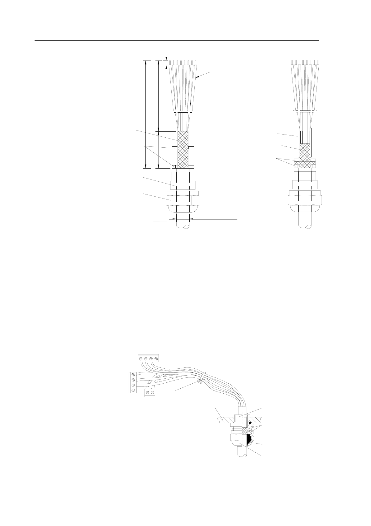
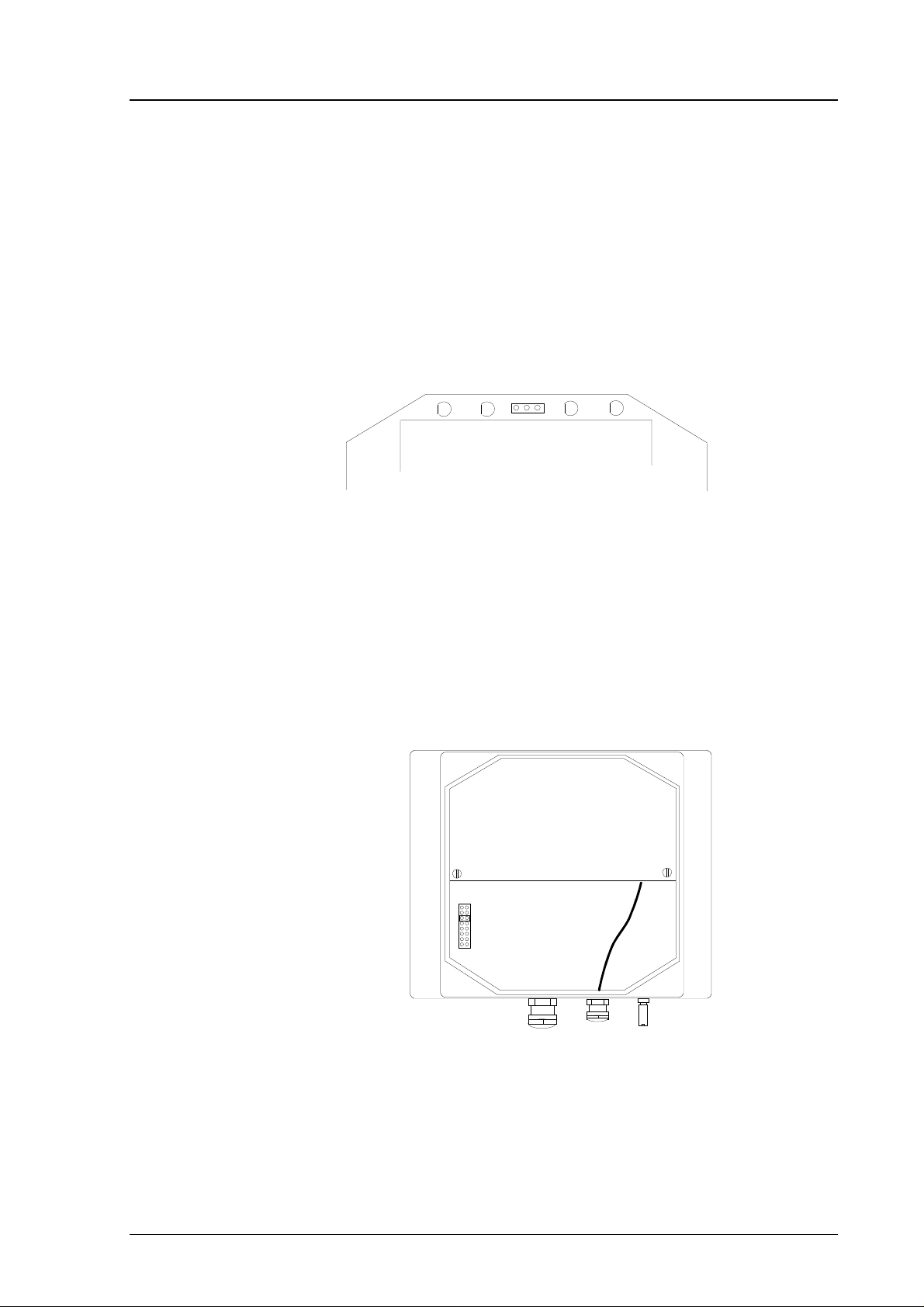
3.3. Grounding
A single electrical cable with a screen and three to ten wires is recommended
for power and analogue output/serial bus connections. The cable diameter
should be 7...10 mm.
The screen of the electrical cable must be grounded properly to achieve best
possible EMC performance. Recommended cable shield is done in the cable
gland as shown below.
• remove the brass disks, rubber ring and nut from the transmitter
housing
• strip 165 mm of the cable insulation, but leave 25 mm of the braid
visible
• slip the nut and rubber ring over the cable insulation
• slip the brass disk that has the bigger hole in it over the braid so that
it rests against the cable insulation
• slip the other brass disk over the wires to the middle of the braid
1997-11-25 11
Page 18
HMP260 SERIES
Operating Manual HMP260-U017en-1.5
braid
rubber
ring
165
brass
disks
nut
cable
140
25
3
flexible wires 0.5 mm
(AWG 20), stranded wires
recommended
D = Ø 7...10
(If the cable diameter is less
than 7mm, use a shrinking
tube or an adhesive tape)
2
shielding tube
braid
brass disks
• push back the braid and press it between the two brass disks to
achieve a full 360° grounding; the fold between the disks should have
the same diameter as the brass disks
• secure the braid with a shielding tube
• insert the wires into the transmitter housing through the gland.
• tighten the nut
• connect the wires into the screw terminals and fasten a cable tie
around the wires
cable tie
transmitter housing
gland
brass disks
rubber ring
nut
12 1997-11-25
Page 19
HMP260 SERIES
HMP260-U017en-1.5 Operating Manual
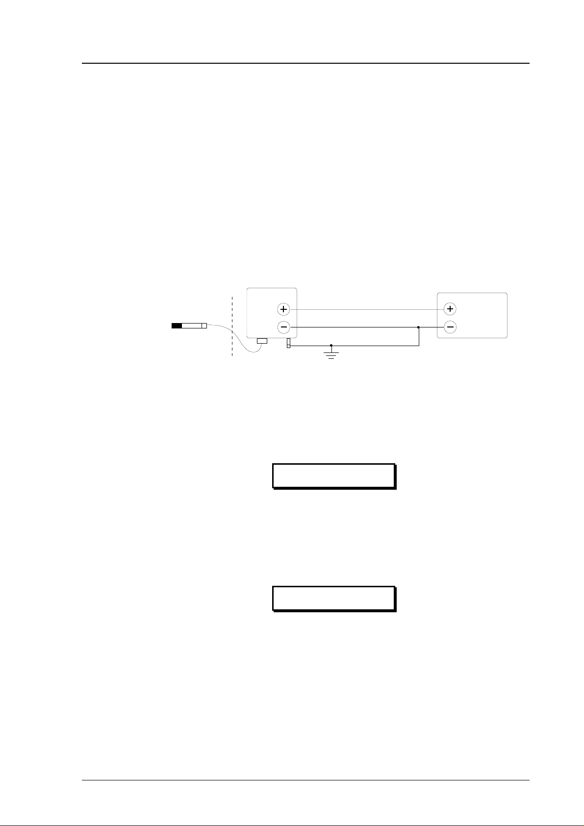
NOTE
When the cable is grounded as above, the metallic parts
of the sensor head, the shield of its cable, the
transmitter housing and the shield of the signal cable to
external system are all connected to each other. The
transmitter housing must be grounded via the
grounding terminal located at the lower right hand
corner of the housing. In addition to this the
negative terminal of the power supply must be
grounded. If these groundings have not been made
correctly, the transmitter does not work.
HMP26x
Hazardous
area
Power
supply
The electrical safety of the grounding must comply with the EN 50014/13
standard. When compliance with Factory Mutual Standards is required, the
grounding must comply with ANSI/ISA RP 12.6 and ANSI/NFPA 70.
Always use the grounding terminal to connect the
transmitter to safety ground.
3.4. Electrical connections
All the component boards are grounded via the housing
frame. Make sure that the fixing screws of the boards
are firmly tightened before connecting the cables.
WARNING
CAUTION
1997-11-25 13
Page 20

HMP260 SERIES
P
Operating Manual HMP260-U017en-1.5
CH1- and CH2- are connected
CH1+
CH1-
CH2+
together internally
CH2-
X2
X1
+-
V
mA
+-
V
mA
24 V +
CURRENT/VOLTAGE
OUTPUTS
EXTERNAL
POWER SUP
Do not use power supply
ground (-) as output signal
ground
OPENED COVER OF THE HMP260
Fig. 3.8 Electrical connections
Power supply 24 VDC
Output signals 0...20 mA
4...20 mA
0...1 V
0...5 V
0...10 V
IF THE CONNECTION INSTRUCTIONS ARE NOT
CAREFULLY FOLLOWED OR THE COMPONENTS
IN THE PROTECTION UNIT ARE MODIFIED OR
TAMPERED WITH, THE DEVICE DOES NOT MEET
THE REQUIREMENTS OF EXi CLASSIFICATION.
VAISALA IS NOT RESPONSIBLE FOR ANY DAMAGES CAUSED BY INCORRECT USE.
14 1997-11-25
Page 21

HMP260 SERIES
HMP260-U017en-1.5 Operating Manual
4. COMMISSIONING
When the HMP260 transmitters leave the factory, their measurement ranges
and output signals have already been selected. The user can subsequently
change the measurement units between metric and non-metric and select and
scale the output signals with software functions, see Chapter 5 Commands and
Appendix 1.
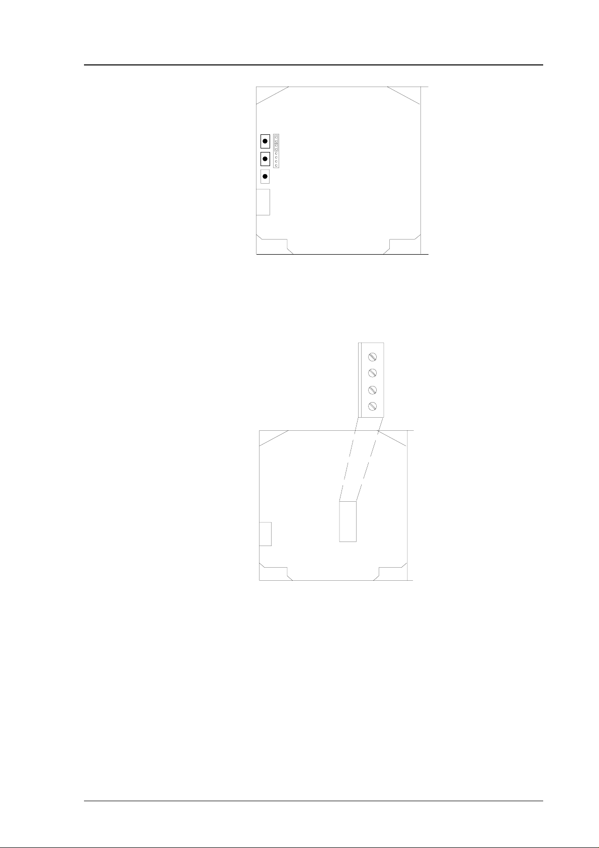
4.1. Security lock jumper
Before the settings can be changed, the security lock jumper in connector X15
must be removed (see Fig. 4.1). The security lock jumper makes it impossible
to change the transmitter settings by mistake.
CHANGE OF SETTINGS
DISABLED
Fig. 4.1 Location of the security lock jumper
When the security lock jumper is connected, some commands are not avail able
(see Chapter 5 Commands).
Should the application require variables that are not included in the
configuration of the transmitter, the user is invited to contact Vaisala or a
Vaisala representative.
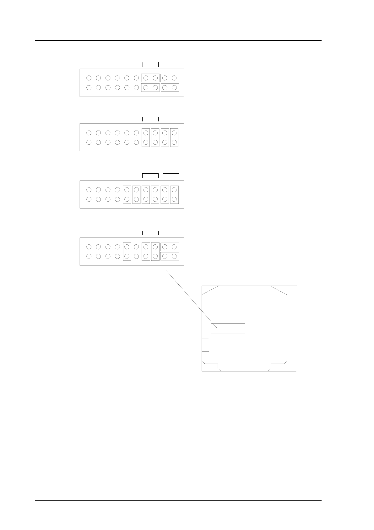
4.2 Selecting the analogue outputs
The HMP260 transmitters can be ordered ready with the current or voltage
outputs required. If the outputs need to be changed, move the jumpers in connector X15 into positions as shown in the Figure 4.2.
X15
1997-11-25 15
Page 22
HMP260 SERIES
Operating Manual HMP260-U017en-1.5
CH1
CH1
CH1
CH1
CH1
CH2
CH1
CH2
CH1
CH2
CH1
CH2
CH2
CURRENT OUTPUTS
0 ... 20 / 4 ... 20 mA
CH2
VOLTAGE OUTPUTS
0 ... 5 V / 0 ... 10 V
CH2
VOLTAGE OUTPUTS
0 ... 1 V
CH2
CH1 0 ... 1 VOLTAGE OUTPUT
CH2 CURRENT OUTPUT
X15
OPENED COVER OF THE HMP260
Fig. 4.2 Selecting the analogue outputs with jumpers
The software has to be informed which outputs are in use. This is done either
through the serial interface or the menus on local display when one is in use.
The serial command is AMODE and the display/keypad command "Mode
Analog outputs Mode" (see Chapter 5 Commands). If the outputs need to
be scaled, see serial command ASCL and the display command "Mode
Analog outputs Scale".
All the jumpers are used only with the 0...1 V outputs. When other outputs are
in use, the spare jumpers are kept in connector X55.
16 1997-11-25
Page 23
HMP260 SERIES
HMP260-U017en-1.5 Operating Manual
X55
spare jumpers
Fig. 4.3 Spare j umpers
4.3 Connecting the RS 232C serial bus
RX
GND
TX
NC
X6
Fig. 4.4 Serial bus connections
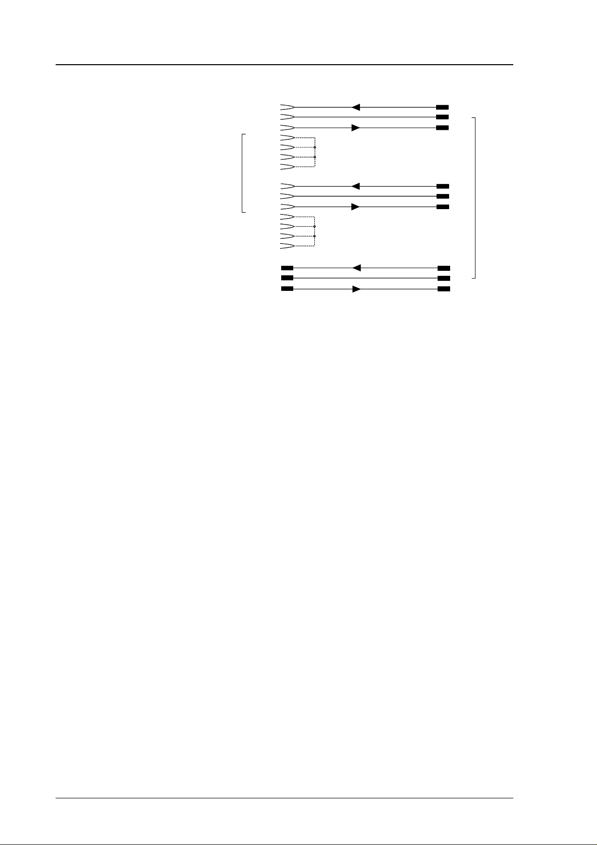
To connect a PC to the HMP260 transmitters via the RS 232C serial bus, one
of the following cables is required. The type of cable depends on the terminal
and the connector type.
1997-11-25 17
Page 24
HMP260 SERIES
3
Operating Manual HMP260-U017en-1.5
RXD
RXD
RXD
TXD
TXD
TXD
TX
GND
RX
TX
GND
RX
TX
GND
RX
HMP 2
PC
TERMINAL
D9S
D25S
D25P
2
5
3
4
6
7
8
3
7
2
5
6
8
20
3
7
2
Fig. 4.5 Connection of cables
When the serial bus has been connected between the PC and the transmitter,
the PC is switched on. When using a PC, a terminal emulation programme
(e.g. Procomm Plus, Datastorm or Windows terminal) is started.
The factory settings for data transfer are:
• 4800 baud
• even parity
• 7 data bits
• 1 stop bit
• full duplex
NOTE
When the serial bus settings are changed, the transmitter has to be reset before the new settings become effective.
The processor does not allow the following combinations:
• no parity, 7 data bits, 1 stop bit: if this combination is given the
HMP260 programme will change the number of stop bits to 2
• even or odd parity, 8 data bits, 2 stop bits: if this combination is given
the programme changes the number of stop bits to 1
Refer to the manuals of the PC and the terminal emulation programme when
giving serial settings.
18 1997-11-25
Page 25
HMP260 SERIES
X
HMP260-U017en-1.5 Operating Manual
The RS 232C screw terminal cannot be used if an RS 485/422 serial module
or a digital current loop module is used. See appendices 3 and 4 on how to
install and operate these modules.
In calibrating or changing the settings of the transmitter it can be more convenient to use the connector X17, if connector X6 is already in use. This connector, however, transfers only RS 232 signals. If an RS 485/422 serial port
module or a digital current loop module has been installed, it has to be
removed before communicating through the X17 connector.
RX GND T
X17
Fig. 4.6 Location and connections of connector X17
4.3.1 Reverting to factory settings of the serial port
If the serial port settings are not known, no commands can be given via the
serial interface. The settings can be reverted to the factory settings by inserting
a jumper in connector X16. The jumper must be i nserted wh en the pow er is
on!
cover of the protection unit
X16
Fig. 4.7 Forcing the serial port settings back to factory settings
When the jumper is inserted the serial line factory settings become valid, but
only temporarily. The transmitter must be given new settings; otherwise
the transmitter uses the old, unknown settings after power-up. When the
new settings have been given, the transmitter must be reset. Note that the
1997-11-25 19
Page 26

HMP260 SERIES
Operating Manual HMP260-U017en-1.5
jumper must be removed before the transmitter is reset. If the jumper is in
place when power i s turned on, the tran smitter does not w ork.
After jumper insertion the transmitter is in STOP mode, ready to receive
commands.
The same method is used when the transmitter is in POLL mode and the user
has forgotten its address.
NOTE
Inserting a jumper in any other place in connector X16
voids the guarantee of the transmitter.
20 1997-11-25
Page 27

HMP260 SERIES
HMP260-U017en-1.5 Operating Manual
5. COMMANDS
As the HMP260 transmitters are microprocessor based devices, their
configuration can be set to correspond to the specific needs of the user. This is
done through commands, either utilizing the menus on the local display or by
giving commands through the serial interface (see Appendix 1). Most often
the commands are used to change the settings of the two analogue channels.
A limited range of commands can be given by using the three press switches up, down and enter - inside the transmitter housing. Four LEDs indicate the
command given with the up and down switches. The switches and LEDs are in
all HMP260 transmitters. LED commands can be used to calibrate the transmitters (both humidity and temperature) or to calibrate the analogue outputs.
A full range of commands can be given through the display/keypad or through
the RS 232C serial bus. The commands can be used e.g. to select and scale the
outputs, to calibrate the humidity and temperature channels as well as the
analogue outputs and to set the serial interface.
5.1 Commands and security lock jumper
In order to prevent any tampering with the transmitter settings, the transmitters
can not be calibrated, the analogue outputs set or the analogue output quantities selected or scaled unless the security lock jumper has been disconnected.
The commands involved are:
• all LED commands
• display/keypad commands:
Cali RH cal T cal
Analog outputs
Mode Analog outputs Mode
• serial commands:
CRH, CT, FCRH, ACAL; AMODE, ASEL, ASCL
In the following, the description of these functions is preceded with a reminder of the security lock jumper:
Disconnect the security lock jumper!
Scale
1997-11-25 21
Page 28
HMP260 SERIES
Operating Manual HMP260-U017en-1.5
5.2 LED commands
NOTE
If the transmitter has a display/keypad cover, the LED
commands cannot be used.
LED commands can be used to operate the transmitters in the field. These
commands can be used in humidity and temperature calibration and calibration
of the analogue outputs.
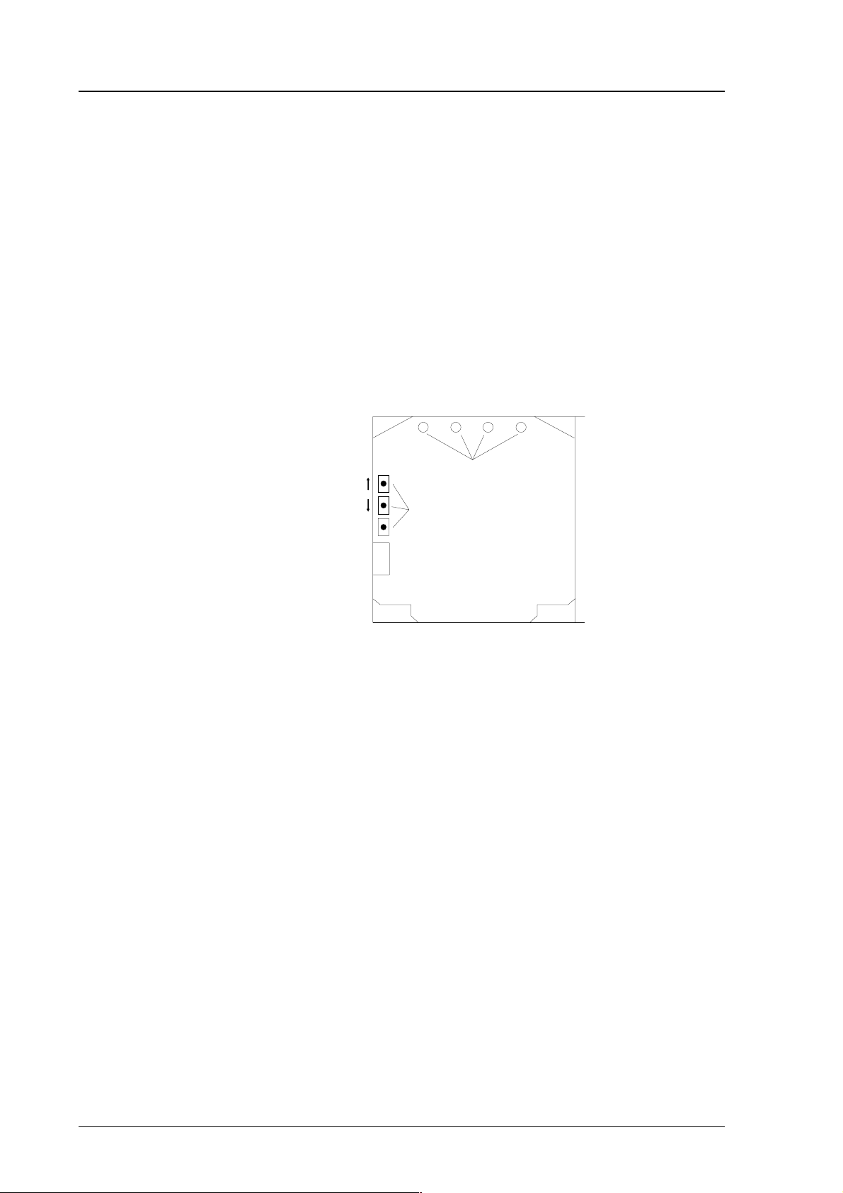
Open the housing and press any one of the three press switches. The LEDs
will light up for 2...3 seconds.
UP
DOWN
ENT
press switches
LEDs
Fig. 5.1 Location of press switches and LEDs
Use the up and down switches (marked with arrows on the printed board) to
find the desired command code and acknowledge it with the ENT switch. The
command codes are (l = lit, ¡ = dark):
¡¡¡¡ (0) return to normal state
¡¡¡l (1) relative humidity calibration
¡¡l¡ (2) tem perature cali bration
¡¡ll (3) calibration of analogue outputs
l¡¡¡ (8) relative humidity calibration after sensor change
22 1997-11-25
Page 29
HMP260 SERIES
HMP260-U017en-1.5 Operating Manual
5.3 Display/keypad commands
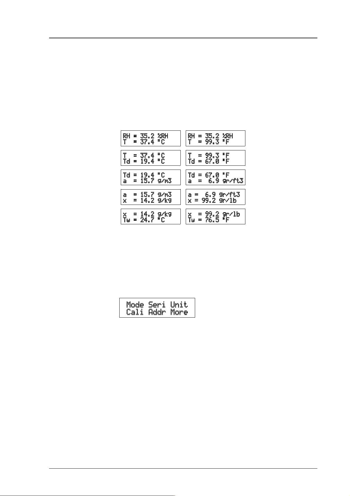
5.3.1 Display mode
In the display mode the transmitters output measurements on the display; different quantities can be scrolled with the arrow keys according to the variables
selected when ordering the transmitter. After reset the transmitters are always
in the display mode.
The display also shows error messages and alarms if they occur.
5.3.2 Command mode
Press the CL key to enter the command mode. The first display is the main
menu:
The commands can be scrolled with the arrow keys. The currently active
commands flashes; a command is selected with the ENT key. When a menu is
displayed, either the first command or the currently valid setting flashes. The
CL key takes the transmitter back to the display mode.
5.3.3 Entering numbers
When the transmitter needs numbers to be entered into the programme (e.g.
when scaling or setting the analogue outputs, in calibration or when giving the
transmitter an address), the field is either empty or the currently valid figure is
displayed. Any previously given value is deleted with the CL key.
When the field is empty, a cursor blinks at the right side of the display.
Pressing the arrow keys brings either a blank ' ', a comma ',', a dash '-', a full
stop '.' or a number from '0' to '9' on the display. The right character is selected
with ENT; after that the number or numbers move left one step. Entering
1997-11-25 23
Page 30
HMP260 SERIES
Operating Manual HMP260-U017en-1.5
numbers is ended with selecting a blank ' ' and pressing ENT. The last character entered can be deleted with CL. If CL or ENT key is pressed when the field
is empty, the programme returns to the previous display.
With some commands (e.g. calibration) the figures are changed using the arrow keys. When an arrow key is pressed continuously for a while, the numbers
start changing at an increasing rate.
5.3.4 Analogue output commands
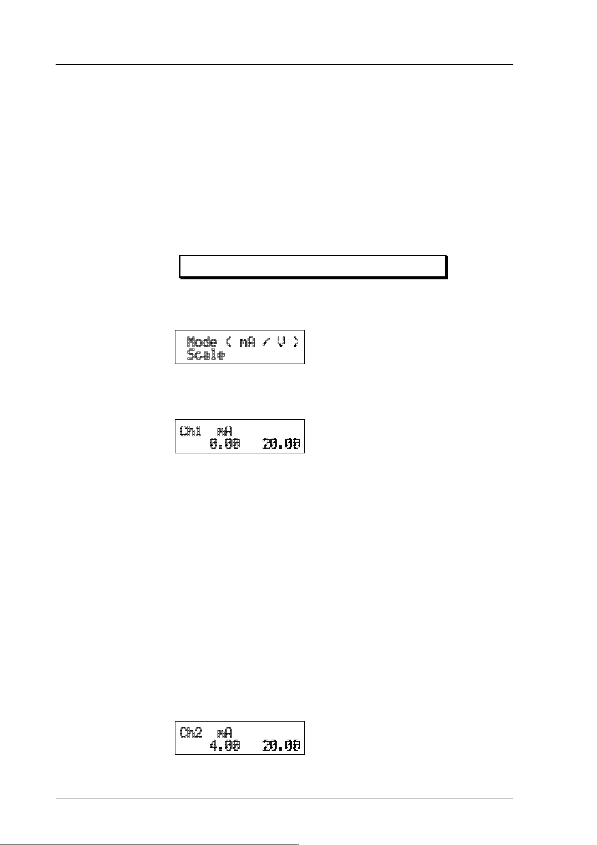
5.3.4.1 Selecting the output (mA/V)
Disconnect the security lock jumper!
• Select Mode in the main menu and Analog outputs in the Mode
menu:
• Select Mode ( mA / V ). The current settings for channel 1 are dis-
played:
• If the settings are correct, press ENT.
• If the settings need to be changed, press CL:
− the quantity (mA/V) starts flashing; it can be changed with the ar-
row keys and acknowledged with the ENT key
− the lower limit starts flashing
− acknowledge the lower limit with ENT or start changing it by
pressing CL; a new lower limit is given one character at a time
with the arrow keys
− the upper limit starts flashing
− acknowledge the upper limit with ENT or start changing it by
pressing CL; a new upper limit is given one character at a time
with the arrow keys
When channel 1 has been set, the programme goes on to channel 2;
the procedure is the same as with channel 1.
24 1997-11-25
Page 31

HMP260 SERIES
HMP260-U017en-1.5 Operating Manual
NOTE
The analogue output jumpers must be set to right places
(see Fig. 4.2).
5.3.4.2 Selecting and scaling the analogue output quantities
Disconnect the security lock jumper!
• Select Mode in the main menu and Analog outputs in the Mode
menu:
• Select Scale. The quantity and scaling for channel 1 are displayed:
• If the settings are correct, press ENT.
• If the settings need to be changed, press CL:
− the quantity (RH, T, Td, x, a Tw) starts flashing; it can be changed
with the arrow keys and acknowledged with the ENT key
− the lower limit starts flashing
− acknowledge the lower limit with ENT or start changing it by
pressing CL; a new lower limit is given with the arrow keys
− the upper limit starts flashing
− acknowledge the upper limit with ENT or start changing it by
pressing CL; a new upper limit is given with the arrow keys
• When channel 1 has been set, the programme goes on to channel 2;
the procedure is the same as with channel 1.
Please note that the selections that are possible are affected by the choice of
output parameters. Also make sure that the temperature measuring ranges are
not exceeded, e.g. the HMP263 can not be used in temperatures above
+120 °C.
1997-11-25 25
Page 32

HMP260 SERIES
Operating Manual HMP260-U017en-1.5
5.3.5 Output via the serial bus
5.3.5.1 Turning the serial interface echo ON/OFF
• Select More in the main menu, select More in the More menu and
select Echo in the second More menu.
• Use the arrow keys to select the right alternative and press ENT.
5.3.5.2 Serial bus settings
• Select Seri in the main menu; the currently valid serial interface set-
tings are displayed:
• If the settings are correct, press ENT; the programme returns to the
display mode.
• If the settings need to be changed, press CL:
• Select the parameter to be changed with the arrow keys and ENT key.
Selecting baud rate:
Selecting parity:
Selecting data bits:
26 1997-11-25
Page 33

HMP260 SERIES
HMP260-U017en-1.5 Operating Manual
Selecting stop bits:
Full duplex/half duplex:
The processor does not allow the following combinations:
• no parity, 7 data bits, 1 stop bit: if this combination is given the
HMP260 programme will change the number of stop bits to 2
• even or odd parity, 8 data bits, 2 stop bits: if this combination is given
the programme changes the number of stop bits to 1
NOTE
The serial bus settings become effective only after reset.
5.3.5.3 Setting the transmitter address
Address is used when more than one transmitters are connected to one serial
bus; this way, it is possible to communicate with one transmitter at a time.
• Select Addr in the main menu; the following is displayed:
• Pressing ENT returns the programme to the main menu.
• Pressing CL deletes the old address; enter the new address with the
arrow keys.
1997-11-25 27
Page 34

HMP260 SERIES
Operating Manual HMP260-U017en-1.5
5.3.5.4 Selecting the output units
• Select Unit in the main menu:
• Use the arrow keys to select the right alternative and press ENT.
metric non-metric
RH %RH %RH
T°C °F
Td °C °F
ag/m3gr/ft
3
x g/kg gr/lb
Tw °C °F
5.3.6 Output modes
The output modes only affect output through the serial interface: the transmitter accepts all display and LED commands irrespective of which serial output
mode it is in. The HMP260 transmitters have three serial output modes: RUN,
STOP and POLL.
In the RUN mode the transmitter outputs measurements automatically through
the serial interface to a PC or a peripheral. The only command that can be
given through the serial interface is S (stop), which ends the RUN mode.
In the STOP mode serial commands are given to the transmitters. Measurements are then output only by entering command SEND.
The POLL mode is used when more than one transmitter is connected to the
same serial bus; a single transmitter can be addressed and communicated with.
When the connection to a given transmitter is opened in the POLL mode, the
transmitter goes into STOP mode and can then receive commands normally.
Closing the connection returns the transmitter to POLL mode. In POLL mode
the transmitter outputs measurement only when requested (command SEND
aa). If the user has forgotten the address of the transmitter and the transmitter
does not have a display, the transmitter has to be reverted to the factory settings (see Chapter 4.3.1). If the transmitter has a display, the settings can be
checked through it.
28 1997-11-25
Page 35

HMP260 SERIES
HMP260-U017en-1.5 Operating Manual
5.3.6.1 Setting the serial interface operation mode
• Select Mode in the main menu; the following is displayed:
• Select Serial output:
• The currently valid setting flashes. Select the desired mode with the
arrow keys and press ENT. After this the programme returns to the
Mode Menu.
• When Run mode is selected, the currently valid output interval is dis-
played:
The output interval setting can be changed as follows:
• press CL
• the number starts flashing
• if the interval needs to be changed, press CL again and enter the new
interval; otherwise press ENT
• the unit (seconds or hours) starts flashing
• the unit can be changed with the arrow keys and acknowledged with
ENT
• after this the programme returns to Mode menu
5.3.7 Others
5.3.7.1 Setting the measurement integration time
By lengthening the measurement integration time any stray changes in the output can be filtered out: the transmitter calculates the average of a number of
measurement cycles defined by the user.
1997-11-25 29
Page 36

HMP260 SERIES
Operating Manual HMP260-U017en-1.5
• Select More in the main menu, select More in the More menu and
select Mtim in the second More menu:
• Pressing ENT returns the programme to the main menu without
changing the integration time.
• If the integration time needs to be changed, press CL; enter the new
integration time with the arrow keys (4...255)
5.3.7.2 Setting the pressure for mixing ratio and wet bulb calculations
The atmospheric pressure has an effect on mixing ratio and wet bulb. Accurate
calculations can be achieved only when the ambient pressure is taken into
consideration.
• Select More in the main menu:
• Select Pressure:
• Pressing ENT returns the programme to the main menu without
changing the pressure reading.
• If the pressure needs to be changed, press CL; enter the new pressure
with the arrow keys
30 1997-11-25
Page 37

HMP260 SERIES
HMP260-U017en-1.5 Operating Manual
5.3.7.3 Setting the date
• Select More in the main menu; select Date in the More menu:
• If the date is correct, acknowledge it by pressing ENT; this takes the
programme back to the More menu.
• If the date needs to be changed, press CL.
− first the centuries (19) start flashing; use the arrow keys to change
them and press ENT
− the years (92) start flashing; use the arrow keys to change them and
press ENT
− the months (06) start flashing; use the arrow keys to change them
and press ENT
− the days (17) start flashing; use the arrow keys to change them and
press ENT
5.3.7.4 Setting the time
• Select More in the main menu; select Time in the More menu:
• If the time is correct, acknowledge it by pressing ENT; this takes the
programme back to the More menu.
• If the time needs to be changed, press CL.
− first the hours (14) start flashing; use the arrow keys to change
them and press ENT
− the minutes (25) start flashing; use the arrow keys to change them
and press ENT
− the seconds (32) start flashing; use the arrow keys to change them
and press ENT
Please note that the transmitter does not have a real-time clock with backup
battery. This means that the date and time settings are not permanent.
1997-11-25 31
Page 38

HMP260 SERIES
Operating Manual HMP260-U017en-1.5
5.4 Serial commands
More detailed descriptions of the serial commands can be found in Appendix
1. Here only the most commonly used command sequences are described. The
instructions on how to connect the HMP260 transmitters to serial bus are
given in Chapter 4.3.
Pressing ESC always interrupts any serial command being given. In the commands <cr> stands for carriage return.
5.4.1 Analogue output commands
5.4.1.1 Setting the analogue outputs
Disconnect the security lock jumper!
AMODE a bb.bbb cc.ccc d ee.eee ff.fff <cr>
a = channel 1: U = voltage output
I = current output
bb.bbb = lower limit of channel 1
cc.ccc = upper limit of channel 1
d = channel 2: U = voltage output
I = current output
ee.eee = lower limit of channel 2
ff.fff = upper limit of channel 2
The bb.bbb, cc.ccc, ee.eee and ff.fff parameters are entered in volts or
milliamperes.
Example:
lower limit of channel 1 is 0 V and upper limit 1 V (U 0 1)
lower limit of channel 2 is 2 V and upper limit 10 V (U 2 10)
AMODE U 0 1 U 2 10 <cr>
Ch1 : 0.000 ... 1.000 V
Ch2 : 2.000 ... 10.000 V
32 1997-11-25
Page 39

HMP260 SERIES
HMP260-U017en-1.5 Operating Manual
5.4.1.2 Selecting and scaling the analogue output quantities
Disconnect the security lock jumper!
ASEL xxx yyy <cr>
xxx = channel 1's quantity
yyy = channel 2's quantity (RH, T, Td, Abs, Mix or Tw)
Example:
relative humidity selected on channel 1 and temperature on channel 2
ASEL RH T <cr>
Ch1 (RH) lo 0.000 %RH ? <cr>
Ch1 (RH) hi 100.000 %RH ? <cr>
Ch2 (T ) lo -40.000 'C ? <cr>
Ch2 (T ) hi +160.000 'C ? <cr>
5.4.1.3 Scaling the analogue outputs
Disconnect the security lock jumper!
ASC L <cr>
Example:
relative humidity is scaled on the range of 0...100 %RH and temperature -
40...+160 °C
ASCL <cr>
Ch1 (RH) lo 0.000 %RH ? <cr>
Ch1 (RH) hi 100.000 %RH ? <cr>
Ch2 (T ) lo 0.000 'C ? -40 <cr>
Ch2 (T ) hi 100.000 'C ? 160 <cr>
1997-11-25 33
Page 40

HMP260 SERIES
Operating Manual HMP260-U017en-1.5
5.4.2 Output via the serial bus
5.4.2.1 Starting the measurement output
R <cr>
Starts output of measurements to the peripheral devices (RUN mode); the only
available command is S (stop).
The output mode can be changed with command FORM (see Appendix 1).
5.4.2.2 Stopping the measurement output
S<cr>
Ends the RUN mode; after this command all other commands are available.
5.4.2.3 Outputting the reading once
SEND <cr> in STOP mode
or
SEND aa <cr> in POLL mode
aa = address of the transmitter when more than one transmitter is
connected to a serial bus (0...99)
The output format depends on which parameters the transmitter can output.
Output types:
"RH=999.9 %RH T=999.9 *C",<cr><lf >
"RH=999.9 %RH T=999.9 *C Td=9999.9 *C",<c r><lf>
"RH=999.9 %RH T=999.9 *C a=9999.9 g/m 3 x=9999.9 g/kg Tw=999.9*C",<c r><lf>
"RH=999.9 %RH T=999.9 *C Td=9999.9 *C a=9999.9 g/m 3 x=9999.9 g/kg Tw=999.9 *C", <cr><lf>
The output mode can be changed with command FORM (see Appendix 1).
34 1997-11-25
Page 41

HMP260 SERIES
HMP260-U017en-1.5 Operating Manual
5.4.2.4 Setting the output interval for the RUN mode
INTV xxx yyy <cr >
xxx = output interval (0...255)
0: no pause between outputs
yyy = unit (s, min or h)
Example:
output interval is changed into 10 minutes
INTV 10 min <cr>
Output intrv. : 10 min
5.4.2.5 Serial bus settings
SERI b p d s x <cr>
b = bauds (300, 600, 1200, 2400, 4800, 9600)
p = parity (n = none, e = even, o = odd)
d = data bits (7 or 8)
s = stop bits (1 or 2)
x = duplex (H = half, F = full)
The processor does not allow the following combinations:
• no parity, 7 data bits, 1 stop bit: if this combination is given the
HMP260 programme will change the number of stop bits to 2
• even or odd parity, 8 data bits, 2 stop bits: if this combination is given
the programme changes the number of stop bits to 1
NOTE
The serial bus settings become effective only after reset.
The settings can be changed one parameter at a time or all parameters at once:
SERI O <cr> changing parity only
4800 O 7 1 HDX
SERI 600 N 8 1 F <cr>
600 N 8 1 FDX
changing all parameters
When the half-duplex mode is set, it will automatically turn the echo off. Even
then the ECHO command can indicate that echo is on.
1997-11-25 35
Page 42

HMP260 SERIES
Operating Manual HMP260-U017en-1.5
5.4.2.6 Selecting the output units
UNIT x <cr>
x = m(etric units)
n(on-metric units)
metric non-metric
RH %RH %RH
T°C °F
Td °C °F
ag/m3gr/ft
3
x g/kg gr/lb
Tw °C °F
5.4.2.7 Setting the transmitter address
ADDR aa <cr>
aa = address (0...99)
Example:
transmitter is given address 99
ADDR <cr>
Address : 2 ? 99 <cr>
5.4.2.8 Resetting the transmitter
RESET <cr>
5.4.3 Operating the transmitter via the serial bus
5.4.3.1 Setting the serial interface
SMODE xxxx<cr>
xxxx = STOP, RUN or POLL
In STOP mode: measurements output only by command, all commands can be
used
In RUN mode: outputting automatically, only command S can be used
36 1997-11-25
Page 43

HMP260 SERIES
HMP260-U017en-1.5 Operating Manual
In POLL mode: measurements output only with command SEND. When in
POLL mode, the output state is changed as follows:
OPEN aa <cr>
SMODE xxxx<cr>
aa = address of the transmitter
xxxx = STOP, RUN or POLL
The OPEN command sets the bus temporarily in STOP mode so that the
SMODE command can be given.
Example:
>SMODE STOP <cr> setting STOP mode
Serial mode : STOP
5.4.3.2 OPEN & CLOSE
OPEN nn <cr>
nn = address of the transmitter (0...99)
CLOSE <cr>
In STOP mode: command OPEN has no effect, CLOSE sets the transmitter in
POLL m o d e
In POLL mode: command OPEN sets the transmitter temporarily in STOP
mode, command CLOSE returns the instrument to POLL
mode
Example:
relative humidity calibration is performed at transmitter 2 which is in POLL
mode
OPEN 2 <cr> opens the line to transmitter 2
CRH <cr> calibration started
...
CLOSE <cr>
1997-11-25 37
line closed
Page 44

HMP260 SERIES
Operating Manual HMP260-U017en-1.5
6. CALIBRATION
The HMP260 transmitters have been fully calibrated at the factory and there
should be no immediate need for recalibration. The transmitters should be
calibrated only if there is reason to believe that the adjustments of the
transmitters have changed. The adjustments of the temperature measurement
channel and the analogue outputs are particularly stable and in normal
circumstances there is no need to recalibrate them. Humidity calibration
should be performed at least once a year.
6.1 Humidity calibration
A two-point calibration can be done with the HMK11 or the HMK13B
Calibrator, or the instrument can be sent to Vaisala. We recommend
recalibration at least once a year. The instruments must be recalibrated every
time the HUMICAP humidity sensor is changed.
The covers of the calibration jars of the HMK11 and HMK13B Calibrator do
not have a hole for the Ø 13.5 mm sensor heads of the HMP260 transmitters;
therefore an adapter must be used when calibrating with the HMK11 or
HMK13B Calibrator. The adapters (part no. 16612 or 16611 respectively) can
be ordered from Vaisala or Vaisala representatives.
Calibration can be performed by giving the commands using the press
switches inside the housing (see Chapter 5.2 LED commands), through the
serial bus (Chapter 5.4 serial commands) or through the menus on the local
display (Chapter 5.3 display/keypad commands).
When LED commands are used and when the two analogue channels do not
output either relative humidity and/or temperature, relative humidity is calibrated on channel 1 and temperature is calibrated on channel 2. The calibration ranges are 0...100 %RH and -20...+80 °C. When the transmitters are
calibrated at two points, the points must be either 50 %RH or 50 °C apart from
each other.
38 1997-11-25
Page 45

HMP260 SERIES
HMP260-U017en-1.5 Operating Manual
NOTE
If the sensor has been changed, the calibration has to be
done according to the instructions in Chapter 6.1.3.
6.1.1. One point calibration procedure
6.1.1.1 Using serial commands
Disconnect the security lock jumper!
• Make sure that the sensors of the transmitter and the reference in-
strument are close to each other. Allow enough time for the sensor
heads to stabilize to the measurement conditions
• Give command CRH <cr> and enter the humidity value and press
<cr>.
>CRH <cr>
RH : xx.x Ref1 ? yy.y <cr>
Press any key when ready...
•
If you want to see how the sensor stabilizes to the reference humidity
enter c <cr> instead of the first reference:
RH : 11.9 Ref1 ? c <cr>
RH : 11.5 Ref1 ? c <cr>
RH : 11.5 Ref1 ? 11.3 <cr>
Press any key when ready...
•
Press any key and press <cr> when the transmitter requests the second
point value.
RH : yy.y Ref2 ? <cr>
6.1.1.2 Using display/keypad commands
Disconnect the security lock jumper!
• Make sure that the sensors of the transmitter and the reference in-
strument are close to each other. Allow enough time for the sensor
heads to stabilize to the measurement conditions
• Select Cali in the main menu and then RH cal; select Not changed
and then one-point offset correction RH 1 point cal. Change the
humidity reading with the arrow keys to correspond to the reference
value and acknowledge it with ENT; pressing an arrow once changes
the reading by 0.05 %RH.
1997-11-25 39
Page 46

HMP260 SERIES
Operating Manual HMP260-U017en-1.5
6.1.1.3 Using LED commands
Disconnect the security lock jumper!
• Make sure that the sensors of the transmitter and the reference in-
strument are close to each other. Allow enough time for the sensor
heads to stabilize to the measurement conditions
• Connect an ammeter/voltmeter to the analogue outputs (connector
X2); if the outputs are already connected e.g. to a process computer
and you do not want to disconnect them, the current output can be
measured at separate test points located next to connector X15 (see
Chapter 7.5). Give command ¡¡¡l (see Chapter 5.2). At the first
calibration point the LED on the left flashes; adjust the humidity point
(offset) with the arrow switches to the reference value. One push of a
switch changes the output by 0.05 %RH; the change of the output
voltage or current depends on the output scaling. Press ENT switch.
The second LED from left starts flashing; press ENT again.
6.1.2 Two point calibration procedure
A two-point humidity calibration should be performed in stable conditions
using saturated salt solutions a reference.
NOTE.
If the humidity sensor has been changed, the calibration
has to be done according to the instructions in Chapter
6.1.3.
6.1.2.1 Using serial commands
Disconnect the security lock jumper!
• Leave the calibrator and the transmitter for at least 4 hours in the
same space so that their temperatures have time to equalize. Remove
the filter cap on the transmitter.
• Place the sensor head into the calibration hole of the LiCl bottle in the
humidity calibrator.
• Wait for 10 minutes.
• Give command CRH <cr> and enter the first point value and press
<cr>.
CRH <cr>
RH : xx.x Ref1 ? yy.y <cr>
Press any key when ready...
40 1997-11-25
Page 47

HMP260 SERIES
HMP260-U017en-1.5 Operating Manual
• If you want to see how the sensor stabilizes to the humidity in the
calibrator, enter c <cr> instead of the first reference:
RH : 11.9 Ref1 ? c <cr>
RH : 11.5 Ref1 ? c <cr>
RH : 11.5 Ref1 ? 11.3 <cr>
Press any key when ready...
Place the sensor head into the calibration hole of the NaCl bottle in
•
the humidity calibrator.
• Wait for 10 minutes.
• Press any key and enter the second point value and press <cr>.
RH : xx.x Ref2 ? yy.y <cr>
The stabilization of the sensor can be monitored by entering c <cr>
•
instead of the reference value.
6.1.2.2 Using display/keypad commands
Disconnect the security lock jumper!
• Leave the calibrator and the transmitter for at least 4 hours in the
same space so that their temperatures have time to equalize. Remove
the filter cap on the transmitter.
• Place the sensor head into the calibration hole of the LiCl bottle in the
humidity calibrator.
• Wait for 10 minutes.
• Select Cali in the main menu and then RH cal; select Not changed
and then two-point calibration RH 2 point cal. Change the first point
reading with the arrow keys and press ENT.
• Place the sensor head into the calibration hole of the NaCl bottle in
the humidity calibrator.
• Wait for 10 minutes.
• If necessary, change the second point reading with the arrow keys and
press ENT.
6.1.2.3 Using LED commands
Disconnect the security lock jumper!
• Leave the calibrator and the transmitter for at least 4 hours in the
same space so that their temperatures have time to equalize. Remove
the filter cap on the transmitter.
• Place the sensor head into the calibration hole of the LiCl bottle in the
humidity calibrator.
1997-11-25 41
Page 48

HMP260 SERIES
Operating Manual HMP260-U017en-1.5
• Wait for 10 minutes.
• Connect an ammeter/voltmeter to the analogue outputs (connector
X2). Give command ¡¡¡l. At the first calibration point the LED
on the left flashes; adjust the first point (offset) with the arrow
switches to the value given in the calibration table (Chapter 6.1.4) and
press ENT switch.
• Place the sensor head into the calibration hole of the NaCl bottle in
the humidity calibrator.
• Wait for 10 minutes.
• Check that the reading corresponds within the desired accuracy to the
reading given in the calibration table (Chapter 6.1.4). If not, adjust the
second point with the arrow switches to the correct value and press
ENT. At the second calibration point the second LED from the left
flashes.
6.1.3 Calibration procedure after sensor change
Humidity calibration should be performed in stable conditions using saturated
salt solutions as a reference.
6.1.3.1 Using serial commands
Disconnect the security lock jumper!
• Leave the calibrator and the transmitter for at least 4 hours in the
same space so that their temperatures have time to equalize. Remove
the filter cap on the transmitter.
• Place the sensor head into the calibration hole of the LiCl bottle in the
humidity calibrator.
• Wait for 10 minutes.
• Give command FCRH <cr> and enter the first point value and press
<cr>:
FCRH <cr>
RH : xx.x Ref1 ? yy.y <cr>
Press any key when ready...
The stabilization of the sensor to the reference humidity can be
•
monitored by giving c <cr>:
RH : 11.9 Ref1 ? c <cr>
RH : 11.5 Ref1 ? c <cr>
RH : 11.5 Ref1 ? 11.3 <cr>
Press any key when ready...
Place the sensor head into the calibration hole of the NaCl bottle in
•
the humidity calibrator.
• Wait for 10 minutes.
42 1997-11-25
Page 49

HMP260 SERIES
HMP260-U017en-1.5 Operating Manual
• Press any key and enter the second point value and press <cr>.
RH : xx.x Ref2 ? yy.y <cr>
The stabilization of the sensor can be monitored by entering c <cr>
•
instead of the reference value.
6.1.3.2 Using display commands
Disconnect the security lock jumper!
• Leave the calibrator and the transmitter for at least 4 hours in the
same space so that their temperatures have time to equalize. Remove
the filter cap on the transmitter.
• Place the sensor head into the calibration hole of the LiCl bottle in the
humidity calibrator.
• Wait for 10 minutes.
• Select Cali in the main menu and then RH cal; select Sensor
changed. Change the first point reading with the arrow keys and
press ENT.
• Place the sensor head into the calibration hole of the NaCl bottle in
the humidity calibrator.
• Wait for 10 minutes.
• If necessary, change the second point reading with the arrow keys and
press ENT.
6.1.3.3 Using LED commands
Disconnect the security lock jumper!
• Leave the calibrator and the transmitter for at least 4 hours in the
same space so that their temperatures have time to equalize. Remove
the filter cap on the transmitter.
• Place the sensor head into the calibration hole of the LiCl bottle in the
humidity calibrator.
• Wait for 10 minutes.
• Connect an ammeter/voltmeter to the analogue outputs (connector
X2). Give command l¡¡¡. At the first calibration point the LED
on the left flashes; adjust the first point with the arrow switches to the
value given in the calibration table (Chapter 6.1.4) and press ENT
switch.
• Place the sensor head into the calibration hole of the NaCl bottle in
the humidity calibrator.
• Wait for 10 minutes.
1997-11-25 43
Page 50

HMP260 SERIES
Operating Manual HMP260-U017en-1.5
• Check that the reading corresponds within the desired accuracy to the
reading in the calibration table. If not, adjust the second point with the
arrow switches to the correct value and press ENT. At the second
calibration point the second LED from the left flashes.
The basic capacitance of the new sensor may differ considerably from that of
the previous one. Therefore the corresponding humidity reading of the
transmitter may be below 0 %RH at the low or above 100 %RH at the high
calibration point. However, the current/voltage reading of the analogue output
shows only the minimum or maximum value of the selected current/voltage
scale and the output value may not change even though the arrow switches are
pressed several times. If this happens, press the up or down arrow switch
continuously to bring the output back into the selected scale; this may take as
long as half a minute.
6.1.4 Humidity calibration table
Temperature °C 15 20 25 30 35
°F 59 68 77 86 95
LiCl %RH *) 11.3 11.3 11.3 11.3
4...20 mA 5.81 5.81 5.81 5.81
0...20 mA 2.26 2.26 2.26 2.26
0...1 V 0.113 0.113 0.113 0.113
0...5 V 0.565 0.565 0.565 0.565
0...10 V 1.13 1.13 1.13 1.13
NaCl %RH 75.6 75.5 75.3 75.1 74.9
4...20 mA 16.10 16.08 16.05 16.02 15.98
0...20 mA 15.12 15.10 15.06 15.02 14.98
0...1 V 0.756 0.755 0.753 0.751 0.749
0...5 V 3.780 3.775 3.765 3.755 3.745
0...10 V 7.56 7.55 7.53 7.51 7.49
Table 1 Greenspan's calibration table
*) LiCl solution must not be used or stored in temperature below +18 °C,
otherwise the equilibrium humidity of the salt solution changes permanently.
6.2 Temperature calibration
The temperature channel has been calibrated at the factory and since it is very
stable, calibration should be performed only when there is strong reason to
believe that the adjustments have changed.
Temperature calibration should be made against some accurate temperature
reference. It can be done either using the press switches inside the housing,
through the serial bus or the menus on the local display. Either a one point or a
two point calibration can be done.
44 1997-11-25
Page 51

HMP260 SERIES
HMP260-U017en-1.5 Operating Manual
6.2.1 One point offset correction
6.2.1.1 Using serial commands
Disconnect the security lock jumper!
• Leave the reference instrument and the transmitter for at least 4 hours
in the same space so that their temperatures have time to equalize.
Remove the filter cap prior to calibration.
• Check the transmitter against the reference.
• Give command CT <cr> and enter the first point value and press
<cr>:
CT <cr>
'T : xx.x Ref1 ? yy.y <cr>
Press any key when ready
If you want to see how the sensor stabilizes to the reference
•
temperature, enter c <cr> instead of the first reference:
T : 0.90 Ref1 ? c <cr>
T : 0.55 Ref1 ? c <cr>
T : 0.55 Ref1 ? 0.0 <cr>
Press any key when ready...
After giving the correct temperature value (Ref1) and pressing <cr>
•
press any key and press <cr>.
6.2.1.2 Using display/keypad commands
Disconnect the security lock jumper!
• Leave the reference instrument and the transmitter for at least 4 hours
in the same space so that their temperatures have time to equalize.
Remove the filter cap prior to calibration.
• Check the transmitter against the reference.
• Select Cali in the main menu and then T cal; select two-point
calibration T 2 point cal. Change the first point reading with the
arrow keys and press ENT.
• Select T 1 point cal, change the reading to correspond to the
reference and press ENT.
1997-11-25 45
Page 52

HMP260 SERIES
Operating Manual HMP260-U017en-1.5
6.2.1.3 Using LED commands
Disconnect the security lock jumper!
• Leave the reference instrument and the transmitter for at least 4 hours
in the same space so that their temperatures have time to equalize.
Remove the filter cap prior to calibration.
• Check the transmitter against the reference.
• Connect an ammeter/voltmeter to the analogue outputs (connector
X2). Give command ¡¡l¡. At the first calibration point the LED
on the left flashes; adjust the first point (offset) with the arrow
switches to the same reading with the reference and press ENT
switch.
• After adjusting the offset point and pressing ENT the second LED
from left flashes. Press ENT without changing the output value.
6.2.2 Two point temperature calibration
6.2.2.1 Using serial commands
Disconnect the security lock jumper!
• Leave the reference instrument and the transmitter for at least 4 hours
in the same space so that their temperatures have time to equalize.
Remove the filter cap prior to calibration.
• Check the transmitter against the reference.
• Give command CT <cr> and enter the first point value and press
<cr>:
CT <cr>
'T : xx.x Ref1 ? yy.y <cr>
Press any key when ready
If you want to see how the sensor stabilizes to the reference
•
temperature, enter c <cr> instead of the first reference:
T : 0.90 Ref1 ? c <cr>
T : 0.55 Ref1 ? c <cr>
T : 0.55 Ref1 ? 0.0 <cr>
Press any key when ready...
Change the temperature and check the transmitter again against the
•
reference.
• Check that the reading corresponds to the reading of the reference
instrument. If not, adjust the second point
• Press any key, enter the second point value and press <cr>.
'T : xx.x Ref2 ? yy.y <cr>
46 1997-11-25
Page 53

HMP260 SERIES
HMP260-U017en-1.5 Operating Manual
• The stabilization of the sensor can be monitored by entering c <cr>
instead of the reference value.
6.2.2.2 Using display/keypad commands
Disconnect the security lock jumper!
• Leave the reference instrument and the transmitter for at least 4 hours
in the same space so that their temperatures have time to equalize.
Remove the filter cap prior to calibration.
• Check the transmitter against the reference.
• Select Cali in the main menu and then T cal; select two-point
calibration T 2 point cal. Change the first point reading with the
arrow keys and press ENT.
• Change the temperature and check the transmitter again against the
reference.
• Check that the reading corresponds to the reading of the reference
instrument. If not, adjust the second point
• If necessary, change the second point reading with the arrow keys and
press ENT.
6.2.2.3 Using LED commands
Disconnect the security lock jumper!
• Leave the reference instrument and the transmitter for at least 4 hours
in the same space so that their temperatures have time to equalize.
Remove the filter cap prior to calibration.
• Check the transmitter against the reference.
• Connect an ammeter/voltmeter to the analogue outputs (connector
X2). Give command ¡¡l¡. At the first calibration point the LED
on the left flashes; adjust the first point (offset) with the arrow
switches to the same reading with the reference and press ENT
switch.
• Change the temperature and check the transmitter again against the
reference.
• Check that the reading corresponds to the reading of the reference
instrument. If not, adjust the second point.
• If necessary, adjust with the arrow switches to the correct value and
press ENT. At the second calibration point the second LED from the
left flashes.
1997-11-25 47
Page 54

HMP260 SERIES
Operating Manual HMP260-U017en-1.5
6.3 Calibration of analogue outputs
The analogue outputs have been calibrated at the factory and since they are
very stable, calibration of the outputs should be performed only when there is
reason to believe that their adjustments have changed.
6.3.1 Using serial commands
Disconnect the security lock jumper!
ACAL < cr>
The outputs on channels 1 and 2 are measured and the measured values (mA
or V) entered as calibration coefficients.
Example: both channels have 0...10 V outputs (set with AMODE command);
enter the voltages measured at the analogue outputs:
>ACAL <cr>
Ch1 U1 ( V ) ? 0.123 <cr>
Ch1 U2 ( V ) ? 9.98 <cr>
Ch2 U1 ( V ) ? 0.120 <cr>
Ch2 U2 ( V ) ? 9.98 <cr>
6.3.2 Using display/keypad commands
Disconnect the security lock jumper!
• Connect an ammeter/voltmeter to the output of channel 1, select Cali
in the main menu and Analog outputs in the Cali menu. The following is displayed (the quantity can be either mA or V):
• Enter the measured lower end current/voltage on channel 1.
• Enter the measured upper end current/voltage on channel 1.
48 1997-11-25
Page 55

HMP260 SERIES
HMP260-U017en-1.5 Operating Manual
• Connect the meter to the output of channel 2 and enter the measured
lower end current/voltage on channel 2.
• Enter the measured upper end current/voltage on channel 2.
6.3.4 Using LED commands
If both the analogue outputs and humidity/temperature channels are calibrated,
the analogue outputs should be calibrated first. This applies only when the
calibrations are made using the LED commands!
• connect an ammeter/voltmeter to the analogue outputs (connector X2)
Disconnect the security lock jumper!
• Give command ¡¡ll.
• the LED on the left flashes; set the low end of channel 1 with the ar-
row keys and press ENT
• the second LED from the left flashes; set the high end of channel 1
with the arrow keys and press ENT
• the LED on the left flashes; set the low end of channel 2 with the ar-
row keys and press ENT
• the second LED from the left flashes; set the high end of channel 2
with the arrow keys and press ENT
The analogue outputs are calibrated to ensure the correct scalin g: for example,
when the output is scaled to 4...20 mA, the low end of the scale is 4 mA and
high end 20 mA exactly. However, when 0... 20 mA output is used, the output
can not be adjusted to exactly 0 mA, but to 50 µA. When 0...1 V, 0...5 V or
0...10 V output is in use, the output is adjusted to 50 mV. The following table
summarizes the correct output values.
Summary of the correct output values:
Output scale:
0...20 mA 4...20 mA 0...1 V 0...5 V 0...10 V
low end: 50 µA 4 mA 50 mV 50 mV 50 mV
high end: 20 mA 20 mA 1 V 5 V 10 V
1997-11-25 49
Page 56

HMP260 SERIES
Operating Manual HMP260-U017en-1.5
7. MAINTENANCE
7.1 Reference measurements
Reference measurements are necessary for the verification of whether the
transmitter readings are within specifications. This way the user can check if
the transmitter needs calibration or service.
The reference meter should preferably use the same technology as the instrument checked, i.e. transmitters with capacitive sensors should be checked with
instruments using capacitive sensors. This minimizes the risk of errors caused
by different measurement techniques.
Whatever technique is used, make sure the reference instrument is at the same
temperature as the checked instrument in order to avoid errors caused by temperature differences. If the sensor head is installed in a potentially explosive
area, the reference instrument must have the same Exi-classification. The
reference measurement should be done as close to the checked sensor as
possible and the readings should be read at the same time, when possible.
The best reference measurements are done in laboratories. If it is possible to
take the transmitter out of process or control system, perform the reference
measurement in a laboratory where the conditions are stable.
7.2 Self-diagnostics
The HMP260 transmitters go through a self-diagnostics procedure when the
power is switched on. If the procedure does not reveal any errors or faults, the
transmitter starts operating normally. If errors or faults are found, first check
whether the humidity and temperature sensors are damaged. If they are intact,
send the transmitter to Vaisala or a Vaisala representative for repairs. The
error messages the transmitter outputs are listed in Appendix 3.
If any errors occur during operation, the error messages are output on the local
display if the transmitter displays measurements; if the menus are used, error
messages are not output. The LEDs indicate errors at all times. During operation, however, the error messages are not output automatically through the serial interface. If there is any reason to doubt that there is something wrong
with the transmitter, use command ERRS:
ERRS <cr>
If there are no error messages, only a prompt is displayed:
>ERRS <cr>
>
50 1997-11-25
Page 57

HMP260 SERIES
HMP260-U017en-1.5 Operating Manual
When errors have occurred, the transmitter outputs the error code (see Appendix 3 for all error messages):
>ERRS <cr>
E40 f ( all ) out of range
>
7.3 Changing the HUMICAP® sensor and the filter
Remove the damaged sensor and insert a new one. Handle the sensor by the
plastic socket. DO NOT TOUCH THE SENSOR PLATE. After sensor change
the humidity calibration must be done according to the instructions in Chapter
6.1.3.
Replace a dirty membrane or sintered filter to ensure a maximum lifetime for
the sensor. Do not try to clean the filter. The sensor can be cleaned with distilled water; if this does not work, replace the sensor.
7.4 Measurement of output currents using test points
If a current output has been connected e.g. to a process computer, the output
current cannot be measured at the output connector X2 without disconnecting
the external load. The output current can, however, be measured at test points
CH1+/CH1- and CH2+/CH2- without disconnecting the output wires. These
test points can therefore be used in one point offset correction against an accurate reference or in checking the current output without disconnecting the
analogue output from the process.
CH1+
CH1-
CH2+
CH2-
X2
CH1 +
X15
+
CH2
OPENED COVER OF THE HMP260
Fig. 7.3 Location of the CH1 and CH2 test points
1997-11-25 51
Page 58

HMP260 SERIES
Operating Manual HMP260-U017en-1.5
mA
X2
CH1+
CH1+
TEST POINTS
CH1-
CH1-
Fig. 7.4 Circuit diagram of the analogue output current test points
7.5 Adjusting the contrast of the display
The contrast of the display can be adjusted using the trimmer "LCD display
contrast" located next to the press switches.
R
L
52 1997-11-25
Page 59

HMP260 SERIES
HMP260-U017en-1.5 Operating Manual
8. TECHNICAL DATA
Specifications of the protection unit, see Appendix 9.
8.1 Relative humidity
Measuring range 0...100 %RH
Accuracy (including nonlinearity and repeatability)
maximum achievable accuracy when calibrated against high quality, certified humidity standards:
±1 %RH (0...90 %RH)
±2 %RH (90...100 %RH)
when calibrated against salt solutions (ASTM E104-85):
±2 %RH (0...90 %RH)
±3 %RH (90...100 %RH)
Response time (90 %) at +20 °C in 15 s
still air (with sintered filter)
Sensor HUMICAP® H-sensor (part no.
8.2 Temperature
Measuring range
HMP263 -40...+120 °C
HMP264 -40 ...+180 °C
HMP265 -40...+180 °C
Typical accuracy of electronics at ±0.1 °C
+20 °C (+68 °F)
Typical temperature dependence of 0.005 °C/°C
electronics
Sensor Pt 100 RTD 1/3 DIN 43760B
8.3 Calculated variables
16663)
Typical ranges
dewpoint temperature -40...+100 °C
mixing ratio 0...500 g/kg dry air
absolute humidity 0...600 g/m
3
wet bulb temperature 0...+100 °C
1997-11-25 53
Page 60

HMP260 SERIES
Operating Manual HMP260-U017en-1.5
Accuracies of the calculated quantities depend on the accuracies of the measured quantities: relative humidity and temperature. In the tables below their
accuracies are ±2 %RH and ±0.2 °C.
Accuracy of dewpoint temperature (°C)
Relative humidity
Temp.
-40 1.86 1.03 0.76 0.63 0.55 0.50 0.46 0.43 - -
-20 2.18 1.19 0.88 0.72 0.62 0.56 0.51 0.48 - -
20 2.87 1.56 1.13 0.92 0.79 0.70 0.64 0.59 0.55 0.53
40 3.24 1.76 1.27 1.03 0.88 0.78 0.71 0.65 0.61 0.58
60 3.60 1.96 1.42 1.14 0.97 0.86 0.78 0.72 0.67 0.64
80 4.01 2.18 1.58 1.27 1.08 0.95 0.86 0.79 0.74 0.70
100 4.42 2.41 1.74 1.40 1.19 1.05 0.95 0.87 0.81 0.76
120 4.86 2.66 1.92 1.54 1.31 1.16 1.04 0.96 0.89 0.84
140 5.31 2.91 2.10 1.69 1.44 1.26 1.14 1.05 0.97 0.91
160 5.80 3.18 2.30 1.85 1.57 1.38 1.24 1.14 1.06 0.99
10 20 30 40 50 60 70 80 90 100
0 2.51 1.37 1.00 0.81 0.70 0.63 0.57 0.53 0.50 0.48
Accuracy of mixing ratio (g/kg) when ambient pressure is 1013 mbar
Relative humidity
Temp. 10 20 30405060 70 8090100
-40 0.003 0.003 0.003 0.003 0.003 0.004 0.004 0.004 - -
-20 0.017 0.018 0.019 0.021 0.022 0.023 0.025 0.026 - 0 0.08 0.09 0.09 0.10 0.10 0.11 0.11 0.12 0.13 0.13
20 0.31 0.33 0.35 0.37 0.39 0.41 0.43 0.45 0.47 0.49
40 0.97 1.03 1.10 1.17 1.24 1.31 1.38 1.46 1.54 1.62
60 2.68 2.91 3.16 3.43 3.72 4.04 4.38 4.75 5.15 5.58
80 6.73 7.73 8.92 10.34 12.05 14.14 16.71 19.92 24.01 29.29
100 16.26 21.34 28.89 40.75 60.86 98.85 183.66 438.56 - 120 40.83 74.66 172.36 - - - - - - -
Accuracy of absolute humidity (g/m3)
Relative humidity
Temp. 10203040506070 8090100
-40 0.004 0.004 0.005 0.005 0.005 0.006 0.006 0.006 - -
-20 0.023 0.025 0.027 0.029 0.031 0.032 0.034 0.036 - 0 0.10 0.11 0.12 0.13 0.13 0.14 0.15 0.15 0.16 0.17
20 0.37 0.39 0.41 0.43 0.45 0.47 0.49 0.51 0.53 0.55
40 1.08 1.13 1.18 1.24 1.29 1.34 1.39 1.44 1.49 1.54
60 2.73 2.84 2.95 3.07 3.18 3.29 3.40 3.52 3.63 3.74
80 6.08 6.30 6.51 6.73 6.95 7.17 7.39 7.61 7.83 8.05
100 12.2 12.6 13.0 13.4 13.8 14.2 14.6 15.0 15.3 15.7
120 22.6 23.3 23.9 24.6 25.2 25.8 26.5 27.1 27.8 28.4
140 39.1 40.0 41.0 42.0 43.0 44.0 45.0 45.9 46.9 47.9
160 63.5 64.9 66.4 67.8 69.2 70.7 72.1 73.5 74.9 76.4
54 1997-11-25
Page 61

HMP260 SERIES
HMP260-U017en-1.5 Operating Manual
Accuracy of wet bulb temperature (°C)
Relative humidity
Temp. 102030405060708090100
-40 0.20 0.20 0.20 0.20 0.20 0.20 0.20 0.20 - -
-20 0.21 0.21 0.22 0.22 0.22 0.22 0.23 0.23 - 0 0.27 0.28 0.28 0.29 0.29 0.29 0.30 0.30 0.31 0.31
20 0.45 0.45 0.45 0.44 0.44 0.44 0.43 0.43 0.42 0.42
40 0.84 0.77 0.72 0.67 0.64 0.61 0.58 0.56 0.54 0.52
60 1.45 1.20 1.03 0.91 0.83 0.76 0.71 0.67 0.63 0.60
80 2.23 1.64 1.32 1.13 0.99 0.89 0.82 0.76 0.72 0.68
100 3.06 2.04 1.58 1.31 1.14 1.01 0.92 0.85 0.80 0.75
120 3.85 2.40 1.81 1.48 1.28 1.13 1.03 0.95 0.88 0.83
140 4.57 2.73 2.03 1.65 1.41 1.25 1.13 1.04 0.97 0.91
160 5.25 3.06 2.25 1.82 1.55 1.37 1.24 1.13 1.05 0.99
The formulas used in calculation of dewpoint, mixing ratio and absolute humidity are presented in Appendix 6. However, when measuring in a high
ambient pressure using HMP264 some corrections are needed in the
calculations. These corrections can be made according to the instructions in
Appendix 6.
8.4 Pressure
Pressure range of the HMP264 0...10 MPa (0...100 bar)
sensor head
8.5 Analogue outputs
Two analogue outputs selectable 0...20 mA 4...20 mA
Typical accuracy of analogue output ±0.05 % full scale
at +20 °C
Typical temperature dependence of 0.005 %/°C full scale
analogue output
8.6 Electronics
User interface 3 keys and 4 LEDs inside the housing
Display 2 x 16 character alphanumeric high-
0...1 V 0...5 V
0...10 V
or local display keypad
contrast, wide view angle LCD
character height 3.85 mm (0.15")
Keyboard 1 x 4 keypad
1997-11-25 55
Page 62

HMP260 SERIES
Operating Manual HMP260-U017en-1.5
Connections screw terminals, 0.5 mm2 wires (AWG
20), stranded wires recommended
Operating voltage 24 VDC (20...28 V)
Power consumption 120 mA maximum (24 VDC)
Recommended external load for <500 Ω
current outputs
Recommended external load for >2 kΩ (to ground)
0...1 V voltage output
Recommended external load for >10 kΩ (to ground)
0...5 and 0...10 V voltage outputs
Operating temperature (electronics) -40...+60 °C
with display 0...+50 °C
Storage temperature -40...+70 °C
8.7 Mechanics
Housing material G-AlSi12 (DIN 1725)
Housing classification IP 65 (NEMA 4)
Bushing for 7...10 mm diameter cable (8 x
Sensor protection stainless steel sintered filter (part no.
Housing dimensions 145 x 120 x 65 mm
Sensor head dimensions see figures 8.1...8.3)
Cable diameter 5.5 mm
0.5 mm2 shielded cable)
16452)
PPS grid with stainless steel netting
(part no. 16720)
PPS grid (part no. 16562)
56 1997-11-25
Page 63

HMP260 SERIES
m
m
m
HMP260-U017en-1.5 Operating Manual
Ø 13.5
29
70
Ø 13.5
cable length 2000,
5000, 10 000 or 15 000
Fig. 8.1 HMP263 sensor head dimensions
Fitting body h ex=2 7
Ø 13.5
29
120
170
M22x1.5
14
Nut hex=32
Fig. 8.2 HMP264 sensor head dimensions
Ø 9.5
Ø 55
Ø 75
13.5
Ø
29
13.5
Ø
cable length 2000,
5000, 10 000 or 15 000
25
Ø
2.5
30
220
cable length
2000, 5000,
10000 or 15000
Fig. 8.3 HMP265 sensor head and flange dimensions
Weight (without display cover):
with 2 m cable 5 m cable 10 m cable 15 m cable
HMP263 (+ 120°C cable) 1260 g 1500 g 2000 g 2500 g
HMP264 (+ 180°C cable)
HMP265 (+ 180°C cable)
1400 g 1700 g 2200 g 2700 g
1600 g 1900 g 2400 g 2900 g
Weight of display cover 420 g
1997-11-25 57
Page 64

HMP260 SERIES
Operating Manual HMP260-U017en-1.5
8.8 Electromagnetic compatibility
The emission and immunity tests have been performed according to standards
EN50081-1 and EN50082-2.
NOTE
These tests are valid with specified sensor protections
only.
Type: Sensor protection/notes:
HMP263 PPS grid & stainless steel netting
(part no. 16720)
HMP264 sintered filter (part no. 16452)
HMP265 sintered filter (part no. 16452), PPS grid &
stainless steel netting (part no. 16720)
8.8.1 Emissions
Test: Setup according to:
Radiated interference EN55022 (class B)
8.8.2 Immunity
Test: Setup according to: Performance:
Electrostatic discharge EN61000-4-2:1995 criteria B
Electrical fast transients EN61000-4-4:1995 criteria B
GSM field immunity ENV50204:1995 criteria A
RF radiated fields ENV50140:1993 criteria A
RF conducted fields ENV50141:1993 criteria A
Voltage proof, AC: DC supply (+ or -) to housing 250 VAC, 1 minute (300 kΩ
and 15 nF parallel)
58 1997-11-25
Page 65

HMP260 SERIES
HMP260-U017en-1.5 Operating Manual
9. OPTIONS
Mounting flanges for HMP265 aluminium
stainless steel for harsh conditions
Installation kit for HMP263 aluminium flange
Cable length 2, 5, 10 or 15 metres
10. SPARE PARTS
Order code Description
HMP235FS Mounting flange for HMP265, stainless steel
HMP235FA Mounting flange for HMP265, aluminium
HMP233FAH Mounting kit for HMP263
16452 Sintered filter, stainless steel
16720 PPS grid with stainless steel netting
16562 PPS grid
16663 HUMICAP humidity sensor (-40...+180 °C)
16612 Calibration adapter for the HMK11 Calibrator
HMP230RS RS 485/422 serial module
HMP230CL Digital current loop module
17223 Fitting body for HMP264 (standard)
17225 NTP conical pipe threaded fitting body for
HMP264 (1/2 - 14 NPT)
GUARANTEE
Vaisala issues a guarantee for the material and workmanship of this product
under normal operating condition for one (1) year from the date of delivery.
Exceptional operating conditions, damage due to careless handling and
misapplication will void the guarantee.
1997-11-25 59
Page 66

HMP260 SERIES
HMP260-U017en-1.5 Appendix 1: Serial commands
SERIAL COMMANDS
1 ANALOGUE OUTPUT COMMANDS ............................................................................... 2
AMODE Setting the analogue outputs ................................................................2
ASEL Selecting the scaling the analogue output quantities............................... 2
ASCL Scaling the analogue outputs ............................................................... 3
2 CALIBRATION COMMANDS..........................................................................................5
CRH Relative humidity calibration.................................................................5
FCRH Relative humidity calibration after sensor change....................................6
CT Temperature calibration........................................................................6
ACAL Calibrating the analogue outputs........................................................... 7
L Outputting linear correction coefficients................................................. 7
LI Entering linear correction coefficients.................................................... 8
3 OUTPUT VIA THE SERIAL BUS .................................................................................... 9
R Starting the measurement output.......................................................... 9
S Stopping the measurement output ........................................................9
SEND Outputting a reading once.................................................................... 9
DSEND Outputting readings of all connected transmitters once.........................10
ERRS Outputting error messages.................................................................10
ECHO Turning the serial interface echo ON/OFF............................................11
INTV Setting the output interval for the RUN state......................................... 11
FORM Setting the output format....................................................................12
FTIME Adding time to output ........................................................................13
FDATE Adding date to output ........................................................................ 14
SERI Serial bus settings ............................................................................14
UNIT Selecting the output units..................................................................15
ADDR Setting the transmitter address...........................................................16
RESET Resetting the transmitter....................................................................16
3.1 Operation modes........................................................................................... 16
SMODE Setting the serial interface.................................................................. 16
OPEN & CLOSE ..............................................................................................17
4 OTHERS..................................................................................................................... 18
ITEST Testing the analogue outputs..............................................................18
MTIM Setting the measurement integration time............................................18
PRES Setting the pressure for mixing ratio and wet bulb calculations ..............19
XPRES Setting the pressure for mixing ratio and wet bulb calculations
temporarily ......................................................................................19
CDATE Entering calibration date....................................................................20
DATE Setting the date................................................................................20
TIME Setting the time ................................................................................20
VERS Name and version of the programme ...................................................21
? Outputting the transmitter settings......................................................21
?? Outputting the transmitter settings also in POLL mode.........................21
The commands function as described when the serial interface is in fullduplex mode and echo is on. All commands except FORM can be given in
either capital or small letters.
In the commands <cr> means carriage return, <lf> line feed and <ht> horizontal tabulation.
Page 67

HMP260 SERIES
Appendix 1: Serial commands HMP260-U017en-1.5
Page 68

HMP260 SERIES
HMP260-U017en-1.5 Appendix 1: Serial commands
1 ANALOGUE OUTPUT COMMANDS
AMODE Setting the analogue outputs
Disconnect the security lock jumper!
AMODE a bb.bbb cc.ccc d ee.eee ff.fff <cr>
a = channel 1: U = voltage output
I = current output
bb.bbb = lower limit of channel 1
cc.ccc = upper limit of channel 1
d = channel 2: U = voltage output
I = current output
ee.eee = lower limit of channel 2
ff.fff = upper limit of channel 2
The bb.bbb, cc.ccc, ee.eee and ff.fff parameters are entered in volts or milliamperes.
Sets the analogue outputs on channels 1 and 2. An example of this is when the voltage
output on channel 1 is set to be 0...1 V and channel 2 set to 2...10 V:
AMODE U 0 1 U 2 10 <cr>
Ch1 : 0.000 ... 1.000 V
Ch2 : 2.000 ... 10.000 V
The current settings can be checked by giving the command without any parameters:
AMODE <cr>
Ch1 : 0.000 ... 20.000 mA
Ch2 : 0.000 ... 20.000 mA
ASEL Selecting the scaling the analogue output quantities
Disconnect the security lock jumper!
ASEL xxx yyy <cr>
xxx = channel 1's quantity
yyy = channel 2's quantity (RH, T, Td, Abs, Mix or Tw)
For example, relative humidity is selected to be output on channel 1 and temperature on
channel 2; the temperature range is scaled to 0...100 °C:
Page 69

HMP260 SERIES
Appendix 1: Serial commands HMP260-U017en-1.5
ASEL RH T <cr>
Ch1 (RH) lo 0.000 %RH ? <cr>
Ch1 (RH) hi 100.000 %RH ? <cr>
Ch2 (T ) lo -40.000 'C ? 0 <cr>
Ch2 (T ) hi +160.000 'C ? 100 <cr>
When the ASEL command is given on its own, the transmitter outputs its current
settings:
ASEL <cr>
Ch1 (RH) lo 0.000 %RH
Ch1 (RH) hi 100.000 %RH
Ch2 (T ) lo -40.000 'C
Ch2 (T ) hi +160.000 'C
The outputs and their scales can also be given directly with the ASEL command.
ASEL xxx yyy aaa.a bbb.b ccc.c ddd.d <cr>
xxx = channel 1's quantity
yyy = channel 2's quantity
aaa.a = lower limit of channel 1
bbb.b = upper limit of channel 1
ccc.c = lower limit of channel 2
ddd.d = upper limit of channel 2
ASCL Scaling the analogue outputs
Disconnect the security lock jumper!
ASCL <cr>
Scales the outputs selected on channels 1 and 2.
For example, scaling relative humidity on the range of 0...100 %RH and temperature -
40...+160 °C:
ASCL <cr>
Ch1 (RH) lo 0.000 %RH ? <cr>
Ch1 (RH) hi 100.000 %RH ? <cr>
Ch2 (T ) lo 0.000 'C ? -40 <cr>
Ch2 (T ) hi 100.000 'C ? 160 <cr>
Page 70

HMP260 SERIES
HMP260-U017en-1.5 Appendix 1: Serial commands
The output scales can also be given directly with the ASCL command.
ASCL aaa.a bbb.b ccc.c ddd.d <cr>
aaa.a = lower limit of channel 1
bbb.b = upper limit of channel 1
ccc.c = lower limit of channel 2
ddd.d = upper limit of channel 2
For example, when relative humidity is scaled to 0...100 %RH on channel 1 and
temperature to -40...+100 °C on channel 2:
ASCL 0 100 -40 100 <cr>
Ch1 (RH) lo 0.000 %RH
Ch1 (RH) hi 100.000 %RH
Ch2 (T ) lo -40.000 'C
Ch2 (T ) hi 100.000 'C
Page 71

HMP260 SERIES
Appendix 1: Serial commands HMP260-U017en-1.5
2 CALIBRATION COMMANDS
CRH Relative humidity calibration
Disconnect the security lock jumper!
CRH <cr>
With this command the transmitters can be calibrated against a reference. A one-point
calibration can be done against an accurate transfer standard in the field and a two-point
calibration using saturated salt solutions in controlled conditions. A two-point calibration
is performed as follows:
CRH <cr>
RH : 12.00 Ref1 ? 11.3 <cr>
Press any key when ready ...
RH : 76.00 Ref2 ? 75.5 <cr>
In one-point offset correction, the Ref2 prompt is acknowledged with <cr>:
CRH <cr>
RH : 12.80 Ref1 ? 11.3 <cr>
Press any key when ready ...
RH : 75.50 Ref2 ? <cr>
If the stabilization of the sensor to the humidity in the calibrator needs to be monitored,
the measurement output can be repeated by giving command c<cr> at Ref1 and Ref2:
CRH <cr>
RH : 12.00 Ref1 ? c <cr>
RH : 11.70 Ref1 ? c <cr>
RH : 11.50 Ref1 ? 11.3 <cr>
Press any key when ready ...
RH : 76.00 Ref2 ? 75.5 <cr>
Page 72

HMP260 SERIES
HMP260-U017en-1.5 Appendix 1: Serial commands
FCRH Relative humidity calibration after sensor change
Disconnect the security lock jumper!
FCRH <cr>
After humidity sensor change the transmitter must be calibrated using this command and
the calibration must be done at two reference points. The calibration is performed as
follows:
FCRH <cr>
RH : 1.90 Ref1 ? 11.3 <cr>
Press any key when ready ...
RH : 76.30 Ref2 ? 74.9 <cr>
The command can also be divided into two commands, so the computer can be used
for other purposes while waiting for the sensor to stabilize to the higher humidity.
FCRH 1 <cr>
RH : 1.90 Ref1 ? 11.3 <cr>
FCRH 2 <cr> ...
RH : 76.30 Ref2 ? 74.9 <cr>
If the stabilization of the sensor to the humidity in the calibrator needs to be monitored,
the measurement output can be repeated by giving command c<cr> at Ref1 and Ref2:
FCRH <cr>
RH : 12.00 Ref1 ? c <cr>
RH : 11.70 Ref1 ? c <cr>
RH : 11.50 Ref1 ? 11.3 <cr>
Press any key when ready ...
RH : 76.00 Ref2 ? 75.5 <cr>
CT Temperature calibration
Disconnect the security lock jumper!
CT <cr>
With this command the transmitters can be calibrated against an accurate reference,
such as a Pt 100 simulator. A two-point calibration is performed as follows:
CT <cr>
T : 0.80 Ref1 ? 0.0 <cr>
Press any key when ready ...
T : 56.20 Ref2 ? 55.0 <cr>
Page 73

HMP260 SERIES
Appendix 1: Serial commands HMP260-U017en-1.5
In one-point offset correction, the Ref2 prompt is acknowledged with <cr>:
CT <cr>
T : 0.80 Ref1 ? 0.0 <cr>
Press any key when ready ...
T : 75.50 Ref2 ? <cr>
If the stabilization of the sensor to the temperature of the calibrator or the reference
needs to be monitored, the measurement output can be repeated by giving command
c<cr> at Ref1 and Ref2:
CT <cr>
T : 0.80 Ref1 ? c <cr>
T : 0.40 Ref1 ? 0.00 <cr>
Press any key when ready ...
T : 56.20 Ref2 ? 55.0 <cr>
ACAL Calibrating the analogue outputs
Disconnect the security lock jumper!
ACAL <cr>
Calibrates the outputs selected on channels 1 and 2. The output is measured and the
measured values (mA or V) entered as calibration coefficients.
For example, calibrating the outputs when 0...10 V signal has been selected on both
channels (set with AMODE command)
ACAL <cr>
Ch1 U1 (V ) ? 0.123 <cr>
Ch1 U2 (V ) ? 9.98 <cr>
Ch2 U1 (V ) ? 0.120 <cr>
Ch2 U2 (V ) ? 9.98 <cr>
L Outputting linear correction coefficients
L <cr>
With the help of command L the user can check how the transmitter has been
adjusted after it has been calibrated at the factory.
L <cr>
RH offset : 0.000
RH gain : 1.000
T offset : 0.000
T gain : 1.000
Page 74

HMP260 SERIES
HMP260-U017en-1.5 Appendix 1: Serial commands
LI Entering linear correction coefficients
Disconnect the security lock jumper!
LI <cr>
The LI command is one way of calibrating the transmitters.
LI <cr>
RH offset : 0.000 ? -.6 <cr>
RH gain : 1.000 ? <cr>
T offset : 0.000 ? <cr>
T gain : 1.000 ? .4 <cr>
The factory settings are offset 0 and gain 1. The transmitter can be returned to its
factory calibration by giving these values.
NOTE
The temperature unit in offset correction is always degrees
Centigrade, even if the transmitter is using non-metric units
(Fahrenheit) in its measurement output.
Page 75

HMP260 SERIES
Appendix 1: Serial commands HMP260-U017en-1.5
3 OUTPUT VIA THE SERIAL BUS
R Starting the measurement output
R <cr>
Starts output of measurements to the peripheral devices (PC display or printer); output
interval is set with command INTV.
The output format depends on the transmitter configuration and the variables in use. The
order, however, is always the same: relative humidity, temperature, dewpoint
temperature, absolute humidity, mixing ratio and wet bulb temperature. An example:
RH= 43.0 %RH T= 21.0 'C Tdp= 8.0 'C x= 6.7 g/kg Tw= 13.7 'C <cr><lf>
When the transmitter sends out the readings, the serial interface does not echo any
commands; the only command that can be used is S (stop).
The output mode can be changed with command FORM.
S Stopping the measurement output
S<cr>
Ends the RUN mode; after this command all other commands are available.
SEND Outputting a reading once
SEND <cr> in STOP mode
or
SEND aa <cr> in POLL mode
aa = address of the transmitter when more than one transmitter is con-
nected to a serial bus (0...99; set with command ADDR)
Outputs the current measurement readings via the serial line. The output format depends
on which parameters the transmitter can output. Output types are:
"RH=999.9 %RH T=999.9 'C",<cr><lf>
"RH=999.9 %RH T=999.9 'C Td=9999.9 'C",<cr><lf>
"RH=999.9 %RH T=999.9 'C a=9999.9 g/m3 x=9999.9 g/kg Tw=999.9 'C",<cr><lf>
"RH=999.9 %RH T=999.9 'C Td=9999.9 'C a=9999.9 g/m3 x=9999.9 g/kg Tw=999.9
'C",<cr><lf>
Page 76

HMP260 SERIES
HMP260-U017en-1.5 Appendix 1: Serial commands
The output mode can be changed with command FORM.
DSEND Outputting readings of all connected transmitters once
DSEND <cr>
All transmitters connected to the serial bus send their addresses and current
measurement readings in an order defined by their addresses. After receiving DSEND
command a transmitter sets a delay time according to its address value and sends the
data after this delay. DSEND works also in POLL mode. With this command the user
can, for example, easily find out the addresses of the transmitters.
The output when four transmitters with addresses 4, 5, 10, 33 have been connected to
the serial bus:
>dsend <cr>
4 14.43 %RH
5 22.7 'C
10 14.99 %RH
33 22.3 'C
>
ERRS Outputting error messages
ERRS <cr>
During operation error messages are not automatically output through the serial
interface. If there is any reason to doubt that there is something wrong with the
transmitter, possible error messages can be output with command ERRS.
If there are no error messages, only a prompt is displayed:
>ERRS <cr>
>
If errors have occurred, the transmitter outputs the error code (see Appendix 5 for error
messages):
>ERRS <cr>
E40 f ( all ) out of range
>
Page 77

HMP260 SERIES
Appendix 1: Serial commands HMP260-U017en-1.5
ECHO Turning the serial interface echo ON/OFF
ECHO xxx <cr>
xxx = ON or OFF
When the echo is off, the commands given through the serial interface or the prompt >
cannot be seen on the display.
When the serial interface is in half-duplex mode, the echo is always off. Even then the
ECHO command can indicate that echo is on.
INTV Setting the output interval for the RUN mode
INTV xxx yyy <cr>
xxx = output interval (0...255)
0: no pause between outputs
yyy = unit (s, min or h)
Sets the output interval when the transmitter outputs measurement readings to a
peripheral device.
For example, the currently valid settings are output with:
INTV <cr>
Output intrv. : 0 min
When this is changed into 10 minutes, the command is:
INTV 10 <cr>
Output intrv. : 10 min
The unit is changed into seconds with:
INTV S <cr>
Output intrv. : 10 s
The change can also be done with one command:
INTV 10 S <cr>
Output intrv. : 10 s
Page 78

HMP260 SERIES
HMP260-U017en-1.5 Appendix 1: Serial commands
FORM Setting the output format
FORM <cr>
"xxx...xxx"
? zzz...zzz <cr>
xxx...xxx = old format
zzz...zzz = new format
The FORM command sets the format of the outputs generated in RUN mode and by
SEND command. Please note that capital and small letters have different
meanings.
\UU..UU\ relative humidity
\TT..TT\ temperature
\DD..DD\ dewpoint temperature
\AA..AA\ absolute humidity
\XX..XX\ mixing ratio
\WW..WW\ wet bulb temperature
\uu..uu\ unit according to the preceding variable
\n line feed <lf>
\r carriage return <cr>
\t horizontal tabulation <ht> or <tab>
\\ \
For example:
format: output:
\UUU.UU\ \+TT.TT\\r 100.00 +99.99 <cr>
\TTT.T\ \uu\\r\n 15.2 'C <cr><lf>
\UUU.U\ \uuu\\+DD.D\ \uu\\r 46.9 %RH +10.8 'C <cr>
Any text can be written in the command and it appears in the output. For example:
RH: \UUU.U\ T: \+TT.TT\\r RH: 54.0 T: +25 <cr>
The format can be deleted by giving \ as a parameter:
FORM \<cr> Note. only one space before \ and none after
or
FORM <cr>
"xxx...xxx"
?\<cr>
Page 79

HMP260 SERIES
Appendix 1: Serial commands HMP260-U017en-1.5
An example of a format suitable for use in Microsoft Excel spreadsheets:
FORM <cr>
"xxx...xxx"
?\UUU.U\\t\TTT.T\\t\DDD.D\\t\AAA.A\\t\XXX.X\\t\WWW.W\\r\n <cr>
The output is then:
47.4<tab> 22.4 <tab> 10.6 <tab> 9.4 <tab> 8.0 <tab> 15.4 <cr><lf>
FTIME Adding time to output
FTIME xxx <cr>
xxx = ON or OFF
When FTIME is activated, the current time is output at the beginning of the output line.
The time is set with command TIME. After RESET or power on the current time is
00:00:00.
Activating the time output
>ftime on
Form. time : ON
>intv 5 s setting the output interval
Output intrv. : 5 s
>r
09:31:13 RH= 19.4 %RH T= 26.0 'C
09:31:18 RH= 19.4 %RH T= 26.0 'C
09:31:23 RH= 19.8 %RH T= 26.0 'C
09:31:28 RH= 19.6 %RH T= 26.0 'C
09:31:33 RH= 19.5 %RH T= 26.0 'C
09:31:38 RH= 19.5 %RH T= 26.0 'C
...
Inactivating the time output
>ftime off
Form. time : OFF
>r
RH= 19.4 %RH T= 26.1 'C
RH= 19.8 %RH T= 26.1 'C
RH= 20.6 %RH T= 26.1 'C
RH= 20.5 %RH T= 26.1 'C
RH= 19.9 %RH T= 26.1 'C
RH= 19.6 %RH T= 26.1 'C
...
Page 80

HMP260 SERIES
HMP260-U017en-1.5 Appendix 1: Serial commands
FDATE Adding date to output
FDATE xxx <cr>
xxx = ON or OFF
When FDATE is activated, the current date is output at the beginning of the output line.
The time is set with command DATE. After RESET or power on the current date is
1991-01-01.
Activating the date output
>fdate on
Form. date : ON
>r
1995-03-10 RH= 21.1 %RH T= 26.0 'C
1995-03-10 RH= 21.3 %RH T= 26.0 'C
1995-03-10 RH= 23.1 %RH T= 26.0 'C
1995-03-10 RH= 22.2 %RH T= 26.0 'C
1995-03-10 RH= 20.6 %RH T= 26.0 'C
...
Inactivating the date output
>fdate off
Form. date : OFF
>r
RH= 20.2 %RH T= 26.0 'C
RH= 19.9 %RH T= 26.0 'C
RH= 19.8 %RH T= 26.0 'C
RH= 19.7 %RH T= 26.0 'C
RH= 19.7 %RH T= 26.0 'C
...
SERI Serial bus settings
SERI b p d s x <cr>
b = bauds (300, 600, 1200, 2400, 4800, 9600)
p = parity (n = none, e = even, o = odd)
d = data bits (7 or 8)
s = stop bits (1 or 2)
x = duplex (H = half, F = full)
Giving the command on its own outputs the current settings:
SERI <cr>
4800 E 7 1 FDX
Page 81

HMP260 SERIES
Appendix 1: Serial commands HMP260-U017en-1.5
The settings can be changed one parameter at a time or all parameters at once:
SERI O H <cr> changing parity and duplex
4800 O 7 1 HDX
SERI 600 N 8 1 F <cr> changing all parameters
600 N 8 1 FDX
The processor does not allow the following combinations:
• no parity, 7 data bits, 1 stop bit: if this combination is given the HMP260
programme will change the number of stop bits to 2
• even or odd parity, 8 data bits, 2 stop bits: if this combination is given the
programme changes the number of stop bits to 1
NOTE
The serial bus settings become effective only after reset.
When the half-duplex mode is set, it will automatically turn the echo off. Even then the
ECHO command can indicate that echo is on.
UNIT Selecting the output units
UNIT x <cr>
x = m(etric units)
n(on-metric units)
metric units non-metric units
RH %RH %RH
T °C °F
Td °C °F
a g/m
3
gr/ft
3
x g/kg gr/lb
Tw °C °F
For example, the command for setting the non-metric units is:
UNIT N <cr>
Output units : non metric
When the command is given with no parameters, the transmitter outputs the currently
valid setting.
Page 82

HMP260 SERIES
HMP260-U017en-1.5 Appendix 1: Serial commands
ADDR Setting the transmitter address
ADDR aa <cr>
aa = address (0...99)
The address is used when more than one transmitter is connected to one serial bus. The
ADDR command makes it possible to communicate with one transmitter at a time in
POLL mode.
For example, transmitter is given address 99
ADDR <cr>
Address : 2 ? 99 <cr>
When asking the current address, no address number is given:
ADDR <cr>
Address : 2 ? <cr>
RESET Resetting the transmitter
Resets the transmitter. All settings that have been changed stay in the memory even after
reset or power failure.
3.1 Operation modes
SMODE Setting the serial interface
RESET <cr>
SMODE xxxx<cr>
xxxx = STOP, RUN or POLL
In STOP mode: measurements output only by command, all commands can be used
In RUN mode: outputting automatically, only command S can be used
In POLL mode: measurements output only with command SEND. When in POLL
mode, the output mode is changed as follows:
Page 83

HMP260 SERIES
Appendix 1: Serial commands HMP260-U017en-1.5
OPEN aa <cr>
SMODE xxxx<cr>
aa = address of the transmitter
xxxx = STOP, RUN or POLL
The OPEN command sets the bus temporarily in STOP mode so that the SMODE
command can be given. For example:
>SMODE <cr> which mode is in use at the moment
Serial mode : STOP
>SMODE STOP <cr> setting STOP state
Serial mode : STOP
OPEN & CLOSE
OPEN nn <cr>
nn = address of the transmitter (0...99)
CLOSE <cr>
In STOP mode: command OPEN has no effect, CLOSE sets the transmitter in POLL
mode
In POLL mode: command OPEN sets the transmitter temporarily in STOP mode,
command CLOSE returns the instrument to POLL mode
When more than one transmitter is connected to the same serial bus, the POLL mode
makes it possible to communicate with the transmitters. For example, a relative humidity
calibration is performed at transmitter 2 (<bel> = ASCII 7):
OPEN 2 <cr>
<cr><lf> 'HMP nn line opened for operator commands' <cr><lf><lf><bel>
CRH <cr>
...
CLOSE <cr>
<cr><lf> 'line closed' <cr><lf>
Page 84

HMP260 SERIES
HMP260-U017en-1.5 Appendix 1: Serial commands
4 OTHERS
ITEST Testing the analogue outputs
ITEST <cr>
or
ITEST a b <cr>
a = current/voltage of channel 1
b = current/voltage of channel 2
The operation of the analogue outputs can be tested by forcing the outputs to given
values which can then be measured with a current/voltage meter from the analogue
outputs. The response to ITEST command gives six out puts/parameters. Only the first
two are relevant; they show the channel cur rent or voltage in mA or V. The other four
figures contain information for service purposes only.
Examples:
• reading the channel outputs and parameters
>itest <cr>
1.9438 2.3483 1.00694 10.64634 1.97374 2.17665
>
• forcing outputs 0.5 V and 4 V to channels 1 and 2
>itest 0.5 4 <cr>
0.5000 4.0000 1.00694 10.62970 1.23336 3.01722
>
• releasing the forced control and reading the outputs
>itest <cr>
1.9427 2.3392 1.00731 10.62428 1.97157 2.16978
>
MTIM Setting the measurement integration time
MTIM nnn <cr>
nnn = number of cycles measured (4...255)
By lengthening the measurement integration time any stray changes in the output can be
filtered out: the transmitter calculates the average of a number of measurement cycles
defined by the user. The command can be given in two ways:
Page 85

HMP260 SERIES
Appendix 1: Serial commands HMP260-U017en-1.5
MTIM <cr>
Mtim : 4 ? 5 <cr>
or
MTIM 5 <cr>
Mtim : 5
PRES Setting the pressure for mixing ratio and wet bulb
calculations
PRES pppp.pp <cr>
pppp.pp = pressure (hPa)
The atmospheric pressure has an effect on mixing ratio and wet bulb. Accurate
calculations can be achieved only when the ambient pressure is taken into consideration.
When the command is given, the transmitter first gives the currently used pressure; after
this a new value can be entered or the old one acknowledged.
PRES <cr>
Pressure : 1013.25 ? 1000.00 <cr>
When the currently used pressure is known, a new pressure can also be entered
directly:
PRES 1010 <cr>
Pressure : 1010
NOTE
If the pressure setting is frequently adjusted, e.g. by using an
external barometer as a pressure input source, the command
XPRES is recommended.
XPRES Setting the pressure for mixing ratio and wet bulb
calculations temporarily
XPRES pppp.pp <cr>
pppp.pp = pressure (hPa)
The function and format of XPRES are the same as that of the PRES command except
that by using XPRES the setting is valid only until a reset is given or power is turned off
Page 86

HMP260 SERIES
HMP260-U017en-1.5 Appendix 1: Serial commands
or pressure is set to zero using XPRES. After this the pressure stored using command
PRES is valid again.
CDATE Entering calibration date
CDATE xxxxxx <cr>
xxxxxx = calibration date (000101...991231)
When the latest calibration date has to kept in memory, it is entered as follows:
CDATE 940506 <cr>
If the command is given without the date, the transmitter outputs the latest calibration
already in memory.
CDATE <cr>
940420
The date can be given in any format; however, the maximum number of numbers is six.
DATE Setting the date
DATE <cr>
For example, to enter a new date:
DATE <cr>
Current date is 1993-01-30
Enter new date (yyyy-mm-dd) : 1993-06-12 <cr>
When the current date is asked, the new date is passed with <cr>.
TIME Setting the time
TIME <cr>
For example, to enter a new time:
TIME <cr>
Current time is 01:35:54
Enter new time (hh:mm:ss) : 13:25:56 <cr>
When the current time is asked, the new time is passed with <cr>.
Page 87

HMP260 SERIES
Appendix 1: Serial commands HMP260-U017en-1.5
VERS Name and version of the programme
VERS <cr>
For example:
VERS <cr>
HMPS 260 / x.yy
where x.yy is the programme version.
? Outputting the transmitter settings
? <cr>
For example:
? <cr>
HMPS 260 / 1.01
CPU serial nr : 0
Keyboard type : 0
Address : 7
Output units : metric
Baud P D S : 4800 E 7 1 FDX
Serial mode : STOP
Output intrv. : 0 min
Mtim : 32
Pressure : 1013.25
Analog outputs
Ch1 0.00 ... 10.00 V
Ch2 0.00 ... 10.00 V
Ch1 ( RH ) lo 0.000 %RH
Ch1 ( RH ) hi 100.000 %RH
Ch2 ( T ) lo -20.000 'C
Ch2 ( T ) hi 180.000 'C
Transducer :
PRB serial nr : 0
Calibr. date : 0
?? Outputting the transmitter settings also in POLL mode
?? <cr>
Command ?? outputs the same information as command ? but it works also when the
transmitter has been set to POLL mode. However, if there are more than one
addressed transmitters connected to the serial bus, they all will respond at the same time
and the output on the screen will be chaotic.
Page 88

HMP260 SERIES
HMP260-U017en-1.5 Appendix 2: Safety summary
SAFETY SUMMARY
In this summary the following symbols are used:
WARNING
A WARNING denotes a hazard. It calls attention to a
procedure, practice, condition or the like, which, if not
correctly performed or adhered to, could result in injury
or death to personnel.
CAUTION
A CAUTION denotes a hazard. It calls attention to a
procedure, practice, condition or the like, which, if not
correctly performed or adhered to, could result damage
to or destruction of part or all of the product.
The personnel must understand the following general safety precautions
completely in order to be able to apply them to the use and maintenance of the
HMP260 series transmitters. Some of these warnings and cautions also appear
in other places in this operating manual but are repeated here for emphasis.
WARNING
Only the sensor head must be used in an explosive
atmosphere. Do not use the equipment in the presence
of flammable gases or fumes. Operation of any
electrical instrument in such an environment constitutes
a definite safety hazard.
CAUTION
Do not modify the instrument in any way or change any
of its parts. Do not install unsuitable parts in the
instrument as this may give rise to additional hazards.
Contact Vaisala or its authorized representative for
repairs to ensure that safety is maintained.
Page 89

HMP260 SERIES
Appendix 2: Safety summary HMP260-U017en-1.5
CAUTION
Only fuses with the required current rating and of the
specified type may be used. Do not use a substitute for
the right fuse and never short-circuit the fuse holder.
WARNING
Always use the grounding terminal to connect the
transmitter to safety ground.
CAUTION
All the component boards are grounded via the housing
frame. Make sure that the fixing screws of the boards
are firmly tightened before cables are connected.
CAUTION
This equipment contains parts and assemblies sensitive
to damage by electrostatic discharge (ESD). Use ESD
precautionary procedures when touching, removing or
inserting any objects inside the housing.
CAUTION
There are surface mounted components located on some
boards. Avoid contact between these components when
removing and mounting the board.
WARNING
Protect the liquid crystal display (LCD) from bending
and shock. If the LCD is leaking, wash exposed items
(hands, clothes, etc.) thoroughly with water.
Page 90

HMP260 SERIES
HMP260-U017en-1.5 Appendix 3: RS 485/422 serial port module
INSTALLING AND USING THE RS 485/422 SERIAL PORT MODULE
1 INSTALLATION...........................................................................................................2
2 OPERATION................................................................................................................3
3 NETWORK CONFIGURATION.................................................................................... 5
Single loop operation ................................................................................................5
Dual loop operation ...................................................................................................7
4 CHECKING THE SERIAL PORT NETWORK OPERATION.........................................9
STOP mode ................................................................................................................9
POLL mode ...............................................................................................................10
RS 485 network settings.......................................................................................... 10
5 SPECIFICATIONS.....................................................................................................11
Page 91

HMP260 SERIES
Appendix 3: RS 485/422 serial port module HMP260-U017en-1.5
X2 to X5 on the mother board
NOTE! If the transmitter is NOT at the end
of the bus OR the line has a dynamic line
1 INSTALLATION
Switch the transmitter off.
Resistors R2, R3 and R4 between connectors X4 and X5 in the component
board in the cover of the transmitter are removed with side-cutting pliers. The
module is plugged in connectors X4 and X5 on the main board of the
HMP260 transmitter; connector X1 on the module board to connector X4 and
connector X2 to connector X5.
RS485/ 4 22
serial bus
module
X5
X1X2
R X GND T X
TX
L O
HIHI
RX
LO
R 2
R3
R4
X4
X6
Ch1 Ch2
T X HI
T X LO
R X HI
R X LO
24
+ -
Jumper ( ) selections for the
RS 485/422 serial bus module
Single pair
X1
-- ++
Dual pair
V
X1 X2
termination, the resistors R3 and R6 have
X2
to be removed!
R6
R3
Cut off the resistors R2, R3 and R4 on the main board.
New signal names for X6 screw terminal are on the module.
Follow the instructions on the module:
X1 to X4 and
Connect the data wires to screw terminal X6 on the main board. Switch the power on.
Page 92

HMP260 SERIES
HMP260-U017en-1.5 Appendix 3: RS 485/422 serial port module
AT THE END OF THE BUS.
HMP260 transmitters
2 OPERATION
The HMP260 transmitters can either be given an address or operated without
an address. Both single and dual loop wiring with half duplex connection can
be used. No address is needed when only one HMP260 transmitter is used;
when several transmitters are connected to the same line, each transmitter
must be given an address in the initial configuration.
A single transmitter can get its operating voltage from the master or it can
have its own (floating) power supply or it has the power supply module in
use.
The serial line structure is a parallel interfaced chain (daisy chain). At the
ends of the serial line there must be a HMP260 transmitter, dynamic line
adapter (120 ohm resistor in series with a 33 nF capacitor) or line master. If a
branch line is made with a junction box, the branch should be shorter than 3
meters.
When connecting the device, follow the instructions given in the figure in
Chapter 1.
SINGLE LOOP WIRING
HOST COMPUTER
TX HI
TX LO
RX HI
RX LO
-
NOTE: DYNAMIC LINE TERMINATION
REQUIRED IF NO DEVICE
AT THE END OF THE BUS.
HOST COMPUTER
TX HI
TX LO
RX HI
RX LO
TWISTED PAIR WIRING
120R
DUAL LOOP WIRING
TWISTED PAIR WIRING
RX H I
RX LO
TX HI
TX LO
HMP260 transmitters
1 to n pieces
RX HI
RX LO
TX H I
TX LO
33 nF
RX HI
RX LO
TX HI
TX LO
NOTE: DYNAMIC LINE TERMINATION
REQUIRED IF NO DEVICE
120R
33 nF
120R
1 to n pieces
RX HI
RX LO
TX H I
TX LO
33 nF
Page 93

HMP260 SERIES
Appendix 3: RS 485/422 serial port module HMP260-U017en-1.5
The RS 485/422 module has separate lines for transmitting and receiving, but
they can be connected together with jumpers. Dual loop connection is the
factory setting; when a single loop connection is used, the positions of
jumpers in connector X4 on the module must be changed.
The HI of the receiving line is approx. 0.6 V and its LO is approx. 0 V in
order to reduce noise on the lines when no data is transferred (idling). Both
lines are terminated with a 120 ohm resistor in series with a 33 nF capacitor.
When operating the transmitter through a single pair, naturally only one line
terminal impedance is in use. The line must not be terminated with a resistor
alone, as then the power consumption increases too much.
The data lines can withstand short circuit to ground and to each other. They
do not survive connection of supply voltage to the data lines.
The module must be mounted on the main board in the right direction. The
module will not break if it is mounted in the wrong direction or to the wrong
pins but it does not work.
Page 94

HMP260 SERIES
HMP260-U017en-1.5 Appendix 3: RS 485/422 serial port module
RX GND TX
3 NETWORK CONFIGURATION
Single loop operation
Bidirectional data on one pair is one of the great advantages of the RS 485
line. Set jumpers in connector X4 on the module board as shown in the figure
below.
X1 X2
X4
X4
This jumper setting connects RX HI to TX HI and RX LO to TX LO and
selects only one common line termination. The HI and LO terminals of the
RX pair can now be used for operation.
Supplying power from the same end to the whole network prevents common
mode voltages from rising too high (over 7 V).
• Connect wires to the transmitter's serial connector.
• Check the wiring.
The following procedure must be repeated with all transmitters.
• Open the transmitter cover.
• Pull out the RS 485/422 serial port module, if it is already mounted.
• Set the serial port of the terminal to 4800 baud, even parity, seven
data bits and one stop bit, full duplex (4800 E 7 1 FDX).
• The serial settings of the transmitter must also be 4800 E 7 1 FDX
and the transmitter must be in STOP mode. If these factory settings
have been changed, they must be changed back. Connect the RS 232C
port of the terminal to connector X17 on the top of the main board
and switch the power on.
X17
Page 95

HMP260 SERIES
Appendix 3: RS 485/422 serial port module HMP260-U017en-1.5
• Set the address of the transmitter; it can be any number between 1
and 99. In this example the address is 22:
>addr 22
Address : 22
• Set the serial bus settings according to your network specifications.
This setting will become valid after next RESET or power off:
>seri 2400 e 7 1 h
2400 E 7 1 HDX
• Set the transmitter in POLL mode:
>smode poll
Serial mode : POLL
NOTE 1
The SMODE command must be given last.
NOTE 2
The transmitter outputs no prompt (>) after the SMODE
POLL command and it only reacts to commands which
include its address.
• Check that the transmitter responds to its address:
>send 22
RH= 24.4 %RH T= 29.1 'C
• Disconnect the terminal.
• Check that the jumpers in connector X4 are in the right places.
X1 X2
X4
X4
Dual loop operation
• Remount the RS 485/422 serial module.
• Close the cover.
• When all transmitters on the network have been configured, switch
them off.
The following procedure must be repeated with all transmitters.
Page 96

HMP260 SERIES
HMP260-U017en-1.5 Appendix 3: RS 485/422 serial port module
• Open the transmitter cover.
• Pull out the RS 485/422 serial port module, if it is already mounted.
• Set the serial port of the terminal to 4800 baud, even parity, seven
data bits and one stop bit, full duplex (4800 E 7 1 FDX).
• The serial settings of the transmitter must also be 4800 E 7 1 FDX
and the transmitter must be in STOP mode. If these factory settings
have been changed, they must be changed back. Connect the RS 232C
port of the terminal to connector X17 on the top of the main board
and switch the power on.
When dual loop is used, the jumpers in connector X4 on the module board
must be as shown below.
X1 X2
X4
X4
• Set the address of the transmitter, it can be any number between 1 and
99. In this example the address is 22:
>addr 22
Address : 22
• Set the serial bus settings according to your system. This setting will
become valid after next RESET or power off:
>seri 2400 e 7 1 f
2400 E 7 1 FDX
• Switch echo on:
>echo on
ECHO : ON
>
• Change the serial output mode into POLL:
>smode poll
Serial mode : POLL
NOTE 1
The SMODE command must be given last.
Page 97

HMP260 SERIES
Appendix 3: RS 485/422 serial port module HMP260-U017en-1.5
NOTE 2
The transmitter outputs no prompt (>) after the SMODE
POLL command and it only reacts to commands which
include its address.
• Check that the transmitter responds to its address:
>send 22
RH= 24.4 %RH T= 29.1 'C
• Disconnect the terminal.
• Check that the jumpers in connector X4 are in the right place
X1 X2
X4
X4
• Remount the RS 485/422 serial module.
• Close the cover.
• Repeat this setting procedure with each transmitter
• When all transmitters on the network have been configured, switch
them off.
Page 98

HMP260 SERIES
HMP260-U017en-1.5 Appendix 3: RS 485/422 serial port module
4 CHECKING THE SERIAL PORT NETWORK OPERATION
Normally measurement readings are asked when the transmitter is in POLL
mode; the command must then include the address of the transmitter. If the
settings of the transmitter need to be changed, the transmitter is switched to
STOP mode with command OPEN; commands can then be given without
address. When the line to the transmitter is closed, it returns to POLL mode.
STOP mode
Open the line to the transmitter:
open 22<cr>
HMP 22 line opened for operator commands
Transmitter no. 22 is now temporarily set to STOP mode; it accepts
commands sent without address until CLOSE command is given. Individual
settings can now be easily modified. Do not open more than one line at a time.
Use command ? to find out the settings of the active transmitter:
? <cr>
HMPS 260 / 1.01
CPU serial nr : 0
Keyboard type : 0
Address : 7
Output units : metric
Baud P D S : 4800 E 7 1 FDX
Serial mode : STOP
Output intrv. : 0 min
Mtim : 32
Pressure : 1013.25
Analog outputs
Ch1 0.00 ... 10.00 V
Ch2 0.00 ... 10.00 V
Ch1 ( RH ) lo 0.000 %RH
Ch1 ( RH ) hi 100.000 %RH
Ch2 ( T ) lo -20.000 'C
Ch2 ( T ) hi 180.000 'C
Transducer :
PRB serial nr : 0
Calibr. date : 0
When the necessary settings have been made, close the line to transmitters
(the command closes all open lines):
>close
line closed
CLOSE command is always given without address. If no line is open, there
will be no response to the CLOSE commands.
Page 99

HMP260 SERIES
Appendix 3: RS 485/422 serial port module HMP260-U017en-1.5
POLL mode
If a transmitter has been set to POLL mode, it will respond only to commands
sent with its address:
send 22
RH= 24.4 %RH T= 29.1 'C
Addresses from 1 to 99 can be used. According to the RS 485/422 standard a
maximum of 32 devices can be connected on same bus, but the number can be
increased if the line length and/or baud rate is reduced.
More than one baud rate can be used on an RS 485 line. E.g. the host of the
line can use different baud rates with different devices (this makes it possible
to use the same address for several devices).
The line terminations must be dynamic; e.g. RC circuit is used instead of a
simple resistor termination. Each RS 485 module has a dynamic line
termination so it can be used at the end of a line.
RS 485 network settings
HMP260 settings single pair dual pair
Full duplex/half duplex HDX FDX
Echo on/off OFF ON
Terminal settings
Line feed after carriage
return
HDX/FDX FDX FDX
When terminal is set to general <lf> (line feed) after <cr> (carriage return),
the listings will have two line feeds where also the HMP260 transmitters send
line feed.
yes no
Page 100

HMP260 SERIES
HMP260-U017en-1.5 Appendix 3: RS 485/422 serial port module
5 SPECIFICATIONS
Connections Berg sockets
on the main board screw terminals 0.5 mm² wires,
stranded wires recommended
Assembly plug-in module
Board dimensions 40 x 28 mm
Operating mode half duplex
(single or dual pair wiring)
Network:
network type daisy chain
cable type twisted pair
line length max. 1000 m (3000 ft)
number of devices 32 devices on line
data speed 9600 baud max. for HMP260
transmitters
operating mode polling mode
common mode voltage range ±7 V
Operating temperature -40...+60 °C
Storage temperature -40...+70 °C
 Loading...