

Vaisala HMP243 Operating Manual

4F:
HMP243
TRANSMITTER
Operating
Manual
U145en°2.1
May
1998
t
Vaisala
1998
-Clio
A
VIA,
U$.4
VAISALA

©Vaisala
Oyj
1998
No
part
of
this
document
may
be
reprodu'ced
in
any
form
or
by
any
means.
electronic
or
mechanical
(including
photocopying).
nor
may
its
contents
.be
commnunicated to a third
party
without a prior
written notice
of
the
copyright
holder.
T'he
instruction
manuals may
be
changed
without prior
notice.
YkisjciIjcnnds
05/1998
U)
H&1F243
Contents
1.PRODUJCT
DESCRIPTION.....................................................................
1
2.
ADVANTAGES
OF
AWARMED
SENSOR
HEAD...........................................
3
3.
INSTALLATION
...................................
...........................
I.. ....4
3.1
Selecting
the
place
of
Installation
..................................................
4
3.2
Grounding....................................
.
.............................-......
7
3.3
Electrical
connections.....................................................
3.3.1
Connection
to a 24
VAC
supply
..........................................
10
4.
COMMISSIONING.............................................................................1.I1
4.1
Changing
the
parameters
....................................
1............1....
4.2
Security
lock
jumper...........................................................
12
.4.3
Selecting
the
analogue
outputs...................................................1
4.4
Connecting
the
RS
232C
serial
bus
.....
.....................-..........
1
4.4.1
Reverting
to
factory settings of
the
serial
port...........................
16
5.
COMMANDS.................
....................................................
18
5.1
Commands and
security
lock
Jumper
.....................
. .. .
.~...
........
1
5.2
LED
commands
....................................................................
1
5.3
Display/keypad
commands
...............................................
2
5.3.1
Display
mode
..............................................................
20
5.3.2
Command
mode...........................................................
20
5.3.3
Entering
numbers..........................................................
20
5.3.4
Analogue
output
commands..............................................
21
5.3.4.1
Selecting the
output
(mAN)...............................................
21
5.3.4.2 Selecting
and
scaling
the
analogue
output
quantities..................
22!
5.3.5
Output
via
the
serial
bus
..................................................
23
5.3.5.1
Turning
the
serial
interf
ace
echo
ON/OFF...............................
23
5.3.5.2
Serial
bus
settings
.........................................................
23
5.3.5.3
Setting
the transmitter
address...........................................
24
5.3.5.4
Selecting
the
output
units.................................................
25
5.3.5.5
Selecting
the
calculation
mode
...........................................
25
5.3.6 Output
modes..............................................................
25
5.3.6.1
Setting the
serial
Interface
operation
mode..............................
26
5.3.7
Others
......................................................................
27
5.3.7.1
Setting
the
averaging
time
................................................
27
5.3.7.2
Setting
the
pressure
for
mixing
ratio
and
wet bulb
calculations..............................................................
27
5.3.7.3
Setting
the.
date
............................................................
28
5.3.7.4
Setting
the
time
............................................................
28
5.3.7.5
Heal
on I heat
off
command...............................................
29
5.4
Serial
commands
..
....................................................
2
5.4.1
Analogue
output
commands..............................................
29
5.4.1.1
Setting
the
analogue outputs
.............................................
29
5.4.1.2
Selecting
and
scaling
the
analogue
output
quantities..................
30
5.4.1.3 Scaling
the
analogue
outputs.............................................
30
5.4.2
Output
via
the
serial
bus
..................................................
30
5.4.2.1
Starting
the
measurement
output.........................................
30
HMP243
Oparaii,-g
Manuai
U145en-2.1
.
5.4.2.2
Stopping
Mhe
measurement
output
......................................................
31
5.4.2.3
Outputting
the
reading
once
.........................................................
31
5.4.2.4
Setting
the
output
Interval for
the
RUN
mode
................................
31
5.4.2.5
Serial
bus
settings
..............................................................................
31
5.4.2.6
Selecting
the
output units
.............................................................
32
5.4.2.7
Setting
the
averaging
time
..............................................................
33
5.4.2.8
Setting
the
transmitter
address
.....................................................
33
5.4.2.9
Setting
the
calculation
mode
.........................................................
33
5.42.10
Resetting
the
transmitter
...............................................................
34
5.4.3
Operating
the
transmitter
via
the
serial
bus
...................................
35
5.4.3.1
Setting
the
serial
interface
.............................................................
35
-5.4.3.2
OPEN
&
CLOSE
...........................................................................
36
6.
CALIBRATION
........................................................................................................
37
6.1
Humidity
calibration
......................
37
6.1.1
One
point
humidity
calibration ......................................................
38
6.1.1.1
With
serial
commands
..................................................................
39
6.1.1.2
With
display/
keypad
commands
..........
............................................
39
6.1.1.3
With
LED
commands
......
..
..............................................
40
6.1.2
Two
point
humidity
calibration ......................................................
40
6.1.2.1
With
serial
commands
..................................................................
41
6.1.22
With
display I keypad
commands
..................................................
41
6.1.2.3
With LED
commands
....................................................................
42
6.1.3
Humidity
calibration
procedure
alter
sensor
change
.....................
44
6.1.3.1
With
serial
commands
..................................................................
44
6.1.3.2
With
display
I keypad
commands
..................................................
44
6.1.3.3
With LED
com mands
....................................................................
45
6.1.4
Humidity
calibration table
.............................................................
46
6.2
Temperature
calibration
.................................................................................
46
6.2.1
One
point
offset
calibration
...........................................................
47
6.2.1.1
With
serial
commands
.
.............................................................
47
6.2.1.2
With
display I keypad
commands
..................................................
47
6.2.1.3
With
LED
commands
....................................................................
47
6.22
Two
point
temperature
calibration ................................................
48
6.2.2.1
With
serial
commands
..................................................................
48
6.2.2.2
With
display I keypad
commands
..................................................
49
6.2.2.3
With
LED
commands
....................................................................
49
6.3
Calibration
of
analogue
outputs
.........
.
.
................
50
6.3.1
With
serial
commands
..................................................................
50
6.3-2
With
display
I
keypad
commands
..................................................
50
6.3.3
With
LED
commands
....................................................................
51
7.
MAINTENANCE
...................................................................................................
53
7.1
Reference
measurements
.
..................
.................................................
53
7.2
Self-diagnostics
.....
....... ..........................................
..................
5........
53
7.3
Replacing
the
composite
sensor
...............................................
.
54
7.4
Temperature
channel
(additional)
adjustment
with
Pt
100
simulators
.....
54
7.4.1
With
serial
commands
..................................................................
55
7.4.2
With
display
commands
................................................................
55
7.4.3
With
LED
commands
....................................................................
55
Ii
r:-2,
,-,-
4-
HiMP2-4.3
Operating
bMarua!
U i 43•r,-•.I
7.5
Temperature
channel
adjustment
with
PI
100
slmulatrs
(composite
sensor)
.,.................
...
o..................,.....................
..........................................
........, .......
°.....56
7.5.1.1
With
serial
commands
..................................................................
57
7.5.1.2
With
display
commands
................................................................
57
7.5.2
With LED
commands
.....................................................................
57
7.6
Measurement
of
output
currents
using
test
points
.................................
58
7.7
Adjusting
the
contrast
of
the
display
.........................................................
59
8.
TECHNICAL
DATA
........................................................................................................
60
8.1
Dewpoint
temperature
.....................................................................................
60
8.2
Temperature
(with
additional
T
sensor
head)
.
...............
61
8.3
Calculated
variables
.................
.
...........
61
8.3.1
Relative
humidity
(with
additional
T
sensor
head)
..........................
61
8.3.2
Accuracy
of
other
calculated
variables
.........................................
62
8.4
Outputs
..................................................................................................
64
K
4
8.5
Electronics
8.6
Mechanics.
8.7
Electromagi
.................
.
..................................
..............................................
65
netIc
compatibility
.......................................
66
8.7.1
Emissions
8.7.2
Immunity.
............................................................................................
M
9.
bFAKE
VAH
I b
ANU
....... . ... . ....................................... . ................ . 00
APPENDIX 1:
SERIAL
COMMANDS
...........................................
63
APPENDIX
2:
INSTALLING
AND
USING
THE
RS
485/422
SERIAL
PORT
MODULE
......
85
APPENDIX
3:
INSTALLIND
AND
USING
THE
DIGITAL
CURRENT
LOOP
MODULE
.......
97
APPENDIX
4:
ERROR
MESSAGES ................................................................................
107
APPENDIX
5:
CALCULATION
FORMULAS
......
. .......
.........
._.....................................
..
113
APPENDIX
6:
WIRING DIAGRAM
MK4456
..........................
115
APPENDIX
7:
RE-GAINING
.........................................
117
III

HMP243
Operating
Manuai
U145en-2.1
This
page
intentionally
left
blank.
IV
IHMP243
U145an-2.1
Operating
Manual
~
1.
PRODUCT DESCRIPTION
The
HMP243
transmitter
is a microprocessor
based
instrument
for
the
measurement
of
dewpoint
temperature
especially
in
high
humidities and/or
fast
changing
temperatures.
The
dewpoint
temperature
is
measured
through
relative
humidity and
temperature.
The
dewpoint temperature,
although a calculated
variable.
is
the
primary
reading
obtained
with
the HMP243.
As
the probe
is
equipped
with
the
warming
function, the
relative
humidity
reading
obtained
is
,
not
correct
as
such
whereas
the
dewpoint
temperature
is.
If
the
temperature
is
below 0
*C.
the
user
can
select
whether
the
transmitter
calculates
dewpoint
or
'rostpoint
reading:
as
deranlt.
the
transmitter
calculates
frostpoint.
The
transmitter
can
be
ordered
with
one
or
two
sensor
heads.
If
the transmitter
has
only a humidity
sensor
head,
it
can
output the
dewpoint temperature
or the
mixing
ratio.
If
the
transmitter
is
ordered
with an
additional
temperature
head,
the
user
can
choose the
output
from
the
following
readings:
dewpoint, relative
humidity, ambient
temperature, dewpoint
difference
(=
ambient temperature
-
dewpoint),
mixing
ratio,
absolute
humidity,
and
wet
bulb temperature.
The
configuration that
the
user
completes
in
the
order
form
determines
the
available
readings.
The
transmitter
has two
analogue
outputs
and
can
be
connected
to a serial
bus
via the
RS
232C
interface
or through
an
RS
485/422
serial
module
or
a
digital
current
loop
module.
There
are
various
possibilities
for
the
configuration
of
the
transmitter.
It can
have
either a blank
cover,
or a cover
with
a
local
display
and
keypad
with
which
to
operate
the
transmitter.
Two
analogue
output signals
are
selected
from
the
measured
and
calculated
quantities;
the
signals
can
be
scaled
and
the
measurement
ranges
changed.
The
HMP243
can
be
supplied
with
two, five
or
ten
meter
sensor
head
cables.
The
dewpoint
measurement
range
is
-40...+100
*C. The
range
depends
on
the
desired
accuracy
because
the
dewpoint
is calculated
through
the
RH
and
the
T
readings
(see
Chapter
8).
The
analogue
temperature
output
can
be
scaled
quite
freely, for
example
-20...+60
°C
can
be
set to correspond
to
0...
tO
V.
The
relativt
humidity, absolute
humidity,
dewpoint
difference,
mixing
ratio
and
wet
bulb temperature
ranges
are also
scalable.
In
some
specific applications,
the
sensor
gain
may
gradually
decrease
because
of
an
interference
caused
by
some
particular chemicals
present
in
the
ambient.
These
changes
can
be
recovered
with
an
optional
re-gaining
function.
The
transmitter
is
equipped
with a composite
humidity
and
temperature sensor;
the
operation
of
the
HUMICAPOKC
humidity
sensor
is
based
on
changes
in
the
capacitance
of
the
sensor
as
its
thin
polymer
film
absorbs water molecules.
I

HNIP243
Operating
Manual
U145an-2.
I
Options
Additional T probe
For
the
measurement
of
the
ambient temperature
and
for
obtaining
other
quantities
in
addition
to
dewpoint
temperature and
mixing
ratio
Calculation
vari-
dewpoint
difference,
mixing ratio, absolute humidity,
ables
wet
bulb
temperature
Serial
interface
RS
232C (standard),
RS
485/422,
digital
current
loop module
Display
cover
cover with
local
display
&
keypad
Filters
sintered
filter,
PPS
grid
with steel
netting
Cable
lengths
2,5
or
10
meters
Installation
aids
Installation
kit
for
temperatures
up
to
180
*C
HMP243MIK
Meteorological
installation
kit
t::ý'
1=
2
EHMP243
U145en-2.1
Operating
Manual
~z:
2.
ADVANTAGES
OF A WARMED SENSOR
HEAD
In
some
measurement
applications,
unwanted
dew
formation
makes
humidity
measurement
difficult
or
even
impossible.
At a weather
station,
for example.
high
humidity
combined
with rapidly
changing
outdoor
temperature
can
condense
the
water
vapour
in
the
air
onto
the
sensor
head.
Until
this
dew
evaporates
or
dries,
it
is
impossible
to
obtain a true reading.
Dew
formation
is
also a problem
in
environmental chambers
and
in
processes
involving
high
humidity,
such
as
meat
processing.
Itn
some
applications,
rapid
temperature
changes are
the
source
of
difficulty.
Normally.
relative humidity
sensors must
be
at
the
saute
temperature
as
tile
ambient
air or
the
measurement
is
incorrect.
At
+20
*C
and
90
%RH a dif-
ference
of
±1 0C causes
an
error
of
±6
%RH.
This
makes reliable
humidity
measurements
difficult
in
rapidly
changing temperatures.
In
other applications,
the problem
is a combination
of
both
the
dew
formation
and
rapid
changes
of
temperature; a rapid rise
in
temperature
can
cause
a
corresponding increase
of
water
vapour
in
the
ambient.
In
these
conditions,
the
temperature
of
the
sensor
head rises
more
slowly,
and
can remain
below
the
dewpoint
of
the
ambient
for a
while.
Dew then forms
on
the
sensor
head.
and
it
may
take
several
hours
or
in
the
worst
case,
several
days
for
the
sensor
to
recover
from
the
condensation.
Vaisala's
HMP243
dewpoint
transmitter offers
a
reliable
solution
for
humidity
measurement
in
all
these
demanding conditions.
The
humidity sensor
head
is
kept
dry
by
warming it.
As
the measurement
is
fully temperature
compensated,
changes
in
the process
temperature
do
not
delay
the measurement.
This
means
that
the
response time
of
dewpoint
measurement
is
proportional
only
to the
diffusion
time
of
water
molecules inside
the
sensor
head.
The
HMP243
has
an
excellent performance also
at
normal humidities
and
in
stable
environments,
but
it
will
mostly
be
used
in
applications
where
very high
humidity
can take
place.
In
these
kinds
of
applications,
the use
of
traditional
transmitters has
been
restricted.
HMP243
Operating
Manual
U145en-2.1
3.
INSTALLATION
3.1
Selecting
the
place
of
Installation
The
transmitter
should
be
installed
in
a place
that
gives
a
true picture
of
the
environment
or
process
and
is
as
clean
as
possible.
Air
should
'circulate
freely
around
the
sensor.
If
necessary,
the
transmitter
can
be
installed
in a place
where a hot
spot
may
develop.
However,
cold
spots
should
be
avoided.
When
the
sensor
head
is
installed
in
a
duct
or a process channel
where
the
temperature
is
different
from
the
ambient
temperature,
insulate
the
point
of
entry;
this
is
particularly
important
if
the
transmitter
is
installed with
the
sensor
head
pointing downwards.
Installing
the
sensor
head
of
the
HMP243
vertically
is
not
recommended
because
in
high
humidities,
the
humidity
may
condence
on
the
sensor
head
cable
and
then
flow
on
to the
sensor
head.
When
there
is
no
alternative
but
to
install
the
sensor
head
in
the
process
vertically,
the
point
of
entry
must
be
carefully
insulated.
The cable
must
also
be
allowed
to
hang
loosely
in order
to prevent
any
water
that
possibly
condenses
on
the
cable
from
running
onto
the
sensor
head.
Install
the
humidity
sensor
head
in
the
process
wherever
possible.
Avoid
sample
flows
where the
gas
temperature
can
drop
below
dewpoint
temperature;
this
might
result
in
erroneous
measurement readings.
Install
the
sensor
head
transversely
against
the
direction
of
the
process
flow.
If
the
process
temperature
is
much
higher
than
that
of
the environment,
the
whole
sensor
head
and
preferably
part
of
the
cable
must
be
inside
the
process.
In
duct
or
channel
installations
drill a hole
ready
for a reference meter.
Plug
the
reference
hole
tightly
(see
Figure
3.2).
Install
the
electronics
housing
away
from
possible
steams
escaping
from
the
process.
4
Vl:
4-
:4--:
4-
.HMP243
O~parating
&Manual
U145÷-n-2.1
humidity
sensor
head
Tsensor
head
toptional)
II
Cable
length
2000,
5000
or
10000
mm
.1
bo~
* I
it
II
II,*i
;6.5
Sliding
PTFE-sleeve
for
flange
Installation
and
cable-gland
Installation
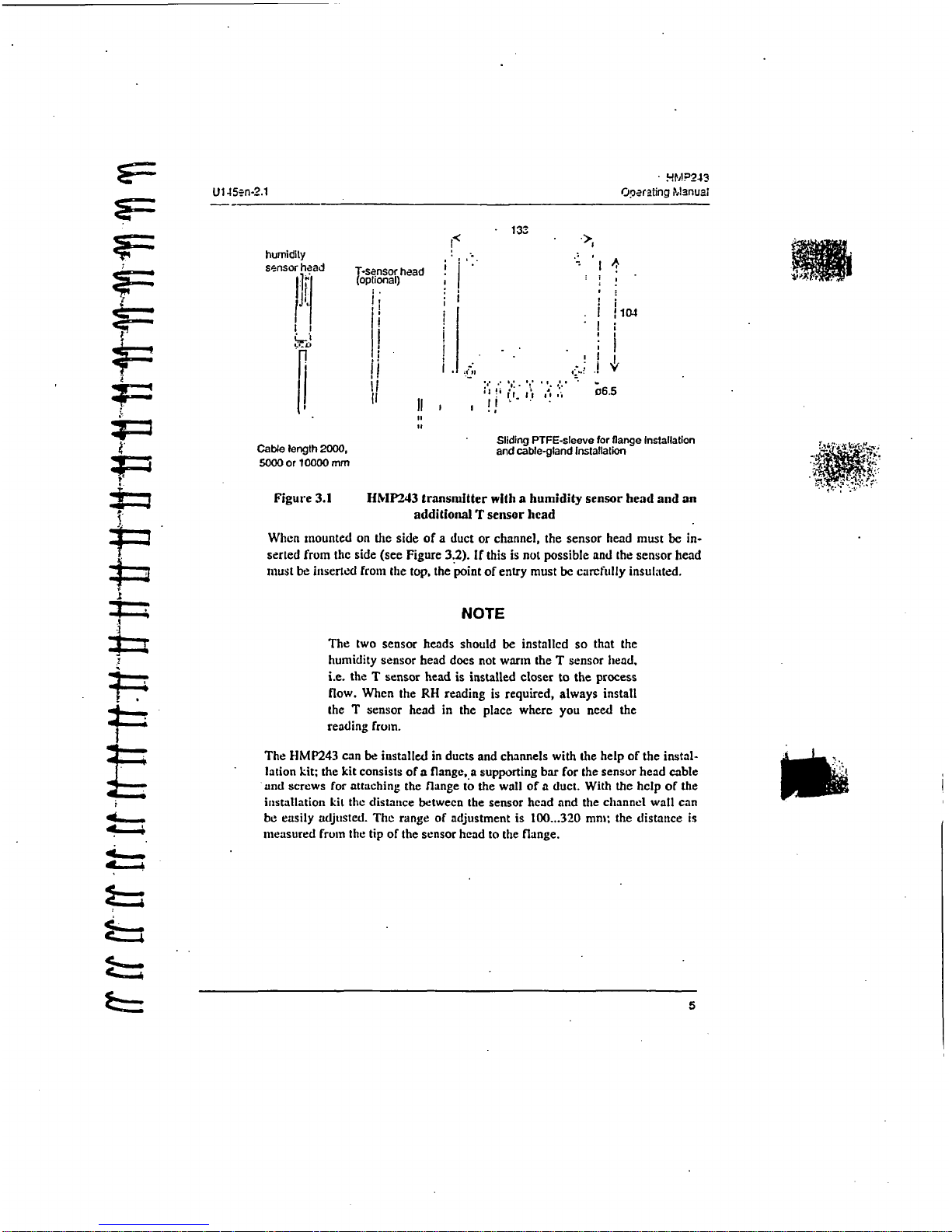
Figure
3.1
HMP243
transmitter
with a humidity
sensor
head
and
an
additional
T
sensor
head
When
mounted
on
the
side
of a duct
or
channel,
the
sensor
head
must
be
in-
serted from
the
side
(see
Figure
3.2).
If
this
is
not
possible
and the
sensor
head
must
be
inserted
from
the
top,
the
point
of
entry
must
be
carefully
insulated.
NOTE
The
two
sensor
heads
should
be
installed
so
that
the
humidity
sensor
head does
not warm
the
T
sensor
head.
i.e.
the T sensor
head
is
installed
closer
to
the
process
flow.
When
the
RH
reading
is
required,
always install
the
T
sensor
head
in
the
place
where
you
need
the
reading
from.
The
HMP243
can be
installed
in
ducts
and
channels
with
the
help
of
the
instal-
lation
kit;
the kit consists
of a flange,.a
supporting
bar
for
the
sensor
head
cable
and screws
for
attaching
the
flange
to the
wall
of a duct.
With
the
help
of
the
installation
kit
the
distance
between
the
sensor
head
and
the
channel
wall
can
be
easily
adjusted.
The
range
of
adjustment is
100...320 mm;
the
distance
is
measured
from
the
tip
of
the
sensor
head
to
the
flange.
5
HMP243
Operawing
Manual
U145an-2.1
"'(1 " < ""
duct
wall
sealing
(silicone).-
....
lange
humidity
sensor
head
/
supporting
bar
a
plugged
hole
for
reference
measurements
T-sensor
head
(optional)
PTFE
sleeve
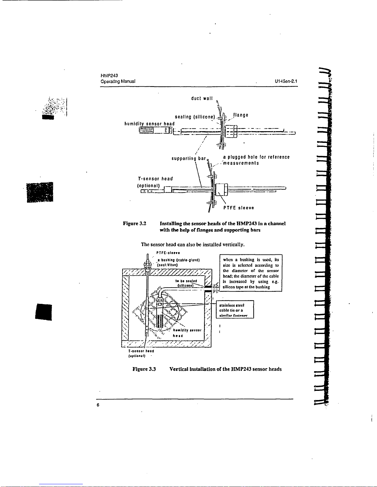
Figure
3.2
Installing
the
sensor
heads
or
the
HMP243
li a channel
with
the
help
of
flanges
and
supporting
bars
The
sensor
head can
also
be
installed
vertically.
7--
PTFE-sleve
when a bushing
is
used,
its
size
is
selected according
to
the
diameter
of
the sensor
head;
the
diameter
of
the cable
is
increased
by
using
e.g.
.
silicon tape
at
the
bushing
stainless
steel
cable tic
or
a
[
imilnr
filo.""
I~
T.sensof
head
(optonal)
Figure
3.3
Vertical Installation
of
the
HMP243
sensor
heads
6
S7-
*7'
HNIPi243
NOTE
During
installation
the
sensor
head
must
not
be
unsol-
dered
fronm
and
then
resoldered
to
the
main
printed
board
of
the
transmitter.
This
procedure
may
interfere
with
the
humidity
calibration
of
the
transmitter.
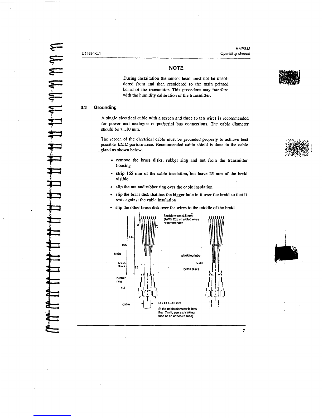
3.2
Grounding
A
single
electrical
cable
with
a
screen
and
three
to
ten wires
is
recommended
for
power
and
analogue
output/serial
bus
connections.
The
cable
diameter
should
be 7...
10
man.
The
screen
of
the
electrical
cable
must
be
grounded
properly
to
achieve
best
possible
W2MC
performance.
Recommended
cable
shield
is
done
in
the
cable
gland
as
shown
below.
"
remove
the
brass
disks,
rubber
ring
and
nut
from
the
transmitter
housing
*
strip
165
mm
of
the
cable
insulation,
but leave
25
mm
of
the
braid
visible
•
slip
the
nut
and
rubber
ring
over
the
cable
insulation
•
slip
the
brass
disk
that
has
the bigger
hole
in
it
over
the
braid so
that
it
rests
against
the
cable
insulation
"
slip
the
other
brass
disk
over
the
wires
to
the
middle
of
the
braid
.... i?
4~
~.
a
a
a
a
a
H
braid
flexible
wires
0.5 mm
(AWG
20),
stranded
wires
recommended
shiedn
tube
braid
brass
disks
DO7...10
mm
Of
the
cable
diameter
is
less
0thn
7mm,
use
a
shrinking
tube
or
an
adhesive
tape)
7
7
HMP243
Op-.rating
PlAnual
U145en-2..
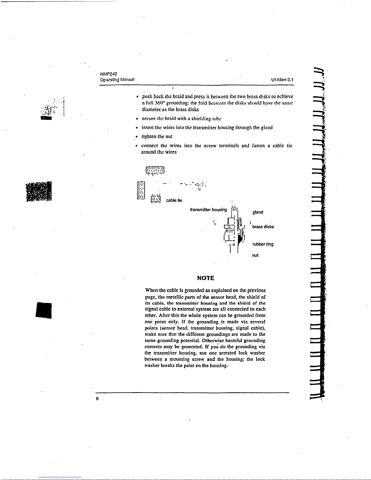
"
push
back
the
braid
and
press
it
between
the
two
brass
disks
to
achieve
a
full
360*
grounding;
the
fold
betweea
the
disks
should
have
the
saute
diameter
as
the
brass
disks
"
secure
the
braid
with
a
shielding,
tube
insert
the
wires into
the
transmitter
housing
through
the
gland
"
tighten
the
nut
*
connect
the
wires
into
the
screw
terminals and
fasten
a
cable
tie
around
the wires
lI17
cable tie
transmitter
housing
gland
--
brass
disks
-L
rubber
ring
nut
NOTE
When
the
cable
is
grounded
as
explained
on
the
previous
page,
the
metallic
parts
of
the
sensor
head, the
shield
of
its
cable,
the
transmitter
housing
and the
shield
of
the
signal cable
to
external
system
are
all
connected
to
each
other.
After
this
the whole
system
can
be
grounded
from
one
point
only.
If
the
grounding
is
made
via
several
points
(sensor
head,
transmitter
housing,
signal
cable).
make
sure
that
the
different
groundings
are
made
to
the
same grounding
potential.
Otherwise
harmful
grounding
currents
may
begenerated.
If
you
do
the
grounding
via
the
transmitter
housing,
use
one
serrated
lock
washer
between
a mounting screw
and
the
housing.
the
lock
washer
breaks
the
paint
on
the
housing.
8iI
HMP243
U
145en-2.1
Operaling
Manual
a
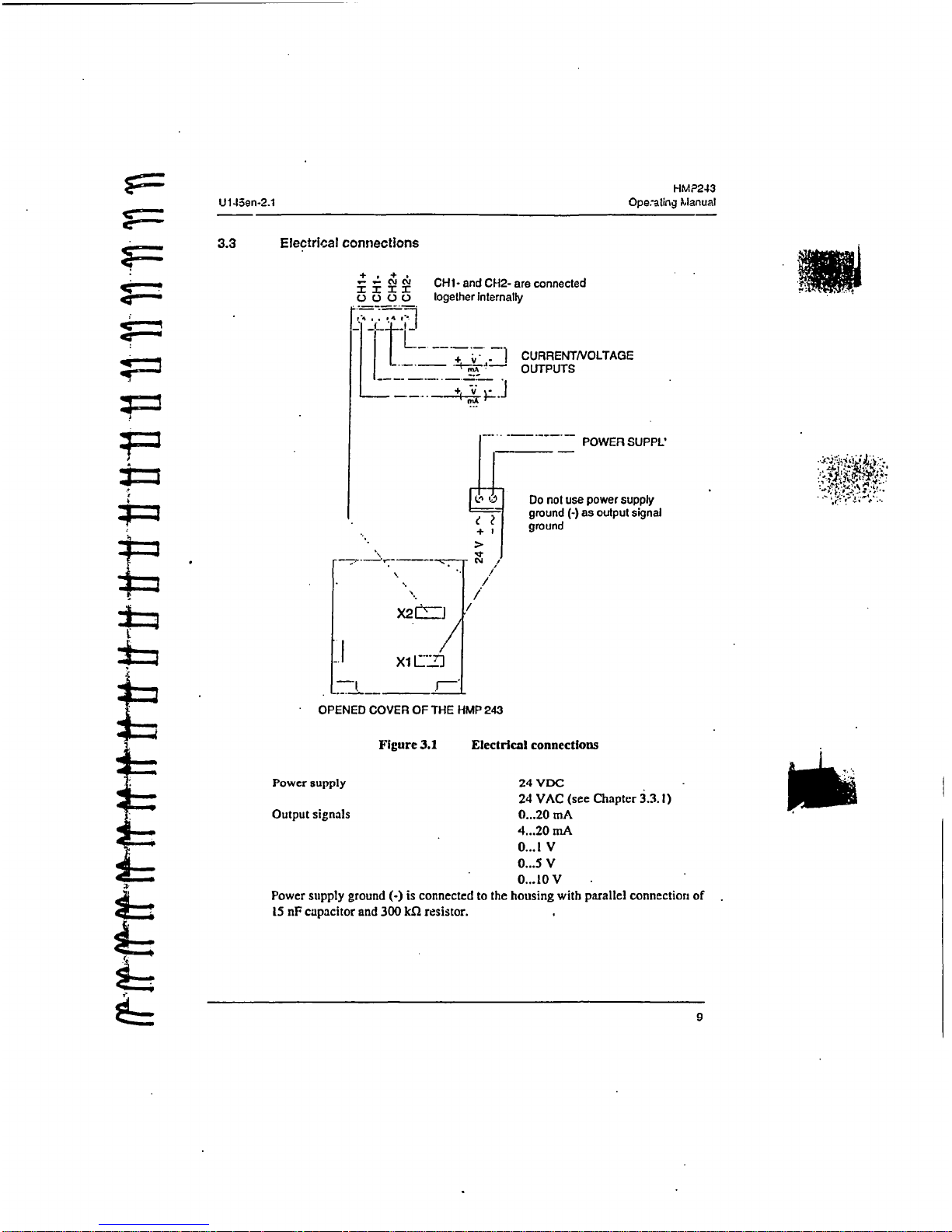
3.3
Electrical
connections
c+
J
CHI-
and
CH2-
are
connected
.)
O
t
Iogether
Internally
Lt
"1
CURRENTNVOLTAGE
*--~*--~
OUTPUTS
POWER
SUPPL'
L
Do
not
use
power supply
e
ground
(-)
as
output
signal
+
ground
C>
°/:
i/
'/
*1~
X2t~
XI
CL7]
--
t
_
r--1
OPENED
COVER
OF
THE
HMP
243
Figure
3.1
Electrical
connections
Power
supply
Output
signals
24
VDC
24
VAC
(see
Chapter
3.3.
1)
0...20
mA
4...20
mA
0...
1 V
0...5
V
0...
10V
Power
supply
ground
(-)
is
connected
to
the
housing
with
parallel
connection
of
15
nF
capacitor
and
300
kfl
resistor.
9
j;P,•,.,.!
,g
Minual
U145sn-2.1
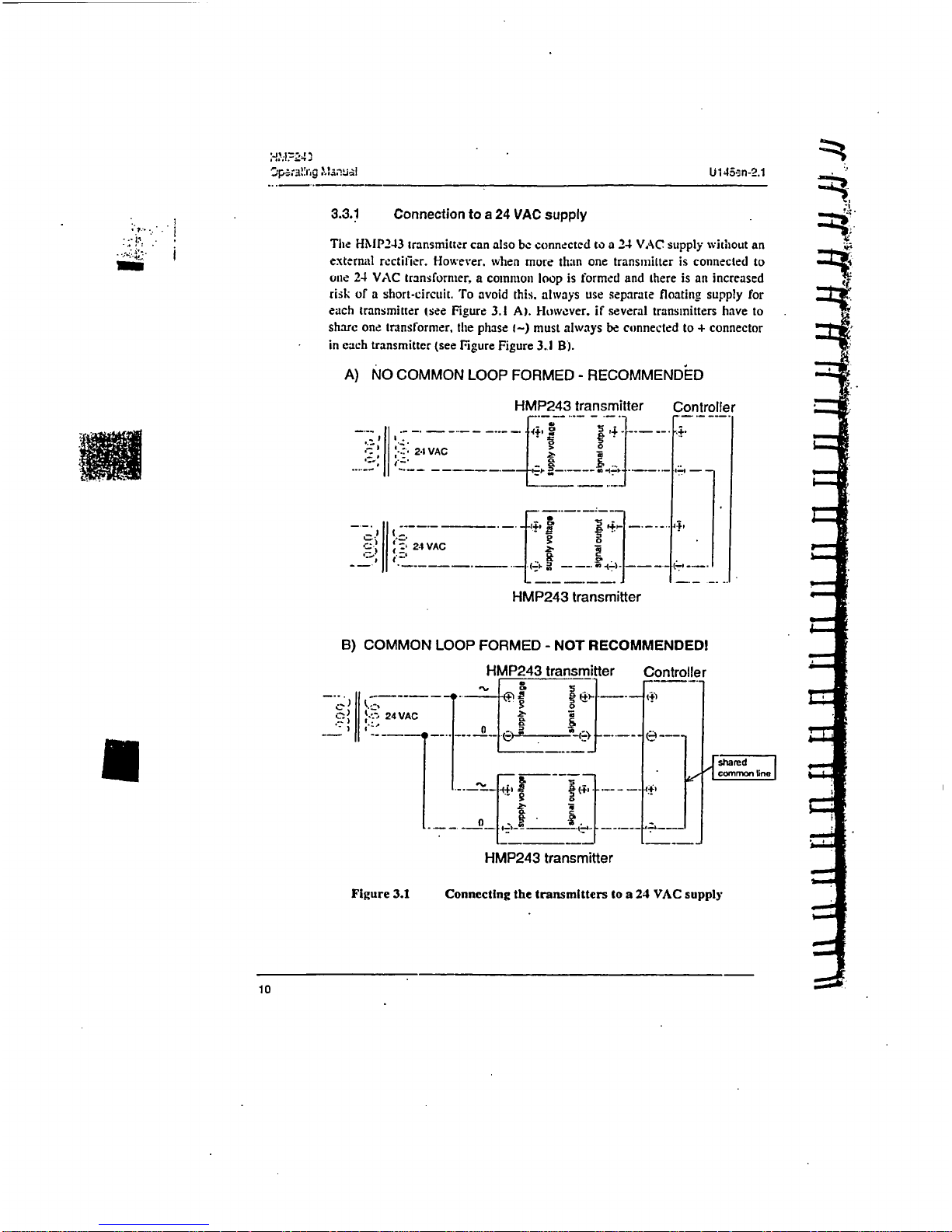
3.3.1
Connection
to a 24
VAC
supply
The
HIMP243
transmitter
can
also
be
connected
to a 24
VAC
supply
without
an
external
rectifier.
However.
when
more
than
one
transmitter
is
connected
to
one
24
VAC
transformer,
a
common
loop
is
formed
and
there is
an increased
risk
of
a
short-circuit.
To
avoid
this, always
use
separate
floating supply
for
each
transmitter
(see
Figure
3.1
A).
However,
if
several
transmitters
have
to
share
one
transformer,
the phase
t-)
must
always
be
connected
to
+
connector
in
each
transmitter
(see
Figure
Figure
3.A
B).
A)
NO COMMON
LOOP
FORMED
-
RECOMMENDED
HMP243
transmitter
Controller
-", -
*-
...
24
VAC
I
I
.....
-.
-LI-..
,
HMP243
transmitter
B)
COMMON
LOOP
FORMED
-
NOT
RECOMMENDED!
HMP243
transmitter
Controller
24VAC
"
--- -
--
e
~m•
sh~ared
_____
~common
ln
HMP243
transmitter
Figure
3.1
Connecting
the
transmitters
to a 24
VAC
supply
10
~H,'.lP24S
U145an-2..
Operating
Mlanual
4.
COMMISSIONING
_ _When
the
HMP243
transmitter
leaves
the
factory,
its
measurement
ranges
and
output
signals
have
already
been
scaled
according
to
the
order
form
completed
•-by
the
customer.
The
unit
is
calibrated
at
the
factory
and
ready
to operate
when
the
power
is
turned
on.
If
you take
into
use
active
current, voltage
or
serial bus
outputs,
make
these
connections
first:
appendix
9
describes
them
in
detail.
NOTE
Make sure
that
(lie
power
is
itot
turned
uu
unttil
cables
have been
connected
to
screw terminals!
In
transmitters
with
display,
the
software
version appears
for a few
seconds
Swhen
the
power
is
turned
on.
After
this,
measurement
results
appear
automatically.
Should
an
error
message
appear
on
the
display,
consult
Appendix
6.
-'If
your transmitter
has
a
blank
cover
and
the
LED
indicator
inside
the
housing
lights
up,
consult
Appendix
6
for further
information.
• "
Appendix
7
contains
information
on
how
to
determine
the
ranges
for alarm
outputs
and
alarm
controls
when an
alarm output
unit
is
used.
4.1
Changing
the
parameters
If
necessary,
the
user
can
subsequently change
the
measurement
units
between
metric
and
non-metric
and
select
and
scale
the
output
signals
with
software
functions.
This
is
done
through
commands,
either
utilizing
the
menus
on
the
local
display
or
giving commands
through
the serial
interface
(see
Appendices).
Most
often
the
commands
are
used
to
change
the
settings
of
the
two
analogue channels.
A'limited
range
of
commands can
be
given
with
the
three
press
switches
(up.
down,
enter)
inside
the
transmitter housing.
There
are
four
LEDs
to indicate
the
commands given
with
the
up
*and
down
switches.
All
HMP243 units
incorporate
these
switches
and
LED
indicators.
LED
commands
can be
used
to
calibrate
the
transmitters
(both
humidity
and temperature)
or
to
calibrate
the
analogue
outputs.
If
you
need
to
change
some
functions,
read
the
following
chapters carefully.
HMP243
Operating
Manual
U145-en-2.1
* I
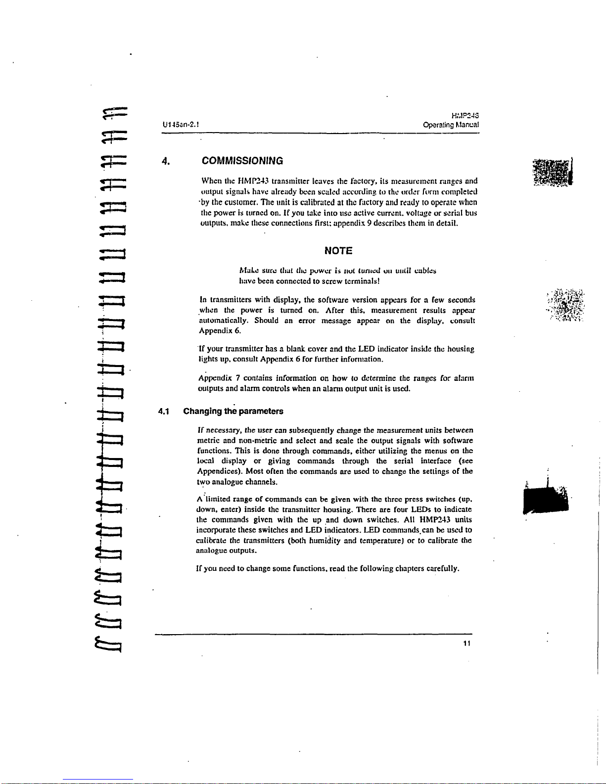
4.2
Security
lock
jumper
Before
the
s,.ttings
can
bc
changed.
thc
szcurity
lock
jumper
ia
connector
X15
must
be
removed
(see Figure
4.11.
The
security
lock
jumnper
makes
it
impossible
to
change
the
transmitter
settings
by mistake.
Ii' I°' - - - i "
*
'tI
~I
|
9'
CHANGE
OF
SETTINGS
DISABLED
]1
OPENED
COVER
OF
THE
HMP
2
Figure
4.1
Location
of
the
security
lock
Jumper
When
the
security
lock
jumper is
connected,
some
commands
are
not
available
(see
Chapter
5).
Should
the
application
require variables
that
are
not
included
in
thne
configuration
of
the
transmitter,
the
user
is
invited
to
contact
Vaisala
or
a
Vaisala
representative.
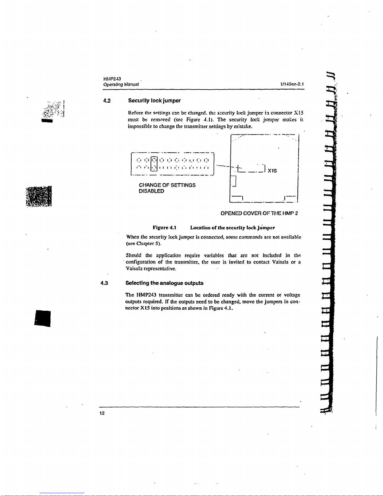
4.3
Selecting
the
analogue
outputs
The
HMP243
transmitter
can
be
ordered
ready with
the current or
voltage
outputs required.
If
the outputs
need to
be
changed,
move the
jumpers
in
con-
nector
XI5
into
positions
as
shown in
Figure
4.1.
I'mo
12
HMP243
U145an-2.1
Operating
Manual
-
CHI
CH2
N
CHI
CH2
SCHI
CH-2
oC.)
r__1_l----
13
WiF1FiFIF11
SCHI
CH2
o
C__1
o.'
C
o
1'
W
i
L
I
`,*
2
.
J
I
CURREtNT
OUTPUTS
0...
201/4...20
mA
VOLTAGE
OUTPUTS
0...5VI0...
1OV
VOLTAGE
OUTPUTS
0...
1V
CHI
0... 1 VOLTAGE
OUTPUT
CH2
CURRENT OUTPUT
X115
OPENED
COVER
OF
THE
HMP
24
Figure
4.1
Selecting the
analogue
outputs
with
jumpers
The
software
has
to
bc
inforried
which
outputs
are
in use. This
is
done
either
through
the
serial interface
or
'the menus
on a local
display.
The serial
,ommand
is
AMODE
and
the
display/keypad command
'Mode
c"
Analog
outputs
-L
Mode'
(see
Chapter 5).
For
the
scaling
of
the
outputs,
see
serial command
ASCL
and
the
display
command
'Mode
c' Analog
outputs * Scale%.
All
the
jumpers
are
used
only
with
the
0... t V
outputs.
When
other
outputs
are
in
use,
the
spare
jumpers
are
kept
in
connector
X55.
t
13
HMP243
Operating
Manual
U145on-2.1
MOWN
[~X55
J
spare
jumpers
"-'1
r-..
F-
OPENED
COVER
OF
THE
HMP
243
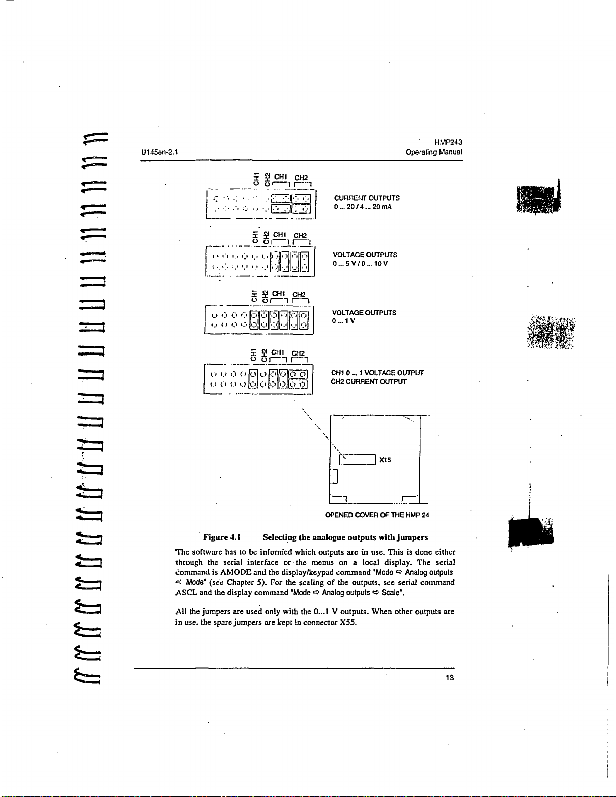
Figure
4.2
Spare
jumpers
4.4
Connecting
the
RS
232C
serial
bus
OPENED
COVER
OF
THE
HMF
Figure
4.1
Serial
bus
connections
To
connect
a
PC
to
the
HMP243
transmitter
via
the
RS
232C
serial
bus,
one
of
the
following
cables
is
required.
The
type
of
the
cable
depends
on
the
terminal
and the
connector
type.
14
i-H%,1243
U t
45er-2.1
Oparating
Manual
3
.TXD
b
TX
75 "--
GND
61
PC
TEMHL
~P7
=- -
Gtl
DIS
2
-
XDI
RX
HMP243
5.5
TERMINAL
D25P
7
-
GHD
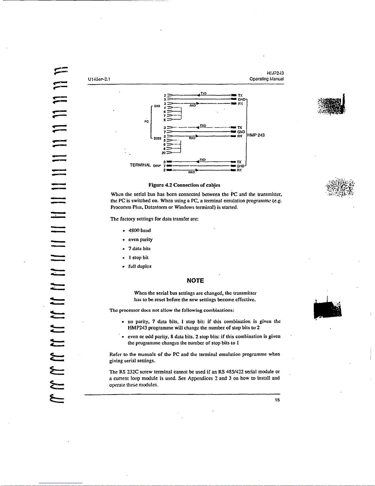
Figure
4.2
Connection
of cables
When
the
serial
bus
has
been connected
between the
PC
and
the
transmitter,
the
PC
is
switched
on.
When
using a PC, a terminal emulation programme
(e.g.
Procomm Plus,
Datastorm
or
Windows
terminal)
is
started.
-
The factory
settings
for
data
transfer
are:
•#
4800
baud
*
even
parity
-7 data
bits
- I
stop
bit
-
full
duplex
NOTE
When
the
serial
bus
settings
are
changed,
the transmitter
4-
has
to
be
reset
before
the
new
settings
become cffcctive.
_Thc
processor
does
not
allow
the
following
combinations:
-
no
parity,
7
data
bits, I stop
bit:
if
this
combination
is given the
~HMP243
programme
will
change
the number
of
stop bits
to
2
-
even
or odd
parity, 8 data
bits, 2 stop
bits:
if
this
combination
is
given
the
programme
changes
the
number
of
stop
bits to
I
*-
Refer
to
the
manuals
of
the
PC
and
the
terminal
emulation
programme
when
giving
serial settings.
The
RS
232C
screw
terminal
cannot
be
used
if
an
RS
485/422
serial
module
or
a current
loop module
is
used.
See
Appendices 2 and 3 on how
to
install
and
operate
these
modules.
15
-7
i•:;.:J
t'-.i::U145.a-.-2.'!
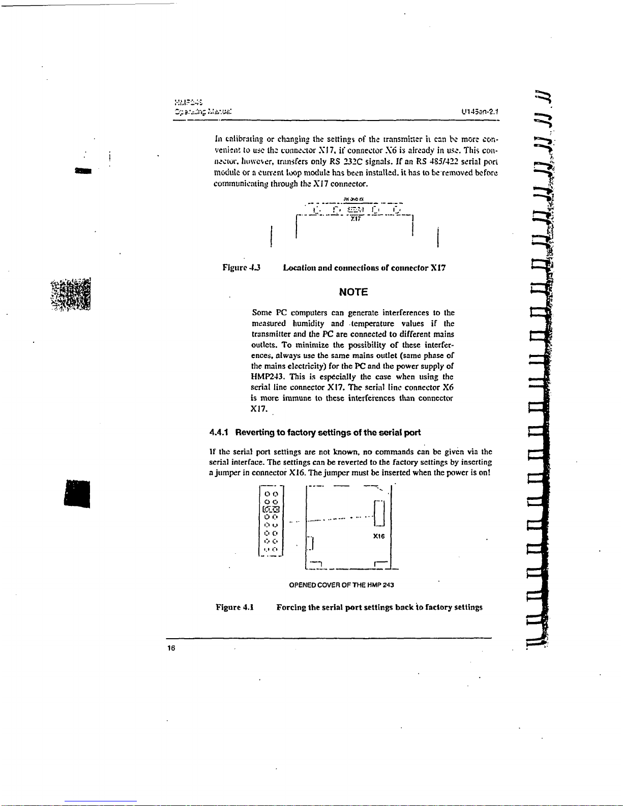
In
calibrafin2
or
changing
the
settings
of
the
transminter
it
can
be
more con-
venient
to
use
the
connector
XN
7.
if
connector
X6
is
already
in
use.
This
coil-
hector.
huwcrer,
transfers
only
RS
232C
signals.
If
an
RS
485/422
serial
port
module
or a current
loop module
has
been
installed,
it
has
to
be
removed before
communicating
through
the
XI 7 connector.
Figure
4.3
Location
and connections
of
connector
XI7
NOTE
Some
PC
computers
can
generate
interferences
to
the
measured
humidity
and
temperature
values
if
the
transmitter
and
the
PC
are
connected
to
different
mains
outlets.
To
minimize
the
possibility
of
these
interfer-
ences,
always
use
the
same
mains
outlet
(same
phase
of
the
mains
electricity)
for
the
PC
and
the
power
supply
of
HMP243.
This
is
especially
the
case
when
using
the
serial
line
connector
X17.
The serial
line
connector
X6
is
more
immune
to these
interferences
than
connector
Xl7.
4.4.1
Reverting
to
factory
settings
of
the serial
port
If
the
serial port
settings
are
not
known,
no
commands
can be
given
via
the
serial
interface.
The
settings
can be
reverted
to
the
factory
settings
by
inserting
a
jumper
in
connector
X16.
The
jumper
must
be
inserted
when
the power
is
on!
O00
NG
0
C, .
.
____I
.f
OPENED
COVER
OF
THE
HMP
243
Figure
4.1
Forcing
the
serial
port
settings
back
to
factory
settings
16

~HMdF24•3
U
145en-2.1
,O1eirg
ManLe,
When
the
juniper
is
in;.±rted the
serial
line factory
settings
become valid,
but
itily
iemp.'ura'ily.
'1rhe
tr-ansmltter
muast
be
given
new
setting3:
otherwise
the."
transmitter
aues
the
old.
unknown
settings
after
power-up.
WVhe.n
the
new
-settings
have
been
given,
the
transmitter
must
be
reset.
The
jumper
must
by
removed
before
the
transmitter
is
reset;
if
the
jumper
is
in
place
when
power
is
_turned
on.
the
transmitter
does
not
work.
After
jumper
insertion
the
transmitter
is
in
STOP
mtde.
ready
to
receive
S¢colnniands.
The
same
method
is
used
when the
transmitter
is
in
POLL
mode
and
the
user
has
forgaotten
its
address.
-
CAUTIONý
Inserting
a
jumper
in
any
other place
in
connector
X16
voids
the
guarantee
of
the
transmitter.
17
HMP243
Operating
Manual
U!45en-2.1
5.
COMMANDS
_
As
the
HIMP243
transmitter
is a microprocessor
based
device,
its
configuration
can
be
set
to
correspond
to
the
specific
needs
of
thc
user.
This
is
done through
commands,
either
by
utilizing
the
menus
on
the
local
display
or
by
giving
commands
through
the
serial interface
(see
Appendix
1).
Most
often
the
commands
are
used
to
change the
settings
of
the two analogue
channels.
A
limited
range
of
commands
can be
given
by
using
the
three
press
switches
-
up.
down
and
enter
-
inside
the
transmitter
housing.
Four
LEDs
indicate
the
command
given
with
the
up
and
down switches.
LED
commands
can
be
used
to
calibrate
the
transmitter
(both
humidity
and
temperature)
or
to
calibrate
the
analogue
outputs.
A
full
range
of
commands
can
be
given
through
the
display/keypad
or
through
the
RS
232C
serial
bus.
The
commands
can
be
used
e.g. to
select
anti
scale
the
outputs,
to
calibrate
the
humidity
and
temperature
channels
as
well
as
the
analogue
outputs
and
to
set the
serial
interface.
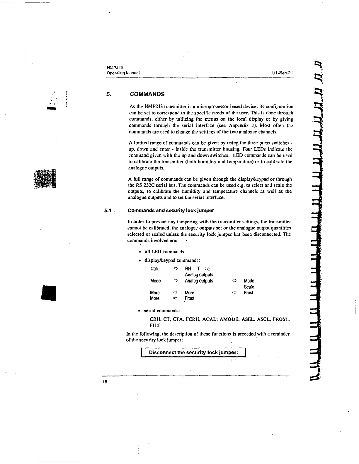
5.1
Commands and security
lock
jumper
In
order
to
prevent
any
tampering
with
the
transmitter
settings,
the
transmitter
cannot
be
calibrated,
the
analogue
outputs set or
the
analogue
output
quantities
selected
or
scaled
unless
the
security
lock
jumper
has
been
disconnected.
The
commands
involved
are:
•
all
LED commands
"
display/keypad
commands:
Cali
•
RH
T Ta
Analog
outputs
Mode
c:
Analog
outputs
•
Mode
Scale
More
cc
More
C:,
Frost
More
,
Frost
*
serial
commands:
CRH,
CT,
CTA.
FCRH,
ACAL; AMODE.
ASEL.
ASCL,
FROST.
FILT
In
the
following,
the
description
of
these
functions
is
preceded
with
a reminder
of
the
security
lock
jumper:
Disconnect
the
security
lock
jumpert
IV
FHNI24S
U145.en-2.1
Operating
',Aanuai
5.2
LED
commands
Jar
NOTE
If
the
transmitter
has a di3play/keypad
cover.
the
LED
commands cannot
be
used.
.
=.-.
LED
commands
can be used
to
operate
the
transmitter
in the
field.
These
cuminands
can
be
used
in
humidity
and
tenipcrature
calibration
and
calibration
of
tha
analogue
outputs.
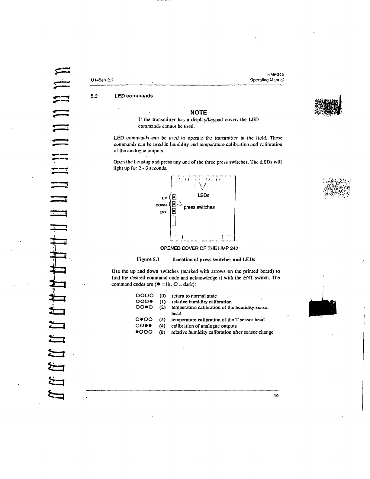
Open
the
housing and
press
any
one
of
the
three
press
switches.
hie
LEDs
will
light
up
fur
2 -3 seconds.
up
DOWN
ENT
LEDs
]"
press
switches
.-A
OPENED
COVER
OF
THE
HMP
242
Figure
5.1
Location
of
press
switches
and
LEDs
Use
the
up
and
down switches
(marked
with
arrows
on
the
printed
board)
to
find
the
desired
command
code
and acknowledge
it
with
the
ENT
switch.
The
command codes
are
(*
=
lit. 0 =
dark):
0000
0000
0000
(0)
return
to
normal
state
(1)
relative humidity
calibration
(2)
temperature
calibration
of
the
humidity
sensor
head
0000
(3)
temperature
calibration
of
the T sensor
head
0000
(4)
calibration
of
analogue
outputs
0000
(8)
relative humidity
calibration
after
sensor
change
19
HWP'24:3
Operatt.g1
Mm•'.;
U145e-r-2.1
5.3
Displaylkeypad
commands
loin
5.3.1
Display
mode
In
the
display
mode
the
transmitter
outputs
measurements
on
the
display:
dif-
.
ferent
quantities
can
be
scrolled with arrow
keys.
The first
line
is
scrolled
with
button o and
the second
line with
button
r; all selections
are
stored
with
ENTER.
The selected
quantities
appear
on
the
display also
after
power failure.
Afwtr
reset
the
transmitter
is
always
in
the
display
mode.
The
display
also
shows
error messages
and
alarms
if
they
occur.
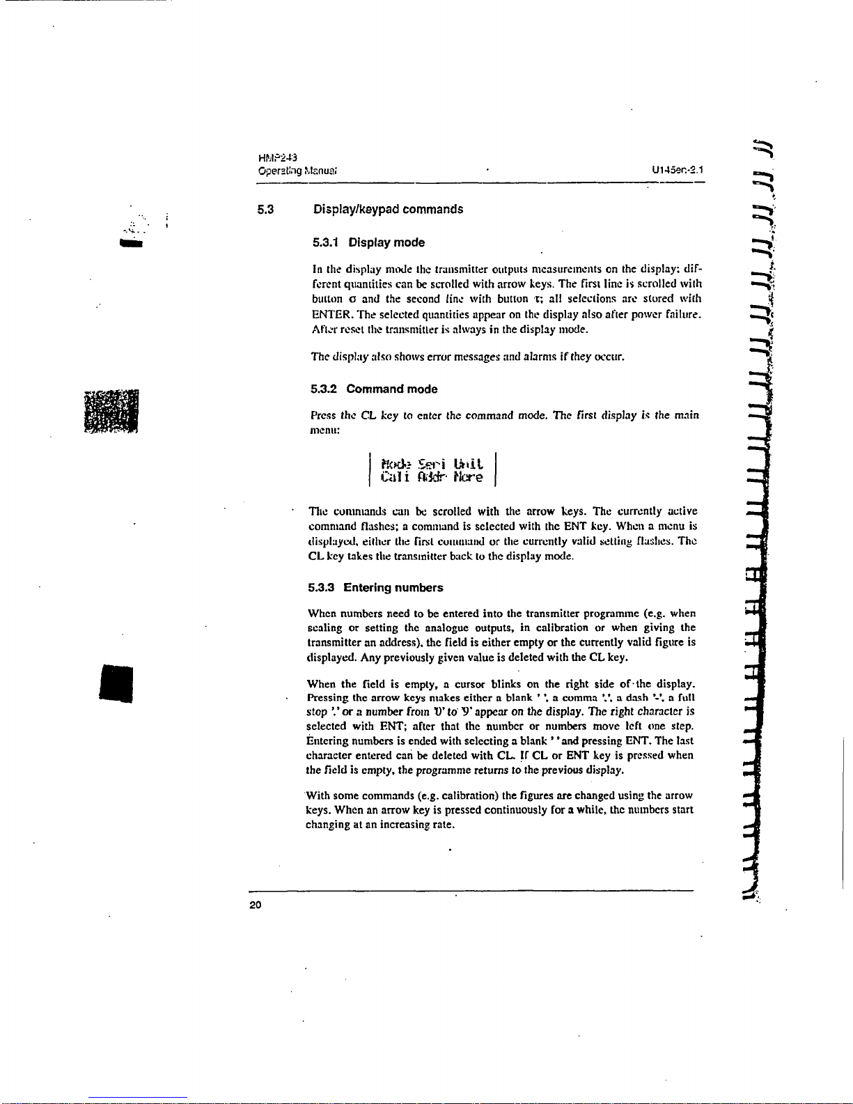
5.3.2
Command
mode
Press
the
CL
key
to
enter
the command
mode.
The
first display
is
the
main
menu:
Cali i MrV.
ttre
The
commands
can
be
scrolled
with
the arrow keys.
The
currently
active
command
flashes; a command
is
selected
with
the
ENT
key.
When a menu
is
displayed,
either
the first command
or
the
currently
valid
$etting flashes.
The
CL
key
takes
the
transmitter
back
to
the display
mode.
5.3.3
Entering
numbers
When
numbers
need
to
be
entered
into
the
transmitter
programme
(e.g.
when
scaling
or
setting
the
analogue outputs, in
calibration or
when
giving
the
transmitter
an
address),
the
field
is
either
empty
or
the
currently valid
figure
is
displayed.
Any
previously
given value
is
deleted with
the
CL
key.
When
the
field
is empty,
a
cursor
blinks
on
the right side
of
the
display.
Pressing
the arrow
keys
makes
either
a blank
' .a comma
'. a dash
'-.
a full
stop
'.'
or a number
from 0 to
'9'
appear
on
the
display.
The
right character
is
selected
with ENT; after
that the number or
numbers
move
left one
step.
Entering
numbers
is
ended
with
selecting a blank
''and
pressing
ENT.
The
last
character
entered
can
be
deleted
with
CI.,.
If
CL
or
ENT
key
is
pressed
when
the
field
is
empty,
the
programme
returns
to
the
previous
display.
With some commands
(e.g.
calibration)
the
figures are changed
using
the
arrow
keys.
When
an
arrow
key
is
pressed
continuously
for a
while,
the
numbers
start
changing
at
an
increasing
rate.
20
U',45er,.2.I
Operating
;.,t&-.'ual
e.==-=43
5.3.4
Analogue
output
commands
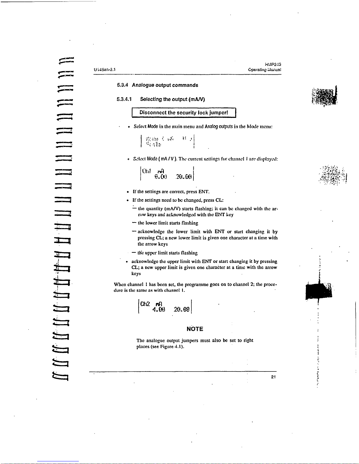
5.3.4.1
Selecting
the
output
(mAN)
Disconnect
the
security
lock
jumper!
•
Select
Mode
in
the
main
menu
and
Analog
outputs
in
the
Mode menu:
Select
Mode
(mA/V
).
The
current settings
ftr
chaimnl I are
displayed:
*
If
the
settings
are
correct,
press
ENT.
.
If
the
settings
need
to
be
changed,
press
CL:
-
the
quantity
(mA/V)
starts
flashing;
it
can
be
changed
with
the
ar-
row
keys
and
acknowledged
with
the ENT
key
-
the
lower
limit starts flashing
-
acknowledge
the
lower
limit
with
ENT
or
start
changing
it
by
_ _pressing
CL;
a
new
lower
limit
is
given one
character
at a time
with
the arrow keys
--
the
upper
limit starts
flashing
*
acknowledge
the
upper
limit with
ENT
or
start
changing
it
by
pressing
CL; a
new
upper
limit
is
given
one
character
at a
time
with
the
arrow
keys
When
channel
I
has
been set, the
programme goes
on
to
channel
2;
the
procc-
dure
is
the
same
as
with channel
I.
Ch2
MA
NOTE
The analogue
output
jumpers
must
also
be
set
to
right
places
(see
Figure
4.
1).
21
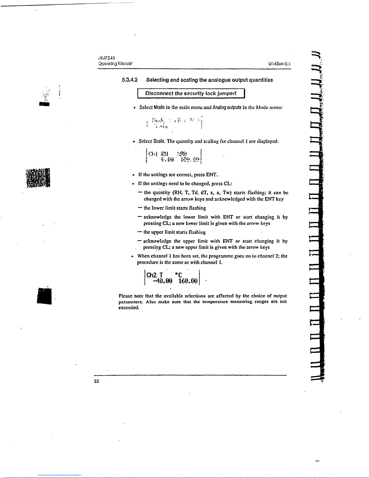
5.3.4.2
Selecting
and scaling
the
analogue
output
quantities.
Disconnect
the
security
lock
juniper.
a
Select
Mode
in
the
main menu
and
Analog
outputs
in
the
Mode
menu:
Select
Scale.
The
quantity
and
scaling for
channel I are
displayed:
"
If
the
settings
are
correct,
press ENT.
-
If
the
settings
need
to
be
changed,
press
CL:
-
the quantity
(RH,
T, Td,
dT,
x,
a,
Tw)
starts
flashing:
it
can
be
changed
with
the
arrow
keys
and
acknowledged
with
the ENT
key
-
the
lower
limit
starts
flashing
-
--
acknowledge
the
lower
limit
with
ENT
or start
changing
it
by
pressing
CL;
a
new
lower
limit
is
given
with
the
arrow
keys
-
the
upper
limit
starts
flashing
-
acknowledge
the upper
limit
with
ENT
or
start changing
it
by
pressing
CL; a new
upper
limit
is given
with
the
arrow
keys
*
When
channel
I
has
been
set.
the
programme
goes
on
to
channel
2;
the
procedure
is
the
same
as
with
channel
1.
--
40.N
16•.
O0
U
.
Please
note that the available
selections
are
affected
by
the choice
of
output
parameters.
Also
make
sure
that the
temperature
measuring
ranges
are
not
exceeded.
22
Hr.-!I P2an
La
5.3.5
Output
via
the
serial
bu.
5.3.5.1
Turning
the
serial
Interface
echo
ON/OFF
Select
More
in
the
main
menu.
select
More
in
the
More
ne:nu
and
•elect
-.
Echo
in
the
second
More
menu.
*
Use
the
arrow
keys
to
select
the
righi
alternative
and
press
ENT.
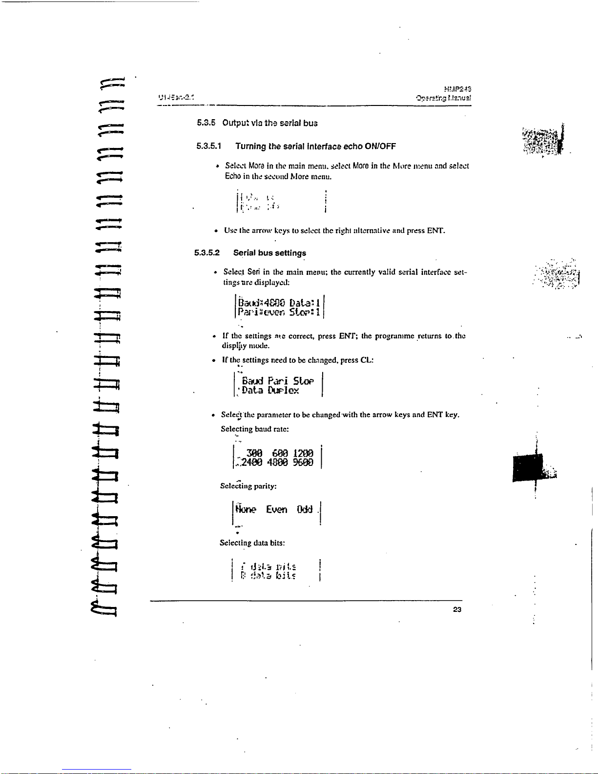
5.3.5.2
Serial
bus
settings
'
-
-Selec.t
Seri
in
the
main
menu;
the
currently
valid
serial
interface
set-
.
lings
ure
displayed:
ZP
.="4:-.•r
ZLOP
1
,:
__
i
I
___
If
the
settings
ate
correct,
press
ENT;
the
programme
.returns
to.the
display
mode.
.
If
the
settings
need
to
be
changed,
press
CL:
"B6-
Pari
RLoe
..
'
Data
I
I
lex
Seleiitthe
parameter
to
be
changed
with
the
arrow
keys
and
ENT
key.
Selecting
baud
rate:
4800
9600
Seleýting
parity:
hoe
Even,
OMd
Selecting
data
bits:
23
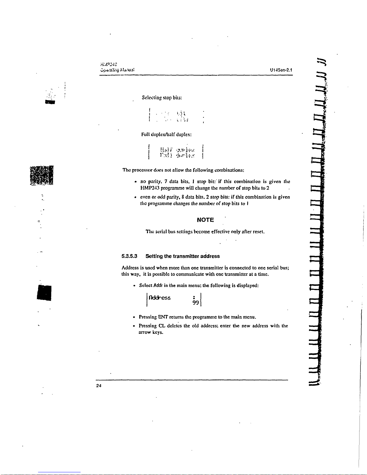
Selecting
stop
biti:
Full
duplex/half
duplex:
The
processor
does
not
allow
the
following combinations:
-
no
parity, 7 data
bits, I
stop
bit:'if
this
combination
is
given
the
HMP243
programme
will
change
the
number
of
stop
bits
to
2
#
even
or
odd
parity,
8
data
bits.
2
stop
bits:
if
this
combination
is
given
the
programme
changes
the
number
of
stop
bits
to
I
NOTE
The
serial
bus
settings
become
effective
only
after reset.
5.3.5.3
Setting
the
transmitter
address
Address
is
used
when more
than
one
transmitter
is
connected
to
one
serial
bus;
this
way,
it
is
possible
to communicate
with
one'transmitter
at
a
time.
.
Select
Addr
in
the main
menu:
the
following
is
displayed:
99
Pressing
ENT
returns
the
programme
to
the
main
menu.
o
Pressing
CL deletes
the old
address;
enter
the
new
address
with
the
arrow
keys.
 Loading...