

Page 1

HMP230 Series Transmitters
USER'S GUIDE
M210225en-B
May 2002
Page 2

PUBLISHED BY
Vaisala Oyj Phone : (+358 9) 894 91
P.O. Box 26 Fax: (+358 9) 8949 2227
FIN-00421 Helsinki
Finland
Visit our Internet pages at http://www.vaisala.com/
© Vaisala 2002
No part of this manual may be reproduced in any form or by any
means, electronic or mechanical (including photocopying), nor may its
contents be communicated to a third party without prior written
permission of the copyright holder.
The contents are subject to change without prior notice.
Page 3

HMP230 SERIES
M210225en-B User's Guide
Contents
1. PRODUCT DESCRIPTION................................................................................................... 1
2. TO BE NOTED WHEN MEASURING HUMIDITY.................................................................. 3
3. INSTALLATION ................................................................................................................... 4
3.1. Selecting the place of installation .......................................................................... 4
3.2. Mounting ................................................................................................................. 5
3.2.1. Mounting the HMP231................................................................................ 5
3.2.2. Installing the HMP233, HMP234 and HMP235............................................ 5
3.2.3. HMP233 transmitter...................................................................................6
3.2.4. HMP234 transmitter...................................................................................7
3.2.5. HMP235 transmitter................................................................................. 10
3.2.6. HMP237 transmitter................................................................................. 11
3.2.7. HMP238 transmitter................................................................................. 12
3.2.7.1. Mounting; overview.................................................................................. 13
3.2.7.2. Installing the probe through the ball valve assembly................................. 16
3.3. Grounding ............................................................................................................. 20
3.4. Electrical connections .......................................................................................... 22
3.4.1. Connection to a 24 VAC supply ................................................................ 23
4. COMMISSIONING.............................................................................................................. 24
4.1. Changing the parameters ..................................................................................... 24
4.2. Security lock jumper............................................................................................. 24
4.3. Selecting the analogue outputs ........................................................................... 25
4.4. Connecting the RS 232C serial bus...................................................................... 27
4.4.1. Reverting to factory settings of the serial port........................................... 29
5. CONNECTION TO PC ........................................................................................................ 31
5.1. Giving the communication parameters ................................................................ 31
6. COMMANDS...................................................................................................................... 34
6.1. Commands and security lock jumper .................................................................. 34
6.2. LED commands..................................................................................................... 35
6.3. Display/keypad commands ................................................................................... 36
6.3.1. Display mode...........................................................................................36
6.3.2. Command mode ...................................................................................... 36
6.3.3. Entering numbers..................................................................................... 36
6.3.4. Analogue output commands..................................................................... 37
6.3.4.1. Selecting the output (mA/V) ..................................................................... 37
6.3.4.2. Selecting and scaling the analogue output quantities ............................... 38
6.3.5. Output via the serial bus .......................................................................... 39
6.3.5.1. Turning the serial interface echo ON/OFF................................................ 39
6.3.5.2. Serial bus settings.................................................................................... 39
6.3.5.3. Setting the transmitter address ................................................................ 40
6.3.5.4. Selecting the output units......................................................................... 41
6.3.5.5. Selecting the calculation mode ................................................................. 41
6.3.6. Output modes .......................................................................................... 41
6.3.6.1. Setting the serial interface operation mode .............................................. 42
6.3.7. Others...................................................................................................... 43
6.3.7.1. Setting the averaging time........................................................................ 43
i
Page 4

HMP230 SERIES
User's Guide M210225en-B
6.3.7.2. Setting the pressure for pressure compenstion of the HUMICAP sensor
and for mixing ratio, wet bulb and enthalpy calculations........................43
6.3.7.3. Setting the date........................................................................................ 44
6.3.7.4. Setting the time........................................................................................ 44
6.4. Serial commands...................................................................................................46
6.4.1. Analogue output commands .....................................................................46
6.4.1.1. Setting the analogue outputs ....................................................................46
6.4.1.2. Selecting and scaling the analogue output quantities................................47
6.4.1.3. Scaling the analogue outputs....................................................................47
6.4.2. Output via the serial bus...........................................................................48
6.4.2.1. Starting the measurement output..............................................................48
6.4.2.2. Stopping the measurement output............................................................48
6.4.2.3. Outputting the reading once...................................................................... 48
6.4.2.4. Setting the output interval for the RUN mode ............................................49
6.4.2.5. Serial bus settings....................................................................................49
6.4.2.6. Selecting the output units .........................................................................50
6.4.2.7. Setting the averaging time........................................................................50
6.4.2.8. Setting the transmitter address.................................................................50
6.4.2.9. Setting the calculation mode.....................................................................51
6.4.2.10. Resetting the transmitter ..........................................................................51
6.4.3. Operating the transmitter via the serial bus...............................................51
6.4.3.1. Setting the serial interface........................................................................51
6.4.3.2. OPEN & CLOSE.......................................................................................52
7. CALIBRATION ...................................................................................................................53
7.1. Humidity calibration.............................................................................................. 53
7.1.1. One point calibration procedure ................................................................54
7.1.1.1. With serial commands..............................................................................54
7.1.1.2. With display/keypad commands................................................................55
7.1.1.3. With LED commands ................................................................................55
7.1.2. Two point calibration procedure ................................................................55
7.1.2.1. With serial commands..............................................................................56
7.1.2.2. With display/keypad commands................................................................56
7.1.2.3. With LED commands ................................................................................57
7.1.3. Calibration procedure after sensor change ...............................................57
7.1.3.1. With serial commands..............................................................................57
7.1.3.2. With display/keypad commands................................................................58
7.1.3.3. With LED commands ................................................................................58
7.1.4. Humidity calibration table..........................................................................59
7.2. Temperature calibration........................................................................................60
7.2.1. One point offset correction .......................................................................60
7.2.1.1. With serial commands..............................................................................60
7.2.1.2. With display/keypad commands................................................................61
7.2.1.3. With LED commands ................................................................................61
7.2.2. Two point temperature calibration.............................................................62
7.2.2.1. With serial commands..............................................................................62
7.2.2.2. With display/keypad commands................................................................62
7.2.2.3. With LED commands ................................................................................63
7.3. Calibration of the analogue outputs .....................................................................63
7.3.1. With serial commands..............................................................................63
7.3.2. With display/keypad commands................................................................64
7.3.3. With LED commands ................................................................................64
8. MAINTENANCE..................................................................................................................66
8.1. Reference measurements ..................................................................................... 66
8.2. Self-diagnostics.....................................................................................................66
8.3. Changing the HUMICAP® sensor and the filter ................................................... 67
ii
Page 5

HMP230 SERIES
M210225en-B User's Guide
8.4. Temperature channel adjustment with Pt 100 simulators................................... 67
8.4.1. Adjustment using serial commands.......................................................... 67
8.4.2. Adjustment using display commands........................................................ 68
8.4.3. Adjustment using LED commands............................................................ 68
8.5. Measurement of output currents using test points............................................. 69
8.6. Adjusting the contrast of the display................................................................... 70
9. TECHNICAL DATA ............................................................................................................ 71
9.1. Relative humidity .................................................................................................. 71
9.2. Temperature.......................................................................................................... 71
9.3. Calculated variables ............................................................................................. 71
9.4. Pressure ................................................................................................................ 73
9.5. Analogue outputs.................................................................................................. 73
9.6. Electronics ............................................................................................................ 74
9.7. Mechanics ............................................................................................................. 75
9.8. Electromagnetic compatibility.............................................................................. 77
10. SPARE PARTS AND OPTIONS ......................................................................................... 78
11. FACTORY CALIBRATION AND REPAIR SERVICE ........................................................... 79
Appendix 1 Serial commands......................................................................................... 80
Appendix 2 Installing the power supply module ......................................................... 103
Appendix 3 Installing and using the RS 485/422 serial port module.......................... 106
Appendix 4 Installing and using the digital current loop module............................... 117
Appendix 5 Error messages.......................................................................................... 127
Appendix 6 Calculation formulas ................................................................................. 133
Appendix 7 Alarm output unit....................................................................................... 135
Appendix 8 Connectors ................................................................................................ 140
Appendix 9 Re-gaining.................................................................................................. 144
Appendix 10 Pressure conversion chart ........................................................................ 155
Appendix 11 Wiring diagramme MK4456 ....................................................................... 156
Warranty................................................................................................................................. 157
iii
Page 6

HMP230 SERIES
User's Guide M210225en-B
This page intentionally left blank.
iv
Page 7

HMP230 SERIES
M210225en-B User's Guide
1. PRODUCT DESCRIPTION
The HMP230 series transmitters are microprocessor based instruments for the
measurement of relative humidity and temperature; from these variables they
can calculate dewpoint temperature, absolute humidity, mixing ratio, wet bulb
temperature and enthalpy. The transmitters have two analogue outputs and
they can be connected to a serial bus via the RS 232C interface or through an
RS 485/422 serial module or a current loop module. At dewpoint temperatures
below 0 °C, the user can select whether the transmitter calculates dewpoint or
frostpoint reading; as default, the transmitter calculates dewpoint.
The series consists of four types of transmitters:
• HMP231, wall installation
• HMP233, ifor tight places; temperatures up to +80 or +120 °C
• HMP234, forpressure or vacuum chambers
• HMP235, for high temperatures of +180 °C
• HMP237, leak proof small size probe for pressures up to 10 bar
• HMP238, for pressurized processes
The transmitters can be configured in many ways. They can have either a
blank cover or a cover with a local display and keypad with which the user can
operate the transmitter. The power supply voltage can be selected from three
alternatives. Two analogue output signals are selected from the measured and
calculated quantities; the signals can be scaled and the measurement ranges
changed within certain limits. The HMP233, HMP234, HMP235, HMP237
and HMP238 probes can be supplied with two, five or ten metre sensor head
cable.
The humidity measuring range is 0...100 %RH. The temperature is measured
with a Pt 100 sensor. Temperature measurement range depends on the model;
the HMP234, HMP235, HMP237 and HMP238 have the widest range, -
40...+180 °C. The analogue temperature output can be scaled quite freely, for
example-20...+60 °C can be set to correspond to 0...10 V. The dewpoint
temperature, absolute humidity, mixing ratio, wet bulb temperature and
enthalpy ranges are also scalable.
In some applications the sensor gain may gradually decrease because of an
interference caused by some chemical present in the ambient. These changes
can be recovered with an optional re-gaining function. Transmitters including
this function are equipped with a composite humidity and temperature sensor.
The HMP230 series units incorporate the HUMICAP® sensor, which uses an
operating principle based on changes in the capacitance of the sensor as its
thin polymer film absorbs water molecules.
1
Page 8

HMP230 SERIES
User's Guide M210225en-B
Options
Calculation vari-
ables
dewpoint temperature, mixing ratio, absolute humidity, wet bulb temperature, enthalpy
Power supply 24 VDC (standard), (for 24 VAC, see page 23)
115/230 VAC
Serial interface RS 232C (standard), RS 485/422, current loop
Display cover cover with or without local display & keypad
Filters sintered filter, PPS grid with steel netting, PPS grid
Cable length 2, 5 or 10 metres
Alarm output unit Not with 115/230 VAC power supply and not with
HMP231
Cable connectors For 24 VDC supply, for analogue outputs, for RS
232C line and for RS 485 single loop line; see
Appendix 8 for details
Installation aids HMP233: installation kits for +80 °C and +120 °C
cables
HMP234: NPT conical pipe threaded fitting body
(1/2 - 14 NPT)
HMP235: steel and aluminium flanges
HMP237, installation kit for duct mounting
HMP238: ball valve set
2
Page 9

HMP230 SERIES
M210225en-B User's Guide
2. TO BE NOTED WHEN MEASURING HUMIDITY
In the measurement of humidity and especially in calibration it is essential that
temperature equilibrium is reached. Even a small difference in temperature
between the measured object and the sensor causes an error. If the temperature
is +20 °C (+68 °F) and the relative humidity 50 %RH, a difference of ±1 °C
between the measured object and the sensor causes an error of ±3 %RH. When
the humidity is 90 %RH, the corresponding error is ±5.4 %RH.
The error is at its greatest when the sensor is colder or warmer than the surroundings and the humidity is high. A temperature difference of a few degrees
can cause water to condense on the sensor surface. In an unventilated space
evaporation may take hours; good ventilation accelerates evaporation. The
HUMICAP sensor starts to function normally as soon as the water has evaporated. If the condensed water is contaminated, the life span of the sensor may
shorten and calibration may change.
10
9
8
7
6
5
4
dRH (%RH)
3
2
1
0
-40 -20 0 20 40 60 80 100
Temperature (°C)
Figure 1 Measurement error at 100 %RH when the difference between
the ambient and sensor temperature is 1 °C
3
Page 10

HMP230 SERIES
User's Guide M210225en-B
3. INSTALLATION
3.1. Selecting the place of installation
Choose a place which gives a true picture of the environment or process, and
is as clean as possible. Air should circulate freely around the sensor. A rapid
air flow is recommended; it ensures that the sensor head and the ambient air
are at the same temperature.
Install the transmitter in a place where no cold or hot spot can develop. When
the sensor head is installed in a duct or process channel where the temperature
is different from the ambient temperature, insulate the point of entry; this is
particularly important if the transmitter is installed with the sensor head
pointing downwards. Installing the sensor head of the HMP233, HMP234 and
HMP235 vertically is not recommended. An uninsulated installation could
lead to condensation in the sensor head and even when no condensation occurs, the resultant air flow may change the temperature near the sensor and
distort the readings.
Install the sensor head in the process wherever possible; avoid sample flows
where the gas temperature can drop below dewpoint temperature. Install the
sensor head transversely against the direction of the process flow.
In duct or channel installations drill a hole ready for a reference meter. Plug
the reference hole tightly.
Install the electronics housing away from possible steams escaping from the
process.
NOTE
To ensure an IP 65 class protection:
1. Always mount the transmitter housing with the cable
bushings pointing downwards.
2. Make sure that the connection cable has the right
thickness (∅ 7...10 mm) and that the cable bushing
is carefully tightened.
3. Pay always special attention to closing the
transmitter cover carefully and remember to tighten
all four screws.
4
Page 11
HMP230 SERIES
M210225en-B User's Guide
3.2. Mounting
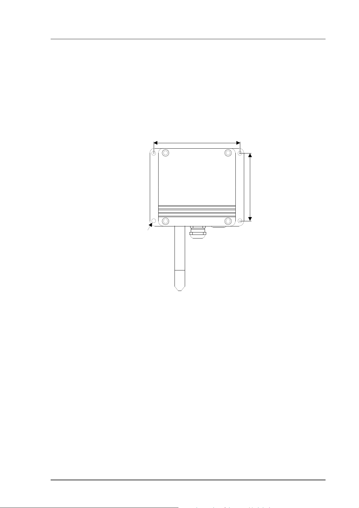
3.2.1. Mounting the HMP231
The best position for mounting the HMP231 is with the probe head pointing
downwards. Due to internal heat transfer, the transmitter should not be
mounted with the probe pointing upwards.
133
104
Ø 6.5
Figure 2 Mounting holes in the HMP230 transmitter housing.
3.2.2. Installing the HMP233, HMP234 and HMP235
It is recommended that the cable models HMP233, HMP234 and HMP235 be
mounted with the sensor head horizontally; this way, any water condensing on
the tube cannot flow onto the sensors. When there is no alternative but to
install the sensor head in the process vertically, the point of entry must be
carefully insulated. The cable must also be allowed to hang loosely as in
Figure 6; this prevents any condensed water from running onto the sensor head
along the cable.
If the process temperature is much higher than that of the environment, the
whole sensor head and preferably a piece of the cable must be inside the process.
When mounted on the side of a duct or channel, the sensor head must be inserted from the side (see Figure 8). If this is not possible and the sensor head
must be inserted from the top, the point of entry must be carefully insulated.
5
Page 12
HMP230 SERIES
User's Guide M210225en-B
NOTE
During installation the sensor head must not be unsoldered from and again resoldered to the main printed
board of the transmitter. This procedure may damage
the humidity calibration of the transmitter.
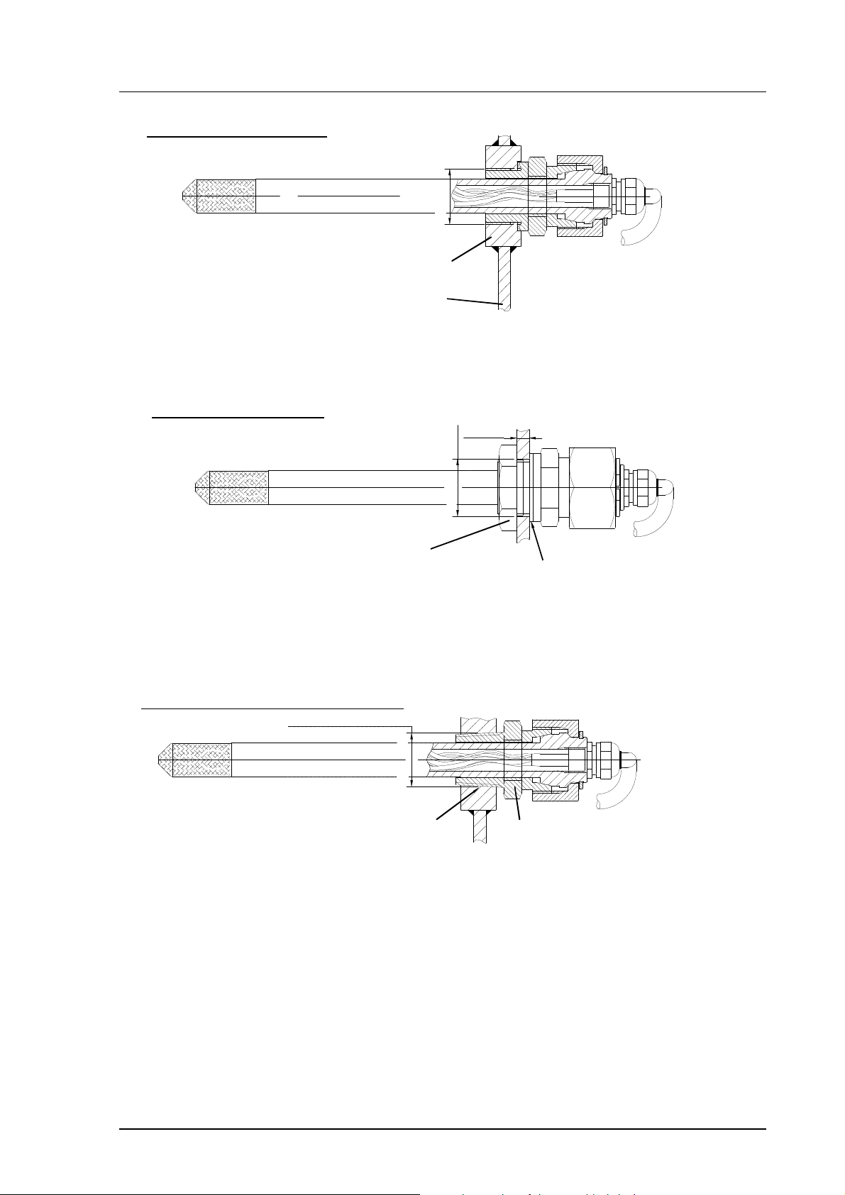
3.2.3. HMP233 transmitter
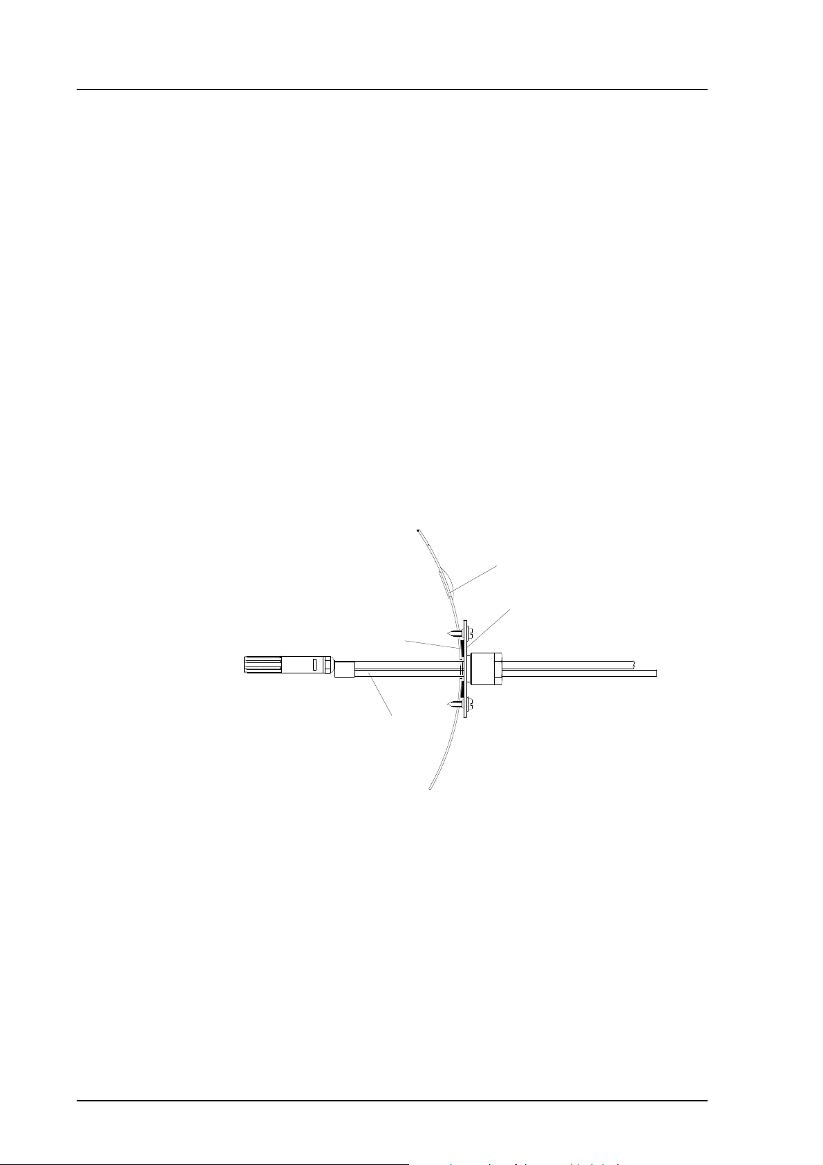
The HMP233 can be installed in ducts and channels with the help of the installation kit available; the kit consists of a flange, a supporting bar for the
sensor head cable and screws for attaching the flange to the wall of a duct.
With the help of the installation kit the distance between the sensor head and
the channel wall can be easily adjusted. The range of adjustment is 100...320
mm; the distance is measured from the tip of the sensor head to the flange.
duct wall
a plugged hole for reference
measurements
flange
sealing
supporting bar
Figure 3 Installing the sensor head of the HMP233 in a channel with
the help of flange and supporting bar.
6
Page 13
HMP230 SERIES
M210225en-B User's Guide
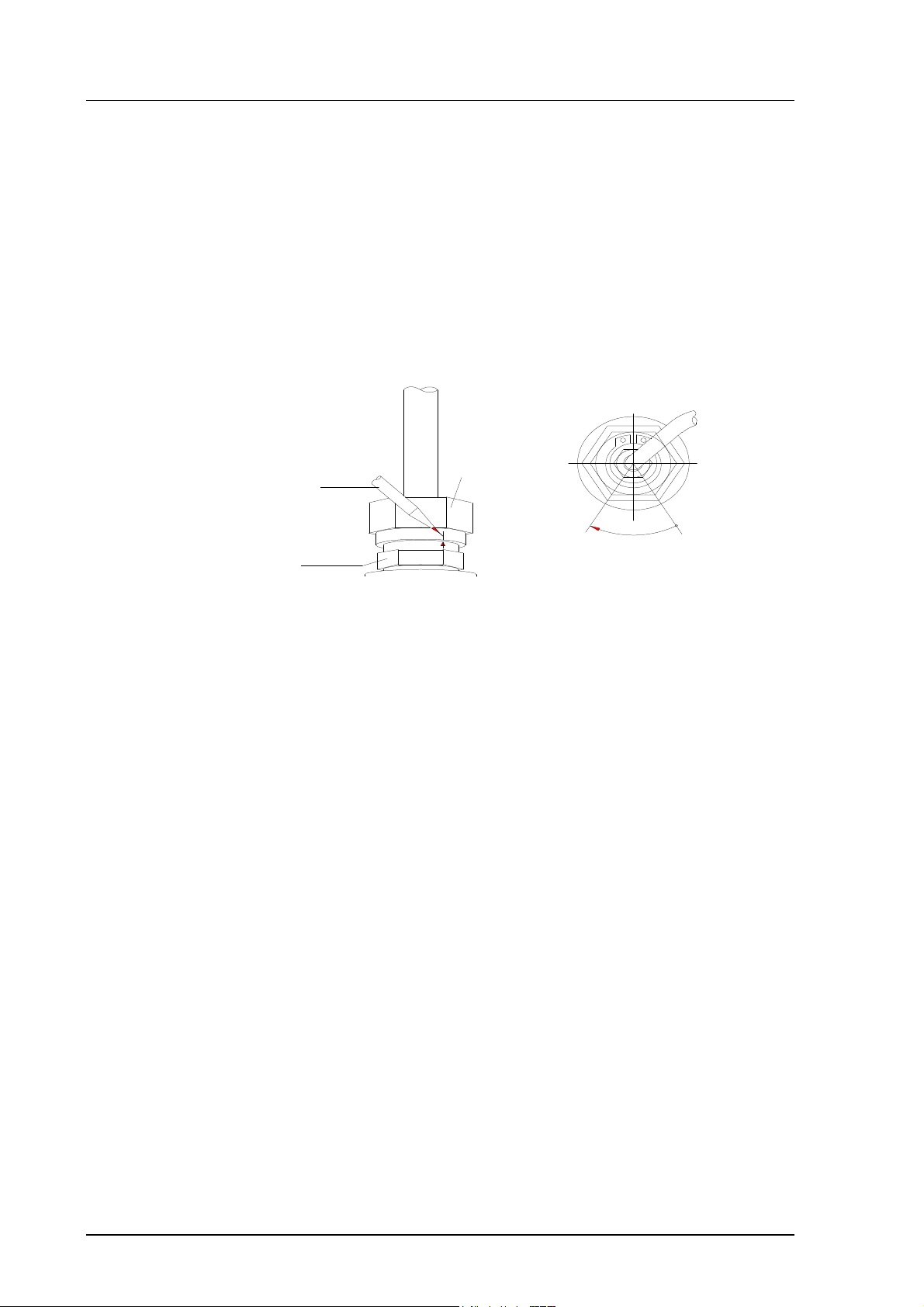
The sensor head can also be installed vertically.
When a bushing is used, its
size is selected according to
the diameter of the sensor
head; the diameter of the
cable is increased by using
e.g. tape at the bushing
Figure 4 Vertical installation of the HMP233 sensor head
3.2.4. HMP234 transmitter
The atmospheric pressure has an effect on mixing ratio, wet bulb temperature
and enthalpy. Therefore, accurate calculations can be achieved only when the
ambient pressure is taken into consideration. The pressure is used for pressure
compensation of the HUMICAP sensor in order to ensure the best possible
measurement accuracy. If the process pressure differs from normal
ambient pressure, the value has to be entered in the transmitter memory
when using the transmitters HMP234 or HMP238. The pressure to be
entered is the absolute pressure in hPa or mbar (for pressure unit conversion,
see Appendix 10).
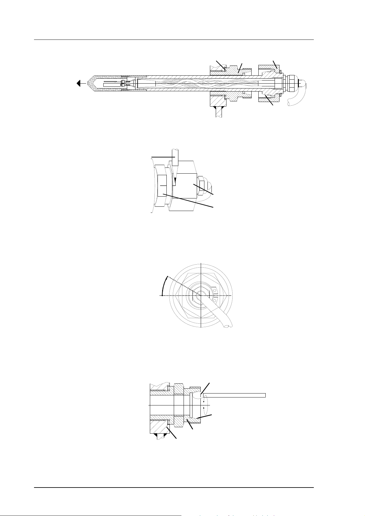
The HMP234 is supplied with a nut, a fitting body and a sealing washer. During handling the fitting body and the nut should remain in place on the body of
the sensor head to prevent damage to the highly polished surface.
To achieve a leak-tight assembly:
1. Remove the fitting body from the nut and the sensor head.
2. Fasten the fitting body to the chamber wall. Tighten the fitting body
into the threaded sleeve with a torque spanner. The tightening torque
is 150 ±10 Nm.
3. Insert the body of the sensor head into the fitting body and screw the
nut manually to the fitting body until the connection feels tight.
7
Page 14
HMP230 SERIES
User's Guide M210225en-B
sealing washer
4. Mark both the fitting body and the nut hex.
A pen
nut
fitting body
fitting body
tightening cone
nut
5. Tighten the nut a further 30° (1/12 turn) or if you have a torque spanner tighten it with a torque of 80 ±10 Nm. NOTE: after detachment
the nut must be tightened without increased effort.
30°
6. The tightening cone of the fitting body has to be cleaned and greased
after every tenth detachment. Use high-vacuum grease (Down
Corning, Europe) or a similar grease.
clean cotton stick
tightening cone
fitting body
sealing
washer
The sealing washer has to be changed every time the fitting body is
detached.
8
Page 15
HMP230 SERIES
M210225en-B User's Guide
Fasten by threaded sleeve
Sealing by Metal sealing washer DIN 7603
M22x1.5
threaded sleeve M22x1.5/Ø40 x15
sheet metal
Fasten by Nut DIN 80705
Check the thickness of the sheet metal
according to the pressure of the chamber
s=3...6mm
(boring)
nut DIN 80705-M22x1.5 (AISI 316)
tightening torque=150 Nm ±10 Nm
NPT Conical pipe threaded connection
ANSI/ASME B1.20.1-1983
sealing by anaerobic pipe thread seal
(SWAK, Cajon Company) or PTFE
(teflon) tape
Ø22+0.3
sealing by Metal sealing washer
DIN 7603
1/2 -14 NPT
fitting body. VAISALA code 17225
(AISI 316Ti). Body hex = 27 mm
tightening torque=150 Nm ±10 Nm
Figure 5 Some examples on the installation of the HMP234 sensor head
9
Page 16
HMP230 SERIES
User's Guide M210225en-B
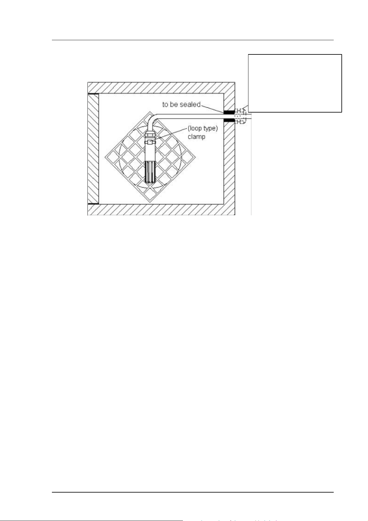
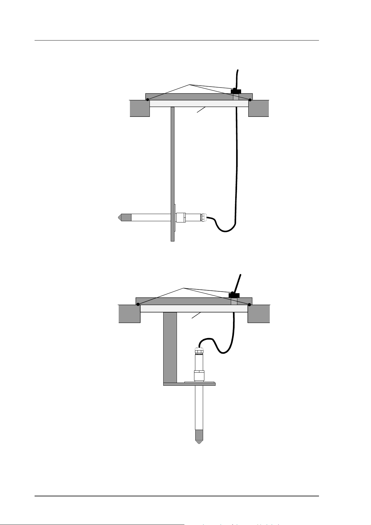
3.2.5. HMP235 transmitter
to be sealed
to be insulated
Figure 6 Installing a transmitter in a process with the sensor head
horizontally
to be sealed
to be insulated
10
Figure 7 Installing a transmitter in a process with the sensor head
downwards (not recommended)
Page 17
HMP230 SERIES
M210225en-B User's Guide
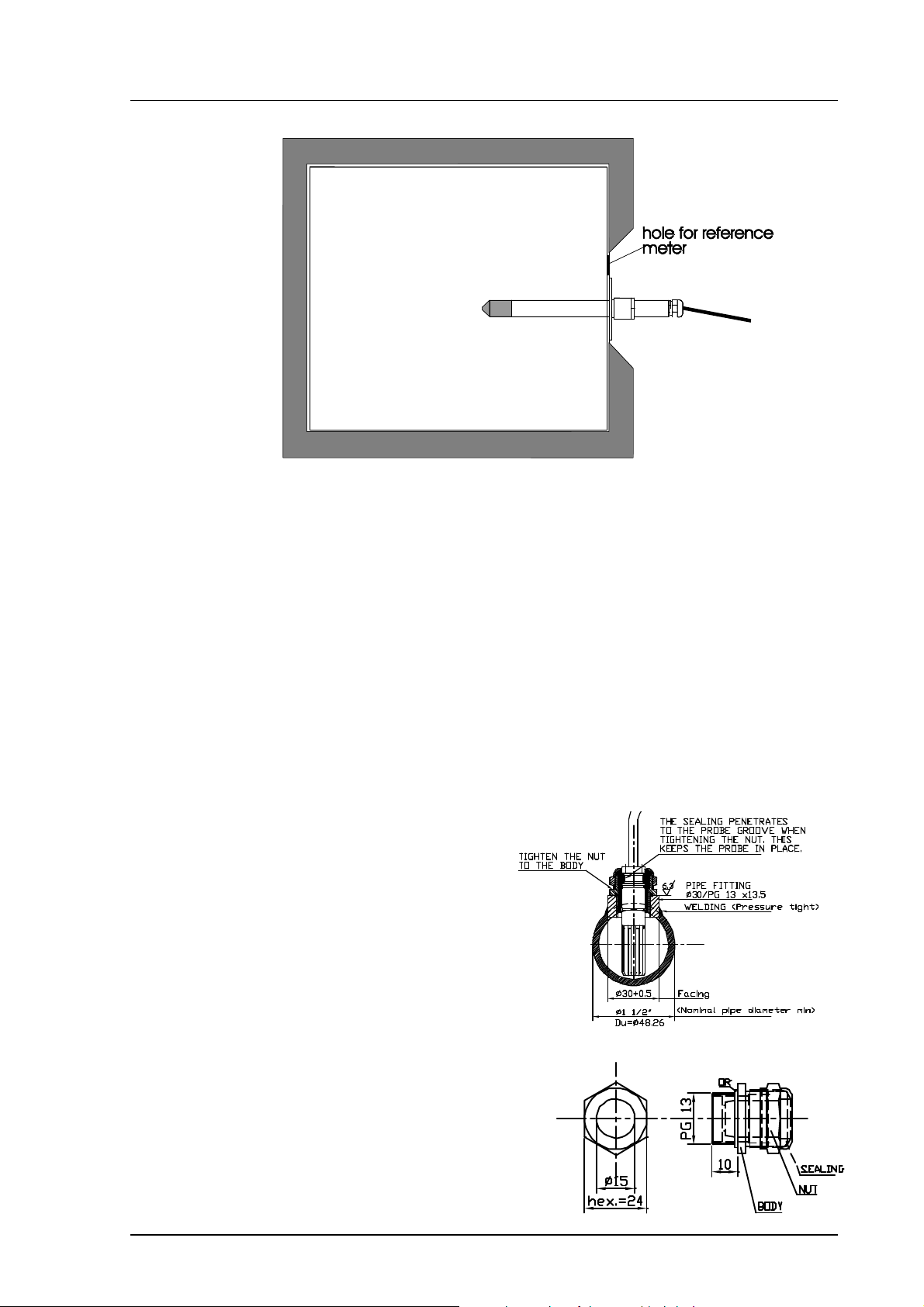
Figure 8 Mounting the sensor head on a duct or channel.
When the sensor head is installed in a duct or channel, the temperature difference between the air in the duct and outside it must be small as the sensor
head conducts heat.
3.2.6. HMP237 transmitter
HMP237 has a small size probe made of stainless steel. The sensor head
withstands temperatures -40...180 ºC (-40...356 ºF) and pressure up to 10 bar
(1MPa, 145 psi). The probe is suitable for applications where a mechanically
very durable leak proof probe is needed. The sensor head of the HMP237 can
be installed in a channel with the help of flange and supporting bar (see Figure
3). Duct and cable installations are shown in Figures 9 and 10.
Figure 9. HMP237 Duct
installation.
1. Make hole with PG13 thread
in the measurement chamber or
process wall. The smoothness of
the thread circle should be
R= 6.3 microm.
2. Install the cable gland (AGRO
nr 1113.60.15) on the thread of
the process wall.
3. Push the probe through the
gland so deep that the backside of
the probe is flust with the cable
gland nut.
4. Tighten the cable gland nut,
the probe will lift up slightly.
Cable gland (AGRO 1113.60.15)
11
Page 18

HMP230 SERIES
User's Guide M210225en-B
1. Make a hole as described in duct installation,
Temperature < 180ºC
Pressure < 10 bar
Figure 10. HMP237 cable installation.
Figure 9.
2. Take out the rubber sealing from the AGRO
Nr 1013.30.91. Drill a 6 mm hole in the middle
of the rubber sealing. Cut the jacket of the
sealing.
3. Thread the probe through the AGRO-fitting
body and nut (without the cut rubber).
4. Set the cut rubber sealing through the cable
between the fitting body and the nut.
5. Turn the fitting body to the hole, push the
rubber sealing into the fitting body and tighten
the nut.
3.2.7. HMP238 transmitter
The atmospheric pressure has an effect on mixing ratio, wet bulb temperature
and enthalpy. Therefore, accurate calculations can be achieved only when the
ambient pressure is taken into consideration. The pressure is used for pressure
compensation of the HUMICAP sensor in order to ensure the best possible
measurement accuracy. If the process pressure differs from normal
ambient pressure, the value has to be entered in the transmitter memory
when using the transmitters HMP234 or HMP238. The pressure to be
entered is the absolute pressure in hPa or mbar (for pressure unit conversion,
see Appendix 10).
It is recommended that the sensor head is installed directly in the process
through the ball valve assembly. When the ball valve set is used, the chamber
or the duct does not have to be emptied or shut down for installation or
removal of the probe. Install the sensor head transversely against the direction
of the process flow.
However, if direct installation is not possible for some reason, the probe can
be installed in a "leak-through" position provided that there is a slight
overpressure in the process. In this installation, the probe is mounted behind
the ball valve assembly. The flow passes through the sensor head and leaks
out through a vent hole in the fitting body. However, make sure that the
temperature at the measurement point is equal to that of the process.
12
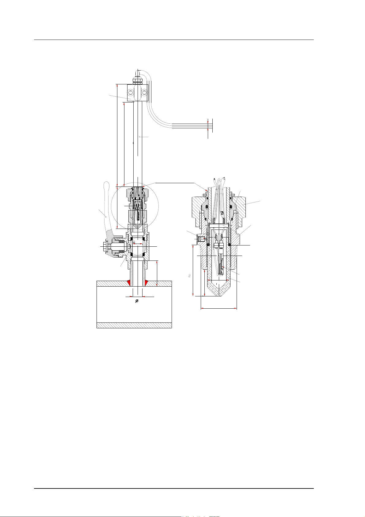
Page 19
HMP230 SERIES
PROBE UP
PROBE
PUSHED
DOWN
cable length
2, 5 or 10 m
ø5.5
178
31
ø13.5
adjustment
range120 mm
29
R1/2 ISO 7/1
non leaking screw (A)
(factory setting)
or leak screw (B)
(included in the package)
149
clasp nut
fitting body
M210225en-B User's Guide
Figure 11 HMP238 Probe dimensions (in mm)
NOTE
Take care not to damage the pipe of the probe. If the
pipe is damaged, the probe head is less tight and it will
not go through the clasp nut.
3.2.7.1. Mounting; overview
fitting body
hex = 24mm
tapered thread
R1/2 ISO 7/1
Examples of
sealings:
sealing with:
1. LOCTITE® No 542 + activ. No 7649 (t=-55...+150 °C)
2. MEGA-PIPE EXTRA No 7188 (t=-55.. .+170 °C)
3. PTFE tape (t=-60...+210 °C) NOTE: the tape does not lock
the parts together. Therefore, use two fork spanners (hex 24 and
27 mm) for tightening and opening the clasp nut of the probe
(provided with
the probe)
Thread for the
fitting body:
>10.5mm
Process or pipe wall
parallel thread
G1/2 ISO 228/1
(BS 2779, JIS B0202)
ø19mm dr illing
>40mm
Figure 12 Sealing and thread cutting for the fitting body
13
Page 20
HMP230 SERIES
User's Guide M210225en-B
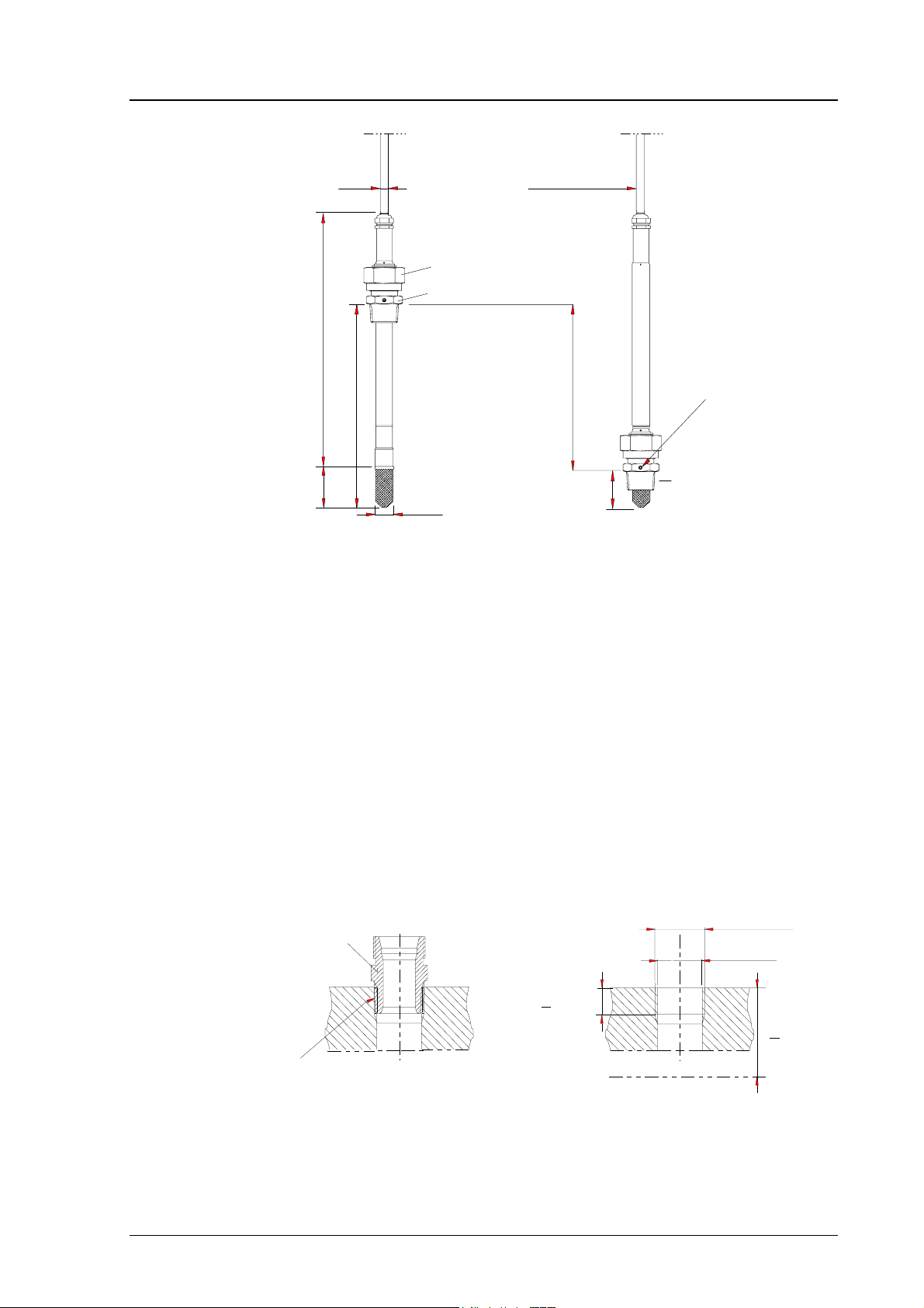
The fitting body can be installed e.g. on standard pipe fittings (G 1/2 ISO
228/1) or on a thread in the process wall. If the wall thickness is more than
10.5 mm, it is recommended to use a welded sleeve (see Figure 14). Note that
the minimum recommended distance of the fitting body and probe head is 40
mm (see Figure 12).
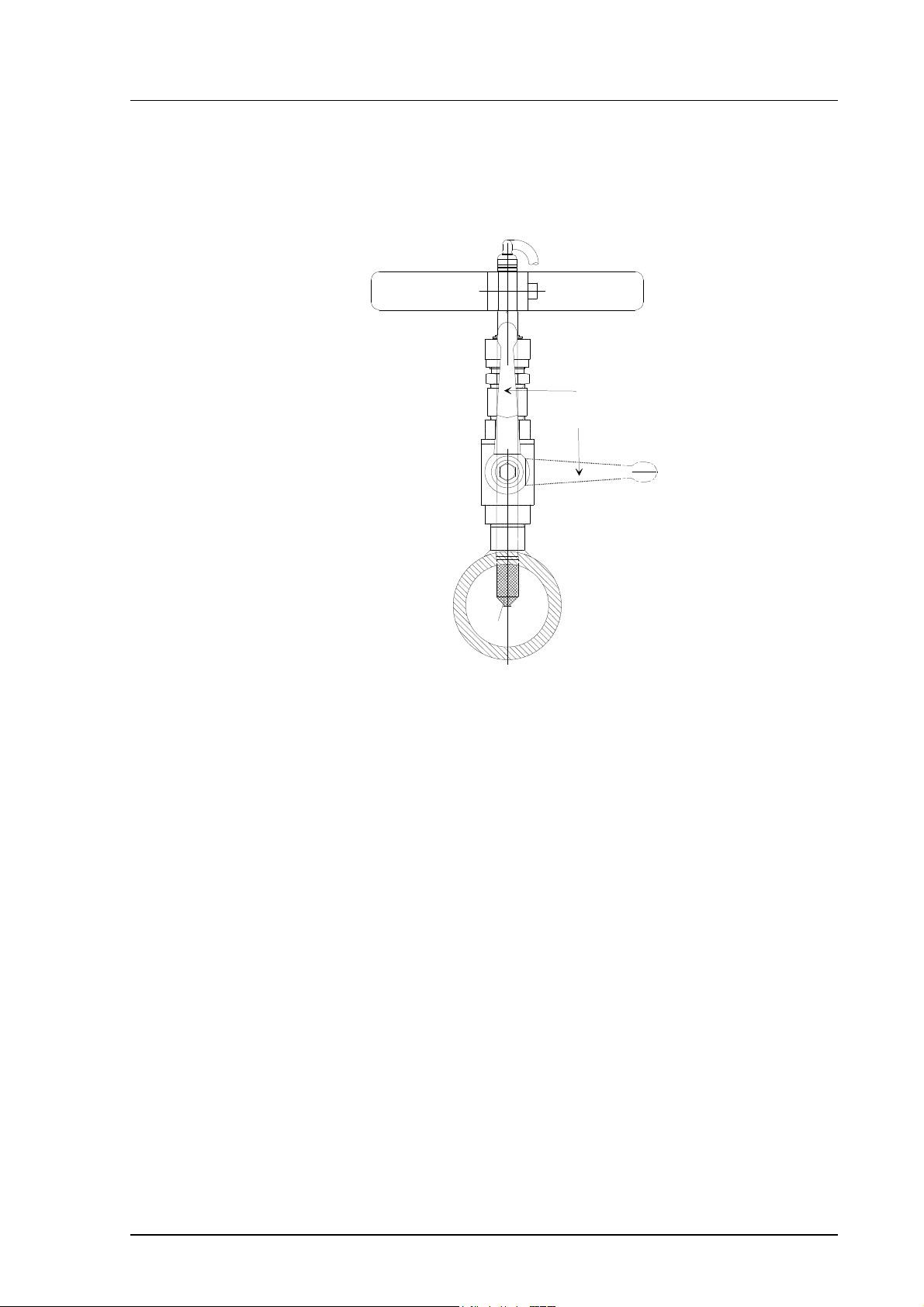
Adjust the probe to a suitable distance according to the type of installation and
tighten the clasp nut first manually; mark the fitting body and the clasp nut
and tighten the nut a further 50...60° with a fork spanner (see Figure 13).
probe
a pen
clasp nut
60°
fitting body
max.
Figure 13 Tightening the clasp nut.
NOTE
Be careful not to tighten the clasp nut more than 60° as
this may result in difficulties when trying to open it.
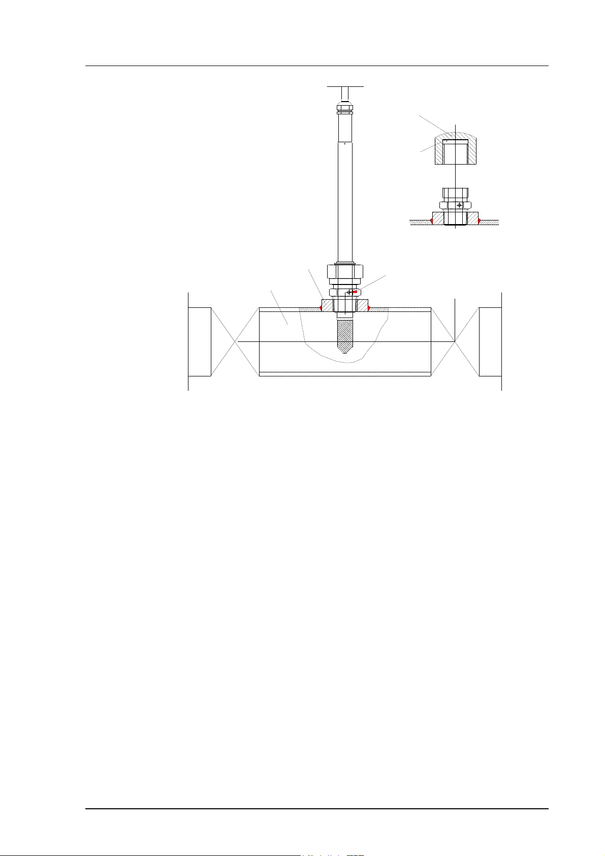
When the probe is installed directly on the process wall or pipe, note that a
closing valve may be needed on both sides of the installed probe so that the
sensor head can be removed from the process for calibration and maintenance.
If the sensor head is installed in a pressurized chamber, always make sure that
the pressure of the chamber is equalized with the ambient pressure prior to
removing the probe.
14
Page 21
HMP230 SERIES
M210225en-B User's Guide
capped nut
DIN 917-M22x1.5
when the probe is pulled
out for maintenance, cap
the hole with a capped nut;
this way, the process can be
open although the probe is
not in place
sealing
welded sleeve
(G1/2)
process pipe
Non leaking screw
(screw A)
closing valve
(ball valve)
Figure 14 Installing the sensor head directly on the process wall
15
Page 22
HMP230 SERIES
User's Guide M210225en-B
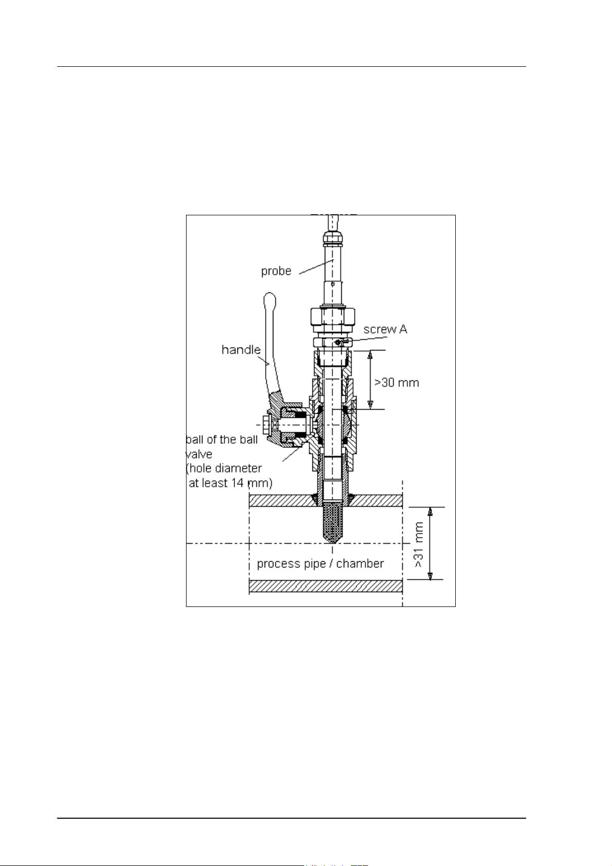
3.2.7.2. Installing the probe through the ball valve assembly
The best way to install the sensor head is through the ball valve assembly. Use
a 1/2” ball valve assembly with a ball hole of ∅14 mm or more. In this kind of
installation, it is not necessary to empty or shut down the process for installing
or removing the sensor head. If the sensor head is installed in a process pipe,
please note that the nominal size of the pipe must be at least 1 inch. See pages
16 - 19 for detailed instructions.
16
Figure 15 Installing the sensor head through the DMP248BVS ball valve
assembly
NOTE
The probe can be installed in the process through the
ball valve assembly provided that the process pressure
is less than 10 bars. This way, the process does not have
to be shut down when installing or removing the probe.
However, if the process is shut down before removing
the probe, the process pressure can be max. 40 bars.
Page 23
HMP230 SERIES
d
M210225en-B User's Guide
See Figure 16 through Figure 18 for detailed description of installation
through the ball valve assembly. This installation is possible provided that
the process pressure is less than 10 bars. Note also that if the sensor head is
installed in a process pipe, the nominal size of the pipe must be at least 1 inch.
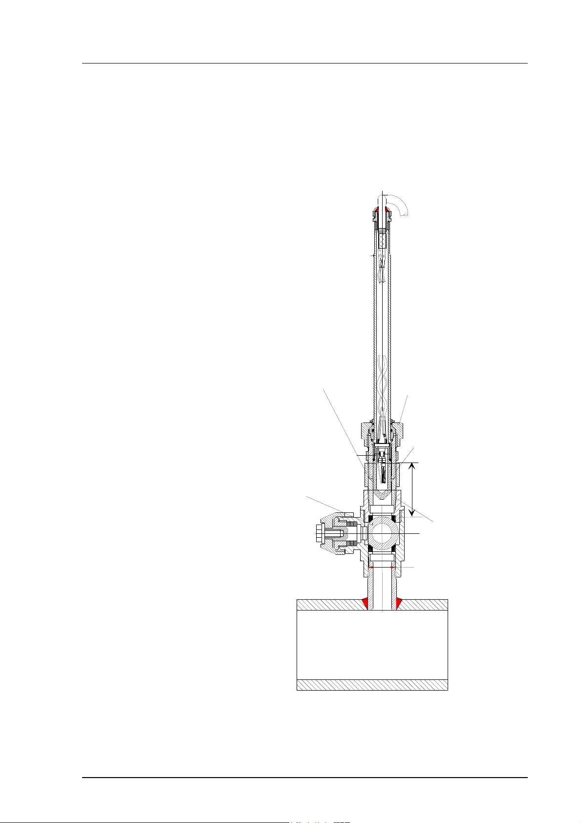
• STEP I: mount the probe with the ball valve assembly closed; tighten the
clasp nut manually
bushing R1/2 cone/G1/2(40 bar)
e.g. Camozzi 2520-1/2-1/2
(the bushing serves for
moving the probe (sinter)
to such a distance from the
ball valve that the valve
can be closed)
ball valve 1/2" (40 bar)
e.g. Atlas Copco:BAL-1A 15 (G1/2)
clasp nut
fittin g body
R1/2 cone, seale
>30 mm
bushing
R1/2 cone
sealed
nipple
R1/2 cone
sealed
Figure 16 Installing the probe through the ball valve assembly; step 1.
17
Page 24
HMP230 SERIES
User's Guide M210225en-B
• STEP 2: open the ball valve assembly
manual
press
tool
120mm
probe pipe
148 mm
adjustment range
marking groove
handle
61
ø5.5
fitting
ferrule
c lasp nut
(hex 27 mm)
fitting body
(hex. 24 mm)
O-ring
DRYCAP® sensor
filter
ball of the
ball valve
ø14
> 14
=
leak screw (B)
(hex. 1.5 mm)
(40)
29
15
R1/2 ISO 7/1
ø13.5
Figure 17 Installing the probe through the ball valve assembly; step 2
(measures in mm)
18
Page 25
HMP230 SERIES
M210225en-B User's Guide
• STEP 3: push the probe head through the ball valve assembly into the
process. If the pressure is high, use a manual press tool. Note that the
sensor head must be pushed so deep that the filter is completely inside the
process flow.
MANUAL
PRESS TOOL
VALVE OPEN
VALVE CLOSED
FILTER
Figure 18 Installing the probe through the ball valve
assembly: step 3
For by-pass measurements, the probe is mounted behind the ball valve
assembly and non-leaking screw A on the fitting body is replaced with leaking
screw B and O-ring is placed on the groove of the sintered filter. Screw B has
a small (0.08 mm) laser-made hole in the middle; the gas or air to be measured
passes through the sintered filter and by the sensor, and leaks out through the
screw. The process pressure reduces in the hole of the screw B. This
installation is recommended if the process flow rate is >20 m/s and there is an
over-pressure in the process.
19
Page 26
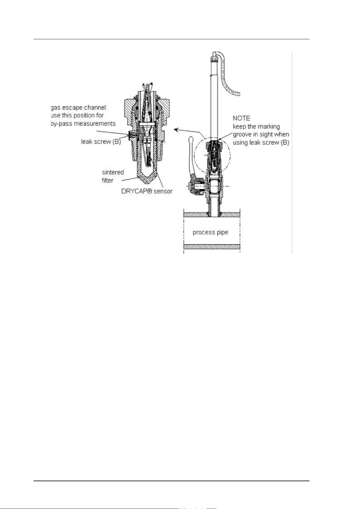
HMP230 SERIES
User's Guide M210225en-B
Figure 19 Installing the sensor head for by-pass measurements.
When pushing the probe head through the ball valve assembly, be careful not
to break the sintered filter. Open and close the ball valve assembly with the
marking groove always in sight. In by-pass measurements, the clasp nut is
tightened manually prior to pressing the probe through the valve. When the
probe has been pressed through and the valve is open, the nut is tightened
50...60° with a fork spanner (hexagon 27 mm).
3.3. Grounding
A single electrical cable with a screen and three to ten wires is recommended
for power and analogue output/serial bus connections. The cable diameter
should be 7...10 mm.
The screen of the electrical cable must be grounded properly to achieve best
possible EMC performance. Recommended cable shield is done in the cable
gland as shown below.
• remove the brass disks, rubber ring and nut from the transmitter
housing
20
• strip 165 mm of the cable insulation, but leave 25 mm of the braid
visible
• slip the nut and rubber ring over the cable insulation
Page 27
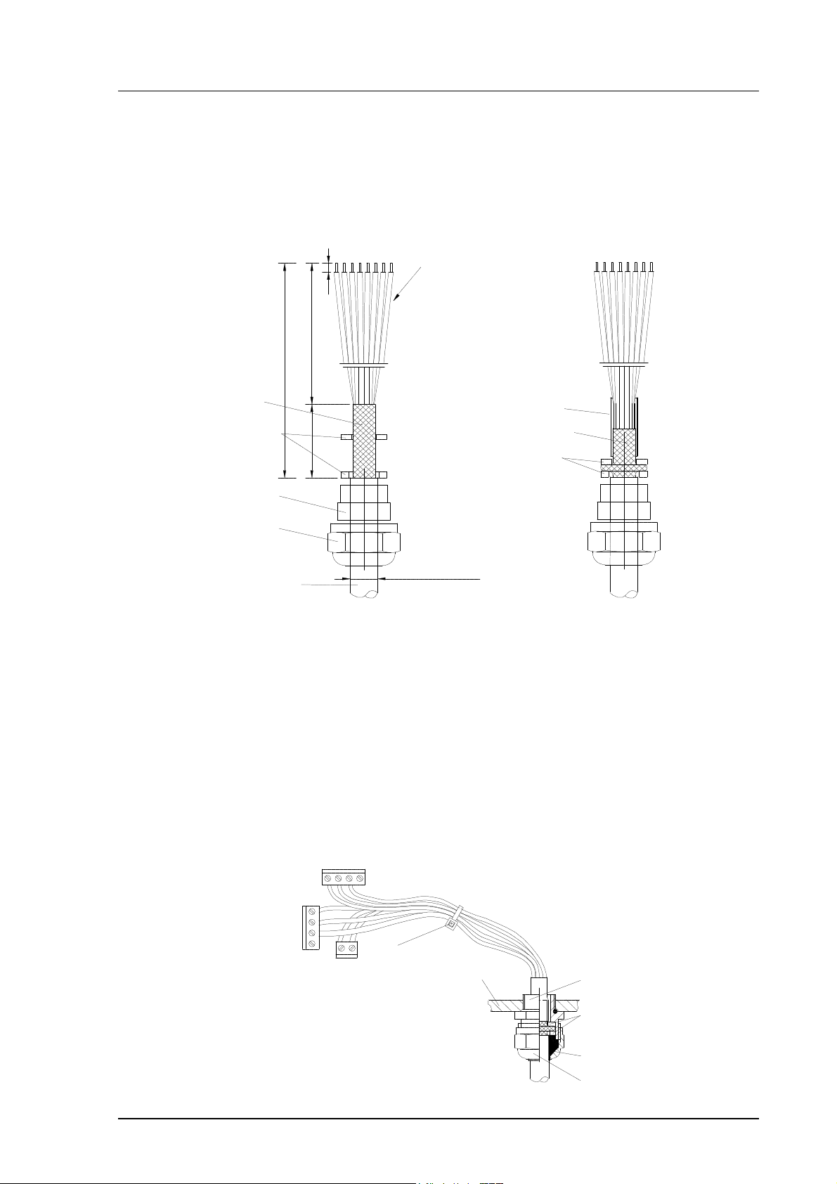
HMP230 SERIES
brass disks
rubber ring
M210225en-B User's Guide
• slip the brass disk that has the bigger hole in it over the braid so that
it rests against the cable insulation
• slip the other brass disk over the wires to the middle of the braid
flexible wires 0.5 mm²
(AWG 20), stranded wires
recommended
3
140
165
braid
brass
disks
rubber
ring
nut
cable
• push back the braid and press it between the two brass disks to
25
D = Ø 7...10 mm
(If the cable diameter is less
than 7mm, use a shrinking
tube or an adhesive tape)
shielding tube
braid
brass disks
achieve a full 360° grounding; the fold between the disks should have
the same diameter as the brass disks
• secure the braid with a shielding tube
• insert the wires into the transmitter housing through the gland.
• tighten the nut
• connect the wires into the screw terminals and fasten a cable tie
around the wires
cable tie
transmitter housing
gland
nut
21
Page 28
HMP230 SERIES
+
POWER SUPPLY
User's Guide M210225en-B
NOTE
When the cable is grounded as above, the metallic parts
of the sensor head, the shield of its cable, the transmitter housing and the shield of the signal cable to external
system are all connected to each other. After this the
whole system can be grounded from one point only. If
the grounding is made via several points (sensor head,
transmitter housing, signal cable), make sure that the
different groundings are made to the same grounding
potential. Otherwise harmful grounding currents may be
generated. If you do the grounding via the transmitter
housing, use one serrated lock washer between a mounting screw and the housing; the lock washer breaks the
paint on the housing.
When mains power supply is in use, the housing must be grounded by protective ground wire using a grounding screw at the right-hand side of the power
supply module (see Appendix 2).
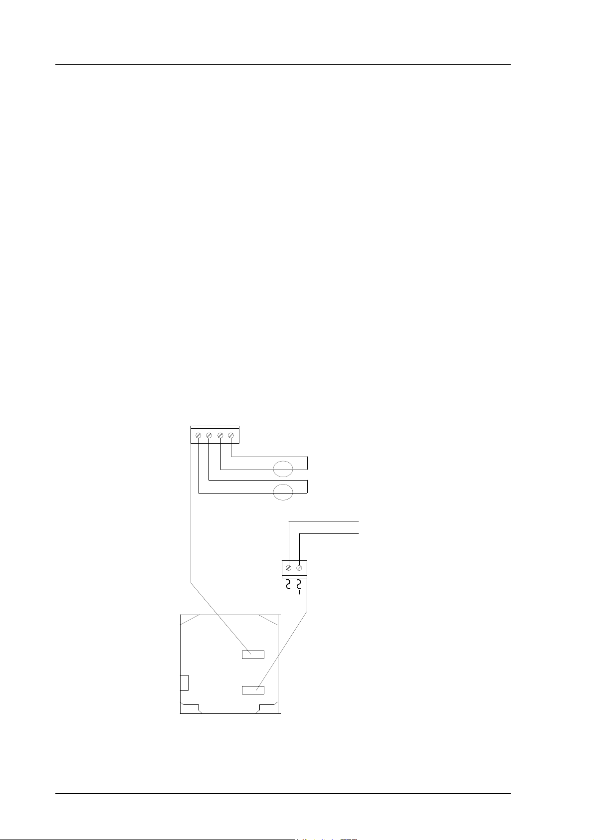
3.4. Electrical connections
CH2
CH1+
CH1-
X2
CH1- and CH2- are connected
CH2-
together internally
+
V
mA
+
V
mA
CURRENT/VOLTAGE
-
OUTPUTS
-
(INTERNAL OR
EXTERNAL)
Do not use power supply
ground (-) as output signal
ground
24 V +
22
X1
OPENED COVER OF THE HMP230
Figure 20 Electrical connections
Page 29
HMP230 SERIES
M210225en-B User's Guide
Power supply 24 VDC
24 VAC (see page 23)
with power supply module 115/230 VAC
Output signals 0...20 mA, 4...20 mA
0...1 V, 0...5 V, 0...10 V
Power supply ground (-) is connected to the housing with parallel connection
of 15 nF capacitor and 300 kΩ resistor.
See Appendix 2 on how to connect the power supply module to the
transmitter.
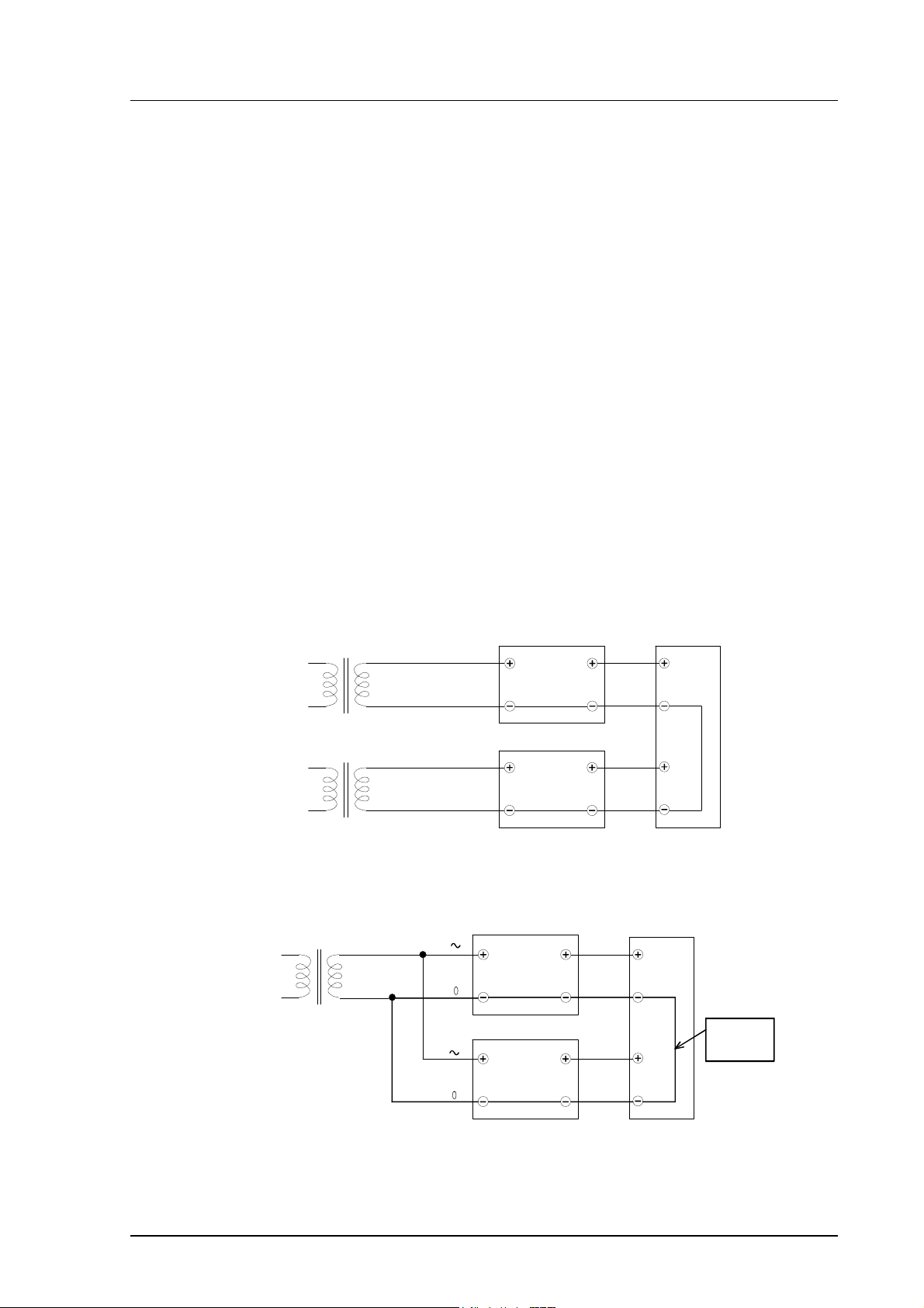
3.4.1. Connection to a 24 VAC supply
The HMP230 transmitters can also be connected to a 24 VAC supply without
an external rectifier. However, when more than one transmitter is connected to
one 24 VAC transformer, a common loop is formed and there is an increased
risk of a short-circuit. To avoid this, always use separate floating supply for
each transmitter (see Figure 21 A). However, if several transmitters have to
share one transformer, the phase (∼) must always be connected to + connector
in each transmitter (see Figure 21 B).
A) NO COMMON LOOP FORMED - RECOMMENDED
HMP230 transmitter
24 VAC
24 VAC
HMP230 transmitter
B) COMMON LOOP FORMED -
HMP230 transmitter
24 VAC
supply
voltage
signal
supply
supply
voltage
output
voltage
signal
output
NOT RECOMMENDED!
signal
output
Controller
Controller
shared
common
line
supply
voltage
signal
output
HMP230 transmitter
Figure 21 Connecting the transmitters to a 24 VAC supply
23
Page 30

HMP230 SERIES
User's Guide M210225en-B
4. COMMISSIONING
When HMP230 transmitters leave the factory, their measurement ranges and
output signals have already been scaled according to the order form completed
by the customer. Units are calibrated at the factory and ready to operate when
the power is turned on. If you take into use active current, voltage or serial bus
outputs, make these connections first; Appendix 9 describes them in detail.
NOTE
Make sure that the power is not turned on until cables
have been connected to screw terminals!
In transmitters with display, the software version appears for a few seconds
when the power is turned on. After this, measurement results appear
automatically. Should an error message appear on the display, consult
Appendix 5.
If your transmitter has a blank cover and the LED indicator inside the housing
lights up, consult Appendix 5 for further information.
Appendix 7 contains information on how to determine the ranges for alarm
outputs and alarm controls when an alarm output unit is used.
4.1. Changing the parameters
If necessary, the user can subsequently change the measurement units between
metric and non-metric and select and scale the output signals with software
functions. This is done through commands, either utilizing the menus on the
local display or giving commands through the serial interface (see
Appendices). Most often the commands are used to change the settings of the
two analogue channels.
4.2. Security lock jumper
Before the settings can be changed, the user must first remove the security
lock jumper in connector X15 (see Figure 22). The security lock jumper makes
it impossible to change the transmitter settings by mistake.
24
Page 31

HMP230 SERIES
M210225en-B User's Guide
X15
CHANGE OF SETTINGS
DISABLED
OPENED COVER OF THE HMP 230
Figure 22 Location of the security lock jumper
When the security lock jumper is connected, some commands cannot be used,
see Chapter 5.
If you wish to take into use variables that are not included in the configuration
of your transmitter, contact Vaisala or a Vaisala representative.
4.3. Selecting the analogue outputs
The HMP230 transmitters can be ordered with the required current or voltage
outputs already selected. If the outputs need to be changed, move the jumpers
in connector X15 into positions as shown in Figure 23.
25
Page 32

HMP230 SERIES
OPENED COVER OF THE HMP230
User's Guide M210225en-B
CH1
CH1
CH1
CH1
CH2
CURRENT OUTPUTS
0 ... 20 / 4 ... 20 mA
CH2
VOLTAGE OUTPUTS
0 ... 5 V / 0 ... 10 V
CH2
VOLTAGE OUTPUTS
0 ... 1 V
CH2
CH1 0 ... 1 VOLTAGE OUTPUT
CH2 CURRENT OUTPUT
CH2
CH1
CH1
CH2
CH1
CH2
CH1
CH2
X15
Figure 23 Selecting the analogue outputs with jumpers.
The software also has to be informed which outputs are in use. This is
done either through the serial interface or the menus on local display when one
is in use. The serial command is AMODE and the display/keypad command
"Mode ð Analog outputs ð Mode" (see Chapter 5). If the outputs need to
be scaled, see serial command ASCL and the display command "Mode ð
Analog outputs ð Scale".
All jumpers are used only with the 0...1 V outputs. When other outputs are in
use, the spare jumpers are kept in connector X55.
26
Page 33

HMP230 SERIES
OPENED COVER OF THE HMP230
OPENED COVER OF THE HMP230
M210225en-B User's Guide
X55
spare jumpers
Figure 24 Spare jumpers
4.4. Connecting the RS 232C serial bus
RX
GND
TX
NC
X6
Figure 25 Serial bus connections
To connect a PC to the HMP230 transmitters via the RS 232C serial bus, one
of the following cables is required. The type of cable depends on the terminal
and the connector type.
27
Page 34

HMP230 SERIES
HMP 230
User's Guide M210225en-B
RXD
RXD
RXD
TXD
TXD
TXD
TX
GND
RX
TX
GND
RX
TX
GND
RX
PC
TERMINAL
D9S
D25S
D25P
2
5
3
4
6
7
8
3
7
2
5
6
8
20
3
7
2
Figure 26 Connection of cables
When the serial bus has been connected between the PC and the transmitter,
the PC is switched on. When using a PC, a terminal emulation program (e.g.
Procomm Plus, Datastorm or Windows terminal) is started.
The factory settings for data transfer are:
• 4800 baud
• even parity
• 7 data bits
• 1 stop bit
• full duplex
NOTE
When the serial bus settings are changed, the transmitter has to be reset before the new settings become effective.
The processor does not allow the following combinations:
• no parity, 7 data bits, 1 stop bit: if this combination is given the
HMP230 program will change the number of stop bits to 2
• even or odd parity, 8 data bits, 2 stop bits: if this combination is given
the program changes the number of stop bits to 1
Refer to the manuals of the PC and the terminal emulation program when
giving serial settings.
The RS 232C screw terminal cannot be used if an RS 485/422 serial module
or a current loop module is used. See Appendices 3 and 4 on how to install
and operate these modules.
28
Page 35

HMP230 SERIES
OPENED COVER OF THE HMP230
M210225en-B User's Guide
In calibrating or changing the settings of the transmitter it can be more convenient to use the connector X17, if connector X6 is already in use. This connector, however, transfers only RS 232C signals. If an RS 485/422 serial port
module or a current loop module has been installed, it has to be removed before communicating through the X17 connector.
RX GND TX
X17
Figure 27 Location and connections of connector X17
NOTE
Some PC computers can generate interferences to the
measured humidity and temperature values if the
transmitter and the PC are connected to different mains
outlets. To minimize the possibility of these interferences, always use the same mains outlet (same phase of
the mains electricity) for the PC and the power supply
of HMP230. This is especially the case when using the
serial line connector X17. The serial line connector X6
is more immune to these interferences than connector
X17.
4.4.1. Reverting to factory settings of the serial port
If the serial port settings are not known, no commands can be given via the
serial interface. The settings can be reverted to the factory settings by inserting
a jumper in connector X16. The jumper must be inserted when the power is
on!
X16
Figure 28 Forcing the serial port settings back to factory settings
29
Page 36

HMP230 SERIES
User's Guide M210225en-B
When the jumper is inserted the serial line factory settings become valid, but
only temporarily. The transmitter must be given new settings; otherwise
the transmitter uses the old, unknown settings after power-up. When the
new settings have been given, the transmitter must be reset. The jumper must
be removed before the transmitter is reset; if the jumper is in place when
power is turned on, the transmitter does not work.
After jumper insertion the transmitter is in STOP mode, ready to receive
commands.
The same method is used when the transmitter is in POLL mode and the user
has forgotten its address.
CAUTION
Inserting a jumper in any other place in connector X16
voids the guarantee of the transmitter.
30
Page 37

HMP230 SERIES
M210225en-B User's Guide
5. CONNECTION TO PC
Connect a serial connection cable to the appropriate connectors on your PC
and in the HMP230 (see Appendix 11, connector X6).
5.1. Giving the communication parameters
Give the communication parameters when using this terminal session for the
first time; save them for future use. See instructions in the following tables.
Giving parameters in Windows 3.1
MENU DESCRIPTION
PROGRAM MANAGER
ò
ACCESSORIES
ò
TERMINAL
ò
Settings
ò
Communications
ò
File
ò
Save as
double click
double click
click
click and select parameters
(see figure on next page);
click OK
move the cursor to:
click
click and save settings: type
the name of the file and
click OK
31
Page 38

HMP230 SERIES
User's Guide M210225en-B
NOTE: select the
connector
according to
your computer.
Select the
connector first
and give then
other parameters
Giving the communication parameters in Windows 3.1
Giving parameters in Windows 95 and Windows NT
WINDOWS 95 WINDOWS NT
MENU WHAT TO DO MENU WHAT TO DO
Start Start
ò
Programs Programs
ò
Accessories Accessories
ò
HyperTerminal
ò
Hypertrm
ò ò
Connection
Description
ò
Phone Number
ò ò
COM x properties
move the cursor to:
move the cursor to:
move the cursor to:
click
move the cursor to:
double click
type the name of the
connection in the
appropriate field and
select an icon if
available; click OK.
move the cursor to the
field CONNECT USING
and select 'direct to
COM x' (x = serial port
available); click OK
select parameters
according to the
previous figure; click
OK
ò
ò
ò
HyperTerminal
ò
Hyperterminal
Connection
Description
Connect to
COM x properties
move the cursor to:
move the cursor to:
move the cursor to:
move the cursor to:
click
type the name of the
connection in the
appropriate field and
select an icon if
available; click OK.
move the cursor to the
field CONNECT USING and
select 'COM x' (x =
serial port available);
click OK
select parameters
according to the previous
figure, click OK
32
Page 39

HMP230 SERIES
M210225en-B User's Guide
Selecting the parameters in Windows 95 and NT
33
Page 40

HMP230 SERIES
User's Guide M210225en-B
6. COMMANDS
The HMP230 transmitters use microprocessors; therefore their configuration
can be set according to the user's needs. This is done through commands,
either utilizing the menus on the local display or giving commands through the
serial interface (see Appendix 1). Most often the commands are used to
change the settings of the two analogue channels.
A limited range of commands can be given by using the three press switches up, down and enter - inside the transmitter housing. Four LEDs indicate the
command given with the up and down switches. The switches and LEDs are in
all HMP230 transmitters. LED commands can be used to calibrate the transmitters (both humidity and temperature) or to calibrate the analogue outputs.
A full range of commands can be given through the display/keypad or through
the RS 232C serial bus. The commands can be used e.g. to select and scale the
outputs, to calibrate the humidity and temperature channels as well as the
analogue outputs and to set the serial interface.
6.1. Commands and security lock jumper
In order to prevent any tampering with the transmitter settings, the transmitters
cannot be calibrated, the analogue outputs set or the analogue output
quantities selected or scaled unless the security lock jumper has been disconnected. The commands involved are:
• all LED commands
• display/keypad commands:
Cali ð RH cal T cal
Analog outputs
Mode ð Analog outputs ð Mode
More ð More ð Frost
More ð Filt
• serial commands:
CRH, CT, CTA, FCRH, ACAL; AMODE, ASEL, ASCL, FROST,
FILT
Scale
34
In the following, the description of these functions is preceded with a reminder of the security lock jumper:
Disconnect the security lock jumper!
Page 41

HMP230 SERIES
OPENED COVER OF THE HMP230
M210225en-B User's Guide
6.2. LED commands
NOTE
If the transmitter has a display/keypad cover, the LED
commands cannot be used.
LED commands can be used to operate the transmitters in the field. These
commands can be used in humidity and temperature calibration and calibration
of the analogue outputs.
Open the housing and press any one of the three press switches. The LEDs
will light up for 2...3 seconds.
UP
DOWN
ENT
press switches
LEDs
Figure 29 Location of press switches and LEDs
Use the up and down switches (marked with arrows on the printed board) to
find the desired command code and acknowledge it with the ENT switch. The
command codes are (l = lit, ¡ = dark):
¡¡¡¡ (0) return to normal state
¡¡¡l (1) relative humidity calibration
¡¡l¡ (2) temperature calibration
¡¡ll (3) calibration of analogue outputs
l¡¡¡ (8) relative humidity calibration after sensor change
35
Page 42

HMP230 SERIES
User's Guide M210225en-B
6.3. Display/keypad commands
6.3.1. Display mode
In the display mode the transmitters output measurements on the display; different quantities can be scrolled with the arrow keys according to the variables
selected when ordering the transmitter. The first line is scrolled with button σ
and the second line with button τ. All selections are stored with ENTER. The
selected quantities appear on the display also after power failure. After reset
the transmitters are always in the display mode.
The display also shows error messages and alarms if they occur.
6.3.2. Command mode
Press the CL key to enter the command mode. The first display is the main
menu:
The commands can be scrolled with arrow keys. The currently active
command flashes; a command is selected with the ENT key. When a menu is
displayed, either the first command or the currently valid setting flashes. The
CL key takes the transmitter back to the display mode.
6.3.3. Entering numbers
When the transmitter needs numbers to be entered into the program (e.g. when
scaling or setting the analogue outputs, in calibration or when giving the
transmitter an address), the field is either empty or the currently valid figure is
displayed. Any previously given value is deleted with the CL key.
When the field is empty, a cursor blinks at the right side of the display.
Pressing the arrow keys brings either a blank ( ), a comma (,), a dash (-), a full
stop (.) or a number from 0 to 9 on the display. The right character is selected
with ENT; after that the number or numbers move left one step. Entering
numbers is ended with selecting a blank ( ) and pressing ENT. The last character entered can be deleted with CL. If CL or ENT key is pressed when the field
is empty, the program returns to the previous display.
With some commands (e.g. calibration) the figures are changed using the arrow keys. When an arrow key is pressed continuously for a while, the numbers
start changing at an increasing rate.
36
Page 43

HMP230 SERIES
M210225en-B User's Guide
6.3.4. Analogue output commands
6.3.4.1. Selecting the output (mA/V)
Disconnect the security lock jumper!
• Select Mode in the main menu and Analog outputs in the Mode
menu:
• Select Mode ( mA / V ). The current settings for channel 1 are dis-
played:
• If the settings are correct, press ENT.
• If the settings need to be changed, press CL:
− the quantity (mA/V) starts flashing; it can be changed with the ar-
row keys and acknowledged with the ENT key
− the lower limit starts flashing
− acknowledge the lower limit with ENT or start changing it by
pressing CL; a new lower limit is given one character at a time
with the arrow keys
− the upper limit starts flashing
• acknowledge the upper limit with ENT or start changing it by pressing
CL; a new upper limit is given one character at a time with the arrow
keys
When channel 1 has been set, the program goes on to channel 2; the procedure
is the same as with channel 1.
NOTE
Also the analogue output jumpers must be set to correct
places (see Figure 23).
37
Page 44

HMP230 SERIES
User's Guide M210225en-B
6.3.4.2. Selecting and scaling the analogue output quantities
Disconnect the security lock jumper!
• Select Mode in the main menu and Analog outputs in the Mode
menu:
• Select Scale. The quantity and scaling for channel 1 are displayed:
• If the settings are correct, press ENT.
• If the settings need to be changed, press CL:
− the quantity (RH, T, Td, x, a, Tw, h) starts flashing; it can be
changed with the arrow keys and acknowledged with the ENT key
− the lower limit starts flashing
− acknowledge the lower limit with ENT or start changing it by
pressing CL; a new lower limit is given with the arrow keys
− the upper limit starts flashing
− acknowledge the upper limit with ENT or start changing it by
pressing CL; a new upper limit is given with the arrow keys
• When channel 1 has been set, the program goes on to channel 2; the
procedure is the same as with channel 1.
Please note that the selections that are possible are affected by the choice of
output parameters. Also make sure that the temperature measuring ranges are
not exceeded, e.g. the HMP231 cannot be used in temperatures above +60 °C.
38
Page 45

HMP230 SERIES
M210225en-B User's Guide
6.3.5. Output via the serial bus
6.3.5.1. Turning the serial interface echo ON/OFF
• Select More in the main menu, select More in the More menu and
select Echo in the second More menu.
• Use the arrow keys to select the right alternative and press ENT.
6.3.5.2. Serial bus settings
• Select Seri in the main menu; the currently valid serial interface set-
tings are displayed:
• If the settings are correct, press ENT; the program returns to the
display mode.
• If the settings need to be changed, press CL:
• Select the parameter to be changed with the arrow keys and ENT key.
Selecting baud rate:
Selecting parity:
Selecting data bits:
39
Page 46

HMP230 SERIES
User's Guide M210225en-B
Selecting stop bits:
Full duplex/half duplex:
The processor does not allow the following combinations:
• no parity, 7 data bits, 1 stop bit: if this combination is given the
HMP230 program will change the number of stop bits to 2
• even or odd parity, 8 data bits, 2 stop bits: if this combination is given
the program changes the number of stop bits to 1
NOTE
The serial bus settings become effective only after reset.
6.3.5.3. Setting the transmitter address
Address is used when more than one transmitter is connected to one serial bus;
this way, it is possible to communicate with one transmitter at a time.
• Select Addr in the main menu; the following is displayed:
• Pressing ENT returns the program to the main menu.
• Pressing CL deletes the old address; enter the new address with the
arrow keys.
40
Page 47

HMP230 SERIES
M210225en-B User's Guide
6.3.5.4. Selecting the output units
• Select Unit in the main menu:
• Use the arrow keys to select the right alternative and press ENT.
quantity metric non-metric
RH = relative humidity %RH %RH
T = temperature °C °F
Td = dewpoint temperature °C °F
a = absolute humidity g/m
3
gr/ft
3
x = mixing ratio g/kg gr/lb
h = enthalpy kJ/kg Btu/lb
Tw = wet bulb temperature °C °F
6.3.5.5. Selecting the calculation mode
Disconnect the security lock jumper!
• Select More and then again More in the second menu:
• Select Frost and then the desired alternative with the arrow keys;
FROST ON for frostpoint and FROST OFF (default) for dewpoint
calculation at dewpoint temperatures below 0 °C.
6.3.6. Output modes
The output modes only affect output through the serial interface: the transmitter accepts all display and LED commands irrespective of which serial output
mode it is in. The HMP230 transmitters have three serial output modes: RUN,
STOP and POLL.
In the RUN state the transmitter outputs measurements automatically through
the serial interface to a PC or a peripheral. The only command that can be
given through the serial interface is S (stop), which ends the RUN state.
In the STOP state serial commands are given to the transmitters. Measurements are then output only by entering command SEND.
The POLL state is used when more than one transmitter is connected to the
same serial bus; a single transmitter can be addressed and communicated with.
When the connection to the one transmitter is opened in the POLL state, the
transmitter goes into STOP state and can receive commands normally. Closing
41
Page 48

HMP230 SERIES
User's Guide M210225en-B
the connection returns the transmitter to POLL state. In POLL state the
transmitter outputs measurement only when requested (command SEND aa). If
the user has forgotten the address of the transmitter and the transmitter does
not have a display, the transmitter has to be reverted to the factory settings
(see Chapter 4.4.1). If the transmitter has a display, the settings can be
checked through it.
6.3.6.1. Setting the serial interface operation mode
• Select Mode in the main menu; the following is displayed:
• Select Serial output:
• The currently valid setting flashes. Select the desired mode with the
arrow keys and press ENT. After this the program returns to the Mode
Menu.
• When RUN mode is selected, the currently valid output interval is
displayed:
The output interval setting can be changed as follows:
• press CL
• the number starts flashing
• if the interval needs to be changed, press CL again and enter the new
interval; otherwise press ENT
• the unit (s, min, h) starts flashing
• the unit can be changed with the arrow keys and acknowledged with
ENT
42
• after this the program returns to Mode menu
Page 49

HMP230 SERIES
M210225en-B User's Guide
6.3.7. Others
6.3.7.1. Setting the averaging time
Disconnect the security lock jumper!
With command FILT the transmitter can be given the averaging time during
which the individual measurement samples are integrated to get an averaged
reading. The time can be set in seconds within the range of 0 - 1024 (0 = no
averaging time = factory setting).
• Select More in the main menu and select Filt in the More menu:
• Pressing ENT returns the program to the main menu without changing
the filtration time.
• If the filtration time needs to be changed, press CL; enter the new
filtration time with the arrow keys.
6.3.7.2. Setting the pressure for pressure compenstion of the
HUMICAP sensor and for mixing ratio, wet bulb and
enthalpy calculations
The atmospheric pressure has an effect on mixing ratio, wet bulb temperature
and enthalpy. Therefore, accurate calculations can be achieved only when the
ambient pressure is taken into consideration. The pressure is used for pressure
compensation of the HUMICAP sensor in order to ensure the best possible
measurement accuracy. If the process pressure differs from normal ambient
pressure, the value has to be entered in the transmitter memory when using the
transmitters HMP234 or HMP238. The pressure to be entered is the absolute
pressure in hPa or mbar (for pressure unit conversion, see Appendix 10).
NOTE
The pressure compensation takes place only with the
security lock jumper connected. If the security lock
jumper is not connected, the pressure compensation is
performed with the value 1013.25 hPa.
43
Page 50

HMP230 SERIES
User's Guide M210225en-B
• Select More in the main menu:
• Select Pres:
• Pressing ENT returns the program to the main menu without changing
the pressure reading.
• If the pressure needs to be changed, press CL; enter the new pressure
with the arrow keys
6.3.7.3. Setting the date
• Select More in the main menu; select Date in the More menu:
• If the date is correct, acknowledge it by pressing ENT; this takes the
program back to the More menu.
• If the date needs to be changed, press CL.
− first the centuries (19) start flashing; use the arrow keys to change
them and press ENT
− the years (92) start flashing; use the arrow keys to change them and
press ENT
− the months (06) start flashing; use the arrow keys to change them
and press ENT
− the days (17) start flashing; use the arrow keys to change them and
press ENT
44
6.3.7.4. Setting the time
• Select More in the main menu; select Time in the More menu:
• If the time is correct, acknowledge it by pressing ENT; this takes the
program back to the More menu.
Page 51

HMP230 SERIES
M210225en-B User's Guide
• If the time needs to be changed, press CL.
− first the hours (14) start flashing; use the arrow keys to change
them and press ENT
− the minutes (25) start flashing; use the arrow keys to change them
and press ENT
− the seconds (32) start flashing; use the arrow keys to change them
and press ENT
NOTE
The transmitter does not have a real-time clock with
backup battery. This means that the date and time settings are not permanent.
45
Page 52

HMP230 SERIES
User's Guide M210225en-B
6.4. Serial commands
More detailed descriptions of the serial commands can be found in Appendix
1. Here only the most commonly used command sequences are described. The
instructions on how to connect the HMP230 transmitters to serial bus are
given in Chapter 4.4.
Pressing ESC always interrupts any serial command being given. In the commands <cr> means carriage return.
6.4.1. Analogue output commands
6.4.1.1. Setting the analogue outputs
Disconnect the security lock jumper!
AMODE a bb.bbb cc.ccc d ee.eee ff.fff <cr>
a = channel 1: U = voltage output
I = current output
bb.bbb = lower limit of channel 1
cc.ccc = upper limit of channel 1
d = channel 2: U = voltage output
I = current output
ee.eee = lower limit of channel 2
ff.fff = upper limit of channel 2
The bb.bbb, cc.ccc, ee.eee and ff.fff parameters are entered in volts or milliamperes.
Example: lower limit of channel 1 is 0 V and upper limit 1 V (U 0 1)
lower limit of channel 2 is 2 V and upper limit 10 V (U 2 10)
>AMODE U 0 1 U 2 10 <cr>
Ch1 : 0.000 ... 1.000 V
Ch2 : 2.000 ... 10.000 V
46
Page 53

HMP230 SERIES
M210225en-B User's Guide
6.4.1.2. Selecting and scaling the analogue output quantities
Disconnect the security lock jumper!
ASEL xxx yyy <cr>
xxx = channel 1's quantity
yyy = channel 2's quantity:
RH = relative humidity
T = temperature
Td = dewpoint temperature
Abs = absolute humidity
Mix = mixing ratio
h = enthalpy
Tw = wet bulb temperature
Example: relative humidity selected on channel 1 and temperature on channel
2
>ASEL RH T <cr>
Ch1(RH) lo 0.000 %RH ? <cr>
Ch1(RH) hi 100.000 %RH ? <cr>
Ch2(T ) lo -40.000 'C ? <cr>
Ch2(T ) hi +160.000 'C ? <cr>
6.4.1.3. Scaling the analogue outputs
Disconnect the security lock jumper!
ASCL <cr>
Example: relative humidity is scaled on the range of 0...100 %RH and tem-
perature -40...+160 °C
>ASCL <cr>
Ch1(RH) lo 0.000 %RH ? <cr>
Ch1(RH) hi 100.000 %RH ? <cr>
Ch2(T ) lo 0.000 'C ? -40 <cr>
Ch2(T ) hi 100.000 'C ? 160 <cr>
47
Page 54

HMP230 SERIES
User's Guide M210225en-B
6.4.2. Output via the serial bus
6.4.2.1. Starting the measurement output
R <cr>
Starts output of measurements to the peripheral devices (RUN mode); the only
command that can be used is S (stop).
The output mode can be changed with command FORM (see Appendix 1).
6.4.2.2. Stopping the measurement output
S<cr>
Ends the RUN mode; after this command all other commands can be used.
6.4.2.3. Outputting the reading once
SEND <cr> in STOP mode
or
SEND aa <cr> in POLL state
aa = address of the transmitter when more than one transmitter
is connected to a serial bus (0...99)
The output format depends on which parameters the transmitter can output.
Output types:
RH= 21.9 %RH T= 23.9 'C
RH= 21.9 %RH T= 23.9 'C Td=0.9 'C
RH= 21.9 %RH T=23.9 'C a=4.7 g/m3 x=4.0 g/kg Tw= 12.3 'C
RH= 21.9 %RH T= 23.9 'C Td=0.9 'C a=4.8 g/m3 x=4.0 g/kg
Tw=12.3 'C h=34.4 kJ/kg
RH= 21.9 %RH T= 24.0 'C h= 34.4 kJ/kg
48
The output mode can be changed with command FORM (see Appendix 1).
Page 55

HMP230 SERIES
M210225en-B User's Guide
6.4.2.4. Setting the output interval for the RUN mode
INTV xxx yyy <cr>
xxx = output interval (0...255)
0: no pause between outputs
yyy = unit (s, min or h)
Example: output interval is changed into 10 minutes
>INTV 10 min <cr>
Output intrv. : 10 min
6.4.2.5. Serial bus settings
SERI b p d s x <cr>
b = bauds (300, 600, 1200, 2400, 4800, 9600)
p = parity (n = none, e = even, o = odd)
d = data bits (7 or 8)
s = stop bits (1 or 2)
x = duplex (H = half, F = full)
The settings can be changed one parameter at a time or all parameters at once:
>SERI O <cr> changing parity only
4800 O 7 1 HDX
>SERI 600 N 8 1 F <cr> changing all parameters
600 N 8 1 FDX
The processor does not allow the following combinations:
• no parity, 7 data bits, 1 stop bit: if this combination is given the
HMP230 program will change the number of stop bits to 2
• even or odd parity, 8 data bits, 2 stop bits: if this combination is given
the program changes the number of stop bits to 1
NOTE
The serial bus settings become effective only after reset.
When the half-duplex mode is set, it will automatically turn the echo off. Even
then the ECHO command can indicate that echo is on.
49
Page 56

HMP230 SERIES
User's Guide M210225en-B
6.4.2.6. Selecting the output units
UNIT x <cr>
x = m(etric units)
n(on-metric units)
quantity metric non-metric
RH = relative humidity %RH %RH
T = temperature °C °F
Td = dewpoint temperature °C °F
a = absolute humidity g/m
3
gr/ft
3
x = mixing ratio g/kg gr/lb
h = enthalpy kJ/kg Btu/lb
Tw = wet bulb temperature °C °F
6.4.2.7. Setting the averaging time
Disconnect the security lock jumper!
FILT nnnn <cr>
nnn = averaging time (0 - 1024 seconds)
This command is used to set and inspect the averaging time during which the
individual measurement samples are integrated to get an averaged reading.
The time can be set in seconds within the range of 0 - 1024 (0 = no averaging
time).
For example:
>FILT
Filter (S): 0 ? 1024
>
>FILT 100 <cr>
Filter (S): 100
>
50
6.4.2.8. Setting the transmitter address
ADDR aa <cr>
aa = address (0...99)
Example: transmitter is given address 99
>ADDR <cr>
Address : 2 ? 99 <cr>
Page 57

HMP230 SERIES
M210225en-B User's Guide
6.4.2.9. Setting the calculation mode
Disconnect the security lock jumper!
FROST ON/OFF <cr>
This command is used to select whether the transmitter calculates the
frostpoint or the dewpoint (default) reading at dewpoint temperatures below
0 °C. Select FROST ON for frostpoint and FROST OFF for dewpoint
calculations. For example:
>Frost <cr>
Frost : ON
>Frost off
Frost : OFF
>Frost on
Frost : on
>
6.4.2.10. Resetting the transmitter
RESET <cr>
6.4.3. Operating the transmitter via the serial bus
6.4.3.1. Setting the serial interface
SMODE xxxx<cr>
xxxx = STOP, RUN or POLL
In STOP mode: measurements output only by command, all commands can be
used
In RUN mode: outputting automatically, only command S can be used
In POLL mode: measurements output only with command SEND. When in
POLL state, the output state is changed as follows:
OPEN aa <cr>
SMODE xxxx<cr>
aa = address of the transmitter
xxxx = STOP, RUN or POLL
The OPEN command sets the bus temporarily in STOP state so that the
SMODE command can be given.
51
Page 58

HMP230 SERIES
User's Guide M210225en-B
Example:
>SMODE STOP <cr> setting STOP state
Serial mode : STOP
6.4.3.2. OPEN & CLOSE
OPEN nn <cr>
nn = address of the transmitter (0...99)
CLOSE <cr>
In STOP mode: command OPEN has no effect, CLOSE sets the transmitter in
POLL mode
In POLL mode: command OPEN sets the transmitter temporarily in STOP
mode, command CLOSE returns the instrument to POLL
mode
Example: relative humidity calibration is performed at transmitter 2 which is
in POLL state
>OPEN 2 <cr> opens the line to transmitter 2
>CRH <cr> calibration started
...
>CLOSE <cr> line closed
52
Page 59

HMP230 SERIES
M210225en-B User's Guide
7. CALIBRATION
The HMP230 transmitters have been fully calibrated at the factory and there
should be no immediate need to calibrate them again. The transmitters should
be calibrated only if there is reason to believe that the adjustments of the
transmitter have changed. The adjustments of the temperature measurement
channel and the analogue outputs are particularly stable and in normal
circumstances there is no need to recalibrate them. It is recommended that
humidity calibration is performed at least once a year. See the chapter 10
Factory calibration and repair service.
7.1. Humidity calibration
The calibration of the HMP230 transmitters can be checked with a calibrated
Vaisala humidity meter, such as the HM34. The HMI41 indicator or the
HMI38 data processor with an appropriate reference connection cable can be
used as a field calibrator. A two-point calibration can be made with the
HMK15 or with the HMK13B Calibrator or the instrument can be sent to
Vaisala. We recommend recalibration at least once a year. The instruments
must be recalibrated every time the HUMICAP humidity sensor is changed.
When calibrating with the HMK13B calibrator, an adapter is necessary (part
no. 16611). Calibration can be performed by giving the commands using the
press switches inside the housing, through the serial bus or through the menus
on the local display.
When LED commands are used and when the two analogue channels do not
output relative humidity and/or temperature, relative humidity is calibrated on
channel 1 and temperature is calibrated on channel 2. The calibration ranges
are 0...100 %RH and -20...+80 °C. When the transmitters are calibrated at two
points, the points must be either 50 %RH or 50 °C apart from each other.
NOTE
If the transmitter includes the re-gaining option, the
sensor re-gaining must always be made before humidity
calibration. Before starting the calibration, make sure
that the temperature of the composite sensor has come
down to ambient temperature (see Appendix 9).
53
Page 60

HMP230 SERIES
User's Guide M210225en-B
7.1.1. One point calibration procedure
The HMI38 humidity data processor or the HMI41 indicator can be used as a
one-point field calibrator. Two point calibration using the HMI38 is also
possible if two different humidity points (differing more than 50 %RH from
each other) can be provided. The HMI38 is connected to an HMP230
transmitter using an appropriate reference connection cable. The necessary
correction factors are automatically stored in the HMP230 memory. Detailed
calibration instructions are given in the HMI38 operating manual.
A one-point correction can also be done manually in the field against an accurate reference.
NOTE
If the sensor has been changed, the calibration has to be
done according to the instructions in Chapter 7.1.3.
7.1.1.1. With serial commands
• Make sure that the sensors of the transmitter and the reference in-
strument are close to each other. Allow enough time for the sensor
heads to stabilize to the measurement conditions.
Disconnect the security lock jumper!
• Give command CRH <cr>, enter the humidity value and press <cr>.
>CRH <cr>
RH : xx.x Ref1 ? yy.y <cr>
Press any key when ready...
• If you want to see how the sensor stabilizes to the reference humidity
enter c <cr> instead of the first reference:
RH : 11.9 Ref1 ? c <cr>
RH : 11.5 Ref1 ? c <cr>
RH : 11.5 Ref1 ? 11.3 <cr>
Press any key when ready...
• Press any key and press <cr> when the transmitter requests the second
point value.
RH : yy.y Ref2 ? <cr>
54
Page 61

HMP230 SERIES
M210225en-B User's Guide
7.1.1.2. With display/keypad commands
• Make sure that the sensors of the transmitter and the reference in-
strument are close to each other. Allow enough time for the sensor
heads to stabilize to the measurement conditions.
Disconnect the security lock jumper!
• Select Cali in the main menu and then RH cal; select Not changed
and then one-point offset correction RH 1 point cal. Change the
humidity reading with the arrow keys to correspond to the reference
value and acknowledge it with ENT; pressing an arrow once changes
the reading by 0.05 %RH.
7.1.1.3. With LED commands
• Make sure that the sensors of the transmitter and the reference in-
strument are close to each other. Allow enough time for the sensor
heads to stabilize to the measurement conditions.
Disconnect the security lock jumper!
• Connect an ammeter/voltmeter to the analogue outputs (connector
X2); if the outputs are already connected e.g. to a process computer
and you do not want to disconnect them, the current output can be
measured at separate test points located next to connector X15 (see
Chapter 8.5). Give command ¡¡¡l (see Chapter 6.2). At the first
calibration point the LED on the left flashes; adjust the humidity point
(offset) with the arrow switches to the reference value. One push of a
switch changes the output by 0.05 %RH; the change of the output
voltage or current depends on the output scaling. Press ENT switch.
The second LED from left starts flashing; press ENT again.
7.1.2. Two point calibration procedure
A two-point humidity calibration should be performed in stable conditions
using saturated salt solutions as references.
NOTE
If the sensor has been changed, the calibration has to be
done according to the instructions in Chapter 7.1.3.
55
Page 62

HMP230 SERIES
User's Guide M210225en-B
7.1.2.1. With serial commands
• Leave the calibrator and the transmitter for at least 4 hours in the
same space so that their temperatures have time to equalize. Remove
the filter cap on the transmitter.
Disconnect the security lock jumper!
• Insert the sensor head into a measurement hole of the LiCl chamber in
the humidity calibrator.
• Wait at least 30 minutes.
• Give command CRH <cr>, enter the first point value and press <cr>.
>CRH <cr>
RH : xx.x Ref1 ? yy.y <cr>
Press any key when ready...
• If you want to see how the sensor stabilizes to the humidity in the
calibrator, enter c <cr> instead of the first reference:
RH : 11.9 Ref1 ? c <cr>
RH : 11.5 Ref1 ? c <cr>
RH : 11.5 Ref1 ? 11.3 <cr>
Press any key when ready...
• Insert the sensor head into a measurement hole of the NaCl chamber.
• Wait at least 30 minutes.
• Press any key and enter the second point value and press <cr>.
RH : xx.x Ref2 ? yy.y <cr>
• The stabilization of the sensor can be monitored by entering c <cr>
instead of the reference value.
7.1.2.2. With display/keypad commands
• Leave the calibrator and the transmitter for at least 4 hours in the
same space so that their temperatures have time to equalize. Remove
the filter cap on the transmitter.
56
Disconnect the security lock jumper!
• Insert the sensor head into the measurement hole of the LiCl chamber.
• Wait at least 30 minutes.
• Select Cali in the main menu and then RH cal; select Not changed
and then two-point calibration RH 2 point cal. Change the first point
reading with the arrow keys to correspond the reference humidity and
press ENT; pressing an arrow once changes the reading by 0.05 %RH.
Page 63

HMP230 SERIES
M210225en-B User's Guide
• Insert the sensor head into a measurement hole of the NaCl chamber.
• Wait at least 30 minutes.
• If necessary, change the second point reading with the arrow keys and
press ENT.
7.1.2.3. With LED commands
• Leave the calibrator and the transmitter for at least 4 hours in the
same space so that their temperatures have time to equalize. Remove
the filter cap on the transmitter.
Disconnect the security lock jumper!
• Insert the sensor head into a measurement hole of the LiCl chamber.
• Wait at least 30 minutes.
• Connect an ammeter/voltmeter to the analogue outputs (connector
X2). Give command ¡¡¡l. At the first calibration point the LED
on the left flashes; adjust the first point (offset) with the arrow
switches to the value given in the calibration table (Chapter 7.1.4) and
press ENT switch.
• Insert the sensor head into a measurement hole of the NaCl chamber.
• Wait at least 30 minutes.
• Check that the reading corresponds within the desired accuracy to that
given in the calibration table (Chapter 7.1.4). If not, adjust the second
point with the arrow switches to the correct value and press ENT. At
the second calibration point the second LED from the left flashes.
7.1.3. Calibration procedure after sensor change
Humidity calibration should be performed in stable conditions using saturated
salt solutions as a reference.
7.1.3.1. With serial commands
• Leave the calibrator and the transmitter for at least 4 hours in the
same space so that their temperatures have time to equalize. Remove
the filter cap on the transmitter.
Disconnect the security lock jumper!
• Insert the sensor head into a measurement hole of the LiCl chamber.
• Wait at least 10 minutes.
57
Page 64

HMP230 SERIES
User's Guide M210225en-B
• Give command FCRH <cr>, enter the first point value and press <cr>:
>FCRH <cr>
RH : xx.x Ref1 ? yy.y <cr>
Press any key when ready...
• The stabilization of the sensor to the reference humidity can be
monitored by giving c <cr>:
RH : 11.9 Ref1 ? c <cr>
RH : 11.5 Ref1 ? c <cr>
RH : 11.5 Ref1 ? 11.3 <cr>
Press any key when ready...
• Insert the sensor head into a measurement hole of the NaCl chamber.
• Wait at least 30 minutes.
• Press any key and enter the second point value and press <cr>.
RH : xx.x Ref2 ? yy.y <cr>
• The stabilization of the sensor can be monitored by entering c <cr>
instead of the reference value.
7.1.3.2. With display/keypad commands
• Leave the calibrator and the transmitter for at least 4 hours in the
same space so that their temperatures have time to equalize. Remove
the filter cap on the transmitter.
Disconnect the security lock jumper!
• Insert the sensor head into a measurement hole of the LiCl chamber.
• Wait at least 30 minutes.
• Select Cali in the main menu and then RH cal; select Sensor
changed. Change the first point reading with the arrow keys and
press ENT.
• Insert the sensor head into a measurement hole of the NaCl chamber.
• Wait at least 30 minutes.
• If necessary, change the second point reading with the arrow keys and
press ENT.
58
7.1.3.3. With LED commands
• Leave the calibrator and the transmitter for at least 4 hours in the
same space so that their temperatures have time to equalize. Remove
the filter cap on the transmitter.
Disconnect the security lock jumper!
• Insert the sensor head into a measurement hole of the LiCl chamber.
Page 65

HMP230 SERIES
M210225en-B User's Guide
• Wait at least 30 minutes.
• Connect an ammeter/voltmeter to the analogue outputs (connector
X2). Give command l¡¡¡. At the first calibration point the LED
on the left flashes; adjust the first point with the arrow switches to the
value given in the calibration table (Chapter 7.1.4) and press ENT
switch.
• Insert the sensor head into a measurement hole of the NaCl chamber.
• Wait at least 30 minutes.
• Check that the reading corresponds within the desired accuracy to that
given in the calibration table (Chapter 7.1.4). If not, adjust the second
point with the arrow switches to the correct value and press ENT. At
the second calibration point the second LED from the left flashes.
The basic capacitance of the new sensor may differ considerably from that of
the previous one. Therefore, the corresponding humidity reading of the
transmitter may be below 0 %RH at the low or above 100 %RH at the high
calibration point. However, the current/voltage reading of the analogue output
shows only the minimum or maximum value of the selected current/voltage
scale and the output value may not change even though the arrow switches are
pressed several times. If this happens, press the up or down arrow switch
continuously to bring the output back into the selected scale; this may take as
long as half a minute.
7.1.4. Humidity calibration table
Table 1 Greenspans's calibration table
Temperature °C 15 20 25 30 35
°F 59 68 77 86 95
LiCl %RH * 11.3 11.3 11.3 11.3
4...20 mA 5.81 5.81 5.81 5.81
0...20 mA 2.26 2.26 2.26 2.26
0...1 V 0.113 0.113 0.113 0.113
0...5 V 0.565 0.565 0.565 0.565
0...10 V 1.13 1.13 1.13 1.13
NaCl %RH 75.6 75.5 75.3 75.1 74.9
4...20 mA 16.10 16.08 16.05 16.02 15.98
0...20 mA 15.12 15.10 15.06 15.02 14.98
0...1 V 0.756 0.755 0.753 0.751 0.749
0...5 V 3.780 3.775 3.765 3.755 3.745
0...10 V 7.56 7.55 7.53 7.51 7.49
*) If the LiCl solution is used or stored at temperatures below +18 °C
(+64 °F), the equilibrium humidity of the salt solution changes
permanently.
59
Page 66

HMP230 SERIES
User's Guide M210225en-B
7.2. Temperature calibration
The temperature channel has been calibrated at the factory and since it is very
stable, calibration should be performed only when there is strong reason to
believe that the adjustments have changed.
Temperature calibration should be done against some accurate temperature
reference. It can be done either using the press switches inside the housing,
through the serial bus or the menus on the local display. Either a one point
offset correction or a two point calibration is possible.
7.2.1. One point offset correction
7.2.1.1. With serial commands
• Leave the reference instrument and the transmitter for at least 4 hours
in the same space so that their temperatures have time to equalize.
Remove the filter cap prior to calibration.
Disconnect the security lock jumper!
• Check the transmitter against the reference.
• Give command CT <cr>, enter the first point value and press <cr>:
>CT <cr>
T : xx.x Ref1 ? yy.y <cr>
Press any key when ready
60
Page 67

HMP230 SERIES
M210225en-B User's Guide
• If you want to see how the sensor stabilizes to the reference
temperature, enter c <cr> instead of the first reference:
T : 0.90 Ref1 ? c <cr>
T : 0.55 Ref1 ? c <cr>
T : 0.55 Ref1 ? 0.0 <cr>
Press any key when ready...
• After giving the correct temperature value (Ref1) and pressing <cr>,
press any key and press <cr>.
7.2.1.2. With display/keypad commands
• Leave the reference instrument and the transmitter for at least 4 hours
in the same space so that their temperatures have time to equalize.
Remove the filter cap prior to calibration.
Disconnect the security lock jumper!
• Check the transmitter against the reference.
• Select Cali in the main menu and then T cal; select one-point
calibration T 1 point cal.
• Change the reading with the arrow keys to correspond to the reference
and press ENT.
7.2.1.3. With LED commands
• Leave the reference instrument and the transmitter for at least 4 hours
in the same space so that their temperatures have time to equalize.
Remove the filter cap prior to calibration.
Disconnect the security lock jumper!
• Check the transmitter against the reference.
• Connect an ammeter/voltmeter to the analogue outputs (connector
X2). Give command ¡¡l¡. At the first calibration point the LED
on the left flashes; adjust the first point (offset) with the arrow
switches to the same reading with the reference and press ENT
switch.
• After adjusting the offset point and pressing ENT the second LED
from left flashes. Press ENT without changing the output value.
61
Page 68

HMP230 SERIES
User's Guide M210225en-B
7.2.2. Two point temperature calibration
7.2.2.1. With serial commands
• Leave the reference instrument and the transmitter for at least 4 hours
in the same space so that their temperatures have time to equalize.
Remove the filter cap prior to calibration.
Disconnect the security lock jumper!
• Check the transmitter against the lower reference.
• Give command CT <cr>, enter the first point value and press <cr>:
>CT <cr>
T : xx.x Ref1 ? yy.y <cr>
Press any key when ready
• If you want to see how the sensor stabilizes to the reference
temperature, enter c <cr> instead of the first reference:
T : 0.90 Ref1 ? c <cr>
T : 0.55 Ref1 ? c <cr>
T : 0.55 Ref1 ? 0.0 <cr>
Press any key when ready...
• Change the temperature and check the transmitter against the higher
reference.
• Check that the reading corresponds with the reading of the reference
instrument. If not, adjust the second point
• Press any key, enter the second point value and press <cr>.
T : xx.x Ref2 ? yy.y <cr>
• The stabilization of the sensor can be monitored by entering c <cr>
instead of the reference value.
7.2.2.2. With display/keypad commands
• Leave the reference instrument and the transmitter for at least 4 hours
in the same space so that their temperatures have time to equalize.
Remove the filter cap prior to calibration.
Disconnect the security lock jumper!
• Check the transmitter against the lower reference.
• Select Cali in the main menu and then T cal; select two-point
calibration T 2 point cal. Change the first point reading with the
arrow keys and press ENT.
62
• Change the temperature and check the transmitter against the higher
reference.
Page 69

HMP230 SERIES
M210225en-B User's Guide
• Check that the reading corresponds with the reading of the reference
instrument. If not, adjust the second point.
• If necessary, change the second point reading with the arrow keys and
press ENT.
7.2.2.3. With LED commands
• Leave the reference instrument and the transmitter for at least 4 hours
in the same space so that their temperatures have time to equalize.
Remove the filter cap prior to calibration.
Disconnect the security lock jumper!
• Check the transmitter against the lower reference.
• Connect an ammeter/voltmeter to the analogue outputs (connector
X2). Give command ¡¡l¡. At the first calibration point the LED
on the left flashes; adjust the first point (offset) with the arrow
switches to the same reading with the reference and press ENT
switch.
• If necessary, adjust with the arrow switches to the correct value and
press ENT. At the second calibration point the second LED from the
left flashes.
• Change the temperature and check the transmitter against the higher
reference.
• Check that the reading corresponds with the reading of the reference
instrument. If not, adjust the second point.
7.3. Calibration of the analogue outputs
The analogue outputs have been calibrated at the factory and since they are
very stable, calibration of the outputs should be performed only when there is
reason to believe that their adjustments have changed.
7.3.1. With serial commands
Disconnect the security lock jumper!
ACAL <cr>
The outputs on channels 1 and 2 are measured and the measured values (mA
or V) entered as calibration coefficients.
Example: both channels have 0...10 V outputs (set with AMODE command);
enter the voltages measured at the analogue outputs:
63
Page 70

HMP230 SERIES
User's Guide M210225en-B
>ACAL <cr>
Ch1 U1 ( V ) ? 2.233 <cr>
Ch1 U2 ( V ) ? 8.25 <cr>
Ch2 U1 ( V ) ? 2.218 <cr>
Ch2 U2 ( V ) ? 8.23 <cr>
7.3.2. With display/keypad commands
Disconnect the security lock jumper!
• Connect an ammeter/voltmeter to the output of channel 1, select Cali
in the main menu and Analog outputs in the Cali menu. The
following is displayed (the quantity can be either mA or V):
• Enter the measured lower end current/voltage on channel 1.
• Enter the measured upper end current/voltage on channel 1.
• Connect the meter to the output of channel 2 and enter the measured
lower end current/voltage on channel 2.
• Enter the measured upper end current/voltage on channel 2.
7.3.3. With LED commands
64
If both the analogue outputs and humidity/temperature channels are calibrated,
the analogue outputs should be calibrated first. This applies only when the
calibrations are made using the LED commands!
• connect an ammeter/voltmeter to the analogue outputs (connector X2)
Disconnect the security lock jumper!
• Give command ¡¡ll.
Page 71

HMP230 SERIES
M210225en-B User's Guide
• the LED on the left flashes; set the low end of channel 1 with the ar-
row keys and press ENT
• the second LED from the left flashes; set the high end of channel 1
with the arrow keys and press ENT
• the LED on the left flashes; set the low end of channel 2 with the ar-
row keys and press ENT
• the second LED from the left flashes; set the high end of channel 2
with the arrow keys and press ENT
The analogue outputs are calibrated to ensure that outputs are correctly scaled:
for example, when the output is scaled to 4...20 mA, the low end of the scale
is 4 mA and high end 20 mA exactly. However, when 0... 20 mA output is
used, the output cannot be adjusted to exactly 0 mA, but to 50 µA. When 0...1
V, 0...5 V or 0...10 V output is in use, the output is adjusted to 50 mV. The
following table summarizes the correct output values.
Summary of the correct output values:
Output scale:
0...20 mA 4...20 mA 0...1 V 0...5 V 0...10 V
low end: 50 µA 4 mA 50 mV 50 mV 50 mV
high end: 20 mA 20 mA 1 V 5 V 10 V
65
Page 72

HMP230 SERIES
User's Guide M210225en-B
8. MAINTENANCE
8.1. Reference measurements
Reference measurements are needed to verify whether the transmitter readings
are within specifications. This way the user can check if the transmitter needs
calibration or service.
The reference meter should preferably use the same technology as the instrument checked, i.e. transmitters with capacitive sensors should be checked with
instruments using capacitive sensors. This minimizes the risk of errors caused
by different measurement techniques.
Whatever technique is used, make sure the reference instrument is at the same
temperature as the checked instrument in order to avoid errors caused by temperature differences. The reference measurement should be made as close to
the checked sensor as possible and the readings should be read at the same
time, when possible.
The best reference measurements are made in laboratories. If it is possible to
take the transmitter out of process or control system, make the reference
measurement in a laboratory where the conditions are stable.
8.2. Self-diagnostics
The HMP230 transmitters go through a self-diagnostics procedure when the
power is switched on. If the procedure does not reveal any errors or faults, the
transmitter starts operating normally. If errors or faults are found, check first
whether the humidity and temperature sensors are damaged. If they are intact,
send the transmitter to Vaisala or a Vaisala representative for repairs. The
error messages the transmitter outputs are listed in Appendix 5.
If any errors occur during operation, the error messages are output on the local
display if the transmitter displays measurements; if the menus are used, error
messages are not output. The LEDs indicate errors at all times. During operation, however, the error messages are not output automatically through the serial interface. If there is any reason to doubt that there is something wrong
with the transmitter, use command ERRS:
ERRS <cr>
66
If there are no error messages, only a prompt is displayed:
>ERRS <cr>
>
Page 73

HMP230 SERIES
M210225en-B User's Guide
When errors have occurred, the transmitter outputs the error code (see Appendix 5 for all error messages):
>ERRS <cr>
E40 f ( all ) out of range
>
8.3. Changing the HUMICAP® sensor and the filter
Remove the damaged sensor and insert a new one. Handle the sensor by the
plastic socket. DO NOT TOUCH THE SENSOR PLATE. After sensor change
the humidity calibration must be made according to the instructions in Chapter
7.1.3.
Replace a dirty membrane or sintered filter to ensure a maximum lifetime for
the sensor. Do not try to clean the filter. The sensor can be cleaned with distilled water; if this does not work, replace the sensor.
8.4. Temperature channel adjustment with Pt 100 simulators
Switch the power off and disconnect the wires to the Pt 100 sensor from solder
lugs TP5, TP6 and TP7.
TP6
X88
TP7
TP5
Figure 30 Location of solder lugs TP5, TP6 and TP7 and connector X88
Connect a Pt 100 simulator to connector X88 and set it at the lowest temperature to be calibrated.
Pt 100
X88
Figure 31 Connecting the Pt 100 simulator to connector X88
Switch the power on.
8.4.1. Adjustment using serial commands
Give command CT, enter the first point value and press <cr>:
>CT <cr>
'C : xx.x Ref1 ? yy.y <cr>
Press any key when ready
67
Page 74

HMP230 SERIES
User's Guide M210225en-B
Set the Pt 100 simulator at the highest temperature to be calibrated and press
any key. Enter the second point (gain) reference reading. If second reference is
not needed, press <cr> to complete one point offset correction.
8.4.2. Adjustment using display commands
Select Cali in the main menu and then T cal; select two-point calibration T 2
point cal. Change the first point reading with the arrow keys and press ENT.
Set the Pt 100 simulator at the highest temperature to be calibrated and adjust
the second point (gain) to the reference reading. If there is no second reference, press ENT to complete one point offset correction.
8.4.3. Adjustment using LED commands
Connect an ammeter/voltmeter to the analogue outputs (connector X2). Give
command ¡¡l¡ and adjust the first point (offset) with the arrow switches to
the same reading with the reference and press ENT switch.
Set the Pt 100 simulator at the highest temperature to be calibrated and adjust
the second point (gain) to the reference reading. If there is no second reference, press ENT to complete one point offset correction.
Disconnect the Pt 100 simulator and reconnect the Pt 100 wires to solder lugs
TP5, TP6 and TP7.
The correct connections according to the wire colours for different
transmitters are:
TP5 TP6 TP7 TP8
HMP231 green green brown brown
HMP233(120°C)/234/
blue green yellow black
235/238
HMP233 (80°C)
blue white or green yellow red or black
If there is not a Pt 100 simulator available, the adjustment can be made with
two resistors of 84 Ω and 154 Ω whose resistance is known precisely. Measure
the resistor with a resistance meter. Look up the corresponding temperature
value from a Pt 100 conversion table or calculate it using the following
equation:
68
T = D0 +R x {D1 + R x [D2 + R x (D3 + R x D4)]}
where
D0 = -243.5673014
D1 = 2.278542701
D2 = 0.002050681
D3 = -6.15025E-06
D4 = 1.34949E-08
Page 75

HMP230 SERIES
OPENED COVER OF THE HMP230
M210225en-B User's Guide
8.5. Measurement of output currents using test points
If a current output has been connected e.g. to a process computer, the output
current cannot be measured at the output connector X2 without disconnecting
the external load. The output current can, however, be measured at test points
CH1+/CH1- and CH2+/CH2- without disconnecting the output wires. These
test points can therefore be used in one point offset correction against an accurate reference or in checking the current output without disconnecting the
analogue output from the process.
CH1+
CH1-
CH2+
CH2-
X2
CH1 +
X15
+
CH2
Figure 32 Location of the CH1 and CH2 test points
mA
X2
CH1+
CH1+
TEST POINTS
CH1-
CH1-
R
L
Figure 33 Circuit diagram of the analogue output current test points
69
Page 76

HMP230 SERIES
User's Guide M210225en-B
8.6. Adjusting the contrast of the display
The contrast of the display can be adjusted using the trimmer "LCD display
contrast" located next to the press switches.
70
Page 77

HMP230 SERIES
M210225en-B User's Guide
9. TECHNICAL DATA
9.1. Relative humidity
Measuring range 0...100 %RH
Accuracy (including nonlinearity and repeatability)
maximum achievable accuracy when calibrated against high quality,
certified humidity standards:
±1 %RH (0...90 %RH)
±2 %RH (90...100 %RH)
when calibrated against salt solutions (ASTM E104-85):
±2 %RH (0...90 %RH)
±3 %RH (90...100 %RH)
Response time (90 %) at +20 °C in 15 s
still air (with sintered filter)
Sensors
HUMICAP
HUMICAP
9.2. Temperature
Measuring range
HMP231 -40...+60 °C
HMP233 -40...+80 / +120 °C
HMP234/235/237/238 -40...+180 °C
Typical accuracy of electronics at
+20 °C (+68 °F) ±0.1 °C
Typical temperature dependence of
electronics 0.005 °C/°C
Sensor Pt 100 RTD 1/3 Class B IEC 751
®
K: humidity sensor with blue dots
on the sensor
®
KC: combined RH and T sensor
(part no.18258HM)
9.3. Calculated variables
Typical ranges - HMP231
dewpoint temperature -40...+60 °C
mixing ratio 0...160 g/kg dry air
absolute humidity 0...160 g/m
wet bulb temperature 0...+60 °C
enthalpy -40…+460 kJ/kg
3
71
Page 78

HMP230 SERIES
User's Guide M210225en-B
Typical ranges - HMP233/234/235/237/238
dewpoint temperature -40...+100 °C
mixing ratio 0...500 g/kg dry air
absolute humidity 0...600 g/m
3
wet bulb temperature 0...+100 °C
enthalpy -40…+1500 kJ/kg
Accuracies of the calculated quantities depend on the accuracies of the measured quantities: relative humidity and temperature. In the tables below their
accuracies are ±2 %RH and ±0.2 °C.
Accuracy of dewpoint temperature (°C)
Relative humidity
Temp. 10 20 30 40 50 60 70 80 90 100
-40 1.86 1.03 0.76 0.63 0.55 0.50 0.46 0.43 - -
-20 2.18 1.19 0.88 0.72 0.62 0.56 0.51 0.48 - 0 2.51 1.37 1.00 0.81 0.70 0.63 0.57 0.53 0.50 0.48
20 2.87 1.56 1.13 0.92 0.79 0.70 0.64 0.59 0.55 0.53
40 3.24 1.76 1.27 1.03 0.88 0.78 0.71 0.65 0.61 0.58
60 3.60 1.96 1.42 1.14 0.97 0.86 0.78 0.72 0.67 0.64
80 4.01 2.18 1.58 1.27 1.08 0.95 0.86 0.79 0.74 0.70
100 4.42 2.41 1.74 1.40 1.19 1.05 0.95 0.87 0.81 0.76
120 4.86 2.66 1.92 1.54 1.31 1.16 1.04 0.96 0.89 0.84
140 5.31 2.91 2.10 1.69 1.44 1.26 1.14 1.05 0.97 0.91
160 5.80 3.18 2.30 1.85 1.57 1.38 1.24 1.14 1.06 0.99
Accuracy of mixing ratio (g/kg) when ambient pressure is 1013 mbar
Relative humidity
Temp. 10 20 30 40 50 60 70 80 90 100
-40 0.003 0.003 0.003 0.003 0.003 0.004 0.004 0.004 - -
-20 0.017 0.018 0.019 0.021 0.022 0.023 0.025 0.026 - 0 0.08 0.09 0.09 0.10 0.10 0.11 0.11 0.12 0.13 0.13
20 0.31 0.33 0.35 0.37 0.39 0.41 0.43 0.45 0.47 0.49
40 0.97 1.03 1.10 1.17 1.24 1.31 1.38 1.46 1.54 1.62
60 2.68 2.91 3.16 3.43 3.72 4.04 4.38 4.75 5.15 5.58
80 6.73 7.73 8.92 10.34 12.05 14.14 16.71 19.92 24.01 29.29
100 16.26 21.34 28.89 40.75 60.86 98.85 183.66 438.56 - 120 40.83 74.66 172.36 - - - - - - -
Accuracy of absolute humidity (g/m3)
Relative humidity
Temp. 10 20 30 40 50 60 70 80 90 100
-40 0.004 0.004 0.005 0.005 0.005 0.006 0.006 0.006 - -
-20 0.023 0.025 0.027 0.029 0.031 0.032 0.034 0.036 - 0 0.10 0.11 0.12 0.13 0.13 0.14 0.15 0.15 0.16 0.17
20 0.37 0.39 0.41 0.43 0.45 0.47 0.49 0.51 0.53 0.55
40 1.08 1.13 1.18 1.24 1.29 1.34 1.39 1.44 1.49 1.54
60 2.73 2.84 2.95 3.07 3.18 3.29 3.40 3.52 3.63 3.74
80 6.08 6.30 6.51 6.73 6.95 7.17 7.39 7.61 7.83 8.05
100 12.2 12.6 13.0 13.4 13.8 14.2 14.6 15.0 15.3 15.7
120 22.6 23.3 23.9 24.6 25.2 25.8 26.5 27.1 27.8 28.4
140 39.1 40.0 41.0 42.0 43.0 44.0 45.0 45.9 46.9 47.9
160 63.5 64.9 66.4 67.8 69.2 70.7 72.1 73.5 74.9 76.4
72
Page 79

HMP230 SERIES
M210225en-B User's Guide
Accuracy of wet bulb temperature (°C)
Relative humidity
Temp. 10 20 30 40 50 60 70 80 90 100
-40 0.20 0.20 0.20 0.20 0.20 0.20 0.20 0.20 - -
-20 0.21 0.21 0.22 0.22 0.22 0.22 0.23 0.23 - 0 0.27 0.28 0.28 0.29 0.29 0.29 0.30 0.30 0.31 0.31
20 0.45 0.45 0.45 0.44 0.44 0.44 0.43 0.43 0.42 0.42
40 0.84 0.77 0.72 0.67 0.64 0.61 0.58 0.56 0.54 0.52
60 1.45 1.20 1.03 0.91 0.83 0.76 0.71 0.67 0.63 0.60
80 2.23 1.64 1.32 1.13 0.99 0.89 0.82 0.76 0.72 0.68
100 3.06 2.04 1.58 1.31 1.14 1.01 0.92 0.85 0.80 0.75
120 3.85 2.40 1.81 1.48 1.28 1.13 1.03 0.95 0.88 0.83
140 4.57 2.73 2.03 1.65 1.41 1.25 1.13 1.04 0.97 0.91
160 5.25 3.06 2.25 1.82 1.55 1.37 1.24 1.13 1.05 0.99
Accuracy of enthalpy (kJ/kg) at ambient pressure 1013 mbar
Relative humidity
Temp. 10 20 30 40 50 60 70 80 90 100
-40 0.21 0.21 0.21 0.21 0.21 0.21 0.21 0.21 - -
-20 0.24 0.25 0.25 0.25 0.26 0.26 0.26 0.27 - 0 0.4 0.42 0.43 0.45 0.46 0.47 0.49 0.5 0.52 0.53
20 0.98 1.03 1.08 1.13 1.18 1.23 1.29 1.34 1.39 1.45
40 2.7 2.87 3.04 3.22 3.4 3.59 3.78 3.98 4.18 4.39
60 7.2 7.82 8.48 9.19 9.96 10.79 11.69 12.65 13.7 14.84
80 18.04 20.72 23.88 27.66 32.22 37.77 44.61 53.17 64.02 78.06
100 43.96 57.64 77.98 109.93 164.1 266.37 494.62 1180.46 - 120 111.6 203.93 470.52 - - - - - - -
The formulas used in calculation of dewpoint, mixing ratio, absolute humidity
and enthalpy are presented in Appendix 6.
9.4. Pressure
Pressure range:
HMP234 0...10 MPa (0...100 bar)
HMP237 0...1MPa (0...10 bar)
HMP238 0…4 MPa (0…40 bar)
9.5. Analogue outputs
Two analogue outputs selectable 0...20 mA 4...20 mA
Typical accuracy of analogue output
at +20 °C ±0.05 % full scale
Typical temperature dependence of
analogue output 0.005 %/°C full scale
0...1 V 0...5 V
0...10 V
73
Page 80

HMP230 SERIES
User's Guide M210225en-B
9.6. Electronics
User interface 3 keys and 4 LEDs inside the
housing or local display keypad
Display 2 x 16 character alphanumeric
high-contrast, wide view angle
LCD
character height 3.85 mm (0.15")
Keyboard 1 x 4 keypad
Connections screw terminals, 0.5 mm2 wires
(AWG 20), stranded wires
recommended
Operating voltage 24 VDC (20...28 V)
24 VAC (see page 23)
115/230 VAC with power supply
module (not with the HMP231)
Power consumption: 100 mA maximum (24 VDC)
during re-gaining 180 mA maximum (24 VDC)
of the alarm output module 55 mA maximum (24 VDC)
Recommended external load for
current outputs <500 Ω
0...1 V voltage output >2 kΩ (to ground)
0...5 and 0...10 V voltage outputs >10 kΩ (to ground)
Operating temperature (electronics) -40...+60 °C
with display cover 0...+50 °C
with power supply module -40...+45 °C
with alarm outputs up to 8 A -40…+40 °C
with alarm outputs up to 6 A …+60 °C
Storage temperature -40...+70 °C
74
Page 81

HMP230 SERIES
M210225en-B User's Guide
9.7. Mechanics
Housing material G-AlSi12 (DIN 1725)
Housing classification IP 65 (NEMA 4)
Bushing for 7...10 mm diameter cable
(8 x 0.5 mm2 shielded cable)
Sensor protection stainless steel sintered filter
(part no. 16452)
PPS grid with stainless steel
netting (part no. 16720)
PPS grid (part no. 16562)
Housing dimensions 145 x 120 x 65 mm
Sensor head dimensions See figures 34 to 37.
HMP233 cable diameter
+80 °C cable 6 mm
+120 °C cable 5.5 mm
HMP234/235/237/238 cable diameter 5.5 mm
Weight (without display cover and power supply module):
HMP231 970 g
with 2 m cable 5 m cable 10 m cable
HMP233 (+ 80°C cable) 1100 g 1200 g 1450 g
HMP233 (+ 120°C cable) 1100 g 1300 g 1600 g
HMP234 1300 g 1600 g 2100 g
HMP235 1300 g 1600 g 2100 g
HMP238 1380 g 1550 g 1820 g
Weight of display cover 420 g
Weight of power supply module 240 g
Ø 13.5
29
70
Ø 13.5
cable length 2000,
5000 or 10 000 mm
75
Page 82

HMP230 SERIES
or 10000 mm
User's Guide M210225en-B
Figure 34 HMP233 sensor head dimensions
Fitting body hex=27
29
Ø 13.5
120
170
M22x1.5
14
Nut hex=32
Figure 35 HMP234 sensor head dimensions
Ø 13.5
2.5
220
Ø 9.5
Ø 13.5
29
Ø 50
Ø 75
Figure 36 HMP235 sensor head dimensions
cable length 2000,
5000 or 10000 mm
Ø 25
30
cable length
2000, 5000
Figure 37 HMP237 sensor head dimensions.
HMP238 sensor head dimensions, see page 13.
76
Page 83

HMP230 SERIES
M210225en-B User's Guide
9.8. Electromagnetic compatibility
HMP230 series transmitters fulfill the standard EN 61326-1:1997 +Am
1:1998, Electrical equipment for measurement, control and laboratory use EMC requirements; Industrial environment (Generic environment for HMP233
with low temperature sensor cable).
Test methods
Emission
Radiated emissions CISPR16 class B (CISPR22 Class B)
Immunity
Electrostatic discharge (ESD) EN/IEC 61000-4-2
EM field EN/IEC 61000-4-3
Industrial environment: 10 V/m
Generic environment: 3 V/m
EFT Burst EN/IEC 61000-4-4
Surge EN/IEC 61000-4-5
Conducted RF EN/IEC 61000-4-6
NOTE
These tests are valid with the following specified sensor
protections only.
Type: Sensor protection/notes:
HMP231 sintered filter (part no. 16452), PPS grid &
stainless steel netting (part no. 16720)
HMP233
high temperature (120 °C) PPS grid & stainless steel netting
(part no. 16720)
low temperature (80 °C) sintered filter (part no. 16452)
PPS grid & stainless steel netting
(part no. 16720)
HMP234 sintered filter (part no. 16452)
HMP235 sintered filter (part no. 16452), PPS grid &
stainless steel netting (part no. 16720)
HMP237 sintered filter (part no. 16452), PPS grid &
stainless steel netting (part no. 16720)
HMP238 sintered filter (part no. 16452)
Voltage proof, AC: DC supply (+ or -) to housing 250 VAC, 1 minute (300 kΩ
and 15 nF parallel)
77
Page 84

HMP230 SERIES
User's Guide M210225en-B
10. SPARE PARTS AND OPTIONS
Order code Description
HMP235FS Mounting flange for HMP235, stainless steel
HMP235FA Mounting flange for HMP235, aluminium
HMP233FA Mounting kit for HMP233, +80 °C cable
HMP233FAH Mounting kit for HMP233, +120 °C cable
DMP248BVS Ball valve set for HMP238
HMP243FA Installation kit for duct mounting
16452 Sintered filter, stainless steel
16720 PPS grid with stainless steel netting
16562 PPS grid
HUMICAP®K HUMICAP®K humidity sensor (blue dots on contacts)
HUMICAP®KC Composite humidity and temperature sensor
HMK15 Humidity calibrator
HMK13B Humidity calibrator
16611 Calibration adapter for the HMK13B
HMP230PW Power supply module
HMP230RS RS 485/422 serial module
HMP230CL Current loop module
DMP240ALSP Alarm output module
5237 Fuse 160 mA T 5x20 mm for power supply module
17223 Fitting body for HMP234 (standard)
17225 NTP conical pipe threaded fitting body for HMP234
(1/2 - 14 NPT)
78
Page 85

HMP230 SERIES
M210225en-B User's Guide
11. FACTORY CALIBRATION AND REPAIR SERVICE
Vaisala SSD Service Centres
Vaisala SSD Service, Vanha Nurmijärventie 21 FIN-01670 Vantaa, FINLAND.
Phone: +358 9 8949 2758, Fax +358 9 8949 2295, ssdservice@vaisala.com
Vaisala KK, 42 Kagurazaka 6-Chome, Shinjuku-Ku, Tokyo 162-0825, JAPAN.
Phone: +81 3 3266 9611, Fax +81 3 3266 9610, aftersales.asia@vaisala.com
Vaisala Inc., 100 Commerce Way, Woburn, MA 01801-1068, USA.
Phone: +1 781 933 4500, Fax +1 781 933 8029, us-customersupport@vaisala.com
Internet: http://www.vaisala.com
Technical support: helpdesk@vaisala.com
79
Page 86

HMP230 SERIES
Appendix 1: Serial commands M210225en-B
SERIAL COMMANDS
1. ANALOGUE OUTPUT COMMANDS .................................................................................. 81
AMODE Setting the analogue outputs.................................................................... 81
ASEL Scaling the analogue outputs ................................................................... 82
ASCL Scaling the analogue outputs ................................................................... 83
2. CALIBRATION COMMANDS ............................................................................................. 84
CRH Relative humidity calibration ................................................................... 84
FCRH Relative humidity calibration after sensor change..................................... 84
CT Temperature calibration.......................................................................... 85
ACAL Calibrating the analogue outputs.............................................................. 86
L Outputting linear correction coefficients .................................................. 86
LI Entering linear correction coefficients ..................................................... 86
3. OUTPUT VIA THE SERIAL BUS........................................................................................ 87
R Starting the measurement output............................................................ 87
S Stopping the measurement output .......................................................... 87
SEND Outputting a reading once........................................................................ 88
DSEND Outputting readings of all connected transmitters once ............................ 88
ERRS Outputting error messages....................................................................... 88
ECHO Turning the serial interface echo ON/OFF................................................ 89
INTV Setting the output interval for the RUN state ........................................... 89
FORM Setting the output format.......................................................................... 90
FTIME Adding time to output ............................................................................... 91
FDATE Adding date to output ............................................................................... 92
SERI Serial bus settings .................................................................................. 92
UNIT Selecting the output units........................................................................ 93
ADDR Setting the transmitter address ................................................................ 94
FROST Setting the calculation mode .................................................................... 94
RESET Resetting the transmitter.......................................................................... 94
3.1 Operation modes .................................................................................................. 95
SMODE Setting the serial interface ....................................................................... 95
OPEN & CLOSE ..................................................................................................... 95
4. OTHERS ............................................................................................................................ 97
ITEST Testing the analogue outputs ................................................................... 97
FILT Setting the averaging time ...................................................................... 98
PRES Setting the pressure for pressure compensation of the HUMICAP
and for mixing ratio, wet bulb temperature and enthalpy calculations ....... 98
XPRES Setting the pressure for pressure compensation of the HUMICAP
and mixing ratio, wet bulb temperature and enthalpy calculations
temporarily............................................................................................... 99
CDATE Entering calibration date .......................................................................... 99
DATE Setting the date ......................................................................................100
TIME Setting the time.......................................................................................101
VERS Name and version of the programme ......................................................101
? Outputting the transmitter settings .........................................................101
?? Outputting the transmitter settings also in POLL mode...........................102
sensor
sensor
The commands function as described when the serial interface is in fullduplex mode and echo is on. All commands except FORM can be given in
either capital or small letters. In the commands <cr> means carriage return,
<lf> line feed and <ht> horizontal tabulation.
80
Page 87

HMP230 SERIES
M210225en-B Appendix 1: Serial commands
1. ANALOGUE OUTPUT COMMANDS
AMODE Setting the analogue outputs
Disconnect the security lock jumper!
AMODE a bb.bbb cc.ccc d ee.eee ff.fff <cr>
a = channel 1: U = voltage output
I = current output
bb.bbb = lower limit of channel 1
cc.ccc = upper limit of channel 1
d = channel 2: U = voltage output
I = current output
ee.eee = lower limit of channel 2
ff.fff = upper limit of channel 2
The bb.bbb, cc.ccc, ee.eee and ff.fff parameters are entered in volts or milliamperes.
Sets the analogue outputs on channels 1 and 2. An example: the voltage output
on channel 1 is set to be 0...1 V and channel 2 set to 2...10 V:
>AMODEU01U210<cr>
Ch1 : 0.000 ... 1.000 V
Ch2 : 2.000 ... 10.000 V
The current settings can be checked by giving the command without any parameters:
>AMODE <cr>
Ch1 : 0.000 ... 20.000 mA
Ch2 : 0.000 ... 20.000 mA
81
Page 88

HMP230 SERIES
Appendix 1: Serial commands M210225en-B
ASEL Scaling the analogue outputs
Disconnect the security lock jumper!
ASEL xxx yyy <cr>
xxx = channel 1's quantity
yyy = channel 2's quantity:
RH = relative humidity
T = temperature
Td = dewpoint temperature
Abs = absolute humidity
Mix = mixing ratio
h = enthalpy
Tw = wet bulb temperature
Example: relative humidity selected on channel 1 and temperature on channel
2
>ASEL RH T <cr>
Ch1 (RH) lo 0.000 %RH? <cr>
Ch1 (RH) hi 100.000 %RH ? <cr>
Ch2 (T ) lo -40.000 'C ? <cr>
Ch2 (T ) hi +160.000 'C ? <cr>
When the ASEL command is given on its own, the transmitter outputs its current settings:
>ASEL <cr>
Ch1 (RH) lo 0.000 %RH
Ch1 (RH) hi 100.000 %RH
Ch2 (T ) lo -40.000 'C
Ch2 (T ) hi +160.000 'C
The outputs and their scales can also be given directly with the ASEL command.
ASEL xxx yyy aaa.a bbb.b ccc.c ddd.d <cr>
xxx = channel 1's quantity
yyy = channel 2's quantity
aaa.a = lower limit of channel 1
bbb.b = upper limit of channel 1
ccc.c = lower limit of channel 2
ddd.d = upper limit of channel 2
82
Page 89

HMP230 SERIES
M210225en-B Appendix 1: Serial commands
ASCL Scaling the analogue outputs
Disconnect the security lock jumper!
ASCL <cr>
Scales the outputs selected on channels 1 and 2.
For example, scaling relative humidity on the range of 0...100 %RH and temperature -40...+160 °C:
>ASCL <cr>
Ch1 (RH) lo 0.000 %RH? <cr>
Ch1 (RH) hi 100.000 %RH ? <cr>
Ch2 (T ) lo 0.000 'C ? -40 <cr>
Ch2 (T ) hi 100.000 'C ? 160 <cr>
The output scales can also be given directly with the ASCL command.
ASCL aaa.a bbb.b ccc.c ddd.d <cr>
aaa.a = lower limit of channel 1
bbb.b = upper limit of channel 1
ccc.c = lower limit of channel 2
ddd.d = upper limit of channel 2
For example, relative humidity is scaled to 0...100 %RH on channel 1 and
temperature to -40...+100 °C on channel 2:
>ASCL 0 100 -40 100 <cr>
Ch1 (RH) lo 0.000 %RH
Ch1 (RH) hi 100.000 %RH
Ch2 (T ) lo -40.000 'C
Ch2 (T ) hi 100.000 'C
83
Page 90

HMP230 SERIES
Appendix 1: Serial commands M210225en-B
2. CALIBRATION COMMANDS
CRH Relative humidity calibration
Disconnect the security lock jumper!
CRH <cr>
With this command the transmitters can be calibrated against a reference. A
one-point calibration can be done against an accurate transfer standard in the
field and a two-point calibration using saturated salt solutions in controlled
conditions. A two-point calibration is performed as follows:
>CRH <cr>
RH : 12.00 Ref1 ? 11.3 <cr>
Press any key when ready ...
RH : 76.00 Ref2 ? 75.5 <cr>
In one-point offset correction, the Ref2 prompt is acknowledged with <cr>:
>CRH <cr>
RH : 12.80 Ref1 ? 11.3 <cr>
Press any key when ready ...
RH : 75.50 Ref2 ? <cr>
If the stabilization of the sensor to the humidity in the calibrator needs to be
monitored, the measurement output can be repeated by giving command c<cr>
at Ref1 and Ref2:
>CRH <cr>
RH : 12.00 Ref1 ? c <cr>
RH : 11.70 Ref1 ? c <cr>
RH : 11.50 Ref1 ? 11.3 <cr>
Press any key when ready ...
RH : 76.00 Ref2 ? 75.5 <cr>
FCRH Relative humidity calibration after sensor change
Disconnect the security lock jumper!
84
FCRH <cr>
After humidity sensor change the transmitter must be calibrated using this
command and the calibration must be done at two reference points. The calibration is performed as follows:
>FCRH <cr>
RH : 1.90 Ref1 ? 11.3 <cr>
Press any key when ready ...
RH : 76.30 Ref2 ? 74.9 <cr>
Page 91

HMP230 SERIES
M210225en-B Appendix 1: Serial commands
The command can also be divided into two commands, so the computer can be
used for other purposes while waiting for the sensor to stabilize to the higher
humidity.
>FCRH 1 <cr>
RH : 1.90 Ref1 ? 11.3 <cr>
FCRH 2 <cr> ...
RH : 76.30 Ref2 ? 74.9 <cr>
If the stabilization of the sensor to the humidity in the calibrator needs to be
monitored, the measurement output can be repeated by giving command c<cr>
at Ref1 and Ref2:
>FCRH <cr>
RH : 12.00 Ref1 ? c <cr>
RH : 11.70 Ref1 ? c <cr>
RH : 11.50 Ref1 ? 11.3 <cr>
Press any key when ready ...
RH : 76.00 Ref2 ? 75.5 <cr>
CT Temperature calibration
Disconnect the security lock jumper!
CT <cr>
Using this command the transmitters can be calibrated against an accurate reference, such as a Pt 100 simulator. A two-point calibration is performed as
follows:
>CT <cr>
T : 0.80 Ref1 ? 0.0 <cr>
Press any key when ready ...
T : 56.20 Ref2 ? 55.0 <cr>
In one-point offset correction, the Ref2 prompt is acknowledged with <cr>:
>CT <cr>
T : 0.80 Ref1 ? 0.0 <cr>
Press any key when ready ...
T : 75.50 Ref2 ? <cr>
If the stabilization of the sensor to the temperature of the calibrator or the reference needs to be monitored, the measurement output can be repeated by giving command c<cr> at Ref1 and Ref2:
>CT <cr>
T : 0.80 Ref1 ? c <cr>
T : 0.40 Ref1 ? 0.00 <cr>
Press any key when ready ...
T : 56.20 Ref2 ? 55.0 <cr>
85
Page 92

HMP230 SERIES
Appendix 1: Serial commands M210225en-B
ACAL Calibrating the analogue outputs
Disconnect the security lock jumper!
ACAL <cr>
Calibrates the outputs selected on channels 1 and 2. The output is measured
and the measured values (mA or V) entered as calibration coefficients.
For example, calibrating the outputs when 0...10 V signal has been selected on
both channels (set with AMODE command):
>ACAL <cr>
Ch1 U1 (V ) ? 0.123 <cr>
Ch1 U2 (V ) ? 9.98 <cr>
Ch2 U1 (V ) ? 0.120 <cr>
Ch2 U2 (V ) ? 9.98 <cr>
L Outputting linear correction coefficients
L <cr>
With the help of command L the user can check how the transmitter has been
adjusted after it has been calibrated at the factory.
>L <cr>
RH offset : 0.000
RH gain : 1.000
Tsoffset : 0.000
Ts gain : 1.000
LI Entering linear correction coefficients
Disconnect the security lock jumper!
LI <cr>
The LI command is one way of calibrating the transmitters.
86
>LI <cr>
RH offset : 0.000 ? -.6 <cr>
RH gain : 1.000 ? <cr>
Ts offset : 0.000 ? <cr>
Ts gain : 1.000 ? .4 <cr>
The factory settings are offset 0 and gain 1. The transmitter can be returned to
its factory calibration by giving these values.
Page 93

HMP230 SERIES
M210225en-B Appendix 1: Serial commands
NOTE
The temperature unit in offset correction is always degrees Centigrade, even if the transmitter is using nonmetric units (Fahrenheit) in its measurement output.
3. OUTPUT VIA THE SERIAL BUS
R Starting the measurement output
R <cr>
Starts output of measurements to the peripheral devices (PC display or
printer); output interval is set with command INTV.
The output format depends on the transmitter configuration and which variables are in use. The order, however, is always the same: relative humidity,
temperature, dewpoint temperature, absolute humidity, mixing ratio and wet
bulb temperature. An example:
RH= 43.0 %RH T= 21.0 'C Tdp= 8.0 'C x= 6.7 g/kg Tw= 13.7 'C
h=34.4 kJ/kg <cr><lf>
When the transmitter sends out the readings, the serial interface does not echo
any commands; the only command that can be used is S (stop).
The output mode can be changed with command FORM.
S Stopping the measurement output
S<cr>
Ends the RUN state; after this command all other commands can be used.
87
Page 94

HMP230 SERIES
Appendix 1: Serial commands M210225en-B
SEND Outputting a reading once
SEND <cr> in STOP state
or
SEND aa <cr> in POLL state
aa = address of the transmitter when more than one transmitter is
connected to a serial bus (0...99; set with command ADDR)
Outputs the current measurement readings via the serial line. The output format depends on which parameters the transmitter can output. Output types are:
RH= 21.9 %RH T= 23.9 'C
RH= 21.9 %RH T= 23.9 'C Td=0.9 'C
RH= 21.9 %RH T=23.9 'C a=4.7 g/m3 x=4.0 g/kg Tw= 12.3 'C
RH= 21.9 %RH T= 23.9 'C Td=0.9 'C a=4.8 g/m3 x=4.0 g/kg
Tw=12.3 'C h=34.4 kJ/kg
RH= 21.9 %RH T= 24.0 'C h= 34.4 kJ/kg
The output mode can be changed with command FORM.
DSEND Outputting readings of all connected transmitters once
DSEND <cr>
All transmitters connected to the serial bus send their addresses and current
measurement readings in an order defined by their addresses. After receiving
DSEND command a transmitter sets a delay time according to its address
value and sends the data after this delay. DSEND works also in POLL mode.
With this command the user can, for example, easily find out the addresses of
the transmitters.
The output when four transmitters with addresses 4, 5, 10, 33 have been connected to the serial bus:
>dsend <cr>
4 14.43 %RH
5 22.7 'C
10 14.99 %RH
33 22.3 'C
>
ERRS Outputting error messages
88
ERRS <cr>
During operation error messages are not output automatically through the serial interface. If there is any reason to doubt that there is something wrong
with the transmitter, possible error messages can be output with command
ERRS.
Page 95

HMP230 SERIES
M210225en-B Appendix 1: Serial commands
If there are no error messages, only a prompt is displayed:
>ERRS <cr>
>
If errors have occurred, the transmitter outputs the error code (see Appendix 5
for error messages):
>ERRS <cr>
E40 f ( all ) out of range
>
ECHO Turning the serial interface echo ON/OFF
ECHO xxx <cr>
xxx = ON or OFF
When the echo is off, the commands given through the serial interface or the
prompt > cannot be seen on the display.
When the serial interface is in half-duplex mode, the echo is always off. Even
then the ECHO command can indicate that echo is on.
INTV Setting the output interval for the RUN state
INTV xxx yyy <cr>
xxx = output interval (0...255)
0: no pause between outputs
yyy = unit (s, min or h)
Sets the output interval when the transmitter outputs measurement readings to
a peripheral device.
For example, the currently valid settings are output with:
>INTV <cr>
Output intrv. : 0 min
When this is changed into 10 minutes, the command is:
>INTV 10 <cr>
Output intrv. : 10 min
The unit is changed into seconds with:
>INTV S <cr>
Output intrv. : 10 s
The change can also be done with one command:
>INTV 10 S <cr>
Output intrv. : 10 s
89
Page 96

HMP230 SERIES
Appendix 1: Serial commands M210225en-B
FORM Setting the output format
FORM <cr>
"xxx...xxx"
? zzz...zzz <cr>
xxx...xxx = old format
zzz...zzz = new format
The FORM command sets the format of the outputs generated in RUN state
and by SEND command. Please note that capital and small letters have dif-
ferent meanings.
\UU..UU\ relative humidity
\TT..TT\ temperature
\DD..DD\ dewpoint temperature
\AA..AA\ absolute humidity
\XX..XX\ mixing ratio
\WW..WW\ wet bulb temperature
\HH..HH\ enthalpy
\uu..uu\ unit according to the preceding variable
\n line feed <lf>
\r carriage return <cr>
\t horizontal tabulation <ht> or <tab>
\\ \
For example:
format output
\UUU.UU\ \+TT.TT\\r 100.00 +99.99 <cr>
\TTT.T\ \uu\\r\n 15.2 'C <cr><lf>
\UUU.U\ \uuu\\+DD.D\ \uu\\r 46.9 %RH +10.8 'C <cr>
Any text can be written in the command and it appears in the output. For example:
RH: \UUU.U\ T: \+TT.TT\\r RH: 54.0 T: +25 <cr>
The format can be deleted by giving \ as a parameter:
>FORM \<cr> Note. only one space before \ and none after
or
>FORM <cr>
"xxx...xxx"
?\<cr>
An example of a format suitable for use in Microsoft Excel spreadsheets:
>FORM <cr>
"xxx...xxx"
?\UUU.U\\t\TTT.T\\t\DDD.D\\t\AAA.A\\t\XXX.X\\t\WWW.W\\r\n
<cr>
90
Page 97

HMP230 SERIES
M210225en-B Appendix 1: Serial commands
The output is then:
47.4<tab> 22.4 <tab> 10.6 <tab> 9.4 <tab> 8.0 <tab> 15.4
<cr><lf>
FTIME Adding time to output
FTIME xxx <cr>
xxx = ON or OFF
When FTIME is activated, the current time is output at the beginning of the
output line. The time is set with command TIME. After RESET or power on
the current time is 00:00:00.
Activating the time output
>ftime on
Form. time : ON
>intv 5 s setting the output interval
Output intrv. : 5 s
>r
09:31:13 RH= 19.4 %RH T= 26.0 'C
09:31:18 RH= 19.4 %RH T= 26.0 'C
09:31:23 RH= 19.8 %RH T= 26.0 'C
09:31:28 RH= 19.6 %RH T= 26.0 'C
09:31:33 RH= 19.5 %RH T= 26.0 'C
09:31:38 RH= 19.5 %RH T= 26.0 'C
...
Inactivating the time output
>ftime off
Form. time : OFF
>r
RH= 19.4 %RH T= 26.1 'C
RH= 19.8 %RH T= 26.1 'C
RH= 20.6 %RH T= 26.1 'C
RH= 20.5 %RH T= 26.1 'C
RH= 19.9 %RH T= 26.1 'C
RH= 19.6 %RH T= 26.1 'C
...
91
Page 98

HMP230 SERIES
Appendix 1: Serial commands M210225en-B
FDATE Adding date to output
FDATE xxx <cr>
xxx = ON or OFF
When FDATE is activated, the current date is output at the beginning of the
output line. The time is set with command DATE. After RESET or power on
the current date is 1991-01-01.
Activating the date output
>fdate on
Form. date : ON
>r
1995-03-10 RH= 21.1 %RH T= 26.0 'C
1995-03-10 RH= 21.3 %RH T= 26.0 'C
1995-03-10 RH= 23.1 %RH T= 26.0 'C
1995-03-10 RH= 22.2 %RH T= 26.0 'C
1995-03-10 RH= 20.6 %RH T= 26.0 'C
...
Inactivating the date output
>fdate off
Form. date : OFF
>r
RH= 20.2 %RH T= 26.0 'C
RH= 19.9 %RH T= 26.0 'C
RH= 19.8 %RH T= 26.0 'C
RH= 19.7 %RH T= 26.0 'C
RH= 19.7 %RH T= 26.0 'C
...
SERI Serial bus settings
SERI b p d s x <cr>
b = bauds (300, 600, 1200, 2400, 4800, 9600)
p = parity (n = none, e = even, o = odd)
d = data bits (7 or 8)
s = stop bits (1 or 2)
x = duplex (H = half, F = full)
Giving the command on its own outputs the current settings:
92
>SERI <cr>
4800E71FDX
The settings can be changed one parameter at a time or all parameters at once:
>SERI O H <cr> changing parity and duplex
4800O71HDX
>SERI 600N81F<cr>
600N81FDX
changing all parameters
Page 99

HMP230 SERIES
M210225en-B Appendix 1: Serial commands
The processor does not allow the following combinations:
• no parity, 7 data bits, 1 stop bit: if this combination is given the
HMP230 programme will change the number of stop bits to 2
• even or odd parity, 8 data bits, 2 stop bits: if this combination is given
the programme changes the number of stop bits to 1
NOTE
The serial bus settings become effective only after reset.
When the half-duplex mode is set, it will automatically turn the echo off. Even
then the ECHO command can indicate that echo is on.
UNIT Selecting the output units
UNIT x <cr>
x = m(etric units)
n(on-metric units)
quantity metric non-metric
RH = relative humidity %RH %RH
T = temperature °C °F
Td = dewpoint temperature °C °F
a = absolute humidity g/m
3
gr/ft
3
x = mixing ratio g/kg gr/lb
h = enthalpy kJ/kg Btu/lb
Tw = wet bulb temperature °C °F
For example, the command for setting the non-metric units is:
>UNIT N <cr>
Output units : non metric
When the command is given with no parameters, the transmitter outputs the
currently valid setting.
93
Page 100

HMP230 SERIES
Appendix 1: Serial commands M210225en-B
ADDR Setting the transmitter address
ADDR aa <cr>
aa = address (0...99)
The address is used when more than one transmitter is connected to one serial
bus. The ADDR command makes it possible to communicate with one
transmitter at a time in POLL state.
For example, transmitter is given address 99
>ADDR <cr>
Address : 2 ? 99 <cr>
When asking the current address, no address number is given:
>ADDR <cr>
Address:2?<cr>
FROST Setting the calculation mode
Disconnect the security lock jumper!
FROST ON/OFF <cr>
This command is used to select whether the transmitter calculates the
frostpoint or the dewpoint (default) reading at dewpoint temperatures below
0 °C. Select FROST ON for frostpoint and FROST OFF for dewpoint
calculations. For example:
>Frost <cr>
Frost : ON
>Frost off
Frost : OFF
>Frost on
Frost : on
>
94
RESET Resetting the transmitter
RESET <cr>
Resets the transmitter. All settings that have been changed stay in the memory
even after reset or power failure.
 Loading...