

Page 1

HMP228
Moisture and Temperature
Transmitter for Oil
USER'S GUIDE
M210282en-A
May 2002
Page 2

PUBLISHED BY
Vaisala Oyj Phone : (+358 9) 894 91
P.O. Box 26 Fax: (+358 9) 8949 2227
FIN-00421 Helsinki
Finland
Visit our Internet pages at http://www.vaisala.com/
© Vaisala 2002
No part of this manual may be reproduced in any form or by any
means, electronic or mechanical (including photocopying), nor may its
contents be communicated to a third party without prior written
permission of the copyright holder.
The contents are subject to change without prior notice.
ii
Page 3

HMP228
M210282en-A Operating Manual
Contents
1. PRODUCT DESCRIPTION...................................................................................................1
1.1 General characteristics........................................................................................... 1
1.2 Typical applications................................................................................................1
1.2.1 About the method used for measuring moisture in oil................................1
1.2.2 Lubrication oil in paper machines..............................................................2
1.2.3 Transformer oil ......................................................................................... 2
2. INSTALLATION ................................................................................................................... 3
2.1 Selecting the place of installation for the probe and the transmitter................... 3
2.2 Mounting..................................................................................................................4
2.2.3 Installing the probe through the ball valve assembly.................................. 6
2.2.4 Mounting the probe directly in the process pipe ......................................... 9
2.3 Signal cabling and grounding .............................................................................. 10
2.3.1 Electrical connections ............................................................................. 10
2.3.2 Connection to an AC supply.................................................................... 11
2.3.3 Grounding...............................................................................................12
3. COMMISSIONING.............................................................................................................. 14
3.1 Changing the parameters ..................................................................................... 14
3.1.1 Security lock jumper................................................................................ 14
3.1.2 Commands and security lock jumper....................................................... 15
3.2 Using the RS 232C serial bus............................................................................... 16
3.3 Using LED commands........................................................................................... 18
3.4 Using display/keypad commands......................................................................... 18
3.4.1 Display mode.......................................................................................... 18
3.4.2 Command mode ..................................................................................... 19
3.4.3 Entering numbers.................................................................................... 19
4. MAINTENANCE ................................................................................................................. 20
4.1 Self-diagnostics ....................................................................................................20
4.2 Reference measurements..................................................................................... 20
4.3 Moisture calibration.............................................................................................. 21
4.3.1 Two point calibration procedure ............................................................... 22
4.3.1.1 Using serial commands............................................................................22
4.3.1.2 Using display/keypad commands ............................................................. 22
4.3.1.3 Using LED commands.............................................................................. 23
4.3.2 One point calibration procedure ............................................................... 23
4.3.2.1 Using serial commands............................................................................23
4.3.2.2 Using display/keypad commands ............................................................. 24
4.3.2.3 Using LED commands.............................................................................. 24
4.4 Changing the moisture sensor.............................................................................24
4.4.1 Calibration procedure after sensor change...............................................25
4.4.1.1 Using serial commands............................................................................25
4.4.1.2 Using display/keypad commands ............................................................. 25
4.4.1.3 Using LED commands.............................................................................. 26
4.4.5 Humidity calibration table......................................................................... 27
4.6 Temperature calibration........................................................................................ 27
4.6.1 One point offset correction.......................................................................27
4.6.1.1 Using serial commands............................................................................27
iii
Page 4

HMP228
Operating Manual M210282en-A
4.6.1.2 Using display/keypad commands..............................................................28
4.6.1.3 Using LED commands.............................................................................. 28
4.6.2 Two point temperature calibration.............................................................28
4.6.2.1 Using serial commands ............................................................................ 28
4.6.2.2 Using display/keypad commands..............................................................29
4.6.2.3 Using LED commands.............................................................................. 29
4.6.3 Temperature channel adjustment with Pt 100 simulators..........................30
4.7 Analogue output channels....................................................................................31
4.7.1 Setting the analogue outputs ....................................................................31
4.7.1.1 Using serial output....................................................................................32
4.7.1.2 Using display/keypad commands..............................................................33
4.7.2 Selecting and scaling the analogue output quantities................................34
4.7.2.1 Using serial output....................................................................................34
4.7.2.2 Using display/keypad commands..............................................................34
4.8 Checking and calibrating the analogue outputs..................................................35
4.8.1 Measurement of output currents using test points .....................................35
4.8.1 Calibration of the analogue outputs ..........................................................36
4.8.1.1 Using serial commands ............................................................................ 37
4.8.1.2 Using display/keypad commands..............................................................37
4.8.1.3 Using LED commands.............................................................................. 38
4.9 Other functions......................................................................................................38
4.9.1 Adjusting the contrast of the display.........................................................38
4.9.2 Reverting to factory settings of the serial port.......................................... 38
5. TECHNICAL DATA.............................................................................................................40
5.1 Water activity.........................................................................................................40
5.2 Temperature...........................................................................................................40
5.4 Analogue outputs..................................................................................................40
5.5 Electronics.............................................................................................................41
5.6 Mechanics..............................................................................................................41
5.7 Electromagnetic compatibility.............................................................................. 43
5.7.1 Emissions................................................................................................43
5.7.2 Immunity .................................................................................................43
6. OPTIONS ...........................................................................................................................44
7. SPARE PARTS ...................................................................................................................44
APPENDIX 1: SERIAL COMMANDS..........................................................................................45
APPENDIX 2: DISPLAY COMMANDS........................................................................................66
APPENDIX 3: POWER SUPPLY MODULE ................................................................................ 73
APPENDIX 4: INSTALLING AND USING THE RS 485/422 SERIAL PORT MODULE ................77
APPENDIX 5: INSTALLING AND USING THE DIGITAL CURRENT LOOP MODULE ................88
APPENDIX 6: ERROR MESSAGES ...........................................................................................98
APPENDIX 8: CONNECTORS..................................................................................................105
APPENDIX 9: WIRING 109
iv
Page 5

HMP228
M210282en-A Operating Manual
This page intentionally left blank.
v
Page 6

Page 7

HMP228
M210282en-A Operating Manual
1. PRODUCT DESCRIPTION
1.1 General characteristics
The HMP228 transmitter is a microprocessor based instrument for the
measurement of moisture in terms of water activity e.g. in the lubrication of
circulation systems or in transformer oil. The transmitter incorporates a
capacitive thin film sensor. The operation of the sensor is based on changes in
its capacitance as the thin polymer film absorbs water molecules.
The HMP228 transmitter has two analogue outputs and can be connected to a
serial bus via the RS 232C interface or through an RS 485/422 serial module
or a current loop module.
The transmitter can be configured in many ways. It can have either a blank
cover or a cover with a local display and keypad with which the user can
operate the transmitter. The power supply voltage can be selected from three
alternatives. Two analogue output signals can be scaled and the measurement
ranges changed within certain limits. The HMP228 transmitter can be supplied
with two, five or ten metre sensor head cable.
The HMP228 also provides for accurate temperature measurement. It is an
easy-to-install on-line transmitter which can be calibrated against traceable
salt solutions.
Options
Power supply 24 VDC (standard); (24 VAC: see Chapter 2.3.2),
Serial interface RS 232C (standard), RS 485/422, current loop
Display cover cover with or without local display & keypad
Alarm output unit not with 115/230 VAC power supply
Cable length 2, 5 or 10 metres
Cable connectors for 24 VDC supply, for analogue outputs, for RS
1.2 Typical applications
1.2.1 About the method used for measuring moisture in oil
The HMP228 transmitter measures water in oil in terms of water activity (aw)
which can be determined as follows: water activity indicates the amount of oil
in the scale of 0 - 1 aw. In this scale, 0 aw is an indication of completely water
free oil and 1 aw an indication of oil fully saturated with water. Water is
present in free form.
115/230 VAC
232C line and for RS 485 single loop line; see
Appendix 8 for details.
The most important feature which distinguishes the measurement of water
activity (aw) from the traditional measurement of absolute water content (in
1
Page 8

HMP228
Operating Manual M210282en-A
ppm) is that the saturation point remains stable regardless of the oil type or the
aging of oil, additives used etc. As water activity exceeds 0.9 aw in any
system, there is a risk for segregation (especially if the temperature decreases).
The water activity is used for alarming at the point of >0.9 aw that the risk for
free water in the system is obvious. The most important advantages of this
system are the fact that water activity is immune to the aging of oil and to
additives, and that the HMP228 transmitter can be used for continuous on-line
measurements. In addition, the HMP228 can be calibrated against salt
solutions and no reference oils are needed.
1.2.2 Lubrication oil in paper machines
Typically, a paper machine contains two or three separate lubrication systems.
Usually, one is located at the wet end and the other at the dry end. There is a
certain amount of free moisture constantly present which means that there is a
risk of this moisture becoming into contact with the machine bearings. The
most common reasons for the entrance of water are an inadequate sealing of
the housing and cleaning with high pressure. However, accidental leakages
from oil coolers and other equipment may also cause damage. In paper
machines, the oil should absorb water while lubricating the bearings and then
release this water when collected into the reservoir. It is to be noted that
bearings should never be exposed to oils that have a high water content; this is
especially important during standstill because the risk for corrosion process
increases as the oil temperature decreases. It is essential to monitor the water
content and keep it on a suitable level.
When measuring the water content of oil in paper machines, it would be useful
to measure the water activity before an oil reservoir and from a pressure line
flow. This way, the performance of dehumidifiers can be kept under control to
ensure that no free water reaches the bearings.
1.2.3 Transformer oil
The determination of moisture in oil is an essential part of a comprehensive
transformer maintenance program. Aging and deterioration increase the
capacity of oil to absorb water. The primary interest in transformers is to
measure the water not in oil but in the cellulosic insulation around the
transformer windings. Heating and cooling have a considerable effect on
moisture levels in oil. While temperature raises, the paper insulation of
transformers tends to loose moisture which is absorbed by the oil surrounding
it. Saturation level is thus a true indicator of moisture present. The HMP228
method provides for a reliable detection of the aging of oil and possible
leakages. Water activity helps to prevent heavy overloadings and to monitor
the transportation of moisture in the transformer.
2
Page 9

HMP228
M210282en-A Operating Manual
2. INSTALLATION
2.1 Selecting the place of installation for the probe and the transmitter
Select a place which gives a true picture of the process. Oil should circulate
freely around the sensor; a rapid oil flow is recommended. Install the sensor
directly into the circulation system and not into the oil reservoir because of
deposition.
It is recommended that the sensor head is installed directly in the process
through the ball valve assembly. When the ball valve assembly is used, the
pipe does not have to be emptied or shut down for installation or removal of
the probe. Install the sensor head transversely against the direction of the
process flow.
NOTE
Avoid mounting the transmitter housing close to steam
sources or directly exposed to rain. To ensure an IP 65
class protection:
1. Always mount the transmitter housing with the cable
bushings pointing downwards.
2. Make sure that the connection cable has the right
thickness (∅ 7...10 mm) and that the cable bushing
is carefully tightened.
3. Pay always special attention to closing the
transmitter cover carefully and remember to tighten
all four screws.
NOTE
Take care not to damage the pipe of the probe. If the
pipe is damaged, the probe head is less tight and will
not go through the clasp nut. Make sure that the filter is
tightly fastened to protect the sensors.
3
Page 10
HMP228
Operating Manual M210282en-A
2.2 Mounting
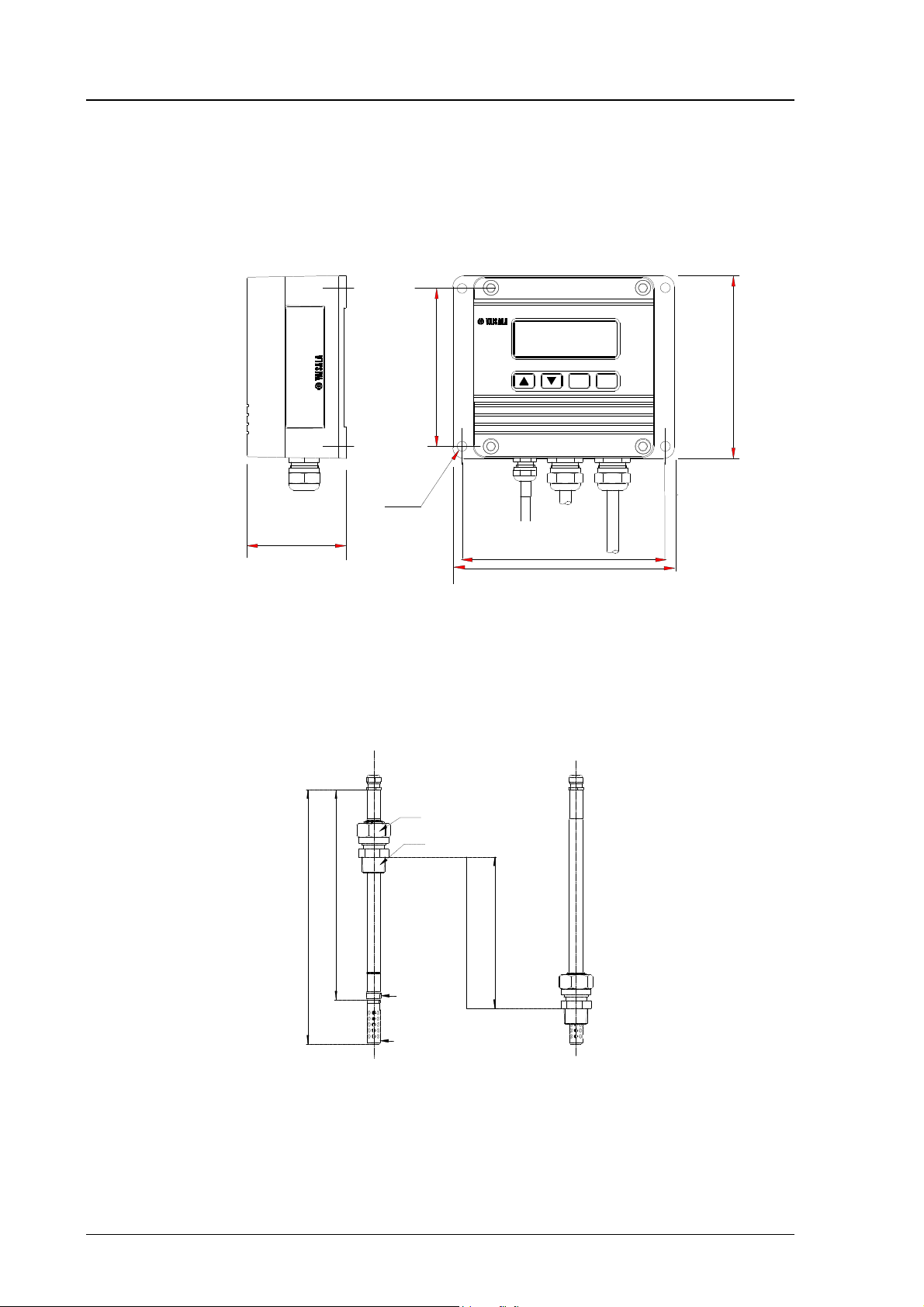
In Figures 2.2.1 and 2.2.2 you can see the dimensions of the HMP228
transmitter and probe:
104
CL
ENT
120
ø6.5
65
133
145
Figure 2.2.1 Dimensions of the HMP228 electronics housing (in mm)
Probe pushed down
Probe up
Parallel thread
Tapered thread
180 / 400
216 / 435
Ø13.5
Ø12
A:Probe 180mm adjustment
range 120mm
Probe 400mm adjustment
range 340mm
A
Figure 2.2.2 Probe dimensions (in mm).
4
Page 11
HMP228
M210282en-A Operating Manual
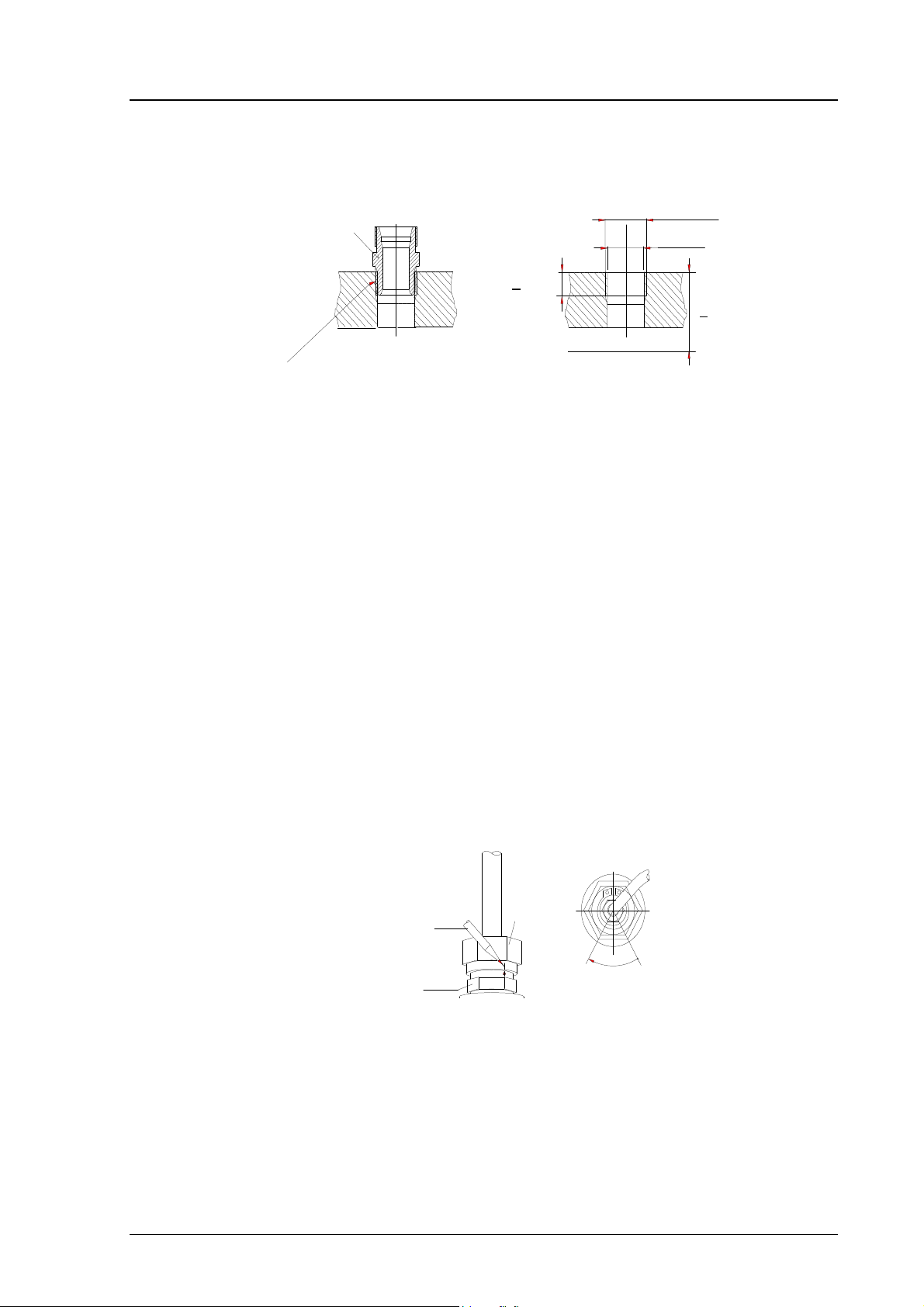
fitting body
hex = 24mm
tapered thread
R1/2 ISO 7/1
>10.5mm
sealing with:
1. LOCTITE® No 542 + activ. No 7649 (t=-55...+150 °C)
2. MEGA-PIPE EXTRA No 7188 (t=-55...+170 °C)
3. PTFE tape (t=-60...+210 °C) NOTE: the tape does not lock
the parts together . Therefore, use two fork spanners (hex 24 and
27 mm) for tightening and opening the clasp nut of the probe
Process or pipe wall
parallel thread
G1/2 ISO 228/1
(BS 2779, JIS B0202)
ø19mm drilling
>40mm
Figure 2.2.3 Sealing and thread cutting for the fitting body
The fitting body can be installed e.g. on standard pipe fittings (G 1/2 ISO
228/1) or on a thread in the process wall. If the wall thickness is less than
10.5 mm, it is recommended to use a welded sleeve (see Figure 2.2.4). Note
that the minimum recommended distance of the fitting body and the probe
head is 40 mm (see Figure 2.2.3).
Adjust the probe to a suitable distance according to the type of installation and
tighten the clasp nut first manually; mark the fitting body and the clasp nut
and tighten the clasp nut a further 50 - 60 ° with a fork spanner (see Figure
2.2.4).
Pushing the probe head through the ball valve assembly. Open and close the
ball valve assembly with the marking groove always in sight. When the probe
has been pressed through, the nut is tightened 50 - 60 ° with a fork spanner
(hexacon 27 mm).
probe
a pen
fitting body
clasp nut
60°
max.
Figure 2.2.4 Tightening the clasp nut
NOTE
Be careful not to tighten the clasp nut more than 60°
as this may result in difficulties when trying to pull
the probe head up.
5
Page 12

HMP228
Operating Manual M210282en-A
2.2.3 Installing the probe through the ball valve assembly
It is recommended that the sensor head is installed in the process through the
ball valve assembly. Use a 1/2" ball valve assembly with a hole diameter of
14 mm or more. With this installation, it is not necessary to empty or shut
down the process for installing or removing the sensor head. If the sensor head
is installed in a process pipe, please note that the nominal size of the pipe
must be at least 1 inch. See Figure 2.2.3.1. for detailed instructions.
probe
handle
>30 mm
ball of the
ball valve
(hole diameter
> 14 mm)
process pipe / chamber
Figure 2.2.3.1 Installing the sensor head through the ball valve assembly
NOTE
The probe can be installed in the process through the
ball valve assembly provided that the process pressure
is less than 10 bars. This way, the process does not have
to be shut down for installing or removing the probe.
However, if the process is shut down before removing
the probe, the process pressure can be max. 20 bars.
6
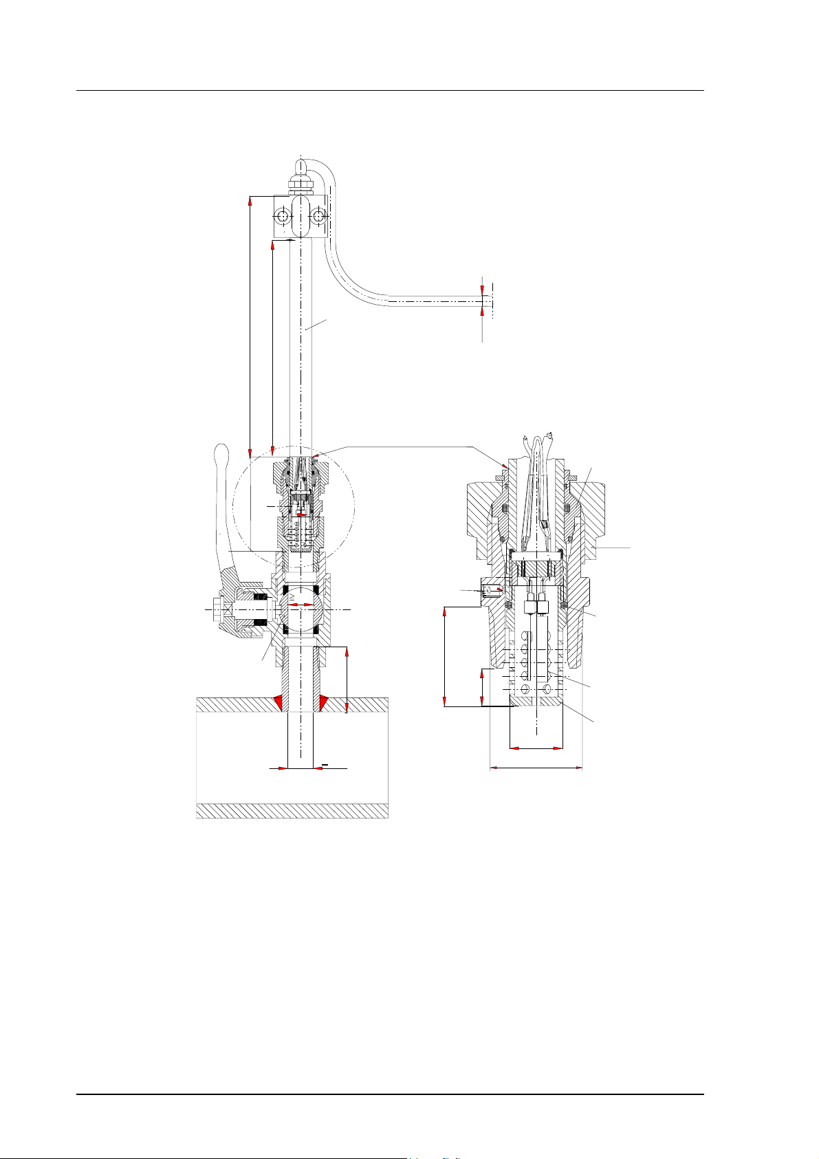
Page 13

HMP228
bushing R1/2 cone/ G1/2 (40 bar)
e.g. Camozzi 2520-1/2-1/2
(the bushing serves for
moving the probe (sinter)
so such a distance from the
ball valve that the valve
can be closed)
NOTE
tighten the clasp
nut manually
fitting body
R1/2 cone, sealed
ball valve 1/2" (40 bar)
e.g. Atlas Copco:
BAL-1A 15 (G1/2)
bushing
R1/2 cone,
sealed
nipple
R1/2 cone,
sealed
> 30 mm
welded nipple
diam. 21.3 x S
material: steel
or AISI 304L
the nipple edges have
to be rounded
s
Operating Manual
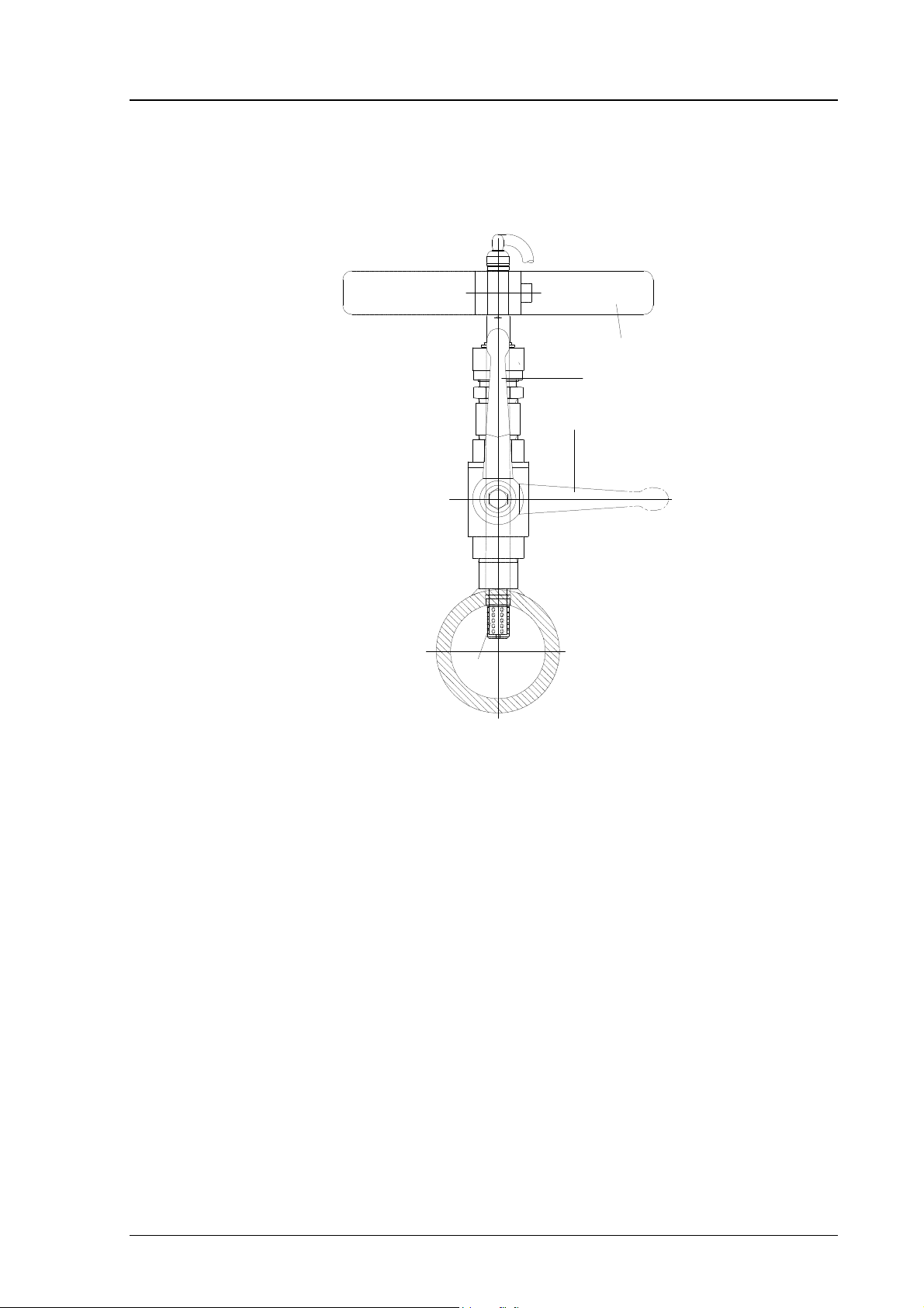
See Figures 2.2.3.2 - 2.2.3.4 for detailed description of installation through the
ball valve assembly. Note also that if the sensor head is installed in a process
pipe, the nominal size of the pipe must be at least 1 inch.
• STEP I: mount the probe with the ball valve assembly closed
Figure 2.2.3.2 Installing the probe through the ball valve
assembly; step 1
7
Page 14
HMP228
R1/2 ISO 7/1
53.6
ø5.5
adjustment range 120mm
148
ø14
(40)
>ø14
ø12
~8.5
~22.5
sintered
filter
moisture
sensor
O-ring
wedge
ring
nut
(AV=27mm)
screw A
process pipe or chamber
Operating Manual
• STEP 2: open the ball valve assembly
Figure 2.2.3.3 Installing the probe through the ball valve
assembly; step 2 (measures in mm)
The clasp nut is tightened manually prior to opening the ball valve assembly.
8
Page 15
HMP228
M210282en-A Operating Manual
• STEP 3: push the probe head through the ball valve assembly into the
process. Note that the sensor head must be pushed so deep that the filter is
completely inside the process flow.
MANUAL PRESS TOOL
VALVE OPEN
VALVE CLOSED
FILTER
Figure 2.2.3.4 Installing the probe through the ball valve
assembly: step 3
2.2.4 Mounting the probe directly in the process pipe
When the probe is installed directly in a process pipe, note that a closing valve
is needed on both sides of the installed probe so that the sensor head can be
removed from the process for calibration and maintenance.
9
Page 16

HMP228
CH1- and CH2- are connected
DO NOT USE POWER SUPPLY
Power supply
Operating Manual M210282en-A
when the probe is pulled
out for maintenance, cap
the hole with a capped nut;
this way, the process can
be open although the probe
is not in place
welded sleeve
(G1/2) or tube
with thick walls
capped nut
DIN 917-M22x1.5
sealing
probe
closing valve
(ball valve)
Figure 2.2.4 Installing the sensor head directly in a process pipe
2.3 Signal cabling and grounding
2.3.1 Electrical connections
X2
+
Ch1
Rx
Current loop or
RS485 module
Sensor connections
GND
Tx
nc
Figure 2.3.1 Electrical connections
+
Ch2
24V
+
+ Ch1 -
V
mA
--
+ 24V -
+ Ch2 -
V
mA
together internally (X2).
-
X1
GROUND (-) AS OUTPUT
SIGNAL GROUND (X1)!
10
Page 17

HMP228
common
M210282en-A Operating Manual
Power supply 24 VDC
24 VAC (see Chapter 2.3.2)
with power supply module 115/230 VAC
Output signals 0...20 mA
4...20 mA
0...1 V
0...5 V
0...10 V
Power supply ground (-) is connected to the housing with parallel connection
of 15 nF capacitor and 300 kΩ resistor.
See Appendix 3 on how to connect the power supply module to the
transmitter.
2.3.2 Connection to an AC supply
The HMP228 transmitter can also be connected to an AC supply without an
external rectifier. However, when more than one transmitter is connected for
example to one 24 VAC transformer, a common loop is formed and there is an
increased risk of a short-circuit. To avoid this, always use separate floating
supply for each transmitter (see Figure 2.3.2 A). However, if several
transmitters have to share one transformer, the phase (∼) must always be
connected to + connector in each transmitter (see Figure 2.3.2 B).
A) NO COMMON LOOP FORMED - RECOMMENDED
HMP228 transmitter Controller
24 VAC
24 VAC
HMP228 transmitter
B) COMMON LOOP FORMED -
HMP228 transmitter
signal
supply
supply
NOT RECOMMENDED!
o utput
voltage
signal
output
voltage
Controller
24 VAC
HMP228 transmitter
signal
supply
supply
output
voltage
shared
line
voltage
signal
o utp ut
Figure 2.3.2 Connecting the transmitter to an AC supply
11
Page 18
HMP228
Operating Manual M210282en-A
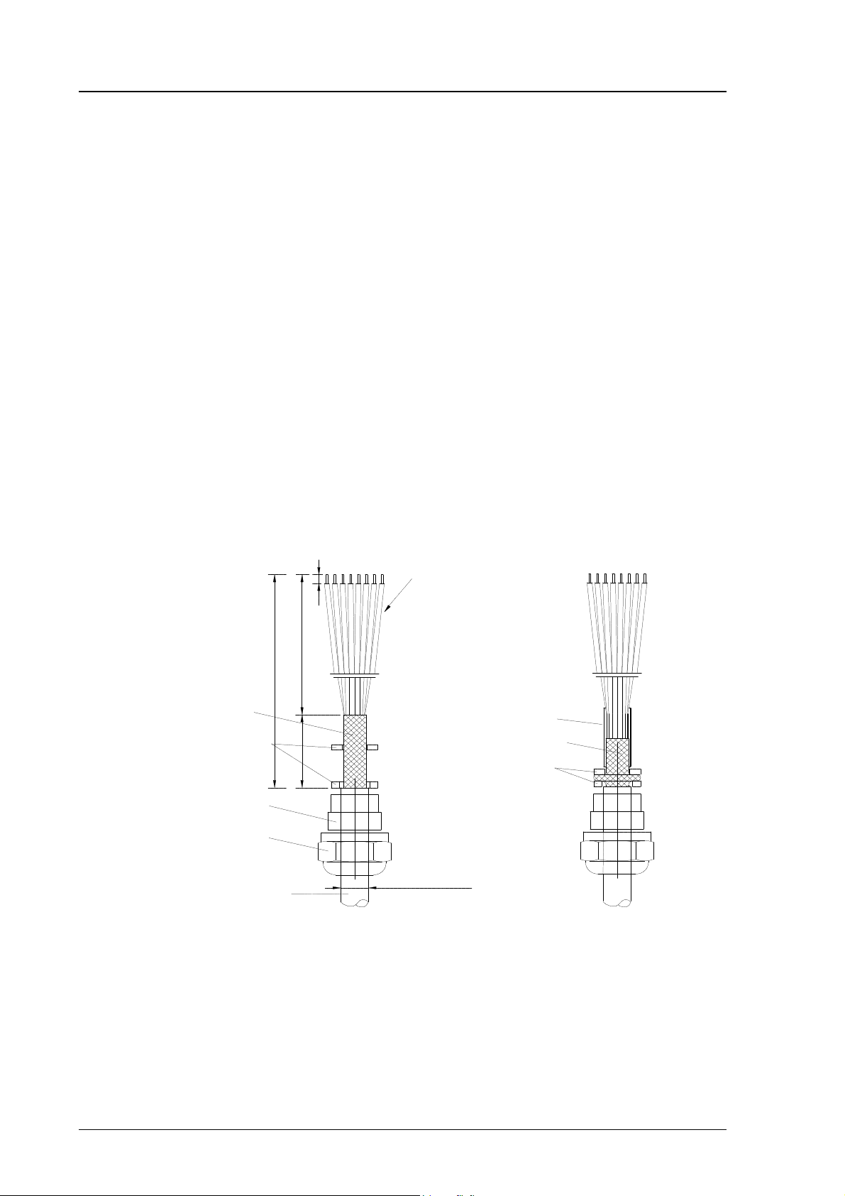
2.3.3 Grounding
A single electrical cable with a screen and three to ten wires is recommended
for power and analogue output/serial bus connections. The cable diameter
should be 7...10 mm.
The screen of the electrical cable must be grounded properly to achieve best
possible EMC performance. Recommended cable shield is done in the cable
gland as shown.
• remove the brass disks, rubber ring and nut from the transmitter
housing
• strip 165 mm of the cable insulation, but leave 25 mm of the braid
visible
• slip the nut and rubber ring over the cable insulation
• slip the brass disk that has the bigger hole in it over the braid so that
it rests against the cable insulation
• slip the other brass disk over the wires to the middle of the braid
flexible wires 0.5 mm²
(AWG 20), stranded wires
recommended
3
140
165
braid
brass
disks
rubber
ring
nut
cable
25
D = Ø 7...10 mm
(If the cable diameter is less
than 7mm, use a shrinking
tube or an adhesive tape)
shielding tube
braid
brass disks
12
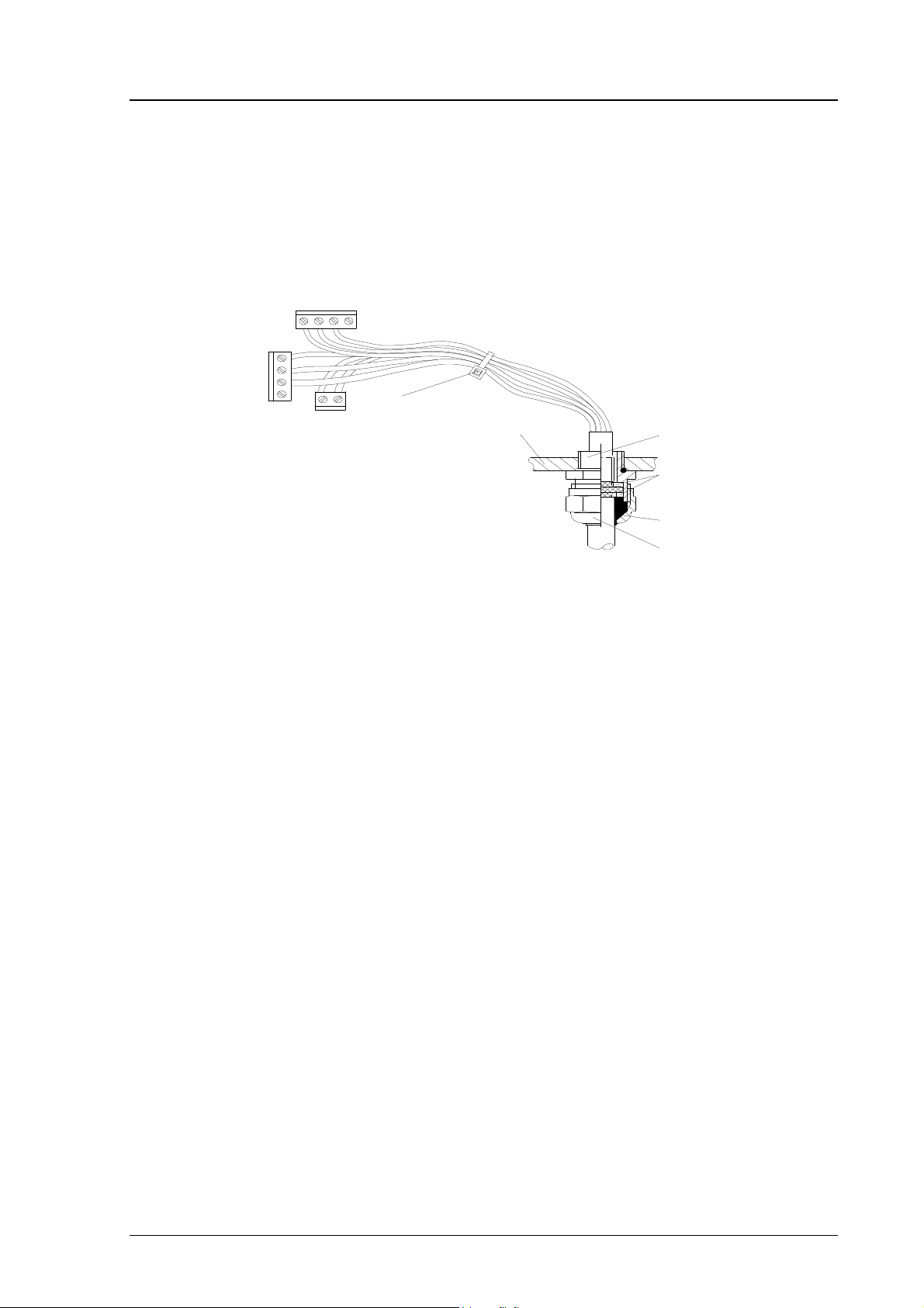
• push back the braid and press it between the two brass disks to
achieve a full 360° grounding; the fold between the disks should have
the same diameter as the brass disks
• secure the braid with a shielding tube
• insert the wires into the transmitter housing through the gland
• tighten the nut
Page 19
HMP228
M210282en-A Operating Manual
• connect the wires into the screw terminals and fasten a cable tie
around the wires
Use connectors instead of traditional cabling. See Appendix 8 for connector
types available and for detailed instructions.
cable tie
transmitter housing
gland
brass disks
rubber ring
nut
NOTE
When the cable is grounded as explained, the metallic
parts of the sensor head, the screen of its cable, the
transmitter housing and the screen of the signal cable to
external system are all connected to each other. After
this the whole system can be grounded from one point
only. If the grounding is made via several points (sensor
head, transmitter housing, signal cable), make sure that
the different groundings are made to the same
grounding potential. Otherwise harmful grounding
currents may be generated. If you do the grounding via
the transmitter housing, use one serrated lock washer
between a mounting screw and the housing; the lock
washer breaks the paint on the housing.
When mains power supply is used, ground the housing with a protective
ground wire using a grounding screw on the right side of the power supply
module (see Appendix 3 for details).
13
Page 20

HMP228
Operating Manual M210282en-A
3. COMMISSIONING
When the HMP228 transmitter leaves the factory, its measurement ranges and
output signals have already been scaled according to the order form completed
by the customer. The unit is calibrated at the factory and ready to operate
when the power is turned on. If you take into use active current, voltage or
serial bus outputs, make these connections first; appendix 9 describes them in
detail.
NOTE
Make sure that the power is not turned on until cables
have been connected to screw terminals!
In transmitters with display, the software version appears for a few seconds
when the power is turned on. After this, measurement results appear
automatically. Should an error message appear on the display, consult
Appendix 6.
If your transmitter has a blank cover and the LED indicator inside the housing
lights up, consult Appendix 6 for further information.
Appendix 7 contains information on how to determine the ranges for alarm
outputs and alarm controls when an alarm output unit is used, and Appendix 8
describes the use of connectors.
3.1 Changing the parameters
If necessary, the user can subsequently change the measurement units between
metric and non-metric and select and scale the output signals with software
functions. This is done through commands, either utilizing the menus on the
local display or giving commands through the serial interface (see
Appendices). Most often the commands are used to change the settings of the
two analogue channels.
A limited range of commands can be given with the three press switches (up,
down, enter) inside the transmitter housing. There are four LEDs to indicate
the commands given with the up and down switches. All HMP228 units
incorporate these switches and LED indicators. LED commands can be used to
calibrate the transmitters (both humidity and temperature) or to calibrate the
analogue outputs.
14
If you need to change some functions, read the following chapters carefully.
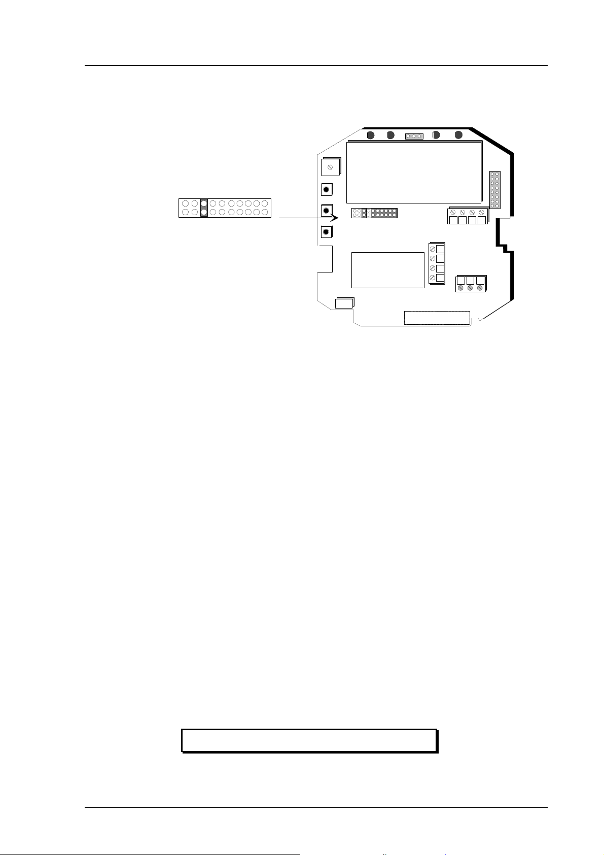
3.1.1 Security lock jumper
Before the settings can be changed, the user must first remove the security
lock jumper in connector X15 (see Figure 3.1.1). The security lock jumper
Page 21
HMP228
M210282en-A Operating Manual
makes it impossible to change the transmitter settings by mistake. The jumper
should be removed only for changing the settings and for calibration.
X15
Change of settings
disabled
Current loop or
RS485 module
Sensor connections
+
Ch1
Rx
GND
Tx
--
+
Ch2
24V
nc
-
+
Figure 3.1.1 Location of the security lock jumper
When the security lock jumper is connected, some commands cannot be used,
see Chapter 4.
If you wish to take into use variables that are not included in the configuration
of your transmitter, contact Vaisala for more information.
3.1.2 Commands and security lock jumper
In order to prevent any tampering with the transmitter settings, the transmitters
cannot be calibrated, the analogue outputs set or the analogue output
quantities selected or scaled unless the security lock jumper has been
disconnected. The commands involved are:
• serial commands: CRH, CT, FCRH, ACAL; AMODE, ASEL, ASCL
• all LED commands
• display/keypad commands:
Cali ð RH T
Analog outputs
Mode ð Analog outputs ð Mode
Scale
In the following, the description of these functions is preceded with a
reminder of the security lock jumper:
Disconnect the security lock jumper!
15
Page 22

HMP228
GND
HMP228
Operating Manual M210282en-A
3.2 Using the RS 232C serial bus
Rx GND Tx
X17
Rx
Tx
Nc
Current loop or
RS485 module
+
Ch1
X6
Rx
GND
Tx
nc
Sensor connections
+
Ch2
24V
+
--
-
Figure 3.2.1 Serial bus connections
To connect a PC to the HMP228 transmitters via the RS 232C serial bus, one
of the following cables is required. The type of cable depends on the terminal
and the connector type.
RXD
RXD
RXD
TXD
TXD
TXD
TX
GND
RX
TX
GND
RX
TX
GND
RX
PC
TERMINAL
D9S
D25S
D25P
2
5
3
4
6
7
8
3
7
2
5
6
8
20
3
7
2
Figure 3.2.2 Connection of cables
When the serial bus has been connected between the PC and the transmitter,
the PC is switched on. When using a PC, a terminal emulation programme
(e.g. Procomm Plus, Datastorm or Windows terminal) is started.
The factory settings for data transfer are:
• 4800 baud
• even parity
• 7 data bits
• 1 stop bit
• full duplex
16
Page 23

HMP228
M210282en-A Operating Manual
NOTE
When the serial bus settings are changed, the transmitter has to be reset before the new settings become effective.
The processor does not allow the following combinations:
• no parity, 7 data bits, 1 stop bit: if this combination is given the
HMP228 programme will change the number of stop bits to 2
• even or odd parity, 8 data bits, 2 stop bits: if this combination is given
the programme changes the number of stop bits to 1
Refer to the manuals of the PC and the terminal emulation programme when
giving serial settings.
The RS 232C screw terminal cannot be used if an RS 485/422 serial module
or a current loop module is used. See Appendices 3 and 4 on how to install
and operate these modules.
In calibrating or changing the settings of the transmitter it can be more convenient to use the connector X17, if connector X6 is already in use. This connector, however, transfers only RS 232C signals. If an RS 485/422 serial port
module or a current loop module has been installed, it has to be removed before communicating through the X17 connector.
NOTE
Some PC computers can generate interferences to the
measured humidity and temperature values if the
transmitter and the PC are connected to different mains
outlets. To minimize the possibility of these interferences, always use the same main outlet (same phase of
the main electricity) for the PC and the power supply of
HMP228. It is always preferable to use the connector
X16 instead of the connector X17 because it is more
immune to interferences.
The serial commands are described in Appendix 1.
17
Page 24

HMP228
Operating Manual M210282en-A
3.3 Using LED commands
NOTE
If the transmitter has a display/keypad cover, the LED
commands cannot be used.
LED commands can be used to operate the transmitters in the field. These
commands can be used in humidity and temperature calibration and calibration
of the analogue outputs.
Open the housing and press any one of the three press switches. The LEDs
will light up for 2...3 seconds.
LEDS
UP
PRESS SWITCHES
DOWN
+
ENT
Current loop or
RS485 module
Sensor connections
Ch1
Rx
GND
Tx
Figure 3.3 Location of press switches and LEDs
Use the up and down switches (marked with arrows on the printed board) to
find the desired command code and acknowledge it with the ENT switch. The
command codes are (l = lit, ¡ = dark):
¡¡¡¡ (0) return to normal state
¡¡¡l (1) relative humidity calibration
¡¡l¡ (2) temperature calibration
¡¡ll (3) calibration of analogue outputs
l¡¡l (9) forced auto-calibration (one auto-calibration; the
security lock jumper must be connected)
--
+
Ch2
24V
nc
-
+
3.4 Using display/keypad commands
3.4.1 Display mode
In the display mode the transmitters output measurements on the display; different quantities can be scrolled with the arrow keys. The first line is scrolled
18
Page 25

HMP228
M210282en-A Operating Manual
with button s and the second line with button t; all selections are stored
with ENTER. The selected quantities appear on the display also after power
failure. After reset the transmitters are always in the display mode.
The display also shows error messages and alarms if they occur.
3.4.2 Command mode
Press the CL key to enter the command mode. The first display is the main
menu:
The commands can be scrolled with the arrow keys. The currently active
command flashes; the desired command is selected with the ENT key. When a
menu is displayed, either the first command or the currently valid setting
flashes. The CL key takes the transmitter back to the display mode.
3.4.3 Entering numbers
When the transmitter needs numbers to be entered into the programme (e.g.
when scaling or setting the analogue outputs, in calibration or when giving the
transmitter an address), the field is either empty or the currently valid figure
is displayed. Any previously given value is deleted with the CL key.
When the field is empty, a cursor blinks on the right side of the display.
Pressing the arrow keys brings either a blank ( ), a comma (,), a dash (-), a full
stop (.) or a number from 0 to 9 on the display. The right character is selected
with ENT; after that the number or numbers move left one step. Entering
numbers is ended with selecting a blank ( ) and pressing ENT. The last character entered can be deleted with CL. If CL or ENT key is pressed when the field
is empty, the programme returns to the previous display.
With some commands (e.g. calibration) figures are changed using the arrow
keys. When an arrow key is pressed continuously for a while, the numbers
start changing at an increasing rate.
The display commands are described in Appendix 2.
19
Page 26

HMP228
Operating Manual M210282en-A
4. MAINTENANCE
4.1 Self-diagnostics
The HMP228 transmitter goes through a self-diagnostics procedure when the
power is switched on. If the procedure does not reveal any errors or faults, the
transmitter starts operating normally. If errors or faults are found, check first if
the moisture and temperature sensors are damaged. If they are intact, send the
transmitter to Vaisala for repairs. The error messages are listed in Appendix 3.
If any errors occur during operation, the error messages are output on the local
display if the transmitter displays measurements; if the menus are used, error
messages are not output. The LEDs indicate errors at all times. During operation, however, the error messages are not output automatically through the serial interface. If there is any reason to doubt that there is something wrong
with the transmitter, use command ERRS:
If there are no error messages, only a prompt is displayed:
>ERRS <cr>
>
When errors have occurred, the transmitter outputs the error code (see Appendix 3 for all error messages):
>ERRS <cr>
E40 f ( all ) out of range
>
4.2 Reference measurements
Reference measurements are needed to verify whether the transmitter readings
are within specifications. This way the user can check if the transmitter needs
calibration or service.
Whatever the technique used, make sure that the reference instrument is at the
same temperature as the checked instrument in order to avoid errors caused by
temperature differences. The reference measurement should be made as close
to the checked sensor as possible and the readings should be read at the same
time, when possible.
ERRS <cr>
20
Page 27

HMP228
M210282en-A Operating Manual
4.3 Moisture calibration
The HMP228 transmitter has been fully calibrated at the factory so there
should be no immediate need for recalibration. The transmitter should be
calibrated only if there is reason to believe that the adjustments have changed.
The optimal interval for moisture calibrations depends on the process and the
recommended interval varies from 3 months to 2 years.
NOTE
The HMP228 transmitter measures water activity in
liquid/oil and the calibration is performed as for relative
humidity transmitters. In calibration mode the
transmitter automatically outputs relative humidity as
the calibration parameter. It is essential to clean the
sensor surface of oil before calibration; use e.g.
instrument air or nitrogen to blow off the oil. Even the
smallest amount of oil may destroy the salt solution.
NOTE
As oil performs a membrane over the sensor surface,
the sensor's capability of absorbing moisture is slowed
down. The stabilization time is thus at least double the
time of a clean sensor; pay special attention to
controlling the stabilization time.
A two-point calibration can be performed with Vaisala’s HMK15 or HMK13B
Calibrator or the instrument can be sent to Vaisala. The instrument has to be
recalibrated each time the moisture sensor is changed.
A Ø 13.5 adapter must be used when calibrating with the HMK13B Calibrator.
The adapters (part no. 16611) can be ordered from Vaisala or Vaisala
representatives.
Calibration can be performed by giving the commands using the press
switches inside the housing, through the serial bus or through the menus on
the local display.
When LED commands are used, relative humidity is output instead of water
activity. When the transmitter is calibrated at two points, the points must be
either 50 %RH or 50 °C apart from each other.
NOTE
If the sensor has been changed, perform a calibration according to Chapter
4.4.1.
21
Page 28

HMP228
Operating Manual M210282en-A
4.3.1 Two point calibration procedure
A two point calibration should be performed in stable conditions using
saturated salt solutions as references.
Disconnect the security lock jumper!
4.3.1.1 Using serial commands
• Leave the calibrator and the transmitter for at least 4 hours in the
same space so that their temperatures have time to equalize. Remove
the filter cap on the transmitter.
• Insert the sensor head into the calibration hole of the LiCl chamber of
the humidity calibrator.
• Wait at least 30 minutes.
• Give command CRH <cr>, enter the first point value and press <cr>.
>CRH <cr>
RH : 11.9 Ref1 ? yy.y <cr>
Press any key when ready...
• If you want to see how the sensor stabilizes to the humidity in the
calibrator, enter c <cr> instead of the first reference:
RH : 11.9 Ref1 ? c <cr>
RH : 11.5 Ref1 ? c <cr>
RH : 11.5 Ref1 ? 11.3 <cr>
Press any key when ready...
• Insert the sensor head into the calibration hole of the NaCl chamber of
the humidity calibrator.
• Wait at least 30 minutes.
• Press any key and enter the second point value; press <cr>.
RH : 75.5 Ref2 ? yy.y <cr>
• The stabilization of the sensor can be monitored by entering c <cr>
instead of the reference value.
4.3.1.2 Using display/keypad commands
22
• Leave the calibrator and the transmitter for at least 4 hours in the
same space so that their temperatures have time to equalize. Remove
the filter cap on the transmitter.
• Select Cali in the main menu and then RH cal; select Not changed
and then two point calibration RH 2 point cal. Change the first point
reading with the arrow keys to correspond to the reference humidity
and press ENT; pressing an arrow once changes the reading by
0.05 %RH.
Page 29

HMP228
M210282en-A Operating Manual
4.3.1.3 Using LED commands
• Leave the calibrator and the transmitter for at least 4 hours in the
same space so that their temperatures have time to equalize. Remove
the filter cap on the transmitter.
• Connect an ammeter/voltmeter to the analogue outputs (connector
X2). Give command ¡¡¡l. At the first calibration point the LED
on the left flashes; adjust the first point (offset) with the arrow
switches to the value given in the calibration table (Chapter 4.4.5) and
press ENT switch.
• Insert the sensor head into the calibration hole of the NaCl chamber in
the humidity calibrator.
• Wait at least 30 minutes.
• Check that the reading corresponds within the desired accuracy to the
value given in the calibration table (Chapter 4.4.5). If not, adjust the
second point with the arrow switches to the correct value and press
ENT. At the second calibration point the second LED from the left
flashes.
4.3.2 One point calibration procedure
A one-point correction can be done manually in the field against an accurate
reference but it is always recommended to perform a two point calibration.
Disconnect the security lock jumper!
4.3.2.1 Using serial commands
• Make sure that the sensors of the transmitter and the reference
instrument are close to each other. Allow enough time for the sensors
to stabilize to the measurement conditions.
• Give command CRH <cr>, enter the humidity value and press <cr>.
>CRH <cr>
RH : 11.9 Ref1 ? yy.y <cr>
Press any key when ready...
• If you want to see how the sensor stabilizes to the humidity in the
calibrator, enter c <cr> instead of the first reference:
RH : 11.9 Ref1 ? c <cr>
RH : 11.5 Ref1 ? c <cr>
RH : 11.5 Ref1 ? 11.3 <cr>
Press any key when ready...
23
Page 30

HMP228
Operating Manual M210282en-A
• Press any key and press <cr> when the transmitter requests the second
point value.
RH : 75.5 Ref2 ? yy.y <cr>
4.3.2.2 Using display/keypad commands
• Make sure that the sensors of the transmitter and the reference
instrument are close to each other. Allow enough time for the sensors
to stabilize to the measurement conditions.
• Select Cali in the main menu and then RH cal; select Not changed
and then one point offset calibration RH 1 point cal. Change the
humidity reading with the arrow keys to correspond the reference
humidity and press ENT; pressing an arrow once changes the reading
by 0.05 %RH.
4.3.2.3 Using LED commands
• Make sure that the sensors of the transmitter and the reference
instrument are close to each other. Allow enough time for the sensors
to stabilize to the measurement conditions.
• Connect an ammeter/voltmeter to the analogue outputs (connector
X2). If the outputs are already connected to e.g. a process computer
and you do not want to disconnect them, the current output can be
measured at separate test points located next to connector X15 (see
the mother board).Give command ¡¡¡l. At the first calibration
point the LED on the left flashes; adjust the humidity point (offset)
with the arrow switches to the reference value. One push of a switch
changes the output by 0.05 %RH; the change of the output voltage or
current depends on the output scaling. Press ENT switch. The second
LED from the left starts flashing; press ENT again.
4.4 Changing the moisture sensor
Remove the damaged sensor and insert a new one. Handle the sensor by the
plastic socket. DO NOT TOUCH THE SENSOR PLATE. After sensor change,
the moisture calibration must be performed according to the instructions in
section 4.4.1.
24
Page 31

HMP228
M210282en-A Operating Manual
4.4.1 Calibration procedure after sensor change
Humidity calibration should be performed in stable conditions using saturated
salt solutions as a reference.
Disconnect the security lock jumper!
4.4.1.1 Using serial commands
• Leave the calibrator and the transmitter for at least 4 hours in the
same space so that their temperatures have time to equalize. Remove
the filter cap on the transmitter.
• Insert the sensor head into the calibration hole of the LiCl chamber of
the humidity calibrator.
• Wait for 30 minutes.
• Give command FCRH <cr>, enter the first point value and press <cr>:
>FCRH <cr>
RH: 11.9 Ref1 ? yy.y <cr>
Press any key when ready...
• The stabilization of the sensor to the reference humidity can be
monitored by giving c <cr>:
RH: 11.9 Ref1 ? c <cr>
RH: 11.5 Ref1 ? c <cr>
RH: 11.5 Ref1 ? 11.3 <cr>
Press any key when ready...
• Insert the sensor head into the calibration hole of the NaCl chamber of
the humidity calibrator.
• Wait for 30 minutes.
• Press any key, enter the second point value and press <cr>:
RH: 75.5 Ref2 ? yy.y <cr>
• The stabilization of the sensor can be monitored by entering c <cr>
instead of the reference value.
4.4.1.2 Using display/keypad commands
• Leave the calibrator and the transmitter for at least 4 hours in the
same space so that their temperatures have time to equalize. Remove
the filter cap on the transmitter.
• Insert the sensor head into the calibration hole of the LiCl chamber of
the humidity calibrator.
• Wait for 30 minutes.
25
Page 32

HMP228
Operating Manual M210282en-A
• Select Cali in the main menu and then RH cal; select Sensor
changed. Change the first point reading with the arrow keys and
press ENT.
• Insert the sensor head into the calibration hole of the NaCl chamber of
the humidity calibrator.
• Wait at least 30 minutes.
• If necessary, change the second point reading with the arrow keys and
press ENT.
4.4.1.3 Using LED commands
• Leave the calibrator and the transmitter for at least 4 hours in the
same space so that their temperatures have time to equalize. Remove
the filter cap on the transmitter. '
• Insert the sensor head into the calibration hole of the LiCl chamber of
the humidity calibrator.
• Wait for 30 minutes.
• Connect an ammeter/voltmeter to the analogue outputs (connector
X2). Give command l¡¡¡. At the first calibration point the LED
on the left flashes; adjust the first point (offset) with the arrow
switches to the value given in the calibration table (Chapter 4.4.5) and
press ENT switch.
• Insert the sensor head into the calibration hole of the NaCl chamber in
the humidity calibrator.
• Wait at least 30 minutes.
• Check that the reading corresponds within the desired accuracy to the
value given in the calibration table (Chapter 4.4.5). If not, adjust the
second point with the arrow switches to the correct value and press
ENT. At the second calibration point the second LED from the left
flashes.
The basic capacitance of the new sensor may differ considerably from that of
the previous one. Therefore, the corresponding humidity reading of the
transmitter may be below 0 %RH at the low or above 100 %RH at the high
calibration point. However, the current/voltage reading of the analogue output
shows only the minimum or maximum value of the selected current/voltage
scale and the output value may not change even though the arrow switches are
pressed several times. If this happens, press the up or down arrow switch
continuously to bring the output back into the selected scale; this may take as
long as half a minute.
26
Page 33

HMP228
M210282en-A Operating Manual
4.4.5 Humidity calibration table
Temperature °C 15 20 25 30 35
°F 59 68 77 86 95
LiCl %RH * 11.3 11.3 11.3 11.3
4...20 mA 5.81 5.81 5.81 5.81
0...20 mA 2.26 2.26 2.26 2.26
0...1 V 0.113 0.113 0.113 0.113
0...5 V 0.565 0.565 0.565 0.565
0...10 V 1.13 1.13 1.13 1.13
NaCl %RH 75.6 75.5 75.3 75.1 74.9
4...20 mA 16.10 16.08 16.05 16.02 15.98
0...20 mA 15.12 15.10 15.06 15.02 14.98
0...1 V 0.756 0.755 0.753 0.751 0.749
0...5 V 3.780 3.775 3.765 3.755 3.745
0...10 V 7.56 7.55 7.53 7.51 7.49
Table 1 Greenspan's calibration table
*) If the LiCl solution is used or stored in temperatures below +18 °C (+64 °F), the
equilibrium humidity of the salt solution changes permanently.
4.6 Temperature calibration
The temperature channel has been calibrated at the factory and since it is very
stable, adjustment should be made only when there is strong reason to believe
that the adjustments have changed.
Temperature calibration should be performed against some accurate
temperature reference. It can be done either using the press switches inside the
housing, through the serial bus or the menus on the local display. Either a one
point offset correction or a two point calibration is possible.
Disconnect the security lock jumper!
4.6.1 One point offset correction
4.6.1.1 Using serial commands
• Leave the reference instrument and the transmitter for at least 4 hours
in the same space so that their temperatures have time to equalize.
Remove the filter cap prior to calibration.
• Check the transmitter against the reference.
• Give command CT <cr>, enter the first point value and press <cr>:
>CT <cr>
T : 0.90 Ref1 ? yy.y <cr>
Press any key when ready
• If you want to see how the sensor stabilizes to the reference
temperature, enter c <cr> instead of the first reference:
27
Page 34

HMP228
Operating Manual M210282en-A
T : 0.90 Ref1 ? c <cr>
T : 0.55 Ref1 ? c <cr>
T : 0.55 Ref1 ? 0.0 <cr>
Press any key when ready...
• After giving the correct temperature value (Ref1) and pressing <cr>
press any key and then <cr>.
4.6.1.2 Using display/keypad commands
• Leave the reference instrument and the transmitter for at least 4 hours
in the same space so that their temperatures have time to equalize.
Remove the filter cap prior to calibration.
• Check the transmitter against the reference.
• Select Cali in the main menu and then T cal; select one-point
calibration T 1 point cal.
• Change the reading with the arrow keys to correspond to the reference
and press ENT.
4.6.1.3 Using LED commands
• Leave the reference instrument and the transmitter for at least 4 hours
in the same space so that their temperatures have time to equalize.
Remove the filter cap prior to calibration.
• Check the transmitter against the reference.
• Connect an ammeter/voltmeter to the analogue outputs (connector
X2). Give command ¡¡l¡. At the first calibration point the LED
on the left flashes; adjust the first point (offset) with the arrow
switches to the same reading with the reference and press ENT
switch.
• After adjusting the offset point and pressing ENT the second LED
from left flashes. Press ENT without changing the output value.
4.6.2 Two point temperature calibration
Disconnect the security lock jumper!
4.6.2.1 Using serial commands
28
• Leave the reference instrument and the transmitter for at least 4 hours
in the same space so that their temperatures have time to equalize.
Remove the filter cap prior to calibration.
• Check the transmitter against the reference.
• Give command CT <cr>, enter the first point value and press <cr>:
>CT <cr>
T : 0.90 Ref1 ? yy.y <cr>
Press any key when ready
Page 35

HMP228
M210282en-A Operating Manual
• If you want to see how the sensor stabilizes to the reference
temperature, enter c <cr> instead of the first reference:
T : 0.90 Ref1 ? c <cr>
T : 0.55 Ref1 ? c <cr>
T : 0.55 Ref1 ? 0.0 <cr>
Press any key when ready...
• Change the temperature and again check the transmitter against the
reference.
• Check that the reading corresponds with the reading of the reference
instrument. If not, adjust the second point.
• Press any key, enter the second point value and press <cr>.
T : 20.0 Ref2 ? yy.y <cr>
• The stabilization of the sensor can be monitored well by entering c
<cr> instead of the reference value.
4.6.2.2 Using display/keypad commands
• Leave the reference instrument and the transmitter for at least 4 hours
in the same space so that their temperatures have time to equalize.
Remove the filter cap prior to calibration.
• Check the transmitter against the reference.
• Select Cali in the main menu and then T cal; select two-point
calibration T 2 point cal. Change the first point reading with the
arrow keys and press ENT.
• Change the temperature and again check the transmitter against the
reference.
• Check that the reading corresponds with the reading of the reference
instrument. If not, adjust the second point.
• If necessary, change the second point reading with the arrow keys and
press ENT.
4.6.2.3 Using LED commands
• Leave the reference instrument and the transmitter for at least 4 hours
in the same space so that their temperatures have time to equalize.
Remove the filter cap prior to calibration.
• Check the transmitter against the reference.
• Connect an ammeter/voltmeter to the analogue outputs (connector
X2). Give command ¡¡l¡. At the first calibration point the LED
on the left flashes; adjust the first point (offset) with the arrow
switches to the same reading with the reference and press ENT
switch.
• Change the temperature and again check the transmitter against the
reference.
29
Page 36

HMP228
Operating Manual M210282en-A
• Check that the reading corresponds with the reading of the reference
instrument. If not, adjust the second point.
• If necessary, adjust with the arrow switches to the correct value and
press ENT. At the second calibration point the second LED from the
left flashes.
4.6.3 Temperature channel adjustment with Pt 100 simulators
Switch the power off and disconnect the wires to the Pt 100 sensor from solder
lugs TP5, TP6 and TP7.
TP6
X88
TP7
TP5
Figure 4.6.3.1 Location of solder lugs TP5, TP6 and TP7 and
connector X88
Connect a Pt 100 simulator to connector X88 and set it at the lowest temperature to be calibrated.
Pt 100
X88
Figure 4.6.3.2 Connecting the Pt 100 simulator to connector X88
Switch the power on. Follow the one or two point calibration instructions in
Chapters 4.6.1 - 4.6.2.
30
Switch the power off. Disconnect the Pt 100 simulator and reconnect the Pt
100 wires to solder lugs TP5, TP6 and TP7.
The correct connections according to the wire colours are:
TP5 TP6 TP7 TP8
blue green yellow black
If there is not a Pt 100 simulator available, the adjustment can be made with
two resistors of 84 Ω and 154 Ω whose resistance is known precisely. Measure
the resistor with a resistance meter. Look up the corresponding temperature
value from a Pt 100 conversion table or calculate it using the following
equation:
Page 37

HMP228
jumpers
M210282en-A Operating Manual
T = D0 +R x {D1 + R x [D2 + R x (D3 + R x D4)]}
where
D0 = -243.5673014
D1 = 2.278542701
D2 = 0.002050681
D3 = -6.15025E-06
D4 = 1.34949E-08
4.7 Analogue output channels
4.7.1 Setting the analogue outputs
The HMP228 transmitters can be ordered with the required current or voltage
outputs already selected. If the outputs need to be changed, move the jumpers
in connector X15 into positions as shown in Figure 4.7.1.2.
Spare
+
X55
Current loop or
RS485 module
Sensor connections
Ch1
Rx
GND
Tx
Figure 4.7.1.1 Spare jumpers
--
+
Ch2
24V
nc
-
+
31
Page 38

HMP228
Operating Manual M210282en-A
Ch2
Ch1
Ch2
Ch1
Current outputs
0... 20/4... 20 mA
Ch2
Ch1
Ch2
Ch1
Voltage outputs
0... 5/0... 10 V
X15
+
Ch1
+
Ch2
--
Ch2
Ch1
Ch2
Ch1
Ch1
Ch1
Ch2
Voltage outputs
0... 1 V
Ch2
Ch1 0... 1 voltage ouput
Current loop or
RS485 module
Sensor connections
Rx
GND
Tx
24V
nc
-
+
Ch 2 current output
Figure 4.7.1.2 Selecting the analogue outputs with jumpers
All jumpers are used only with the 0...1 V outputs. When other outputs are in
use, the spare jumpers are kept in connector X55.
4.7.1.1 Using serial output
Disconnect the security lock jumper!
AMODE a bb.bbb cc.ccc d ee.eee ff.fff <cr>
a = channel 1: U = voltage output I = current output
bb.bbb = lower limit of channel 1
cc.ccc = upper limit of channel 1
d = channel 2: U = voltage output I = current output
ee.eee = lower limit of channel 2
ff.fff = upper limit of channel 2
32
The bb.bbb, cc.ccc, ee.eee and ff.fff parameters are entered in volts or
milliamperes.
Example: lower limit of channel 1 is 0 V and upper limit 1 V (U 0 1)
lower limit of channel 2 is 2 V and upper limit 10 V (U 2 10)
>AMODE U 0 1 U 2 10 <cr>
Ch1 : 0.000 ... 1.000 V
Ch2 : 2.000 ... 10.000 V
Page 39

HMP228
M210282en-A Operating Manual
4.7.1.2 Using display/keypad commands
Disconnect the security lock jumper!
• Select Mode in the main menu and Analog outputs in the Mode
menu:
• Select Mode (ma/V). The current settings for channel 1 are displayed:
• If the settings are correct, press ENT.
• If the settings need to be changed, press CL:
- the quantity (mA/V) starts flashing; it can be changed with the arrow
key and acknowledged with ENT
- the lower limit starts flashing
- acknowledge the lower limit with ENT or start changing it by pressing
CL; a new lower limit is given one character at a time with the arrow
keys
- the upper limit starts flashing
- acknowledge the upper limit with ENT or start changing it by pressing
CL; a new upper limit is given one character at a time with the arrow
keys
When channel 1 has been set, the programme goes on to channel 2; the
procedure is the same as with channel 1.
33
Page 40

HMP228
Operating Manual M210282en-A
4.7.2 Selecting and scaling the analogue output quantities
Disconnect the security lock jumper!
4.7.2.1 Using serial output
ASEL xxx yyy <cr>
xxx = channel 1's quantity
yyy = channel 2's quantity (Aw, T)
Example: water activity is selected on channel 1 and temperature on
channel 2
>ASEL aw T <cr>
Ch1 (aw) lo 0.000 aw ? <cr>
Ch1 (aw) hi 1.000 aw ? <cr>
Ch2 (T ) lo -40.000 'C ? <cr>
Ch2 (T ) hi +160.000 'C ? <cr>
ASCL <cr>
Example: water activity is scaled on the range of 0...1 Aw and temperature
0...+100 °C
>ASCL <cr>
Ch1 (Aw) lo 0.000 Aw ? <cr>
Ch1 (Aw) hi 1.000 Aw ? <cr>
Ch2 (T ) lo -40.000 'C ? 0 <cr>
Ch2 (T ) hi 160.000 'C ? 100 <cr>
4.7.2.2 Using display/keypad commands
Disconnect the security lock jumper!
• Select Mode in the main menu and Analog outputs in the Mode
menu:
34
• Select Scale. The quantity and scaling for channel 1 are displayed:
• If the settings are correct, press ENT.
Page 41

HMP228
M210282en-A Operating Manual
• If the settings need to be changed, press CL:
− the quantity (aw, T) starts flashing; it can be changed with the
arrow keys and acknowledged with the ENT key
− the lower limit starts flashing
− acknowledge the lower limit with ENT or start changing it by
pressing CL; a new lower limit is given with the arrow keys
− the upper limit starts flashing
− acknowledge the upper limit with ENT or start changing it by
pressing CL; a new upper limit is given with the arrow keys
• When channel 1 has been set, the programme goes on to channel 2;
the procedure is the same as with channel 1.
4.8 Checking and calibrating the analogue outputs
The operation of analoque outputs can be tested by forcing the outputs to
given values. See on appendix n. ITEST command.
4.8.1 Measurement of output currents using test points
If a current output has been connected e.g. to a process computer, the output
current cannot be measured at the output connector X2 without disconnecting
the external load. The output current can, however, be measured at test points
CH1+/CH1- and CH2+/CH2- without disconnecting the output wires. These
test points can therefore be used in one point offset correction against an accurate reference or in checking the current output without disconnecting the
analogue output from the process.
35
Page 42

HMP228
Operating Manual M210282en-A
+
-
+
Current loop or
RS485 module
Ch1
-
Ch2
X15
X2
+
Ch1
Rx
GND
Tx
nc
Sensor connections
+
Ch2
24V
+
--
-
Figure 4.8.1.1 Location of the CH1 and CH2 test points
mA
X2
CH1+
CH1+
TEST POINTS
CH1-
CH1-
R
L
Figure 4.8.1.2 Circuit diagram of the analogue output current test
points.
4.8.1 Calibration of the analogue outputs
The analogue outputs have been calibrated at the factory and since they are
very stable, calibration of the outputs should be performed only when there is
reason to believe that their adjustments have changed.
Disconnect the security lock jumper!
36
Page 43

HMP228
M210282en-A Operating Manual
4.8.1.1 Using serial commands
ACAL <cr>
The outputs on channels 1 and 2 are measured and the measured values (mA
or V) entered as calibration coefficients.
Example: both channels have 0...10 V outputs (set with AMODE command);
enter the voltages measured at the analogue outputs:
>ACAL <cr>
Ch1 U1 ( V ) ? 0.123 <cr>
Ch1 U2 ( V ) ? 9.980 <cr>
Ch2 U1 ( V ) ? 0.120 <cr>
Ch2 U2 ( V ) ? 9.980 <cr>
4.8.1.2 Using display/keypad commands
• Connect an ammeter/voltmeter to the output of channel 1, select Cali
in the main menu and Analog outputs in the Cali menu. The following is displayed (the quantity can be either mA or V):
• Enter the measured lower end current/voltage on channel 1.
• Enter the measured upper end current/voltage on channel 1.
• Connect the meter to the output of channel 2 and enter the measured
lower end current/voltage on channel 2.
• Enter the measured upper end current/voltage on channel 2.
37
Page 44

HMP228
Operating Manual M210282en-A
4.8.1.3 Using LED commands
If both the analogue outputs and humidity/temperature channels are calibrated,
the analogue outputs should be calibrated first. This applies only when the
calibrations are made using the LED commands!
• connect an ammeter/voltmeter to the analogue outputs (connector X2)
• Give command ¡¡ll.
• the LED on the left flashes; set the low end of channel 1 with the ar-
row keys and press ENT
• the second LED from the left flashes; set the high end of channel 1
with the arrow keys and press ENT
• the LED on the left flashes; set the low end of channel 2 with the ar-
row keys and press ENT
• the second LED from the left flashes; set the high end of channel 2
with the arrow keys and press ENT
The analogue outputs are calibrated to ensure that outputs are correctly scaled:
for example, when the output is scaled to 4...20 mA, the low end of the scale
is 4 mA and high end 20 mA exactly. However, when 0... 20 mA output is
used, the output cannot be adjusted to exactly 0 mA, but to 50 µA. When 0...1
V, 0...5 V or 0...10 V output is in use, the output is adjusted to 50 mV. The
following table summarizes the correct output values.
low end: 50 µA 4 mA 50 mV 50 mV 50 mV
high end: 20 mA 20 mA 1 V 5 V 10 V
4.9 Other functions
4.9.1 Adjusting the contrast of the display
The contrast of the display can be adjusted using the trimmer "LCD display
contrast" located next to the press switches.
Summary of the correct output values:
Output scale:
0...20 mA 4...20 mA 0...1 V 0...5 V 0...10 V
38
4.9.2 Reverting to factory settings of the serial port
If the serial port settings are not known, no commands can be given via the
serial interface. The settings can be reverted to the factory settings by inserting
a jumper in connector X16. The jumper must be inserted when the power is
on!
Page 45

HMP228
M210282en-A Operating Manual
X16
Current loop or
RS485 module
+
Ch1
Rx
GND
Tx
Sensor connections
--
+
Ch2
24V
nc
-
+
Figure 4.9.2 Forcing the serial port settings back to factory settings
When the jumper is inserted the serial line factory settings become valid, but
only temporarily. The transmitter must be given new settings; otherwise
the transmitter uses the old, unknown settings after power-up. When the
new settings have been given, the transmitter must be reset. The jumper must
be removed before the transmitter is reset; if the jumper is in place when
power is turned on, the transmitter does not work.
After jumper insertion the transmitter is in STOP mode, ready to receive
commands.
The same method is used when the transmitter is in POLL mode and the user
has forgotten its address.
CAUTION
Inserting a jumper in any other place in connector X16
voids the guarantee of the transmitter.
39
Page 46

HMP228
Operating Manual M210282en-A
5. TECHNICAL DATA
5.1 Water activity
Measuring range of water activity 0...1
Accuracy (including nonlinearity and repeatability)
maximum achievable accuracy when calibrated against high quality,
when calibrated against salt solutions (ASTM E104-85):
±0.02 (0...0.9)
±0.03 (0.9...1.0)
maximum achievable accuracy when calibrated against high-quality,
certified humidity standards:
±0.01 (0...0.9)
±0.02 (0.9...1.0)
Response time (90 %) at +20 °C in
still oil (stainless steel filter) 10 min
Sensor HUMICAP
5.2 Temperature
Measuring range -40...+180 °C
Typical accuracy of electronics at ± 0.1 °C
+20 °C (+68 °F)
Typical temperature dependence of ± 0.005 °C/°C
electronics
Temperature sensor Pt 100 IEC 751 1/3 class B
5.4 Outputs
thin film polymer sensor
(part no. 19525HM)
(part no. 10429)
40
Two analogue outputs selectable 0...20 mA 4...20 mA
0...1 V 0...5 V
0...10 V
Typical accuracy of analogue output ± 0.05 % full scale
at +20 °C
Typical temperature dependence of 0.005 %/°C full scale
analogue output
Serial output RS232C
Page 47

HMP228
M210282en-A Operating Manual
5.5 Electronics
User interface 3 keys and 4 LEDs inside the
housing or local display keypad
Display 2 x 16 character alphanumeric
high-contrast, wide view angle
LCD
character height 3.85 mm (0.15")
Keyboard 1 x 4 keypad
Connections screw terminals, 0.5 mm2 wires
(AWG 20), stranded wires
recommended
Operating voltage 24 VDC / isolated 24 VAC
(20...28 V)
option 115/230 VAC with power supply
module
Power consumption 100 mA maximum (24 VDC)
of the alarm relays 55 mA max (24 VDC)
Recommended external load for
current outputs <500 Ω
0...1 V voltage output >2 kΩ (to ground)
0...5 and 0...10 V voltage outputs >10 kΩ (to ground)
Operating temperature (electronics) -40...+60 °C
with display cover 0...+50 °C
with power supply module -40...+45 °C
with alarm outputs up to 8A -40...+45 °C
with alarm outputs up to 6A -40...+60 °C
Storage temperature -40...+70 °C
Pressure range of the HMP228 0...40 bar
sensor head
5.6 Mechanics
Housing material G-AlSi12 (DIN 1725)
Housing classification IP 65 (NEMA 4)
41
Page 48

HMP228
Operating Manual M210282en-A
Bushing for 7...10 mm diameter cable
(8 x 0.5 mm2 shielded cable)
Sensor protection Stainless steel filter
(part no. HM46999)
Housing dimensions 145 x 120 x 65 mm
Sensor head dimensions (see Figure) length 170 mm, Ø 13.5 mm:
Probe pushed down
180 / 400
216 / 435
Parallel thread
Tapered thread
Ø13.5
A:Probe 180mm adjustment
Ø12
range 120mm
Probe 400mm adjustment
range 340mm
A
Probe up
Cable diameter 5.5 mm
Weight (without display cover and power supply module):
With 2 m cable 1300 g
With 5 m cable 1600 g
With 10 m cable 2100 g
42
Weight of display cover 420 g
Weight of power supply module 240 g
Page 49

HMP228
M210282en-A Operating Manual
5.7 Electromagnetic compatibility
The emission and immunity tests have been performed according to
thestandard EN61326-1:1997+Am1:1998; Industrial environment.
5.7.1 Emissions
Test: Setup according to:
Radiated emissions EN 55022/CISPR 22 (class B)
With power supply unit (HMP230PW):
Conducted emissions EN 55022/CISPR 22 (class B)
Harmonic currents EN/ IEC 61000-3-2
Voltage fluctuations EN/ IEC 61000-3-3
5.7.2 Immunity
Test: Setup according to:
Electrostatic discharge EN/ IEC 61000-4-2
Electrical fast transients EN/ IEC 61000-4-4
Radiated immunity EN/ IEC 61000-4-3
Conducted immunity EN/ IEC 61000-4-6
Voltage proof, AC: DC supply (+ or -) to housing 250 VAC, 1 minute (300 kΩ
and 15 nF parallel)
43
Page 50

HMP228
Operating Manual M210282en-A
6. OPTIONS
Power supply module
Operating voltage 115 VAC (93...127 V)
230 VAC (187...253 V)
Serial interface RS485/422 module HMP230RS
current loop module HMP230CL
Cable length 2, 5 or 10 metres
Display cover cover with or without local
display & keypad
Connectors for supply, signal, RS232C
and RS485 lines see Appendix 8 for details
Ball valve set DMP248BVS
Alarm output unit DMP240ALSP;2 pcs 8A/230 V
CPCO (single pole change over)
7. SPARE PARTS
Order code Description
19525HM Moisture sensor
HM46999 Stainless steel filter, outer thread
HM47453 Stainless steel filter, inner thread
5237 Fuse 160 mA T 5x20 mm for power supply module
17143 Fuse 8A for alarm output unit
16611 Calibration adapter for the HMK15 Calibrator
for adjustable low and high alarm
44
Page 51

HMP228 Transmitters
M210282en-A Appendix 1: Serial commands
APPENDIX 1: SERIAL COMMANDS
1. ANALOGUE OUTPUT COMMANDS...................................................................................... 46
AMODE Setting the analogue outputs ..................................................................... 46
ASEL Selecting the scaling the analogue output quantities ...................................... 46
ASCL Scaling the analogue outputs ........................................................................ 47
2. CALIBRATION COMMANDS................................................................................................. 49
CRH Relative humidity calibration .......................................................................... 49
FCRH Relative humidity calibration after sensor change .........................................49
CT Temperature calibration.................................................................................... 50
ACAL Calibrating the analogue outputs................................................................... 51
L Outputting linear correction coefficients............................................................... 51
LI Entering linear correction coefficients ................................................................. 51
3. OUTPUT VIA THE SERIAL BUS............................................................................................ 52
R Starting the measurement output........................................................................ 52
S Stopping the measurement output ...................................................................... 52
SEND Outputting a reading once............................................................................. 53
DSEND Outputting readings of all connected transmitters once ..............................53
ERRS Outputting error messages ........................................................................... 53
ECHO Turning the serial interface echo ON/OFF.................................................... 54
INTV Setting the output interval for the RUN state.................................................. 54
FORM Setting the output format .............................................................................. 55
FTIME Adding time to output................................................................................... 56
FDATE Adding date to output .................................................................................. 56
SERI Serial bus settings......................................................................................... 57
UNIT Selecting the output units.............................................................................. 58
ADDR Setting the transmitter address ..................................................................... 58
RESET Resetting the transmitter............................................................................. 59
3.1 Operation modes ........................................................................................................ 59
SMODE Setting the serial interface......................................................................... 59
OPEN & CLOSE...................................................................................................... 60
4. OTHERS................................................................................................................................ 61
ITEST Testing the analogue outputs ....................................................................... 61
MTIM Setting the measurement integration time ..................................................... 62
PRES Setting the pressure for mixing ratio calculations ..........................................62
XPRES Setting the pressure for mixing ratio calculations temporarily...................... 63
CDATE Entering calibration date............................................................................. 63
DATE Setting the date............................................................................................. 63
TIME Setting the time.............................................................................................. 64
VERS Name and version of the programme............................................................ 64
? Outputting the transmitter settings....................................................................... 64
?? Outputting the transmitter settings also in POLL mode...................................... 64
FILT Setting the averaging time ............................................................................. 65
The commands function as described when the serial interface is in fullduplex mode and echo is on. All commands except FORM can be given in
either capital or small letters.
In the commands <cr> means carriage return, <lf> line feed and <ht> horizontal tabulation.
45
Page 52

HMP228 Transmitters
Appendix 1: Serial commands M210282en-A
ANALOGUE OUTPUT COMMANDS
AMODE Setting the analogue outputs
Disconnect the security lock jumper!
AMODE a bb.bbb cc.ccc d ee.eee ff.fff <cr>
a = channel 1: U = voltage output
I = current output
bb.bbb = lower limit of channel 1
cc.ccc = upper limit of channel 1
d = channel 2: U = voltage output
I = current output
ee.eee = lower limit of channel 2
ff.fff = upper limit of channel 2
The bb.bbb, cc.ccc, ee.eee and ff.fff parameters are entered in volts or milliamperes.
Sets the analogue outputs on channels 1 and 2. An example: the voltage output
on channel 1 is set to be 0...1 V and channel 2 set to 2...10 V:
>AMODE U 0 1 U 2 10 <cr>
Ch1 : 0.000 ... 1.000 V
Ch2 : 2.000 ... 10.000 V
The current settings can be checked by giving the command without any parameters:
>AMODE <cr>
Ch1 : 0.000 ... 20.000 mA
Ch2 : 0.000 ... 20.000 mA
ASEL Selecting the scaling the analogue output quantities
Disconnect the security lock jumper!
ASEL xxx yyy <cr>
46
xxx = channel 1's quantity
yyy = channel 2's quantity (aw, T)
Page 53

HMP228 Transmitters
M210282en-A Appendix 1: Serial commands
For example, water activity is selected to be output on channel 1 and temperature on channel 2; the temperature range is scaled to 0...100 °C:
>ASEL RH T <cr>
Ch1 (aw) lo 0.000 ? <cr>
Ch1 (aw) hi 1.000 ? <cr>
Ch2 (T ) lo -40.000 'C ? 0 <cr>
Ch2 (T ) hi +160.000 'C ? 100 <cr>
When the ASEL command is given on its own, the transmitter outputs its current settings:
>ASEL <cr>
Ch1 (aw) lo 0.000
Ch1 (aw) hi 1.000
Ch2 (T ) lo -40.000 'C
Ch2 (T ) hi +160.000 'C
The outputs and their scales can also be given directly with the ASEL command.
ASEL xxx yyy aaa.a bbb.b ccc.c ddd.d <cr>
xxx = channel 1's quantity
yyy = channel 2's quantity
aaa.a = lower limit of channel 1
bbb.b = upper limit of channel 1
ccc.c = lower limit of channel 2
ddd.d = upper limit of channel 2
ASCL Scaling the analogue outputs
Disconnect the security lock jumper!
ASCL <cr>
Scales the outputs selected on channels 1 and 2.
For example, scaling water activity on the range of 0...1.00 and temperature -
40...+160 °C:
>ASCL <cr>
Ch1 (aw) lo 0.000 ? <cr>
Ch1 (aw) hi 1.000 ? <cr>
Ch2 (T ) lo 0.000 'C ? -40 <cr>
Ch2 (T ) hi 100.000 'C ? 160 <cr>
47
Page 54

HMP228 Transmitters
Appendix 1: Serial commands M210282en-A
The output scales can also be given directly with the ASCL command.
ASCL aaa.a bbb.b ccc.c ddd.d <cr>
aaa.a = lower limit of channel 1
bbb.b = upper limit of channel 1
ccc.c = lower limit of channel 2
ddd.d = upper limit of channel 2
For example, water activity is scaled to 0...1.00 on channel 1 and temperature
to -40...+100 °C on channel 2:
>ASCL 0 1 -40 100 <cr>
Ch1 (aw) lo 0.000
Ch1 (aw) hi 1.000
Ch2 (T ) lo -40.000 'C
Ch2 (T ) hi 100.000 'C
48
Page 55

HMP228 Transmitters
M210282en-A Appendix 1: Serial commands
CALIBRATION COMMANDS
CRH Relative humidity calibration
Disconnect the security lock jumper!
CRH <cr>
With this command the transmitters can be calibrated against a reference. A
one-point calibration can be done against an accurate transfer standard in the
field and a two-point calibration using saturated salt solutions in controlled
conditions. A two-point calibration is performed as follows:
>CRH <cr>
RH : 12.00 Ref1 ? 11.3 <cr>
Press any key when ready ...
RH : 76.00 Ref2 ? 75.5 <cr>
In one-point offset correction, the Ref2 prompt is acknowledged with <cr>:
>CRH <cr>
RH : 12.80 Ref1 ? 11.3 <cr>
Press any key when ready ...
RH : 75.50 Ref2 ? <cr>
If the stabilization of the sensor to the humidity in the calibrator needs to be
monitored, the measurement output can be repeated by giving command c<cr>
at Ref1 and Ref2:
>CRH <cr>
RH : 12.00 Ref1 ? c <cr>
RH : 11.70 Ref1 ? c <cr>
RH : 11.50 Ref1 ? 11.3 <cr>
Press any key when ready ...
RH : 76.00 Ref2 ? 75.5 <cr>
FCRH Relative humidity calibration after sensor change
Disconnect the security lock jumper!
FCRH <cr>
After moisture sensor change the transmitter must be calibrated using this
command and the calibration must be done at two reference points. The calibration is performed as follows:
>FCRH <cr>
RH : 1.90 Ref1 ? 11.3 <cr>
Press any key when ready ...
RH : 76.30 Ref2 ? 74.9 <cr>
49
Page 56

HMP228 Transmitters
Appendix 1: Serial commands M210282en-A
The command can also be divided into two commands, so the computer can be
used for other purposes while waiting for the sensor to stabilize to the higher
humidity.
>FCRH 1 <cr>
RH : 1.90 Ref1 ? 11.3 <cr>
FCRH 2 <cr> ...
RH : 76.30 Ref2 ? 74.9 <cr>
If the stabilization of the sensor to the humidity in the calibrator needs to be
monitored, the measurement output can be repeated by giving command c<cr>
at Ref1 and Ref2:
>FCRH <cr>
RH : 12.00 Ref1 ? c <cr>
RH : 11.70 Ref1 ? c <cr>
RH : 11.50 Ref1 ? 11.3 <cr>
Press any key when ready ...
RH : 76.00 Ref2 ? 75.5 <cr>
CT Temperature calibration
Disconnect the security lock jumper!
CT <cr>
Using this command the transmitters can be calibrated against an accurate reference, such as a Pt 100 simulator. A two-point calibration is performed as
follows:
>CT <cr>
T : 0.80 Ref1 ? 0.0 <cr>
Press any key when ready ...
T : 56.20 Ref2 ? 55.0 <cr>
In one-point offset correction, the Ref2 prompt is acknowledged with <cr>:
>CT <cr>
T : 0.80 Ref1 ? 0.0 <cr>
Press any key when ready ...
T : 75.50 Ref2 ? <cr>
50
If the stabilization of the sensor to the temperature of the calibrator or the reference needs to be monitored, the measurement output can be repeated by giving command c<cr> at Ref1 and Ref2:
>CT <cr>
T : 0.80 Ref1 ? c <cr>
T : 0.40 Ref1 ? 0.00 <cr>
Press any key when ready ...
T : 56.20 Ref2 ? 55.0 <cr>
Page 57

HMP228 Transmitters
M210282en-A Appendix 1: Serial commands
ACAL Calibrating the analogue outputs
Disconnect the security lock jumper!
ACAL <cr>
Calibrates the outputs selected on channels 1 and 2. The output is measured
and the measured values (mA or V) entered as calibration coefficients.
For example, calibrating the outputs when 0...10 V signal has been selected on
both channels (set with AMODE command):
>ACAL <cr>
Ch1 U1 (V ) ? 0.123 <cr>
Ch1 U2 (V ) ? 9.980 <cr>
Ch2 U1 (V ) ? 0.120 <cr>
Ch2 U2 (V ) ? 9.980 <cr>
L Outputting linear correction coefficients
L <cr>
With the help of command L the user can check how the transmitter has been
adjusted after it has been calibrated at the factory.
>L <cr>
RH offset : 0.000
RH gain : 1.000
Tsoffset : 0.000
Ts gain : 1.000
LI Entering linear correction coefficients
Disconnect the security lock jumper!
LI <cr>
The LI command is one way of calibrating the transmitters.
>LI <cr>
RH offset : 0.000 ? -.6 <cr>
RH gain : 1.000 ? <cr>
Ts offset : 0.000 ? <cr>
Ts gain : 1.000 ? .4 <cr>
The factory settings are offset 0 and gain 1. The transmitter can be returned to
its factory calibration by giving these values.
51
Page 58

HMP228 Transmitters
Appendix 1: Serial commands M210282en-A
NOTE
The temperature unit in offset correction is always degrees Centigrade, even if the transmitter is using nonmetric units (Fahrenheit) in its measurement output.
OUTPUT VIA THE SERIAL BUS
R Starting the measurement output
R <cr>
Starts output of measurements to the peripheral devices (PC display or
printer); output interval is set with command INTV.
The output format depends on the transmitter configuration and which variables are in use. The order, however, is always the same: water activity and
temperature temperature. An example:
aw= 0.43.0 T= 21.0 'C <cr><lf>
When the transmitter sends out the readings, the serial interface does not echo
any commands; the only command that can be used is S (stop).
The output mode can be changed with command FORM.
S Stopping the measurement output
S<cr>
Ends the RUN state; after this command all other commands can be used.
52
Page 59

HMP228 Transmitters
M210282en-A Appendix 1: Serial commands
SEND Outputting a reading once
SEND <cr> in STOP state
or
SEND aa <cr> in POLL state
aa = address of the transmitter when more than one transmitter is
connected to a serial bus (0...99; set with command ADDR)
Outputs the current measurement readings via the serial line. The output format depends on which parameters the transmitter can output. Output types are:
"aw= .999 T=999.9 'C",<cr><lf>
The output mode can be changed with command FORM.
DSEND Outputting readings of all connected transmitters once
DSEND <cr>
All transmitters connected to the serial bus send their addresses and current
measurement readings in an order defined by their addresses. After receiving
DSEND command a transmitter sets a delay time according to its address
value and sends the data after this delay. DSEND works also in POLL mode.
With this command the user can, for example, easily find out the addresses of
the transmitters.
The output when four transmitters with addresses 4, 5, 10, 33 have been connected to the serial bus:
>dsend <cr>
4 0.144 60.3'C
5 0.150 63.2'C
10 0.122 62.0'C
33 0.135 61.1'C
>
ERRS Outputting error messages
ERRS <cr>
During operation error messages are not output automatically through the serial interface. If there is any reason to doubt that there is something wrong
with the transmitter, possible error messages can be output with command
ERRS.
If there are no error messages, only a prompt is displayed:
>ERRS <cr>
>
53
Page 60

HMP228 Transmitters
Appendix 1: Serial commands M210282en-A
If errors have occurred, the transmitter outputs the error code (see Appendix 5
for error messages):
>ERRS <cr>
E40 f ( all ) out of range
>
ECHO Turning the serial interface echo ON/OFF
ECHO xxx <cr>
xxx = ON or OFF
When the echo is off, the commands given through the serial interface or the
prompt > cannot be seen on the display.
When the serial interface is in half-duplex mode, the echo is always off. Even
then the ECHO command can indicate that echo is on.
INTV Setting the output interval for the RUN state
INTV xxx yyy <cr>
xxx = output interval (0...255)
0: no pause between outputs
yyy = unit (s, min or h)
Sets the output interval when the transmitter outputs measurement readings to
a peripheral device.
For example, the currently valid settings are output with:
>INTV <cr>
Output intrv. : 0 min
When this is changed into 10 minutes, the command is:
>INTV 10 <cr>
Output intrv. : 10 min
The unit is changed into seconds with:
54
>INTV S <cr>
Output intrv. : 10 s
The change can also be done with one command:
>INTV 10 S <cr>
Output intrv. : 10 s
Page 61

HMP228 Transmitters
M210282en-A Appendix 1: Serial commands
FORM Setting the output format
FORM <cr>
"xxx...xxx"
? zzz...zzz <cr>
xxx...xxx = old format
zzz...zzz = new format
The FORM command sets the format of the outputs generated in RUN state
and by SEND command. Please note that capital and small letters have dif-
ferent meanings.
\aa..aa\ water activity
\TT..TT\ temperature
\uu..uu\ unit according to the preceding variable
\n line feed <lf>
\r carriage return <cr>
\t horizontal tabulation <ht> or <tab>
\\ \
For example:
format output
\a.aaa \ \+TT.TT\\r 0.123 +99.99 <cr>
\TTT.T\ \uu\\r\n 15.2 'C <cr><lf>
\a.aaa\ \+DD.D\ \uu\\r 0.123 +10.8 'C <cr>
Any text can be written in the command and it appears in the output. For example:
aw: \a.aaa\ T: \+TT.TT\\r aw: 0.54 T: +25 <cr>
The format can be deleted by giving \ as a parameter:
>FORM \<cr> Note. only one space before \ and none
after
or
>FORM <cr>
"xxx...xxx"
?\<cr>
An example of a format suitable for use in Microsoft Excel spreadsheets:
>FORM <cr>
"xxx...xxx"
?\a.aaa\\t\TTT.T\\r\n <cr>
The output is then:
0.474<tab> 22.4 <cr><lf>
55
Page 62

HMP228 Transmitters
Appendix 1: Serial commands M210282en-A
FTIME Adding time to output
FTIME xxx <cr>
xxx = ON or OFF
When FTIME is activated, the current time is output at the beginning of the
output line. The time is set with command TIME. After RESET or power on
the current time is 00:00:00.
Activating the time output
>ftime on
Form. time : ON
>intv 5 s setting the output interval
Output intrv. : 5 s
>r
09:31:13 aw= 0.195 T= 26.0 'C
09:31:18 aw= 0.195 T= 26.0 'C
09:31:23 aw= 0.195 T= 26.0 'C
09:31:28 aw= 0.195 T= 26.0 'C
09:31:33 aw= 0.195 T= 26.0 'C
09:31:38 aw= 0.195 T= 26.0 'C
...
Inactivating the time output
>ftime off
Form. time : OFF
>r
aw= 0.196 T= 26.1 'C
aw= 0.196 T= 26.1 'C
aw= 0.196 T= 26.1 'C
aw= 0.196 T= 26.1 'C
aw= 0.196 T= 26.1 'C
aw= 0.196 T= 26.1 'C
...
FDATE Adding date to output
FDATE xxx <cr>
xxx = ON or OFF
When FDATE is activated, the current date is output at the beginning of the
output line. The time is set with command DATE. After RESET or power on
the current date is 1991-01-01.
56
Page 63

HMP228 Transmitters
M210282en-A Appendix 1: Serial commands
Activating the date output
>fdate on
Form. date : ON
>r
1995-03-10 aw= 0.206 T= 26.0 'C
1995-03-10 aw= 0.206 T= 26.0 'C
1995-03-10 aw= 0.206 T= 26.0 'C
1995-03-10 aw= 0.206 T= 26.0 'C
1995-03-10 aw= 0.206 T= 26.0 'C
...
Inactivating the date output
>fdate off
Form. date : OFF
>r
aw= 0.202 T= 26.0 'C
aw= 0.202 T= 26.0 'C
aw= 0.202 T= 26.0 'C
aw= 0.202 T= 26.0 'C
aw= 0.202 T= 26.0 'C
...
SERI Serial bus settings
SERI b p d s x <cr>
b = bauds (300, 600, 1200, 2400, 4800, 9600)
p = parity (n = none, e = even, o = odd)
d = data bits (7 or 8)
s = stop bits (1 or 2)
x = duplex (H = half, F = full)
Giving the command on its own outputs the current settings:
>SERI <cr>
4800 E 7 1 FDX
The settings can be changed one parameter at a time or all parameters at once:
>SERI O H <cr> changing parity and duplex
4800 O 7 1 HDX
>SERI 600 N 8 1 F <cr> changing all parameters
600 N 8 1 FDX
The processor does not allow the following combinations:
• no parity, 7 data bits, 1 stop bit: if this combination is given the
HMP228 programme will change the number of stop bits to 2
• even or odd parity, 8 data bits, 2 stop bits: if this combination is given
the programme changes the number of stop bits to 1
57
Page 64

HMP228 Transmitters
Appendix 1: Serial commands M210282en-A
NOTE
The serial bus settings become effective only after reset.
When the half-duplex mode is set, it will automatically turn the echo off. Even
then the ECHO command can indicate that echo is on.
UNIT Selecting the output units
UNIT x <cr>
x = m(etric units)
n(on-metric units)
metric non-metric
aw (aw) (aw)
T
°C °F
For example, the command for setting the non-metric units is:
>UNIT N <cr>
Output units : non metric
When the command is given with no parameters, the transmitter outputs the
currently valid setting.
ADDR Setting the transmitter address
ADDR aa <cr>
aa = address (0...99)
The address is used when more than one transmitter is connected to one serial
bus. The ADDR command makes it possible to communicate with one
transmitter at a time in POLL state.
For example, transmitter is given address 99
>ADDR <cr>
Address : 2 ? 99 <cr>
58
Page 65

HMP228 Transmitters
M210282en-A Appendix 1: Serial commands
When asking the current address, no address number is given:
>ADDR <cr>
Address : 2 ? <cr>
RESET Resetting the transmitter
RESET <cr>
Resets the transmitter. All settings that have been changed stay in the memory
even after reset or power failure.
Operation modes
SMODE Setting the serial interface
SMODE xxxx<cr>
xxxx = STOP, RUN or POLL
In STOP mode: measurements output only by command, all commands can be
used
In RUN mode: outputting automatically, only command S can be used
In POLL mode: measurements output only with command SEND. When in
POLL mode, the output state is changed as follows:
OPEN aa <cr>
SMODE xxxx<cr>
aa = address of the transmitter
xxxx = STOP, RUN or POLL
The OPEN command sets the bus temporarily in STOP MODE so that the
SMODE command can be given. For example:
>SMODE <cr> which mode is in use at the moment
Serial mode : STOP
>SMODE STOP <cr> setting STOP mode
Serial mode : STOP
59
Page 66

HMP228 Transmitters
Appendix 1: Serial commands M210282en-A
OPEN & CLOSE
OPEN nn <cr>
nn = address of the transmitter (0...99)
CLOSE <cr>
In STOP mode: command OPEN has no effect, CLOSE sets the transmitter in
POLL mode
In POLL mode: command OPEN sets the transmitter temporarily in STOP
mode, command CLOSE returns the instrument to POLL
mode
When more than one transmitter is connected to the same serial bus, the POLL
mode makes it possible to communicate with the transmitters. For example, a
relative humidity calibration is performed at transmitter 2 (<bel> = ASCII 7):
>OPEN 2 <cr>
<cr><lf> 'HMP nn line opened for operator commands'
<cr><lf><lf><bel>
>CRH <cr>
...
>CLOSE <cr>
<cr><lf> 'line closed' <cr><lf>
60
Page 67

HMP228 Transmitters
M210282en-A Appendix 1: Serial commands
OTHERS
ITEST Testing the analogue outputs
ITEST <cr>
or
ITEST a b <cr>
a = current/voltage of channel 1
b = current/voltage of channel 2
The operation of the analogue outputs can be tested by forcing the outputs to
given values which can then be measured with a current/voltage meter from
the analogue outputs. The response to ITEST command gives six outputs/parameters. Only the first two are relevant; they show the channel current
or voltage in mA or V. The other four figures contain information for service
purposes only.
Examples:
• reading the channel outputs and parameters
>itest <cr>
1.9438 2.3483 1.00694 10.64634 1.97374 2.17665
>
• forcing outputs 0.5 V and 4 V to channels 1 and 2
>itest 0.5 4 <cr>
0.5000 4.0000 1.00694 10.62970 1.23336 3.01722
>
• releasing the forced control and reading the outputs
>itest <cr>
1.9427 2.3392 1.00731 10.62428 1.97157 2.16978
>
61
Page 68

HMP228 Transmitters
Appendix 1: Serial commands M210282en-A
MTIM Setting the measurement integration time
MTIM nnn <cr>
nnn = number of cycles measured (4...255)
By lengthening the measurement integration time any stray changes in the output can be filtered out: the transmitter calculates the average of a number of
measurement cycles defined by the user. The command can be given in two
ways:
>MTIM <cr>
Mtim : 4 ? 5 <cr>
or
>MTIM 5 <cr>
Mtim : 5
PRES Setting the pressure for mixing ratio calculations
PRES pppp.pp <cr>
pppp.pp= pressure (hPa)
The atmospheric pressure has an effect on mixing ratio. Therefore accurate
mixing ratio calculations can be achieved only when the ambient pressure is
taken into consideration.
When the command is given, the transmitter first gives the currently used
pressure; after this a new value can be entered or the old one acknowledged:
>PRES <cr>
Pressure : 1013.25 ? 1000.00 <cr>
When the currently used pressure is known, a new pressure can also be entered
directly:
>PRES 1010 <cr>
Pressure : 1010
62
NOTE
If the pressure setting is frequently adjusted, e.g. by
using an external barometer as a pressure input source,
the command XPRES is recommended.
Page 69

HMP228 Transmitters
M210282en-A Appendix 1: Serial commands
XPRES Setting the pressure for mixing ratio calculations tempo-
rarily
XPRES pppp.pp <cr>
pppp.pp= pressure (hPa)
The function and format of XPRES are the same as those of the PRES command except that with XPRES command the setting is valid only until a reset
is given, power is turned off or pressure is set to zero with XPRES. After this
the pressure stored with command PRES is valid again.
CDATE Entering calibration date
CDATE xxxxxx <cr>
xxxxxx = calibration date (000101...991231)
When the latest calibration date has to kept in memory, it is entered as follows:
>CDATE 940506 <cr>
If the command is given without the date, the transmitter outputs the latest
calibration already in memory.
>CDATE <cr>
940420
The date can be given in any format; however, the maximum number of digits
is six.
DATE Setting the date
DATE <cr>
For example, to enter a new date:
>DATE <cr>
Current date is 1993-01-30
Enter new date (yyyy-mm-dd) : 1993-06-12 <cr>
When the current date is asked, the new date is passed with <cr>.
63
Page 70

HMP228 Transmitters
Appendix 1: Serial commands M210282en-A
TIME Setting the time
TIME <cr>
For example, to enter a new time:
>TIME <cr>
Current time is 01:35:54
Enter new time (hh:mm:ss) : 13:25:56 <cr>
When the current time is asked, the new time is passed with <cr>.
VERS Name and version of the programme
VERS <cr>
For example:
>VERS <cr>
HMP 228 / x.yy
where x.yy is the programme version.
? Outputting the transmitter settings
? <cr>
For example:
>? <cr>
HMP 228 / 1.01
CPU serial nr : 0
Keyboard type : 0
Address : 7
Output units : metric
Baud P D S : 4800 E 7 1 FDX
Serial mode : STOP
Output intrv. : 0 min
Mtim : 32
Pressure : 1013.25
Analog outputs
Ch1 0.00 ... 10.00 V
Ch2 0.00 ... 10.00 V
Ch1 ( aw ) lo 0.000
Ch1 ( aw ) hi 1.000
Ch2 ( T ) lo -20.000'C
Ch2 ( T ) hi 180.000'C
Transducer :
PRB serial nr : 0
Calibr. date : 0
64
?? Outputting the transmitter settings also in POLL mode
?? <cr>
Page 71

HMP228 Transmitters
M210282en-A Appendix 1: Serial commands
Command ?? outputs the same information as command ? but it works also
when the transmitter has been set to POLL mode. However, if there are more
than one addressed transmitters connected to the serial bus, they all will respond at the same time and the output on the screen will be chaotic.
FILT Setting the averaging time
FILT nnnn <cr>
This command is used to set and inspect the avaeraging time during which the
individual measurement samples are integrated to get an averaged reading.
The time can be set in seconds within the range of 0...1000 (0 = no averaging
time).
For example:
>FILT nnnn<cr
Filter ( S ) : 5 <cr>
>
>FILT <cr>
Filter... ...? 10 <cr>
>
65
Page 72

HMP228
Appendix 2: Display commands M210282en-A
APPENDIX 2: DISPLAY COMMANDS
1. DISPLAY COMMANDS ..........................................................................................................67
1.1 Display/keypad commands .........................................................................................67
1.1.1 Output via the serial bus ................................................................................67
1.1.1.1 Turning the serial interface echo ON/OFF....................................................67
1.1.1.2 Serial bus settings .......................................................................................67
1.1.1.3 Setting the transmitter address ....................................................................68
1.1.1.4 Selecting the output units .............................................................................69
1.1.2 Output modes................................................................................................69
1.1.2.1 Setting the serial interface operation mode ..................................................70
1.1.3 Others ...........................................................................................................71
1.1.3.1 Setting the measurement integration time....................................................71
1.1.3.2 Setting the pressure for mixing ratio calculations ......................................... 71
1.1.3.3 Setting the date............................................................................................72
1.1.3.4 Setting the time............................................................................................72
66
Page 73

HMP228
M210282en-A Appendix 2: Display commands
1. DISPLAY COMMANDS
The HMP228 transmitter uses a microprocessor; therefore its configuration
can be set according to the user's needs. This is done through commands. Most
often the commands are used to change the settings of the two analogue
channels.
A full range of commands can be given through the display/keypad. The
commands can be used e.g. to select and scale the outputs, to calibrate the
humidity and temperature channels as well as the analogue outputs and to set
the serial interface.
1.1 Display/keypad commands
1.1.1 Output via the serial bus
1.1.1.1 Turning the serial interface echo ON/OFF
• Select More in the main menu, select More in the More menu, then
again More and then Echo.
• Use the arrow keys to select the right alternative and press ENT.
1.1.1.2 Serial bus settings
• Select Seri in the main menu; the currently valid serial interface set-
tings are displayed:
• If the settings are correct, press ENT; the programme returns to the
display mode.
• If the settings need to be changed, press CL:
• Select the parameter to be changed with the arrow keys and ENT key.
Selecting baud rate:
67
Page 74

HMP228
Appendix 2: Display commands M210282en-A
Selecting parity:
Selecting data bits:
Selecting stop bits:
Full duplex/half duplex:
The processor does not allow the following combinations:
• no parity, 7 data bits, 1 stop bit: if this combination is given the
HMP228 programme will change the number of stop bits to 2
• even or odd parity, 8 data bits, 2 stop bits: if this combination is given
the programme changes the number of stop bits to 1
NOTE
The serial bus settings become effective only after reset.
1.1.1.3 Setting the transmitter address
Address is used when more than one transmitter is connected to one serial bus;
it makes it possible to communicate with one transmitter at a time.
68
• Select More in the main menu and Addr in the More menu; the
following is displayed:
Page 75

HMP228
M210282en-A Appendix 2: Display commands
• Pressing ENT returns the programme to the main menu.
• Pressing CL deletes the old address; enter the new address with the
arrow keys.
1.1.1.4 Selecting the output units
• Select Unit in the main menu:
• Use the arrow keys to select the right alternative and press ENT.
metric non-
metric
aw (aw) (aw)
T °C °F
1.1.2 Output modes
The output modes only affect output through the serial interface: the transmitter accepts all display and LED commands irrespective of which serial output
mode it is in. The HMP228 transmitter has three serial output modes: RUN,
STOP and POLL.
In the RUN state the transmitter outputs measurements automatically through
the serial interface to a PC or a peripheral. The only command that can be
given through the serial interface is S (stop) which ends the RUN state.
In the STOP state serial commands are given to the transmitters. Measurements are then output only by entering command SEND.
The POLL state is used when more than one transmitter is connected to the
same serial bus; a single transmitter can be addressed and communicated with.
When the connection to the one transmitter is opened in the POLL state, the
transmitter goes into STOP state and can then receive commands normally.
Closing the connection returns the transmitter to POLL state. In POLL state
the transmitter outputs measurement only when requested (command SEND
aa). If the user has forgotten the address of the transmitter and the transmitter
does not have a display, the transmitter has to be reverted to the factory settings. If the transmitter has a display, the settings can be checked through it.
69
Page 76

HMP228
Appendix 2: Display commands M210282en-A
1.1.2.1 Setting the serial interface operation mode
• Select Mode in the main menu; the following is displayed:
• Select Serial output:
• The currently valid setting flashes. Select the desired mode with the
arrow keys and press ENT. After this the programme returns to the
Mode Menu.
• When Run mode is selected, the currently valid output interval is dis-
played:
The output interval setting can be changed as follows:
• press CL
• the number starts flashing
• if the interval needs to be changed, press CL again and enter the new
interval; otherwise press ENT
• the unit (s, min, h) starts flashing
• the unit can be changed with the arrow keys and acknowledged with
ENT
• after this the programme returns to Mode menu
70
Page 77

HMP228
M210282en-A Appendix 2: Display commands
1.1.3 Others
1.1.3.1 Setting the measurement integration time
By lengthening the measurement integration time any stray changes in the
output can be filtered out: the transmitter calculates the average of a number
of measurement cycles defined by the user.
• Select More in the main menu, select More in the More menu and
select Mtim in the second More menu:
• Pressing ENT returns the programme to the main menu without
changing the integration time.
• If the integration time needs to be changed, press CL; enter the new
integration time with the arrow keys (4...255)
1.1.3.2 Setting the pressure for mixing ratio calculations
The atmospheric pressure has an effect on mixing ratio. Therefore accurate
calculations can be achieved only when the ambient pressure is taken into
consideration.
• Select More in the main menu:
• Select Pressure:
• Pressing ENT returns the programme to the main menu without
changing the pressure reading.
• If the pressure needs to be changed, press CL; enter the new pressure
with the arrow keys
71
Page 78

HMP228
Appendix 2: Display commands M210282en-A
1.1.3.3 Setting the date
• Select More in the main menu; select Date in the More menu:
• If the date is correct, acknowledge it by pressing ENT; this takes the
programme back to the More menu.
• If the date needs to be changed, press CL.
− first the centuries (19) start flashing; use the arrow keys to change
them and press ENT
− the years (92) start flashing; use the arrow keys to change them and
press ENT
− the months (06) start flashing; use the arrow keys to change them
and press ENT
− the days (17) start flashing; use the arrow keys to change them and
press ENT
1.1.3.4 Setting the time
• Select More in the main menu; select Time in the More menu:
• If the time is correct, acknowledge it by pressing ENT; this takes the
programme back to the More menu.
• If the time needs to be changed, press CL.
− first the hours (14) start flashing; use the arrow keys to change
them and press ENT
− the minutes (25) start flashing; use the arrow keys to change them
and press ENT
− the seconds (32) start flashing; use the arrow keys to change them
and press ENT
72
NOTE
The transmitter does not have a real-time clock with
backup battery. This means that the date and time settings are not permanent.
Page 79

HMP228
M210282en-A Appendix 3: Power supply module
APPENDIX 3: POWER SUPPLY MODULE
1. INSTALLING THE POWER SUPPLY MODULE..................................................................... 74
2. TECHNICAL SPECIFICATIONS............................................................................................. 76
73
Page 80

HMP228
Appendix 3: Power supply module M210282en-A
2. INSTALLING THE POWER SUPPLY MODULE
The mains power connection may be connected to the power supply module
only by an authorized electrician. A readily accessible disconnect device shall
be incorporated in the fixed wiring (IEC 950).
1. Remove the plastic plug in the transmitter housing and replace it with the
cable gland.
2. Fasten the power supply module to the bottom of the housing with four
screws
3. Select the correct mains voltage with voltage selector switch (115/230).
4. Attach the grounding wire screw (M4) and washer to the protective
ground terminal on the right-hand side of the module.
5. Attach the wires from the power supply module to the power terminal on
the main board of the transmitter (see figure below).
When the power supply module is on, the power on LED is lit.
NOTE
The jumper in connector X3 has to be in position ON; otherwise no power is
supplied to the transmitter.
RED
from power supply module
BLK
update the instrument label with
the correct supply voltage label
- ~
24V + ~
-+-+
-+
4 pcs M3 screws for mounting
(prefix with fibre washers)
on
off
X3
BLK
-
+
RED
N
L
according to the selected operating
voltage
voltage selector switch
115/230 VAC
M4 screw and washer for
protective ground terminal
AC mains terminal
74
probe cable gland
signal cable gland
arrange signal cable wires so that
they do not reach bare AC wires
when the cover is closed
replace plastic plug with cable gland
for O 7...12 mm cable
power supply cable: strip wires
only 5 mm
use crimped terminal for ground wire if
stranded wire is used
Page 81

HMP228
M210282en-A Appendix 3: Power supply module
Peel the correct power supply voltage from the sticker enclosed in the power
supply module package and attach it on the instrument label to indicate that
the supply voltage has been changed.
NOTE
WARNING
WARNING
The power supply module cannot be used if the re-gaining option has
been activated.
Do not detach the power supply module from the transmitter when
the power is on.
Do not connect the power supply to mains when it is not installed in
the transmitter.
Always connect protective ground terminal !
75
Page 82

HMP228
Appendix 3: Power supply module M210282en-A
3. TECHNICAL SPECIFICATIONS
Operating voltage 115 VAC (93...127 V)
230 VAC (187...253 V)
Connections
input screw terminals 1.5 mm
2
wire (AWG 16)
output screw terminals 2.5 mm2 wire (AWG 20)
Bushing for 7...12 mm diameter cable
Indicator PWR ON LED on power
supply module board
Operating temperature range -40...+45 °C
Storage temperature range -40...+70 °C
NOTE
The power supply module cannot be used if the regaining option has been activated.
76
Page 83

HMP228
M210282en-A Appendix 4: RS 485/422 serial port module
APPENDIX 4: INSTALLING AND USING THE RS 485/422 SERIAL
PORT MODULE
1. INSTALLATION..................................................................................................................... 78
2. OPERATION.......................................................................................................................... 79
3. NETWORK CONFIGURATION .............................................................................................. 81
Single loop operation....................................................................................................... 81
Dual loop operation.......................................................................................................... 83
4. CHECKING THE SERIAL PORT NETWORK OPERATION.................................................... 85
STOP mode....................................................................................................................... 85
POLL mode ....................................................................................................................... 86
RS 485 network settings .................................................................................................. 86
5. SPECIFICATIONS ................................................................................................................. 87
77
Page 84

HMP228
Appendix 4: RS 485/422 serial port module M210282en-A
1. INSTALLATION
Switch the transmitter off.
Resistors R2, R3 and R4 between connectors X4 and X5 in the component
board in the cover of the transmitter are removed with side-cutting pliers. The
module is plugged in connectors X4 and X5 on the main board of the HMP228
transmitter; connector X1 on the module board to connector X4 and connector
X2 to connector X5.
RX GND TX
Jumper ( ) selections for the
RS 485/422 serial bus module
Single pair
X1
-- ++
C
RS 485/422
serial bus
module
X5
TX
LO
HIHI
RX
LO
X1X2
R2
R3
R4
X4
h1 Ch2
X6
TX
TX LO
R
X HI
R
X
LO
HI
24V
-
+
Dual pair
X1
Cut off the resistors R2, R3 and R4 on the main board.
New signal names for X6 screw terminal are on the module.
Follow the instructions on the module:
X1 to X4 and
X2 to X5 on the mother board
NOTE! If the transmitter is NOT at the end
of the bus OR the line has a dynamic line
termination, the resistors R3 and R6 have
to be removed!
X2
X2
78
R6
R3
Connect the data wires to screw terminal X6 on the main board. Switch the
power on.
Page 85

HMP228
transmitters
transmitters
M210282en-A Appendix 4: RS 485/422 serial port module
2. OPERATION
The HMP228 transmitters can either be given an address or operated without
an address. Both single and dual loop wiring with half duplex connection can
be used. No address is needed when only one HMP228 transmitter is used;
when several transmitters are connected to the same line, each transmitter
must be given an address in the initial configuration.
A single transmitter can get its operating voltage from the master or it can
have its own (floating) power supply or it has the power supply module in use.
The serial line structure is a parallel interfaced chain (daisy chain). At the ends
of the serial line there must be a HMP228 transmitter, dynamic line adapter
(120 ohm resistor in series with a 33 nF capacitor) or line master. If a branch
line is made with a junction box, the branch should be shorter than 3 meters.
When connecting the device, follow the instructions given in the figure in
Chapter 1.
HOST COMPUTER
TX HI
TX LO
RX HI
RX LO
-
NOTE: DYNAMIC LINE TERMINATION
REQUIRED IF NO DEVICE
AT THE END OF THE BUS.
HOST COMPUTER
TX HI
TX LO
RX HI
RX LO
SINGLE LOOP WIRING
TWISTED PAIR WIRING
120R
DUAL LOOP WIRING
TWISTED PAIR WIRING
33 nF
RX HI
RX LO
TX HI
TX LO
RX HI
RX LO
TX HI
TX LO
RX HI
RX LO
TX HI
TX LO
HMP228
1 to n pieces
HMP228
1 to n pieces
NOTE: DYNAMIC LINE TERMINATION
REQUIRED IF NO DEVICE
AT THE END OF THE BUS.
120R
33 nF
120R
RX HI
RX LO
TX HI
TX LO
33 nF
79
Page 86

HMP228
Appendix 4: RS 485/422 serial port module M210282en-A
The RS 485/422 module has separate lines for transmitting and receiving, but
they can be connected together with jumpers. Dual loop connection is the
factory setting; when a single loop connection is used, the positions of jumpers in connector X4 on the module must be changed.
The HI of the receiving line is approx. 0.6 V and its LO is approx. 0 V in order to reduce noise on the lines when no data is transferred (idling). Both lines
are terminated with a 120 ohm resistor in series with a 33 nF capacitor. When
operating the transmitter through a single pair, naturally only one line terminal
impedance is in use. The line must not be terminated with a resistor alone, as
then the power consumption increases too much.
The data lines can withstand short circuit to ground and to each other. They do
not survive connection of supply voltage to the data lines.
The module must be mounted on the main board in the right direction. It can
be mounted in the wrong direction or to the wrong pins without breaking the
module; it simply does not work then.
80
Page 87

HMP228
RX GND TX
M210282en-A Appendix 4: RS 485/422 serial port module
3. NETWORK CONFIGURATION
Single loop operation
Bi-directional data on one pair is one of the great advantages of the RS 485
line. Set jumpers in connector X4 on the module board as shown in the figure
below.
X1 X2
X4
X4
This jumper setting connects RX HI to TX HI and RX LO to TX LO and selects only one common line termination. The HI and LO terminals of the RX
pair can now be used for operation.
Supplying power from the same end to the whole network prevents common
mode voltages from rising too high (over 7 V).
• Connect wires to the transmitter's serial connector.
• Check the wiring.
The following procedure must be repeated with all transmitters.
• Open the transmitter cover.
• Pull out the RS 485/422 serial port module, if it is already mounted.
• Set the serial port of the terminal to 4800 baud, even parity, seven
data bits and one stop bit, full duplex (4800 E 7 1 FDX).
X17
• The serial settings of the transmitter must also be 4800 E 7 1 FDX
and the transmitter must be in STOP mode. If these factory settings
have been changed, they must be changed back. Connect the RS 232C
port of the terminal to connector X17 on the top of the main board
and switch the power on.
81
Page 88

HMP228
Appendix 4: RS 485/422 serial port module M210282en-A
• Set the address of the transmitter; it can be any number between 1 and
99. In this example the address is 22:
>addr 22
Address : 22
• Set the serial bus settings according to your network specifications.
This setting will become valid after next RESET or power off:
>seri 2400 e 7 1 h
2400 E 7 1 HDX
• Set the transmitter in POLL mode:
>smode poll
Serial mode : POLL
NOTE 1
The SMODE command must be given last.
NOTE 2
The transmitter outputs no prompt (>) after the SMODE
POLL command and it only reacts to commands which
include its address.
• Check that the transmitter responds to its address:
>send 22
aw= 0.244 aw T= 29.1 'C
• Disconnect the terminal.
• Check that the jumpers in connector X4 are in the right places.
X1 X2
X4
X4
82
• Remount the RS 485/422 serial module.
• Close the cover.
• When all transmitters on the network have been configured, switch
them off.
Page 89

HMP228
M210282en-A Appendix 4: RS 485/422 serial port module
Dual loop operation
The following procedure must be repeated with all transmitters.
• Open the transmitter cover.
• Pull out the RS 485/422 serial port module, if it is already mounted.
• Set the serial port of the terminal to 4800 baud, even parity, seven
data bits and one stop bit, full duplex (4800 E 7 1 FDX).
• The serial settings of the transmitter must also be 4800 E 7 1 FDX
and the transmitter must be in STOP mode. If these factory settings
have been changed, they must be changed back. Connect the RS 232C
port of the terminal to connector X17 on the top of the main board
and switch the power on.
When dual loop is used, the jumpers in connector X4 on the module board
must be as shown below.
X1 X2
X4
X4
• Set the address of the transmitter, it can be any number between 1 and
99. In this example the address is 22:
>addr 22
Address : 22
• Set the serial bus settings according to your system. This setting will
become valid after next RESET or power off:
>seri 2400 e 7 1 f
2400 E 7 1 FDX
• Switch echo on:
>echo on
ECHO : ON
>
• Change the serial output mode into POLL:
>smode poll
Serial mode : POLL
83
Page 90

HMP228
Appendix 4: RS 485/422 serial port module M210282en-A
NOTE 1
The SMODE command must be given last.
NOTE 2
The transmitter outputs no prompt (>) after the SMODE
POLL command and it only reacts to commands which
include its address.
• Check that the transmitter responds to its address:
>send 22
aw= 0.244 T= 29.1 'C
• Disconnect the terminal.
• Check that the jumpers in connector X4 are in the right places.
X1 X2
X4
X4
• Remount the RS 485/422 serial module.
• Close the cover.
• Repeat this setting procedure with each transmitter.
• When all transmitters on the network have been configured, switch
them off.
84
Page 91

HMP228
M210282en-A Appendix 4: RS 485/422 serial port module
4. CHECKING THE SERIAL PORT NETWORK OPERATION
Normally measurement readings are asked when the transmitter is in POLL
mode; then the command must include the address of the transmitter. If the
settings of the transmitter need to be changed, the transmitter is switched to
STOP mode with command OPEN; commands can then be given without
address. When the line to the transmitter is closed, it returns to POLL mode.
STOP mode
Open the line to the transmitter:
open 22<cr>
HMP 22 line opened for operator commands
Transmitter no. 22 is now temporarily set to STOP mode; it accepts commands sent without address until CLOSE command is given. Individual settings can now be easily modified. Do not open more than one line at a time.
Use command ? to find out the settings of the active transmitter:
? <cr>
HMP228 / 1.01
CPU serial nr : 0
Keyboard type : 0
Address : 7
Output units : metric
Baud P D S : 4800 E 7 1 FDX
Serial mode : STOP
Output intrv. : 0 min
Mtim : 32
Pressure : 1013.25
Analog outputs
Ch1 0.00 ... 10.00 V
Ch2 0.00 ... 10.00 V
Ch1 ( aw ) lo 0.000
Ch1 ( aw ) hi 1.000
Ch2 ( T ) lo -20.000 'C
Ch2 ( T ) hi 180.000 'C
Transducer :
PRB serial nr : 0
Calibr. date : 0
When the necessary settings have been given, close the line to transmitters
(the command closes all open lines):
>close
line closed
CLOSE command is always given without address. If no lines are open, there
will be no response to the CLOSE command.
85
Page 92

HMP228
Appendix 4: RS 485/422 serial port module M210282en-A
POLL mode
If a transmitter has been set to POLL mode, it will respond only to commands
which include its address:
send 22
aw= 0.244 T= 29.1 'C
Addresses from 1 to 99 can be used. According to the RS 485/422 standard a
maximum of 32 devices can be connected on same bus, but the number can be
increased if the line length and/or baud rate is reduced.
The line terminations must be dynamic; e.g. an RC circuit is used instead of a
simple resistor termination. Each RS 485 module has a dynamic line termination so it can be used at the end of a line.
RS 485 network settings
HMP228 settings single pair dual pair
Full duplex/half duplex HDX FDX
Echo on/off OFF ON
Terminal settings single pair dual pair
Line feed after carriage return yes no
HDX/FDX FDX FDX
When terminal is set to general <lf> (line feed) after <cr> (carriage return),
the listings will have two line feeds when also the HMP228 transmitters send
line feed.
86
Page 93

HMP228
M210282en-A Appendix 4: RS 485/422 serial port module
5. SPECIFICATIONS
Connections Berg sockets
on the main board screw terminals 0.5 mm² wires,
stranded wires recommended
Assembly plug-in module
Board dimensions 40 x 28 mm
Operating mode
(single or dual pair wiring) half duplex
Network:
network type daisy chain
cable type twisted pair
line length max. 1000 m (3000 ft)
number of devices 32 devices on line
data speed 9600 baud max. for HMP228
transmitters
operating mode polling mode
common mode voltage range ±7 V
Operating temperature -40...+60 °C
Storage temperature -40...+70 °C
87
Page 94

HMP228
Appendix 5: Digital current loop module M210282en-A
APPENDIX 5: INSTALLING AND USING THE DIGITAL CURRENT
LOOP MODULE
1. INSTALLATION .....................................................................................................................89
2. OPERATION ..........................................................................................................................90
3. NETWORK CONFIGURATION ...............................................................................................92
Single loop operation ....................................................................................................... 92
Single loop wiring.............................................................................................................92
Dual loop operation ..........................................................................................................93
Dual loop wiring................................................................................................................94
4. CHECKING THE SERIAL PORT NETWORK OPERATION....................................................95
STOP mode .......................................................................................................................95
POLL mode........................................................................................................................96
Current loop settings........................................................................................................96
5. SPECIFICATIONS ..................................................................................................................97
88
Page 95

HMP228
M210282en-A Appendix 5: Digital current loop module
1. INSTALLATION
Switch the transmitter off.
Resistors R2, R3 and R4 between connectors X4 and X5 in the component
board in the cover of the transmitter are removed with side-cutting pliers. The
module is plugged in connectors X4 and X5 on the main board of the HMP228
transmitter; connector X1 on the module board to connector X4 and connector
X2 to connector X5.
RX GND TX
X17
Current loop
module
X2
X5
X1
R2
R3
R4
X4
X6
DATA LOOPS
RX +
RX -
TX +
TX -
Connect the data wires to screw terminal X6 on the main board. Switch the
power on.
89
Page 96

HMP228
transmitters
transmitters
Appendix 5: Digital current loop module M210282en-A
2. OPERATION
The HMP228 transmitters can either be given an address or operated without
an address. Both single and dual loop wiring with half duplex connection can
be used. No address is needed when only one HMP228 transmitter is used;
when several transmitters are connected to the same line, each transmitter
must be given an address in the initial configuration.
A current loop must get its operating voltage from the master or it can have its
own (floating) power supply capable of supplying 15...40 V and 20...30 mA.
Unregulated AC/DC adapter can be used, if the current is limited to 20 mA at
least by a serial resistor.
Note. The host computer can restrict the loop supply voltage that can be used;
see computer specifications.
The serial line structure is a serial interfaced chain (daisy chain). At one end
of the serial line there must be a HMP228 transmitter and at the other end a
line master. A branch line can be made with a junction box.
HOST COMPUTER
TX HI
TX LO
RX HI
RX LO
-
NOTE: DYNAMIC LINE TERMINATION
REQUIRED IF NO DEVICE
AT THE END OF THE BUS.
HOST COMPUTER
TX HI
TX LO
RX HI
RX LO
SINGLE LOOP WIRING
TWISTED PAIR WIRING
120R
DUAL LOOP WIRING
TWISTED PAIR WIRING
33 nF
RX HI
RX LO
TX HI
TX LO
RX HI
RX LO
TX HI
TX LO
RX HI
RX LO
TX HI
TX LO
HMP228
1 to n pieces
HMP228
1 to n pieces
90
NOTE: DYNAMIC LINE TERMINATION
REQUIRED IF NO DEVICE
AT THE END OF THE BUS.
120R
33 nF
120R
RX HI
RX LO
TX HI
TX LO
33 nF
Page 97

HMP228
M210282en-A Appendix 5: Digital current loop module
The digital current loop module has separate lines for transmitting and receiving. Both single loop wiring and dual loop wiring can be used (see figure).
Dual loop connection makes it possible to have a few more transmitters on the
same loop pair. A single loop connection has simpler wiring. Data transmission is achieved by switching the loop current on and off.
Normally, current flows through the loop(s) even when the HMP228 transmitter is not on, so switching one transmitter off does not affect the other transmitters on the loop.
When the wires have been connected correctly, the voltage drop from RX+ to
RX- is below 2 V. If the wires RX+ and RX- or TX+ and TX- are connected
incorrectly, the voltage drop from RX+ to RX- or from TX+ to TX- is below 1
V and the transmitter does not work. Even then the current goes through the
loop and the other transmitters can be operated normally.
When the loop supply is current limited, the data lines can withstand short circuit to ground and to each other. They do not survive connection of supply
voltage to the data lines.
The module must be mounted on the main board in the right direction. It can
be mounted in the wrong direction or to the wrong pins without breaking the
module; it simply does not work then. Reverse wiring of RX+ and RX- or
TX+ and TX- does not affect the module.
91
Page 98

HMP228
Appendix 5: Digital current loop module M210282en-A
3. NETWORK CONFIGURATION
Single loop operation
Bi-directional data on one pair and galvanic isolation are the advantages of the
current loop. Single pair/dual pair use is configured through wiring (see
figure).
Supplying power from the same end to the loops prevents crossover voltages.
• Connect wires to the transmitter's serial connector.
• Check the wiring.
The following procedure must be repeated with all transmitters.
• Open the transmitter cover.
• Pull out the digital current loop module, if it is already mounted.
• Set the serial port of the terminal to 4800 baud, even parity, seven
data bits and one stop bit, full duplex (4800 E 7 1 FDX).
• The serial settings of the transmitter must also be 4800 E 7 1 FDX
and the transmitter must be in STOP mode. If these factory settings
have been changed, they must be changed back. Connect the RS 232C
port of the terminal to connector X17 on the top of the main board
and switch the power on.
RX GND TX
X17
Single loop wiring
• Set the address of the transmitter; it can be any number between 1 and
99. In this example the address is 22:
>addr 22
Address : 22
92
• Set the serial bus settings according to your network specifications.
This setting will become valid after next RESET or power off:
>seri 2400 e 7 1 h
2400 E 7 1 HDX
Page 99

HMP228
M210282en-A Appendix 5: Digital current loop module
• Set the transmitter in POLL mode:
>smode poll
Serial mode : POLL
NOTE 1
The SMODE command must be given last.
NOTE 2
The transmitter outputs no prompt (>) after the SMODE
POLL command and it only reacts to commands which
include its address.
• Check that the transmitter responds to its address:
send 22
aw= 0.244 T= 29.1 'C
• Disconnect the terminal.
• Remount the digital current loop module.
• Close the cover.
• When all transmitters on the network have been configured, switch
them off.
Dual loop operation
Single pair/dual pair use is configured through wiring (see figure on page 2).
The following procedure must be repeated with all transmitters.
• Open the transmitter cover.
• Pull out the digital current loop module, if it is already mounted.
• Set the serial port of the terminal to 4800 baud, even parity, seven
data bits and one stop bit, full duplex (4800 E 7 1 FDX).
• The serial settings of the transmitter must also be 4800 E 7 1 FDX
and the transmitter must be in STOP mode. If these factory settings
have been changed, they must be changed back. Connect the RS 232C
port of the terminal to connector X17 on the top of the main board
and switch the power on.
RX GND TX
X17
93
Page 100

HMP228
Appendix 5: Digital current loop module M210282en-A
Dual loop wiring
• Set the address of the transmitter, it can be any number between 1 and
99. In this example the address is 22:
>addr 22
Address : 22
• Set the serial bus settings according to your system. This setting will
become valid after next RESET or power off:
>seri 2400 e 7 1 f
2400 E 7 1 FDX
• Switch echo on:
>echo on
ECHO : ON
>
• Change the serial output mode into POLL:
>smode poll
Serial mode : POLL
NOTE 1
The SMODE command must be given last.
NOTE 2
The transmitter outputs no prompt (>) after the SMODE
POLL command and it only reacts to commands which
include its address.
• Check that the transmitter responds to its address:
>send 22
aw= 0.244 T= 29.1 'C
• Disconnect the terminal.
• Remount the digital current loop module.
• Close the cover.
• Repeat this setting procedure with each transmitter
• When all transmitters on the network have been configured, switch
them off.
94
 Loading...