

Page 1
User’s Guide
www.vaisala.com
M211088EN-C
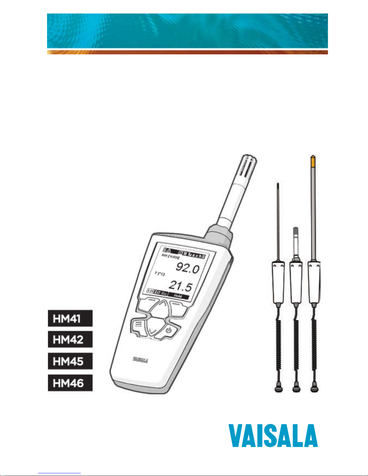
Vaisala HUMICAP® Hand-Held
Humidity and Temperature Meter
HM40 Series
Page 2

PUBLISHED BY
Vaisala Oyj
Street address: Vanha Nurmijärventie 21
FI-01670 Vantaa, Finland
Mailing address: P.O. Box 26
FI-00421 Helsinki, Finland
Phone: +358 9 8949 1
Fax: +358 9 8949 2227
Visit our Internet pages at www.vaisala.com.
© Vaisala 2014
No part of this manual may be reproduced, published
or publicly displayed in any form or by any means,
electronic or mechanical (including photocopying),
nor may its contents be modified, translated, adapted,
sold or disclosed to a third party without prior written
permission of the copyright holder. Translated manuals
and translated portions of multilingual documents are
based on the original English versions. In ambiguous
cases, the English versions are applicable, not the
translations.
The contents of this manual are subject to change
without prior notice.
This manual does not create any legally binding
obligations for Vaisala towards customers or end users.
All legally binding obligations and agreements are
included exclusively in the applicable supply contract
or the General Conditions of Sale and General
Conditions of Service of Vaisala.
Page 3

Page 4

1
Table of Contents
Table of Contents ................................................................................... 1
First Startup ............................................................................................. 4
Initial Settings .............................................................................. 4
Product Overview ................................................................................. 5
HM41 – Front ............................................................................................ 7
HM41 – Back ............................................................................................. 8
HM42 for Tight Spaces ....................................................................... 9
HM45 – Remote Probe with Handle ............................................ 10
HM46 for Mechanically Demanding Applications .................. 12
Batteries ................................................................................................... 13
Charging .................................................................................................. 14
Parameters Explained......................................................................... 15
Measurement Views ............................................................................ 16
Screen Layout and Controls ................................................. 16
Indicators ...................................................................................... 17
Numeric View .............................................................................. 19
Statistics View ........................................................................... 20
Graph View .................................................................................. 21
Hold and Tag .............................................................................. 23
Main Menu ............................................................................................... 25
Tagged Points ............................................................................ 26
Graph Duration .......................................................................... 27
Settings ......................................................................................... 28
Calibration ................................................................................... 28
Help ................................................................................................ 29
Page 5

2
Settings Submenu .............................................................................. 30
Language ..................................................................................... 30
Units ................................................................................................ 31
Time & Date ................................................................................. 31
Pressure ........................................................................................ 33
Reminder ...................................................................................... 34
Backlight ...................................................................................... 35
Battery .......................................................................................... 35
Power off ..................................................................................... 36
Navigation ................................................................................... 36
Rounding ...................................................................................... 36
Factory Settings ....................................................................... 37
How to Measure ................................................................................... 38
Application Examples ....................................................................... 40
Maintenance.......................................................................................... 44
Cleaning ........................................................................................ 44
Changing the Filter .................................................................. 45
Changing the Probe ................................................................ 46
Calibration ..............................................................................................47
Calibrating the HM40 Using HMK15 ................................. 48
Accessories and Parts ....................................................................... 53
Filters ............................................................................................. 54
Chargers and Batteries .......................................................... 55
Belt Clips and Battery Covers ............................................. 55
Technical Data ......................................................................................56
Relative Humidity and Temperature Measurement
Performance ............................................................................... 56
Mechanical ................................................................................... 58
Page 6

3
General .......................................................................................... 59
HM41 Dimensions .................................................................... 60
HM45 Dimensions ..................................................................... 61
HM42 and HM46 Probe Dimensions ................................ 62
Page 7

4
First Startup
1. Check that the probe is securely attached and remove
the yellow transport protection cap from the probe.
2. Open the battery cover and insert two AA-size
batteries.
3. Close the battery cover and turn on the meter by
pressing the Power button. If the meter does not turn
on, check the battery orientation. Replace the
batteries with fresh/recharged ones if needed.
Initial Settings
When you power on the HM40 for the first time (or
after a factory reset of the settings), you must first
select the operation language. The meter will then ask if
you want to change the following settings:
- Units
- Date
- Time
If you answer
Yes
to the question (recommended), the
meter will show the settings screens before showing the
measurement view. Use the arrow and function buttons
to select. For more information, see section Settings
Submenu on page 30.
HM40 will retain the date and time even during
battery changes. The clock will have to be set
again only if the meter is without battery power
for several hours.
Page 8

5
Product Overview
The Vaisala HUMICAP® Hand-Held Humidity and
Temperature Meter HM40 Series comprises four models
designed for various portable measurement
applications. All models in the HM40 series use the
HM40 hand-held indicator with one of four probe
options:
- HM41 – Compact and portable standard option
where a HMP113 probe attaches directly to the
HM40 meter body.
- HM42 – HM40 meter with a spiral cable and handle
connected to an Ø 4mm probe with a length of 235
mm. The structure of the probe is especially suitable
for measurements in tight spaces, such as seams
between wall tiles.
- HM45 – The HM45 uses the same HMP113 probe as
HM41, but with a probe handle connected to the
HM40 meter with a spiral cable, providing additional
reach.
- HM46 – HM40 meter with a spiral cable and handle
connected to a 320 mm robust stainless steel probe
designed for mechanically demanding applications
such as dirty processes and relatively high
temperatures (temporarily up to 180 °C).
For more information on using the probes, see
Application Examples on page 40.
For probe dimensions and technical data, see pages 56
and 60.
Page 9

6
Main features of the HM40 series:
- Compact and robust housing.
- Measures a wide range of parameters: RH, Td, Tw, a,
x, h, T. See section Parameters Explained on page
15.
- Large graphical display.
- Graphs for selected humidity parameter and
temperature.
- Can be user calibrated (using the HMK15 humidity
calibrator, for example).
- Powered by standard AA size batteries (2×).
- Indicator operation temperature range -10°C ...
+60°C. Probe operation temperature ranges
-40 °C … +180°C, depending on probe model.
- Short (HM41/HM45) or long (HM42/HM46) soft
case, depending on probe length.
- Belt clip.
Optional accessories:
- Different filters for increased protection against
contaminants.
- USB-powered portable charger for AA-size NiMH
rechargeables.
For more information and order codes of the
accessories, see section Accessories and Parts
on page 53.
Page 10

7
HM41 – Front
HMP113 probe
Filter and sensor
Probe holder
Display
Right function
Left function
Down
Up
Power
Menu
Page 11

8
HM41 – Back
Belt clip
Battery
cover
Batteries
2 x AA
Page 12

9
HM42 for Tight Spaces
Page 13

10
HM45 – Remote Probe with
Handle
HM40
handle
HMP113 probe
Probe
holder
Cable connector
Orientation mark
Page 14

11
You can connect the HM45 handle to the belt clip for
single handed use. Simply push the belt clip into the slot
in the handle.
When the handle is connected to the meter in this way,
you can lay down the meter on top of the handle.
Page 15

12
HM46 for Mechanically
Demanding Applications
Page 16

13
Batteries
The HM40 is powered by
two AA-size batteries
. You
can use the following battery types:
- Alkaline (IEC-LR6)
- Lithium (IEC-FR6)
- NiMH (IEC-HR6)
Do not mix batteries of different types. Both
batteries must be of the same type.
Observe the storage and operation instructions of
the battery manufacturer.
Alkaline batteries are the standard choice in nonrechargeable batteries. They are a good match for the
power requirements of the HM40.
Lithium batteries are a good choice if you need the
longest battery life or best capacity in low
temperatures. Lithium batteries are not rechargeable.
Do not confuse them with lithium-ion batteries, which
cannot be used in the HM40.
NiMH batteries are rechargeable, and available from
Vaisala as an option. For order codes, see section
Accessories and Parts on page 53. Instructions for using
the optional USB charger are provided in section
Charging on page 14.
Page 17

14
Charging
The optional USB charger provides a convenient way to
charge two NiMH batteries from any powered USB port
(for example, from a laptop computer).
1. Place the rechargeable batteries in the charger and
plug it into a USB port. The blue LED on top of the
charger starts to blink.
2. When the LED stops blinking and stays on, the
batteries are charged. The charging time is several
hours for two fully discharged NiMH batteries.
If you are not using a Vaisala-supplied charger and
rechargeable batteries, read and follow the
manufacturer’s own charging instructions.
Do not attempt to charge non-rechargeable
(alkaline or lithium) batteries! Doing so leads to a
risk of battery leakage, equipment damage, and
risk of explosion and/or fire.
Page 18

15
Parameters Explained
The table below describes the parameters measured by
the HM40. All of the parameters are measured or
calculated when the meter is on, independent of what is
currently displayed. The parameters are also described
in the indicator’s Help menu (see page 29).
Parameter Symbol Unit(s) Description
Relative
humidity
RH
%
Ratio of the partial pressure of
water vapor in the air to the
saturation vapor pressure of air
at the current temperature.
Dewpoint Td °C
°F
Temperature at which the water
vapor in the air will condense into
water at the current pressure.
When the dew point is below 0
°C, the meter outputs frost point
instead of dew point.
Wet bulb
temperature
Tw °C
°F
The minimum temperature that
can be reached by evaporative
cooling in the current conditions.
Absolute
humidity
a g/m
3
gr/ft3
Quantity of water in a cubic
meter (or cubic foot) of air.
Mixing ratio
x
g/kg
gr/lb
Ratio of water vapor mass per
kilogram (or pound) of dry air.
Enthalpy h kJ/kg
btu/lb
Sum of the internal energy of a
thermodynamic system.
Temperature T °C
°F
Temperature in Celsius or
Fahrenheit scale.
Page 19

16
Measurement Views
Screen Layout and Controls
Pressing the right function button holds the screen
and tags the current measurement point.
See Hold and Tag on page 23.
Battery
indicator
Alert indicator
Change quantity
Enter menu
Long press:
tag point
Short press:
tag point and
hold screen
Measurement
display area
Long press: power on/off
Short press: activate backlight
Current quantity
Change
view
Current
view
Page 20

17
Indicators
Battery charge indicator
Fresh batteries will always show three
bars.
When the indicator shows two bars, the
voltage of the batteries has started to
drop. When there is a single (blinking)
bar left, you should replace the batteries.
The meter will turn off automatically
when the battery voltage drops too low.
Alert indicator
This indicator is shown next to the
battery charge indicator if there is a
measurement problem. The most likely
causes are low battery and probe
problems, for example:
- Battery voltage too low to power the
probe. The measured values may
show asterisks "*" instead of
numbers.
- Probe has been disconnected
- Probe has been damaged
- Probe is incompatible
- Probe is wet (probe recovers
automatically when it dries). The
measured values may show asterisks
"*" instead of numbers.
Page 21

18
Parameter indicator
The selected parameter is highlighted by
a light frame. The symbol on the right
stands for all parameters.
For the list of parameters, see section
Parameters Explained on page 15.
Calibration reminder indicator
This indicator appears when you have set
up a calibration reminder and the
calibration is due. The indicator is shown
until you calibrate the probe.
For instructions on setting up a
calibration reminder, see section
Reminder on page 34.
Page 22

19
Numeric View
The
Numeric view
shows the
current values of the selected
humidity parameter and
temperature.
In the all parameters view, the font
is smaller to fit all values on screen.
Page 23

20
Statistics View
The
Statistics view
shows the
current value of the selected
parameter, as well as the
maximum, average, and minimum
value since the measurement was
started. There is also a counter that
shows how long the measurement
has been running.
The icons are:
Maximum
Average
Minimum
Measurement time
The counter for measurement time
is not shown in the all parameters
view.
Page 24

21
Graph View
The
Graph view
shows a
continuously updating graph of the
selected parameter and
temperature.
The graph limits and spacing adjust
dynamically to show the full range
of measurements.
HM40 has no permanent memory for graph data:
when the meter is turned off, the graphs are
cleared. Only tagged points are stored in
permanent memory. To avoid losing graph data
while working, set a suitable delay for the
automatic power off (see Power off on page 36)
or disable it.
Page 25

22
You can change the timescale of
the graph in the
Main menu
.
By default, the graph will
automatically change the timescale
to fit the measured data. If you
select a short timescale, only the
most recent data will be visible.
The graph view is not available in
the all parameters view. Select a
single parameter to show the
graph.
Page 26

23
Hold and Tag
If you press the right function button (
Hold
button) in a
measurement view, two things happen:
- The measurement view freezes until you press the
Release
button.
- The latest measurement point is tagged (marked and
stored in permanent memory). See section Tagged
Points on page 26.
Tagged points are shown in the graph view as small dots
below the graphs.
Page 27

24
You can view the measurement
values at the tagged points in the
menu. You can also view and delete
tagged points from memory in the
menu options. See Tagged Points
on page 26.
When the screen is held, the top of
the display displays the current
date and time. This is useful when
you want to record the current data
(take a photograph or write it
down).
If time has not been set, the top of
the screen will simply read “HOLD”.
When the view is held, you can reset all
measurement data by pressing the
Reset
button. This will clear all graphs and tagged
points.
If you keep pressing the right function button
(long press), the meter will tag the point without
freezing the screen.
Page 28

25
Main Menu
You can open the menu from the measurement view at
any time by pressing the menu button.
If you are already in the menu, pressing the menu
button returns you to the measurement view. If you are
in a submenu, the menu button returns you to the
previous menu level.
Use the arrow buttons to move
up and down in the menu, and
function buttons to operate the
menu options. Typical functions in
the menus are:
-
View
and
Enter
open the
selected menu option or
submenu.
-
Change
and
Set
change the
value of the selected option.
-
Back
returns to the previous
menu view.
-
Exit
closes the menu and
returns to the measurement
view.
Page 29

26
Some menu screens have more content than can
be visible at one time. This is indicated by a scroll
bar that appears on the right side of the screen. Use
the arrow buttons to scroll up and down.
Tagged Points
Select Tagged points in the main
menu to see the list of stored points
and values.
Time and temperature value are
always shown for each tagged point.
The humidity parameter that is shown
is the same as you have selected in the
measurement view. If all parameters
view has been selected, RH is shown
instead.
Page 30

27
The data stored for each tagged point
includes:
- Time when the point was tagged.
- Serial number of the probe that
was used (useful for identifying
the point)
- Measured value of each
parameter.
Press the
Delete
button to delete the
point that is currently shown. To delete
all points in memory, hold down the
Delete button.
HM40 can store up to 40 tagged points. If a new
tagged point is stored when the memory is full, the
oldest tagged point is silently deleted to make
room for the new point.
Graph Duration
In the
Graph duration
screen, you
can select the timescale of the
Graph view. The shortest selectable
timescale is 1.5 minutes, the longest
32 hours.
You can also select
Autoscale
,
which means that the timescale will
automatically adjust to show all of
the measurement data in memory,
up to the maximum of 32 h.
Page 31

28
Settings
Opens the
Settings
menu. The
menu options are described in
section Settings Submenu on
page 30.
Calibration
In the Calibration submenu, you
can perform an adjustment
procedure that corrects the
humidity and temperature
measurement of the meter.
For more information and the
adjustment procedure, see
section Calibration on page 47.
Page 32

29
Help
Opens a menu with help topics
on measurement, calibration, and
the measured parameters.
The help menu also includes a
device information screen where
you can view technical
information about your indicator
and probe.
Page 33

30
Settings Submenu
Language
In the
Language
screen, you can
change the display language of the
meter. The choices are:
- English (en)
- German (de)
- French (fr)
- Finnish (fi)
- Spanish (es)
- Swedish (sv)
- Chinese (zh)
- Russian (ru)
- Japanese (jp)
- Portuguese (pt)
Page 34

31
Units
The
Units
setting determines the
measurement system that is used
for the parameters: metric or nonmetric.
- Metric
- Non-metric
The
Pressure unit
is set
separately:
- hPa
- bar
- atm
- PSI
Time & Date
In the
Time & Date
menu, you can
set the current date and time, and
their presentation formats. Both
date and time have their own
pre-set formatting options.
Page 35

32
In the
Date setup
screen, you can
set the current date:
-
Arrow buttons
change the
selected value
-
Left function
button selects
the next value (year, month,
or day).
-
OK
button stores the date
and returns to the Settings
menu.
After setting the date, set the
desired date format using the
Formatting
option in the Time &
Date menu.
In the
Time setup
screen, you can
set the current time:
-
Arrow buttons
change the
selected value.
-
Left function
button selects
the next value (hours,
minutes, or seconds).
-
OK
button stores the time
and returns to the Settings
menu.
After setting the time, select 24h
or 12h clock using the
Formatting
option in the Time & Date menu.
Page 36

33
Pressure
In the
Pressure setup
screen, you
can set the current ambient
pressure. The pressure information
is used when calculating certain
humidity parameters, such as
mixing ratio (symbol x).
If the ambient pressure differs
significantly from the default setting
of 1.0132 bar (due to high altitude,
for example), set the correct
pressure value so that the HM40
meter can calculate the
measurement correctly.
Page 37

34
Reminder
Use the
Reminder
option to set a
reminder for calibrating the probe.
You can choose a preferred
calibration interval of 3, 6, 12, or 24
months. Calibrating the probe
resets the calibration interval. To
remove the reminder from use,
select
Disabled
.
Note that you must set the correct
date in the indicator for the
calibration reminder to appear as
intended.
The calibration reminder appears
one month before the preferred
calibration date is due.
To continue displaying the
reminder for this interval, select
Snooze
. The reminder will appear
again at each power-on.
To hide the reminder, select
Close
.
If you do not calibrate within a
month, the reminder will appear
again.
Calibrating any parameter in the probe resets
the calibration interval. This means that if you
leave one parameter uncalibrated in a
calibration session, the reminder will not
appear separately for that parameter.
Page 38

35
Backlight
Always on
: Screen is always lit.
This option will shorten the
battery life significantly.
Always off
: Screen is always
unlit. This option provides the
best battery life.
Delay (30s)
: Backlight will
automatically turn on when the
user presses any button. The
backlight will turn off after
30 seconds of inactivity.
Dimmed
: Screen is always lit
with a dim backlight.
Battery
Use the
Battery
setting to tell the meter what kind of
batteries are installed. This will help to scale the battery
indicator correctly. The options are:
- Alkaline
- Rechargeable
Page 39

36
Power off
The
Power off
setting defines how long the device can
remain inactive before powering off automatically. The
time limit options are 10, 30, and 60 minutes. Select
Never
to disable automatic power off.
HM40 has no permanent memory for graph data:
when the meter is turned off, the graphs are
cleared. Only tagged points are stored in
permanent memory. To avoid losing graph data
while working, set a suitable delay for the
automatic power off or disable it.
Navigation
Navigation setting affects the behavior of arrow buttons
in the measurement view:
-
Normal
: Up arrow moves parameter selector left,
down arrow moves it right
-
Inverted
: Reverses the direction
Rounding
Rounding setting affects the number of decimal places
that are used to show the measurements:
-
On
: Measured values are rounded to
one
decimal
place.
-
Off
: Measured values are shown with
two
decimal
places.
Page 40

37
Factory Settings
The
Factory settings
option
restores all settings to their default
values. Probe calibration is not
affected.
Page 41

38
How to Measure
Remove the Transport Protection Cap
Remove the yellow transport protection cap from the
probe when taking the meter into use.
Measure in a Stable Environment
If the measurement conditions are changing, you cannot
get a reliable measurement result. Do not measure near
heat sources, air conditioning, open doors, or windows.
For best results, leave the meter on in the
measurement area and come back to check it
la ter.
Avoid Temperature Differences
Temperature differences are a typical cause of error in
humidity measurement and calibration. You must let the
meter stabilize long enough: temperature differences
level out very slowly.
Switch to the Graph view and
wait until the graphs level out,
indicating that the
measurement is now stable.
Page 42

39
Avoid Condensation and Rain
If the humidity sensor element becomes wet, the meter
cannot measure until the sensor is dry again. Avoid rain
and conditions where condensation can form on the
sensor.
Do not replace the transport protection cap if the probe
or the cap is wet, since it will prevent the probe from
drying.
Do not touch the sensor or blow on it to dry it
out.
Calibrate the Meter Regularly
It is recommended that you calibrate the probe
once a
year
, or if you have any reason to believe it is no longer
within its accuracy specification. See section Calibration
on page 47.
You can set a reminder for calibration at preferred
calibration intervals (3, 6, 12 or 24 months). See section
Reminder on page 34.
Page 43

40
Application Examples
HM41
HM41 uses a fixed HMP113 probe, providing a compact
solution that is ideal for spot checks in open spaces.
The optional membrane filter for the HMP113 probe
increases protection against contaminants.
When measuring with
HM41, always hold the
meter at a sufficient
distance to avoid
affecting the results
with moisture from
your breath.
HM45
HM45 uses the same HMP113 probe as HM41. In HM45,
the probe is attached to a handle that is connected to
the HM40 indicator with a spiral cable, providing
additional reach.
Page 44

41
HM42
HM42 has a small, Ø 4 mm probe head with a length of
235 mm. The thin structure of the probe makes it
suitable for measurements in tight places such as joint
spaces between tiles and beneath flooring.
Typical applications include mapping the affected area
in water damage restoration, measuring moisture in
insulation materials, and measuring the equilibrium
humidity of, for example, timber.
Use a suitable tool such as a screw driver to create a space
for the probe before inserting it.
To avoid bending or damaging the probe, never force it
through structures.
Page 45

42
When measuring, for
example, from a wall so that
the probe is placed in a
horizontal position, make
sure the probe does not
bend: do not leave the
probe unsupported.
Always insert the probe at
least 4 cm inside the
structure from which you
are taking measurements.
Never leave the meter and
the handle hanging down
freely from the probe.
Page 46

43
HM46
HM46 uses a 32 cm stainless steel probe that is
optimized for mechanically demanding applications that
require a robust probe structure, for example
measurements in relatively high temperatures (up to
+100 °C, temporarily even +180 °C) or in dirty
processes.
In addition to water damage mapping applications,
common uses for the HM46 include plant maintenance
and the installation and inspection of air conditioning
systems, production and storage areas, and production
processes.
Page 47

44
Maintenance
Cleaning
The HM40 can be cleaned by wiping it with a moist
cloth.
If the filter becomes contaminated, it is very likely to
affect the humidity measurement since residue on the
filter will retain some moisture. Dirty filters should be
replaced.
Do not use solvents to clean the HM40. Do not spray
anything directly on the HM40, since that may deposit
impurities on the sensor.
Do not immerse the HM40 in liquid to clean it.
Do not attempt to clean the sensor element that is
located inside the filter. Any touching (or blowing
with pressurized air) may damage it. If the
measurement accuracy cannot be restored by
calibration and adjustment, it is time to replace the
probe.
Page 48

45
Changing the Filter
For information on filter options, see Filters on page 54.
1. Turn the filter counter-
clockwise to open it.
2. Turn the filter until it can be
removed.
3. Pull the filter out straight.
Do not touch the sensors
with the filter.
4. Install the new filter and
tighten it.
Page 49

46
Changing the Probe
Changing the probe is tool-free and is done in the same
way for the HM41 probe attached to the meter body
and when using one of the probes with a handle.
1. Press the power button to
turn off the meter.
2. Turn the probe holder (the
grey nut at the base of the
probe) counter-clockwise
to loosen the probe.
3. Pull the probe holder and
probe together away from
the connector.
4. If the new probe does not
have a probe holder,
remove it from the old
probe by pulling it over the
filter and place it on the
new probe.
5. Push the pins of the new
probe in the holes of the
connector. Tighten the
probe holder.
6. Press the power button to
turn on the meter.
If the alert indicator comes on after starting the
meter, check the connection and verify that the
probe has been ordered as a spare part for the
HM40.
Page 50

47
Calibration
The humidity measurement accuracy of the probe should
be checked
once a year
. You can do this yourself using a
humidity reference (for example, the Vaisala Humidity
Calibrator HMK15), or send the probe to a Vaisala Service
Center for calibration
For instructions on setting a calibration reminder message
(3-24 month interval), see Reminder on page 34.
If the calibration shows that the measurement accuracy is
no longer within specification, the probe must be adjusted.
If accuracy cannot be restored with adjustment, the probe
must be replaced. All probes that are ordered from Vaisala
are delivered calibrated. See section Accessories and Parts
on page 53.
If you think the meter is not measuring humidity
or temperature correctly, calibration and
adjustment is not the first thing to do. Try the
following first:
- Make sure nothing is interfering with the
measurement: heat sources, temperature
differences, or condensation.
- Check that there is no moisture on the
probe. If the sensor has become wet, you
must allow it to dry before you can measure.
- Always wait for the measurement to
stabilize.
For an introduction to calibration, order or
download the free calibration book:
www.vaisala.com/calibrationbook
Page 51

48
Calibrating the HM40 Using HMK15
The HMK15 Humidity calibrator allows you to produce
known humidity environments using saturated salt
solutions.
Performing a good calibration takes some time
and preparation. Read the HMK15 User’s Guide
before performing your first calibration with the
HMK15.
1. Press the Menu button and select
the
Calibration
submenu.
2. Select the parameter to be
calibrated at menu item
[1]
Quantity
. You can calibrate
Temperature (T) or Relative
Humidity (RH) measurement. All
other humidity parameters are
calculated from RH and T, so they
will also be adjusted.
Page 52

49
3. Select the number of
calibration points at menu item
[2] Points
. You can perform a 1-
point or 2-point calibration.
For a 2-point calibration, you
need two reference
environments. For example,
LiCl and NaCl salt chambers
provide 11% and 75% relative
humidity references.
Note that when performing a 2point RH calibration, the first point
requires a < 50% RH humidity
reference, and the second point
must be > 50% RH.
The difference between the two
references must be at least 30%
RH.
4. Remove the filter from the probe
and place the probe in the first
reference environment (first
calibration point).
Take care not to damage the
sensors. Wait 20 – 40 minutes for
the reading to stabilize.
Page 53

50
5. Select menu item
[3] Point 1
and
press the Set button. The meter
now shows the currently
measured value of the selected
parameter. Set the reference value
using the arrow buttons and press
the OK button.
The correction to the
measurement at point 1 is now
shown in the text for menu item
[3]. If you are only doing a 1-point
calibration, skip to
step 8.
6. Place the probe in the second
reference environment (second
calibration point). Wait 20 – 40
minutes for the reading to
stabilize.
Page 54

51
7. Select menu item
[4] Point 2
and
press the
Set
button. The meter
now shows the currently
measured value of the selected
parameter. Set the reference value
using the arrow buttons and press
the
OK
button.
The correction to the
measurement at point 2 is now
shown in the text for the menu
item [4].
8. Select menu item
[5] Note
to edit
the calibration info text that is
stored in the probe. Edit the text
using the select button and arrow
keys. When done, select the OK
character in the bottom right
corner to save the changed text.
To exit without saving, press the
Cancel
button.
Page 55

52
9. Select menu item
[6] Apply
to
save the calibration in the probe.
Check the applied corrections in
the confirmation screen and press
the Apply button.
To exit without applying the
correction, press the
Cancel
button.
Page 56

53
Accessories and Parts
Order code
HM40 indicator, no probe
HM40INDI
Belt clip (3 pcs)
227710SP
Battery cover (3 pcs)
225688SP
NiMH rechargeable batteries (4 pcs)
229247SP
External battery recharger with USB
connection and 2 batteries
229249SP
Case for short HM40 probes
235849SP
Case for long HM40 probes
DRW242351SP
HM41 & HM45 probes
HMP113 probe for HM40
HMP113 (conf. V00B2C1A0)
Plastic nut for HMP113 attachment
DRW238590SP
Plastic grid filter for HMP113 probe
DRW236214SP
Plastic grid with membrane filter
for HMP113 probe
230727SP
HM40 handle and cable (HM45 only)
HM40HANDLE
HM42 probe
Probe for HM42, diameter 4 mm
HM42PROBE
Steel grid filter for sensor protection
19867HM
Membrane tube set (5 pcs) for filter
19858HM
Rubber sleeve set (10 pcs)
19809HM
Calibration adapter for HM42PROBE
HM37067
HM46 probe
Probe for HM46, diameter 12 mm
HM46PROBE
Sintered filter
0195
Membrane filter, up to 80 °C
10159HM
Plastic grid filter, up to 80 °C
6221
Disposable sleeve (50 pcs)
1558
Probe holder
HM36915
When ordering an HMP113 probe for HM41 and
HM45, use the HMP113 configuration code
V00B2C1A0 to get the compatible probe.
Page 57

54
Filters
HM41 & HM45 (HMP113 probe)
Plastic grid filter
The standard choice. It provides the fastest
response time, as air can flow freely around the
sensors.
Plastic grid with
membrane filter
Has a membrane under the plastic grid (0.2 µm
pore size) for additional protection against
contaminants. It slows down the response time
of the probe.
HM42
Steel grid filter with
membrane tube
The standard choice. The membrane should be
changed periodically and when it is getting
dirty.
HM46
Sintered filter
The standard choice. It has the same
temperature tolerance as the probe itself.
Plastic grid filter
Provides a faster response time than the
sintered filter but it has a more limited
temperature tolerance. This filter is only
recommended for non-demanding applications.
Membrane filter
Provides a faster response time than the
sintered filter but it has a more limited
temperature tolerance. The membrane under
the plastic grid provides additional protection
against contaminants compared to using only
the plastic grid filter.
For instructions on replacing a filter, see section
Changing the Filter on page 45.
Page 58

55
Chargers and Batteries
You can order an external battery recharger with USB
connection and compatible NiMH rechargeable batteries
from Vaisala. For more information, see the following
sections of this manual:
- Batteries on page 13
- Charging on page 14
Belt Clips and Battery Covers
If you need a new belt clip or battery compartment
cover, you can order replacements from Vaisala.
Page 59

56
Technical Data
Relative Humidity and Temperature
Measurement Performance
Relative Humidity
Measurement range
0 ... 100 %RH
Accuracy (including non-linearity,
hysteresis, and repeatability)
HM41
at 0 … +40 °C
±1.5 %RH (0 ... 90 %RH)
±2.5 %RH (90 ... 100 %RH)
at -10 … 0 °C and +40 … +60 °C
±3.0 %RH (0 ... 90 %RH)
±4.0 %RH (90 ... 100 %RH)
HM42
at 0 … +40 °C
±1.5 %RH (0 ... 90 %RH)
±2.5 %RH (90 ... 100 %RH)
at -40 … -0 °C and +40 … +80 °C
±3.0 %RH (0 ... 90 %RH)
±4.0 %RH (90 ...100 %RH)
at +80 …+100 °C
±4.0 %RH*
*)
Not recommended for T
d
> 85 °C.
HM45
at 0 … +40 °C
±1.5 %RH (0 ... 90 %RH)
±2.5 %RH (90 ... 100 %RH)
at -40 … 0 °C and +40 … +60 °C
±3.0 %RH (0 ... 90 %RH)
±4.0 %RH (90 ... 100 %RH)
HM46
at 0 … +40 °C
±1.5 %RH (0 ... 90 %RH)
±2.5 %RH (90 ... 100 %RH)
at -40 … -0 °C and +40 … +80 °C
±3.0 %RH (0 ... 90 %RH)
±4.0 %RH (90 ... 100 %RH)
at +80 …+100 °C
±4.0 %RH*
*)
Not recommended for T
d
> 85 °C.
Factory calibration uncertainty
at +20 °C (+68 °F)
±1.5 %RH
Page 60

57
Humidity measurement response time
HM41, HM45
(90%) with plastic grid filter
17 s
HM42
(90 %) with membrane filter and
steel grid
26 s
HM46
(90 %) with brass sintered filter
40 s
Stability
±2 %RH over 2 years
Humidity sensor
HM41, HM45, HM46
HUMICAP® 180R
HM42
HUMICAP® 100R-Mini
Temperature
Measurement range
HM41
-10 ... +60 °C (+14 ...+140 °F)
HM42
-40 ... +100 °C (-40 ... +212 °F)
HM45
-40 ... +60 °C (-40 ... +140 °F)
HM46
-40 ... +100 °C (-40 ... +212 °F),
short-term up to +180 °C
(+356 °F)
Accuracy over temperature range
at 0 ... +40 °C (+32 ... +104°F)
±0.2 °C (0.36 °F)
at -40 ... 0 °C and +40 ... +100 °C
(-40 ... +32 °F and +104 ... +212 °F)
±0.4 °C (0.72 °F)
Temperature Sensor
HM41, HM45, HM46
Pt1000 RTD Class F0.1
IEC 60751
HM42
Pt1000 RTD Class F0.3
IEC 60751
Page 61

58
Mechanical
Weight (with alkaline batteries)
HM41
230 g
HM42
370 g
HM45
330 g
HM46
490 g
Materials
Meter body
PC/ABS blend,
acrylic display lens
Probe holder
PC/AB S blend (grey)
Probe handle
PC/ABS blend (white),
PC/ABS blend (gray, HM45)
or PBT (gray, H M42 /46
HMP113 probe or probe
measurement head
PC/ABS blend (white, HM41/45),
or stainless steel (HM42/46)
Filter
HM41, HM45
HM42
HM46
PC (glass reinforced)
Stainless steel, PTFE membrane
Sintered brass
Housing classification
IP54
HM42 and HM46 probes
IP40
Page 62

59
General
Power-up time
<3 s
Batteries
2 × AA sized, 1.5 V
Calculated parameters
Td, Tw, a, x, h
Menu languages
English, Chinese (simplified), Finnish,
French, German, Japanese,
Portuguese, Russian,
Spanish, Swedish
Display
LCD (140 x 160 pixels)
Operation time (typical)
typical 100 hours
(without backlight)
Operation temperature range
Indicator
Probe handle
Probe head
-10 ... +60 °C (+14 ... +140 °F)
-40 ... +60 °C (-40 ... +140 °F)
(see specifications for each probe type,
ranges -40 …+180 °C (-40 … 356 °F))
Storage temperature range
-30 ... +70 °C (-22 ... +158 °F)
Electromagnetic compatibility
(EMC)
EU directive EN61326-1 for portable
equipment
Page 63

60
HM41 Dimensions
The dimensions are given in millimeters (mm).
72
238
44
12
155
83
30
Page 64

61
HM45 Dimensions
The dimensions are given in millimeters (mm).
Page 65

62
HM42 and HM46 Probe Dimensions
The dimensions are given in millimeters (mm).
Page 66

Page 67

*M211088EN*
Download manuals at:
www.vaisala.com/manuals
Technical support by e
-mail:
helpdesk@vaisala.com
Warranty information:
www.vaisala.com/warranty
Vaisala Service Centers:
www.vaisala.com/servicecenters
Purchase instruments and
spare parts online at
store.vaisala.com
 Loading...