


UVX Radiometer
Table of contents
 Loading...
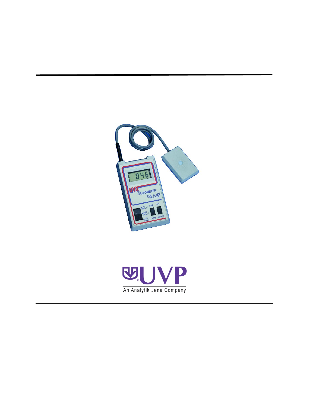
UVX Radiometer
Instruction Guide
UVP, LLC Ultra-Violet Products Ltd.
2066 W. 11th Street Unit 1, Trinity Hall Farm Estate
Upland, CA 91786 Nuffield Road, Cambridge CB4 1TG UK
Phone: (800) 452-6788 Phone: +44(0)1223-420022
Fax: (909) 946-3597 Fax: +44(0)1223-420561
Web Site: www.uvp.com
81-0064-01 Rev M

UVX Radiometer 2
Table of Contents
General Instructions ...................................................................................................................................... 5
Introduction ................................................................................................................................................ 5
Features..................................................................................................................................................... 5
Specifications ............................................................................................................................................ 6
Operating Procedures ............................................................................................................................... 6
Radiometer Details ........................................................................................................................................ 9
Circuit Description ..................................................................................................................................... 9
Radiometer Circuit Calibration .................................................................................................................. 9
Radiometer Maintenance ........................................................................................................................ 10
Sensor Details ............................................................................................................................................. 15
Sensor Characteristics ............................................................................................................................ 15
Calibration Information ............................................................................................................................ 15
Sensor Maintenance ................................................................................................................................ 19
General Precautions ................................................................................................................................ 19
Application Techniques ............................................................................................................................... 22
Definition of Radiant Incidence ................................................................................................................ 22
Wavelength Considerations..................................................................................................................... 22
Cosine Response .................................................................................................................................... 25
Summary ................................................................................................................................................. 25
Safety Precautions ...................................................................................................................................... 26
Component List, Replacement Parts, and Options ..................................................................................... 29
Component List ....................................................................................................................................... 29
Replacement Parts .................................................................................................................................. 30
Options .................................................................................................................................................... 30
Warranty ...................................................................................................................................................... 31

UVX Radiometer 3
List of Figures
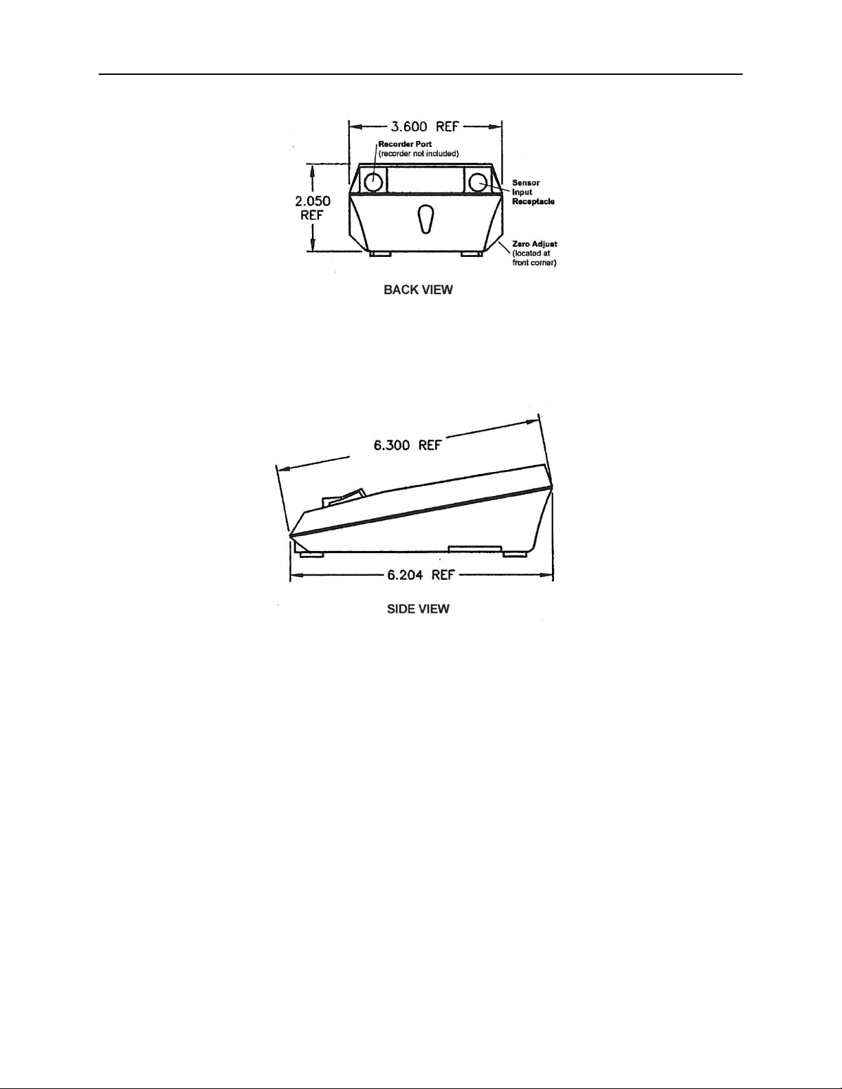
Figure 1: Rear and Side Views of Radiometer.............................................................................................. 4
Figure 2: Radiometer Functional Block Diagram ........................................................................................ 13
Figure 3: Calibration Current Source .......................................................................................................... 14
Figure 4: LCD Display Pin-outs ................................................................................................................... 14
Figure 5: UVX-25 Sensor S olari za ti on Curve ............................................................................................. 16
Figure 6: Typical UVX-25 Sensor Spectral Response ................................................................................ 16
Figure 7: Typical UVX-31 Sensor Spectral Response ................................................................................ 17
Figure 8: Typical UVX-36 Sensor Spectral Response ................................................................................ 17
Figure 9: Typical Sensor Respons e Vers us Inci de nc e Ang le ..................................................................... 18
Figure 10: Schematic of UVX Series Sensor .............................................................................................. 20
Figure 1: Measurement of Irradiance .......................................................................................................... 20
Figure 12: Typical Output From Low Pressure Mercury Lamp ................................................................... 21
Figure 13: Hypothetical Light Source Having an Output at 270nm Wavelength ........................................ 24
Figure 14: Response of Three Sensors Calibrated to Yield the Same Output at 254nm Wavelength ....... 24
Figure 15: Continuous Emitter, 285nm Phosphor Coated UV Lamp .......................................................... 25
Figure 16: Example, Illustrating Why Sensor Field of View is Important When Measuring Irradiance ....... 27
Figure 17: Projected Area of Sensor ........................................................................................................... 27
Figure 18: Cosine Response of Typical UVX Sensor (Polar Plot) .............................................................. 28
UVX Radiometer 4
Figure 1: Rear and Side Views of Radiometer

UVX Radiometer 5
General Instructions
Introduction
Your new UVX Digital Radiometer from UVP allows measurement of UV intensities quickly and easily.
The digital readout is in radiometric units with a broad dynamic range from 0.1 µW/cm
accuracy and precision traceable to the National Institute of Standards and Technology (NIST). The
sensors are cosine corrected for measuring UV radiation at 254, 310 and 365nm. Each sensor is also
pre-calibrated and quickly interchangeable with any other sensor without affecting the overall system
accuracy.
Designed for simplicity and durability, the UVX is built with the latest in solid state electronics, has a
rugged housing, over-ranging, and low battery indicato r s . By using circuitry that is powered by a single 9V
transistor battery, UVX is completely portable. It can be used in a wide variety of research and industrial
applications. Some typical applications using UV light sources are: genetic experiments, photochemical
reactions, sterilization procedures, optical lab measurements, experimental biology, dermatology
research, NDT techniques and graphics procedures.
The UVX Series Sensor supplied with this unit, as well as all other UVX Series Sensors, is designed and
calibrated for measurement of radiant incidences from line type and phosphor coated mercury arc
sources. There are several parameters including calibration, spectral response and sensor field of view
which users should understand to ensure accurate measurements. Refer to the Applications Techniques
section of this manual, which addresses these subjects.
Features
The following is a list of features provided by the UVX Radiometer and Sensor:
• Three sensitivity ranges covering the span from 200 µW/cm
• 3-1/2 digit liquid crystal display readout
• Sensitivity down to 0.1 µW/cm
2
• Outstanding ruggedness and reliability
• Negligible sens it i v it y to inf r a re d
• Linearity of
± 1% over the total range, ± one digit
• Readout and sensor are stored in their own storage and carrying case with room for
one additional sensor
• Light weight
• Powered by a single 9V transistor battery
• Long battery life (more than 120 hours of continuous operation with a single alkaline
battery)
• Automatic low voltage battery indication (”LOBAT” or “:” displayed on the LCD screen)
• Not sensitive to capacitive or AC pick up
• Fully interchangeable sensors for full UV band coverage
• Automatic circuit that tests the display each time the unit is turned on
• Read/Hold switch that allows holding any reading indefinitely
• Automatic reverse battery connection protection circuit
• Calibration of sensors is traceable to NIST through a standard lamp and proven
laboratory techniques
• Independent calibration of all sensors and digital Radiometers allowing complete
interchangeability without reference to individual calibration factors
• Remote sensor of small size permitting measurements to be taken in constricted
areas
• Three foot long electrically shielded connecting cable
1/4-20 UNC-2B threaded mounting hole compatible with standard tripod mount screws
•
2
to 20 mW/cm2
2
to 20 mW/cm2 with

UVX Radiometer 6
• Excellent cosine response with typical curve supplied in the manual
• A filter system which significantly reduces shortwave solarization phenomenon
• Internal temperature correction retains the accuracy of the sensors at both high and
low temperatures
• Externally accessible zero adjus t
• Connector port for an external chart recorder (recorder not included)
Optional Accessories
• A 10-to-1 attenuator allowing readings to be made up to 200mW/cm
2
.
Specifications
Radiometer
Conversion Rate: 2.8 readings/sec
Display: 3-1/2 digit LCG
Accuracy: ±2.5%
Linearity: ±0.2%
Resolution: 1 part in 1999
Sensitivity Ranges: 0 to 199.9 µW/cm
0 to 1999 µW/cm
0 to 19.99 mW/cm
0 to 199.9 mW/cm
Temperature Coefficient: ±0.025%/°C ± 1 digit, 0 to 50°C
Zero Drift: ±0.02 uW/cm
2
2
2
2
w/10:1 Attenuator
2
/°C nominal 0 to 50°C
Power: 9V transistor battery
Battery Life (Alkaline): 120 Hrs (without recorder output option)
Sensor
Spectral Response: See Figures 6, 7, 8
Accuracy: ±5% (includes NIST standard)
Linearity: ±1.0%
Cosine Response: See Figure 9
Temperature Coefficient: ±0.04%/°C nominal, 0 to 40°C
Zero Drift: ±0.35 uW/cm
2
/°C nominal 0 to 50°C
Operating Environment
Temperature: 0 to 50°C
Humidity: 5% to 90% RH
Operating Procedures
The UVX Radiometer provides versatilit y and simplicity of operation. The num ber of front panel controls
has been held to a minimum. Range changes are made by means of a three position range switch.
Access to the zero adjust trimpot is available through the hole in the left hand side of the case. This
simplifies the operation of the instrument and also minimizes operator error.
The procedure that follows will help in understanding the operation of this instrument.
• Turn the Radiometer over and open the battery cover to determine if the battery has been
installed. If it is has not, s n ap the b at tery clip in place, insert the battery into the holder, then clos e
the battery cover.
• Plug the UVX sensor into the mating connector at the left rear of the UVX Radiometer. This
receptacle is identified in Figure 1.
Note: The connector goes t hrough two "snap " positions before it is fully inserte d. Failure to ins ert the
connector all the way will result in erroneous readings.

UVX Radiometer 7
• Place the three position range s witch in the 20 mW/cm 2 position. Place the READ/HOLD switch
in the READ position.
• Turn the unit on by placing the OFF-ON/TEST switch in the ON/TEST position.
Note: For the first second of operation, the entire display will be turned on demonstrating that all
segments, decim al points and “LOBAT” (the low battery indicator sho wn on the upper left c orner, for
2014 and newer models) on the display are f unctioning properly. T he readout you should see during
that one second period, if ever ythi ng is f unct ioning c orrectly, is “LOBAT” (for 2014 and newer models )
and “-18:8.8”. If any one of these s egments is not on during this time, refer to the Troubleshooting tips
in this manual.
NOTE: A low batter y will be indicat ed by “LOBAT ” text on the display on 2014 and newer models, or
a colon (“:”) for 2013 and older models.
After the one second test mode is completed, t he circuit will autom atically revert to the nor mal read
status.
• At this time, the meter should be zeroed to assure the best accuracy. This is done by first
covering the sensor s o that no UV light strik es the sens or windo w. (Genera lly, tur ning the sensor
upside down on a be nch will s uff ice.) T he range s witc h is the n plac ed in the 20 0 µW/cm
and the zero adjustment trimpot for a display reading of 00.0 µW/cm
2
.
2
position
• After setting the zero, ultraviolet readings may be taken by placing the sensor in the UV
environment. The resultant intensities will be shown on the display.

UVX Radiometer 8
CAUTION
Refer to the Safety Precautions section of this manual before making ultraviolet
measurements with thi s Radiometer. If all the digits are blank except for the
leading “1” when the sensor has been placed in the UV radiant incident field, an
overrange condition is indicated. This may be corrected by switching to a less
sensitive range or by moving the sensor away from the UV source. If this is
impractical, then the optional 10:1 Attenuator must be used.
If, however, the reading contains less than three significant digits, use a more
sensitive scale or move the sensor closer to the source.
To hold a reading after it has been obtained, change the position of the
HOLD/READ switch to the HOLD position. This will hold the reading until the
switch is returned to the READ position.
In the event the battery voltage falls below that necessary to ensure accurate
operation, “LOBAT” text will be shown on the display on 2014 and newer models,
or a colon (“:”) for 2013 and older models. When this happens, turn off the
Radiometer and replace the battery with a new one.

UVX Radiometer 9
Radiometer Details
Circuit Description
This section describes how the UVX Radiometer operates. Three illustrations are included for use in
conjunction with this section. Figure 2 is a Functional Block Diagram.
Current to Voltage Converter
The silicon detector used in the sensor may be modeled as a current source. For maximum linearity, the
detector load should represent a short circuit. The input amplifier on the board meets this requirement
and converts the input current to a voltage that is then applied to the analog to digital
switchable 4, 40, or 400:1 voltage divider in the amplifier feedback loop allows the current gain selection
required to produce a readout directly in the appropriate units of measure.
A/D Converter
A/D chip used in this circuit is a high performance, low power 3-1/2 digit converter, complete with
The
seven segment decoder, display drives, internal reference and a clock. This chip retains the high
accuracy of much more expensive units by providing an auto-zero to less than 10 uV, zero drift of less
than 1uV/°C, and roll over error of less than one count. The output of the chip drives the LCD directly.
Decimal Point Circuitry
The decimal point circuitry operates through a C-MOS chip to drive the appropriate decimal point as the
range is changed.
Low Battery Voltage Circuit
A low battery is detected by means of comparing a diode reference voltage to the trip-point of an
exclusive OR gate. When the battery voltage decreases to less than 7.0v, “LOBAT” text will be shown on
the display on 2014 and newer models, or a colon (“:”) for 2013 and older models.
HOLD/READ Circuit
The A/D chip is equipped with "hold" function pin which, when driven high (by the READ/HOLD switch),
holds the currently displayed reading.
ON/TEST Circuit
The ON/TEST circuit applies a one second DC signal to the back-plane of the LCD, forcing all the
segments to come on. After one second, the TEST portion of the circuit returns the unit to normal
operation.
Radiometer Circuit Calibration
This section refers to the calibration of the Radiometer, not of the sensor. UVP recommends recalibration
of the Radiometer ever y 6 months and provides calibration services for a nominal fee. Contact the factory
for details.
Note: Should the user attempt to perform a calibration on the Radiometer prior to the end of the warranty
period, then the warranty on the Radiometer becomes void.
Required test equipment for those who w is h to calibrate their own Radiometer:
• Variable current with range from .005uA to 1.0uA. Note: See Fig 3 for a calibration current source
• Precision microammeter measures current source output
• 500 K ohm resistor (±0.1 %)
• 5 to 9 V DC adjustable power supply (10mA or more)
• 0 to 10V DC digital voltmeter
• Small Phillips head screwdriver
• Small flat head screwdriver for trimpot adjustment
(A/D) converter. A

UVX Radiometer 10
Procedure
Calibration
• Remove the battery. Remove the two screws from the bottom of the case and carefully lift off the
bottom. As you do this, feed the battery clip through the aperture in the side of the battery holder.
Place the bottom of the case aside and lift the PC board out of the case top. Set the PC board on
the test bench.
• Be sure the OFF-ON/TEST switch is in the OFF position.
• Connect the DC power source to the plus and minus terminals of the battery clip. Note: The plus
side of the battery snap is the larger of the two. Set the voltage of the power supply at 9V DC.
• Connect the DC voltmeter ground connection to pin 40 of the A/D converter chip. Connect the
plus side of the DC voltmeter to pin 44 of the A/D converter chip.
• Turn the 9V DC power on and depress the ON/TEST switch. This will apply power to the circuit.
Measure the voltage between pin 44 a nd pin 40.
• If the voltage is not 1.000 volts DC, adjust RV3 until this indication is obtained.
• Disconnect the voltmeter from the circuit.
• Reduce the power supply voltage to 7.00V DC.
• While viewing the display, adjust trimpot RV2 until “LOBAT” (2014 and newer models) or a colon
“:” (2013 and older models) begins to appear on the display. Achieving this sets the low battery
voltage indication circuit.
• Check for proper low battery voltage indication by reducing the supply voltage to 6.8 volts and
see that “LOBAT” or the colon (“:”) is fully visible. Then increase the supply voltage to 7.20V DC
and see that “LOBAT” or the colon (“:”) is completely off.
• Return the supply voltage to 9.0 volts DC.
• Place the range selector switch in the 200 uW/cm
2
position.
• Adjust trimpot RV1 until the display shows 00.0
• This completes the calibration procedure.
Ranging
• Connect the current source to the input connector as shown on Figure 3.
• Set the current source for an output of 0.00500 uA.
• Set the range switch to the 200 uW/cm
2
position. The display should now read 100.00 ±2.5
uW/cm2
• Change the current to 0.0500 uA.
• Set the range switch to the 2000 uW/cm
uW/cm2.
• Change the current to 0.500 uA. Set the range switch to 20 uW/cm
10.00 ±25 uW/cm
2.
2
position. The display should now read 1000 ±25
2
. The display should now read
• This completes the test of the ranges of the un it.
Turn off the unit by depressing the OFF switch, disconnect the power supply and test equipment and
reassemble the circuit board back into the case. Test the equipment and reassemble the circuit board
back into the case.
Radiometer Maintenance
Care of Radiometer Case
The case of the UVX Radiometer is fabricated from a durable ABS plastic. As with all plastics, solvents
should not be used for cleaning the case. A high quality plastic cleaner or mild soap and water should be
used to clean fingerprints, dust or dirt from the case.
Note: Do not use abrasive cleaners on the Radiometer. The contacts for the sensor input and the
recorder output are recessed and should not require attention.
Loading...