

Page 1
iBox
Spectra™
Small Animal Imaging System
®
Installation and User Instructions
UVP, LLC Ultra-Violet Products Ltd.
2066 W. 11th Street Unit 1, Trinity Hall Farm Estate
Upland, CA 91786 Nuffield Road, Cambridge CB4 1TG UK
Phone: (800) 452-6788 Phone: +44(0)1223-420022
Fax: (909) 946-3597 Fax: +44(0)1223-420561
Web Site: www.uvp.com
81-0304-03 Rev D
Page 2

iBox Spectra Imaging System 2
Table of Contents
Table of Contents ......................................................................................................................................................... 2
Introduction .................................................................................................................................................................. 3
System Components ................................................................................................................................................... 4
Optional Equipment ................................................................................................................................................... 6
Setup Instructions ........................................................................................................................................................ 7
Components .............................................................................................................................................................. 7
Installing the Warming Plate ...................................................................................................................................... 7
Installing Emission Filters .......................................................................................................................................... 8
Installing the BioLite MultiSpectral Light Source ........................................................................................................ 8
Using the System ....................................................................................................................................................... 10
Powering Up the System ......................................................................................................................................... 10
Operating the TS2 Software Interface ..................................................................................................................... 10
Selecting Emission Filters ....................................................................................................................................... 11
Using the Overhead (Epi) Lighting .......................................................................................................................... 11
Using the Warming Plate ......................................................................................................................................... 11
Using the Sample Viewer Window .......................................................................................................................... 11
Image Focusing ....................................................................................................................................................... 11
Setting the White Balance ....................................................................................................................................... 11
Service Procedures .................................................................................................................................................... 13
Return Procedure .................................................................................................................................................... 13
Replacement Parts and Accessories ....................................................................................................................... 13
Troubleshooting ....................................................................................................................................................... 13
Technical Support ................................................................................................................................................... 14
Page 3

iBox Spectra Imaging System 3
Introduction
The iBox Spectra Small Animal Imaging System is a high resolution imager designed as a quick
screening device for accurate, repeatable imaging of small animals. The self-contained im ag ing sy ste m
contains a built-in 15.6” touch screen and computer as well as a light-tight darkroom with TS2 Software for
image acquisition. In addition, the iBox Spectra comes equipped with a warming plate to help maintain the
animal at a constant 37°C. The iBox offers a color camera and motorized lens for in vivo applications,
providing real-time, live prev ie w images.
Included as standard with the system is a Manual BioLite which offers a direct lighting source using fiber
optic bundles to tightly control the output spectrum for consistent, repeatable measurements. The Manual
BioLite utilizes matched excitation (455-495nm) and emission (515 long pass) filters for visualization of
small animals.
The darkroom has a sample viewer window built into the darkroom door, integrated overhead epi white
lighting for sample placement, and a motorized, five-position slide-out emission filter wheel. Images can be
saved to the internal hard drive, to an external USB storage device or to a wired or wireless network drive
for later analysis or enhancement for publication.
Page 4
iBox Spectra Imaging System 4
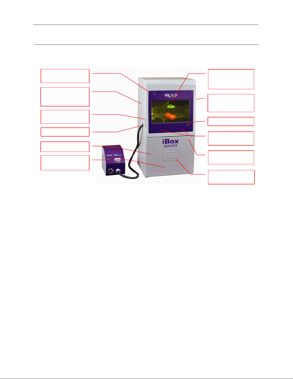
Camera and Lens
Hood
15.6” LCD Touch
Main Power Button
Wide Access Door
USB and SD Card
Access Port
Built-In Overhead
White Lights
Five Position Slide-
Wheel
Sample Viewer
Window
Safety Interlock
Switch & Override
BioLite™ Access
Power Indicator
Lights
Roll-Out
System Components
Refer to the packing slip and pictured components for specific parts and com pon ents included with the
system.
Built Into Darkroom
Warming Plate Tray
Specifications
Power Requirements: 100/115V, 50/60Hz; 3.1 Amps at 120 Volts
230V, 50/60Hz; 1.55 Amps at 230 Volts
Mains supply voltage fluctuations are not to exceed 10 percent of the
nominal supply voltage
Pollution Degree: 2
Installation Category: II
Altitude: Up to 2000m
Ambient Temperature: 5°C to 40°C
Humidity: Maximum relative humidity of 80% for temperatures up to 31°C,
decreasing linearly to 50% maximum relative humidity at 40°C
Built-In Touch Screen Computer
Operating System: Windows® 7, 64-Bit
Connectivity Ports: 2 USB, 1 SD/SDHC/MMC (side of system)
4 USB, VGA and Ethernet (rear of system)
Wireless Networking Capability: 802.11 b/g/n
USB Flash Drive Capacity: 2 GB (minimum)
Internal Hard Drive: 250 GB (minimum)
Software: TS2 (Touch Screen) Software
Screen with Built-In
Computer
Out Emission Filter
Page 5

iBox Spectra Imaging System 5
TS2 Software Screen
Camera and Lens
The iBox Spectra is equipped with the MultiCam 310C camera, a scientific-grade color CCD camera
with a resolution of 2.0MP (1600x1200). The MultiCam 310C is equipped with a 12.5-75mm f/1.2 zoom
lens.
All camera settings are factory pre-set for optimum performance when viewing samples under low light
conditions. Contact UVP Technical Support prior to making any adjustm ents to the camera settings.
Darkroom
The darkroom is light tight to provide optimal imaging conditions. Darkroom features include:
Epi (overhead) LED white light
Roll-out warming plate tray
Sample viewer window built into the darkroom door
Five position emission filter wheel
Brackets and built-in power ports for installing optional epi illumination lamps
Safety interlock switch with manual override to disable UV when darkroom door is opened
LCD Touch Screen
The iBox Spectra contains a fully integrated 15.6-inch color touch screen. The touch screen allows the
user to perform a variety of tasks, including previewing, capturing, saving and printing images as well as
selecting preference options, without the use of an external mouse or keyboard.
For users who prefer not to use the touch screen interface, an external keyboard and mouse are
included as standard. These components can be plugged into any available system USB port.
Warming Plate
The warming plate houses electrical heating elements which maintain the surface of the warming plate
at a constant temperature of 37°C to keep animals warm during the imaging process. The warming
plate plugs into a dedicated port inside the iBox darkroom.
BioLite™ MultiSpectral Light Source
The Manual BioLite Multispectral Source is a 150-Watt quartz halogen visible light source designed for
use with ferrule fiber optic bundles. It features a closed optical path to tightly control the output
spectrum, allowing consistent and repeatable measurements with superior signal to nois e. T he BioLit e
features a six-position dimmer permitting variable intensity. The user inserts the excitation filter into the
slot at the front of the BioLite to control the wavelength of light emitted.
TS2 Software
Image analysis and hardware functions for the iBox Spectra
are controlled by the TS2 (Touch Screen) Software interface.
In addition to image preview, capture and save functions, the
TS2 Software controls camera and lens functions (exposure,
aperture, focus and zoom), image printing, lighting and filter
selection, and other user preference s.
For additional information, refer to the TS2 Software User
Manual included with the system or available online at
http://uvp.com/manuals.
Page 6

iBox Spectra Imaging System 6
Focus Target
Focus Target
The UVP Focus Target provides sharp, detailed images to
aid in adjusting the lens and camera settings for ideal
imaging results.
Optional Equipment
UVP offers a variety of optional equipment to support the needs of varying laboratory environments. Refer to
“Replacement Parts and Accessories” at the end of this manual for optional equipment part numbers.
Thermal Printer
The thermal printer provides archive quality, 256 grayscale
prints and five optional cost-effective print sizes.
Thermal Printer
Anesthesia Unit
The anesthesia system is an optional component designed to safely anesthetize up to five small
animals at a time inside the darkroom. The patented non-rebreathing technology safely prevents
backflow of gases into the darkroom. Anesthesia units are available with either isoflurane or
sevoflurane, as well as with or without oxygen regulators. Contact UVP for ordering information.
Anesthesia Kit
Page 7

iBox Spectra Imaging System 7
Setup Instructions
Components
When unpacking the iBox Spectra, the following items will be included:
1. iBox Spectra darkroom
2. Manual BioLite MultiSpectral Light Source
3. Warming plate
4. 455-495nm excitation filter and 515LP emission filter
5. UVP flash drive
6. Power and USB cables
7. Keyboard and mouse
8. Supporting documentation
When unpacking and setting up the system, two people are required to move the darkroom.
Place the darkroom on a flat surface which can provide adequate support for up to 100 pounds.
WARNING: Do not attempt to perform any setup procedures while the system is plugged in or powered on
unless otherwise instructed.
CAUTION: Do not install the system in areas with high moisture, dust or high temperatures. Keep the
equipment away from motors or any other large magnetic equipment apparatus. This system is designed f or
indoor use only.
Connecting the Power Cables
1. Plug the main power cable into the back of the
darkroom and the other end into a surgeprotected power outlet.
Note: It is recommended to leave the power
switch on the back of the system in the ON
position except when the system will not be
used for an extended period of time (one day or
longer).
Note: Do not position the system so that it is difficult to access the power cable and operate the
main power switch at the back of the unit.
2. If insta lling optional epi handheld lamps, place the lamps in the brackets located at the top of the
darkroom. Plug the handheld lamps into the outlets provided inside the darkroom. Place the power
switches located on the outside of the handheld lamps in the ON position.
Installing the Warming Plate
1. Place the warming plate inside the darkroom on top of the Roll-Out Warming Plate Tray.
2. Plug the jumper cord into the outlet located in the upper left back panel of the darkroom.
3. Plug the other end into the warming plate.
NOTE: When the warming plate is plugged into the outlet in the darkroom and the darkroom is turned on, the warming plate will receive a constant supply of power.
Page 8

iBox Spectra Imaging System 8
Epi Light
Filter Cartridge
Installing Emission Filters
To install the 50mm emission filter and any other emission filters:
1. Carefully remove the filter from the protective plastic case, holding the filter at the edges to
avoid placing fingerprints on the glass surface.
2. The filter wheel is located on the right side of the darkroom. Press in on the slide-out filt er
wheel door and the door will pop out slightly. Pull the filter wheel assembly out until it stops.
3. Manually rotate the filter wheel to the desired position. Place the included filter in Position #1.
NOTE: Before placing the filter in the filter wheel, ensure that the text on the edge of the filter
is positioned so it is right side up when facing the installer.
4. Note the position of all installed filters for entry into the Lighting and Filters menu in the TS2
Software (refer to the TS2 Software User Manual for more information).
5. Once all filters have been loaded, slide the filter wheel assembly back into the system. Press
the filter wheel assembly door until the assembly locks into place.
Additional and replacement emission filters are available through UVP. Refer to the “Replacement
Parts and Accessories” s ect io n of this manual for order ing in f ormat ion .
Installing the BioLite MultiSpectral Light Source
1. Plug the power cord into the receptacle on the back
of the BioLite and the other en d into a surgeprotected power outlet.
2. Insert the filter cartridge into the filter port. NOTE: Filters and their cartridges are directional.
Make sure that the label is facing toward the front of
the BioLite. Because of the intense light of the
BioLite, only tempered interference filters should be
used.
3. Remove the plug from the access port at the upper left side of the darkroom.
4. Insert the knurled side of the fiber optic cable through the hole in the darkroom, from the inside of the darkroom out, leaving the two light guides in the darkroom.
5. Remove any existing plates or screws from the mounting bracket so that the epi light guid e br ac ket appears as shown below.
Guide
Bracket
Page 9

iBox Spectra Imaging System 9
Light emitting portion of
Cable faces the front of
the darkroom
Light guide fits snugly in
mounting bracket
Mounting
up
Use 2
Cable Connection
6. Position the light guide in the mounting bracket as shown below. Make sure the cable protruding
from the light guide faces toward the front of the darkroom (toward the darkroom door) and that the
light emitting portion of the light guide is facing toward the platform tray.
the light guide is facing
platform tray
7. Attach the mounting bracket plate to the mounting bracket using two of the screws provided. Make sure the tab on the plate faces up.
bracket
plate with
tab facing
screws to
secure
plate to
bracket
8. Insert the fiber optic bundle into the silver conne ctor on the front of the BioLite. Attach the cable to the silver connector with the black set screw.
Page 10

iBox Spectra Imaging System 10
Computer
Power
Lights
Using the System
Powering Up the System
Set the black power switch on the back of the
system to the ON (I) position. Once plugged into a
surge-protected wall outlet an d the black pow er
switch on the back of the system is placed in the
ON (I) position, the iBox Spectra is always
powered on. Press the Computer Power button
on the front of the system to power on the internal
computer/touch screen and ac cess controls for the
camera, lenses, lighting and other functions.
The Power Indicator Lights on the front of the unit indicat e w hen
the system’s main power and optional ultraviolet illumination are on.
Main Power will illuminate green when the black main power switch
on the back of the uni t is in the ON (I) position (this does not indicate
that the internal computer or touch screen are on) . Ultraviolet On
will illuminate red when any optional ultraviolet illumination is active
within the darkroom.
The POWER button will illuminate blue when the internal computer
and touch screen are on. (Note: The black main power switch on the
back of the unit must be in the ON (I) position in order for the internal
computer and touch screen to function.)
Note: It is recommended to leave the power switch on the back of the system in the ON position except
when the system will not be used for an extended period of time (one day or longer).
Operating the TS2 Software Interface
Indicator
Power
Button
Upon startup, the internal computer will proceed throu gh t he boot-up process. When complete, the screen
will display the Windows desktop. The TS2 Software screen, similar to the one below, will automatically
open shortly thereafter.
To exit the TS2 Software interface, press either the close (X) or minimize (_) buttons at the top right corner
of the software (see red circle above). To power down the system, exit the TS2 Software interface by
pressing either the close (X) or minimize (_) buttons at the top right of the software. Then, u sing the
Windows “Start” menu, select “Shut Down”.
Refer to the TS2 Software User Manual for further instructions on using the softwar e.
Page 11

iBox Spectra Imaging System 11
Selecting Emission Filters
See the “Installing Emission Filters” section of this manual for instructions on installing individual emission
filters.
Once all filters have been installed, select the Lighting and Filters menu in the TS2 Software and click the
Reset Wheel button under the “Filters” tab to realign and calibrate the filter wheel within the system.
Using the Overhead (Epi) Lighting
To operate the built-in overhead white light, use the Lighting and Filters menu in the TS2 Software and
select White under Epi Illumination.
Using the Warming Plate
NOTE: When the warming plate is plugged into the outlet in the darkroom and the darkroom is turned on,
the warming plate will receive a constant supply of power. The warming plate must be turned off or
unplugged after use, as the software does not control the function of the warming plate.
Ensure that the warming plate on/off switch is turned on.
The warming plate will show the temperature of the warming plate in the display. In several
minutes, the warming plate will reach 37°C.
NOTE: The warming plate has an over limit switch that prevents the unit from exceeding 41°C. Should the
unit reach 41°C, the plate must be returned to a temperature of 25°C before the unit reheats.
NOTE: Allow the warming plate to reach room temperature prior to operating. If the unit is extremely cold
when switched on, the warming surface temperature can exceed the preset temperature indicated on the
LCD display.
Using the Sample Viewer Window
The Sample Viewer Window, built into the darkroom door, allows users to view the interior of the darkroom
without opening the darkroom door.
To open the Window, press firmly on the top of the Window cover to release the pressure-sensitive cla sp
and open the viewer. The Window glass provides a clear view to the warming plate surface for sample
viewing without opening the darkroom door. In the case that ultraviolet illumination is being used in the
darkroom, the Viewer Window also blocks the user from harmful exposure to UV light.
NOTE: To avoid light leakage, close the Sample Viewer Window prior to capturing a light-sensitive image.
Image Focusing
Prior to capturing an image, prepare the image focus:
1. Turn on the white epi illumination and place the Focus Target (see the “Focus Target” section of
this manual for more information) on the warming plate surface.
2. Using the TS2 Software, click to turn ON the “Live Preview” button. Adjust the exposure, aperture,
zoom (if applicable) and focus controls on the bottom portion of the TS2 Software screen until an
ideal image is visible.
Setting the White Balance
Prior to capturing images using the iBox Spectra, calibrate the system’s white balance. White balance
calibration, in essence, is the process of removing unrealistic color casts so that objects which appear white
in person are rendered white in the captured image. This ensures that the white color in the image is as
close to neutral white as possible and all of the colors in the image also appear true.
Page 12

iBox Spectra Imaging System 12
To calibrate the white bala nce :
1. Place a focus target or business card on the warming plate inside the darkroom.
2. From the main TS2 screen, turn on the epi white illumination as well as the Saturation Warning.
3. Using the Live Preview and Focus functions, focus the image.
4. Remove the focus target or business card from the darkroom.
5. Place a sheet of clean white paper on top of the warming plate inside the darkroom and shut the
darkroom door.
6. Access the Preferences menu from the main TS2 screen and ensure that the “Autocapture Image
Contrast” is set to Best. Press OK to close the Preference s menu .
7. After ensuring that the epi white illumination is still on, touch the Auto Capture button on the left
side of the main TS2 screen.
8. Once the captured image appears on the screen, touch the “i” button to open the image information
screen and press the Set as White Balance button.
9. Touch the “i” button again to close the image information screen. The system’s white balance is
now calibrated.
Page 13

iBox Spectra Imaging System 13
Service Procedures
Return Procedure
A Returned Goods Authorization (RGA) number must be obtained from UVP Customer Service before
returning any product.
Replacement Parts and Accessories
To order accessories or replacement parts for the iBox Spectra Imaging System, contact UVP’s offices.
Part Description Part Number
Fuses:
Fuse, 3.15A (for Darkroom) 56-0022-04 (Qty. 2 Recommended)
Excitation Filters:
Filter Assembly, GFP (455-495nm), Manual BioLite 38-0340-03
Contact UVP for Additional Excitation Filters
Emission Filters:
Filter, 515nm Long Pass, 50mm Square 38-0364-01
Contact UVP for Additional Filters
Troubleshooting
No Power to the Darkroom or Warming Plate
1. Recheck the main power cord connection to the iBox Spectra darkroom as well as the power
cables between the darkroom and warming plate or optional handheld lamps .
2. Check the fuses located at the back of the unit next to
the power port. A small flat-head screwdriver or similar
tool will be required. Push the bottom tab of the
fuseholder up until the fuseholder’s bottom pops out.
Then, push the top tab down until the top pops out.
The entire fuseholder can now be pulled out.
Inspect the thin wire within each glass fuse to see if
there is a break in the wire. If so, replace the fuse(s). If
fuses are blowing repeatedly, contact UVP Technical
Support for additional troubleshooting.
Error Messages Appear on the Screen
1. An error message that is related to the TS2 software interface or Microsoft Windows may appear
on the screen. If the message is related to Microsoft Windows, such as a reminder to activate or
update the copy of Windows, please contact your system administrator for assistance.
2. If an error message appears repeatedly and your system administrator does not recognize it as a
Microsoft Windows error, contact UVP Technical Support for further assistance.
Care and Cleaning
Use only mild soap or detergent solution for cleaning. Do NOT use oil- or petroleum-based cleaners for the
cabinet. Ensure that the system is turned OFF and unp lugg e d during cle anin g.
Page 14

iBox Spectra Imaging System 14
Technical Support
UVP offers free lifetime technical support on all of its products and software. Should you have any questions
regarding the product’s use, operation or repair, contact UVP’s offices at the locations below, or visit
www.uvp.com.
If you are in North America, South
America, East Asia or Australia:
Call (800) 452-6788 or (909) 946-
3197, and ask for Technical Support
during regular business days, between
7:00 am and 5:00 pm, PST.
E-mail your message to:
info@uvp.com
Fax Customer Service, and send it to
(909) 946-3597
Write to: UVP, LLC 2066 W. 11th
Street, Upland, CA 91786 USA
If you are in Europe, Africa, the
Middle East of Western Asia:
Call +44(0) 1223-420022, and ask for
Customer Service during regular
business days between 9:00 am and
5:30 pm.
E-mail your message to: uvp@uvp.co.uk
Fax Customer Service, and send it to:
+44(0) 1223-420561
Write to: Ultra-Violet Products Ltd
Unit 1, Trinity Hall Farm Estate, Nuffield
Road, Cambridge CB4 1TG UK
iBox is a registered trademark of UV P, LLC.
Spectra and BioLite are trademarks of UVP, LLC.
 Loading...