

Page 1
Ultra-Violet Products Ltd.
2
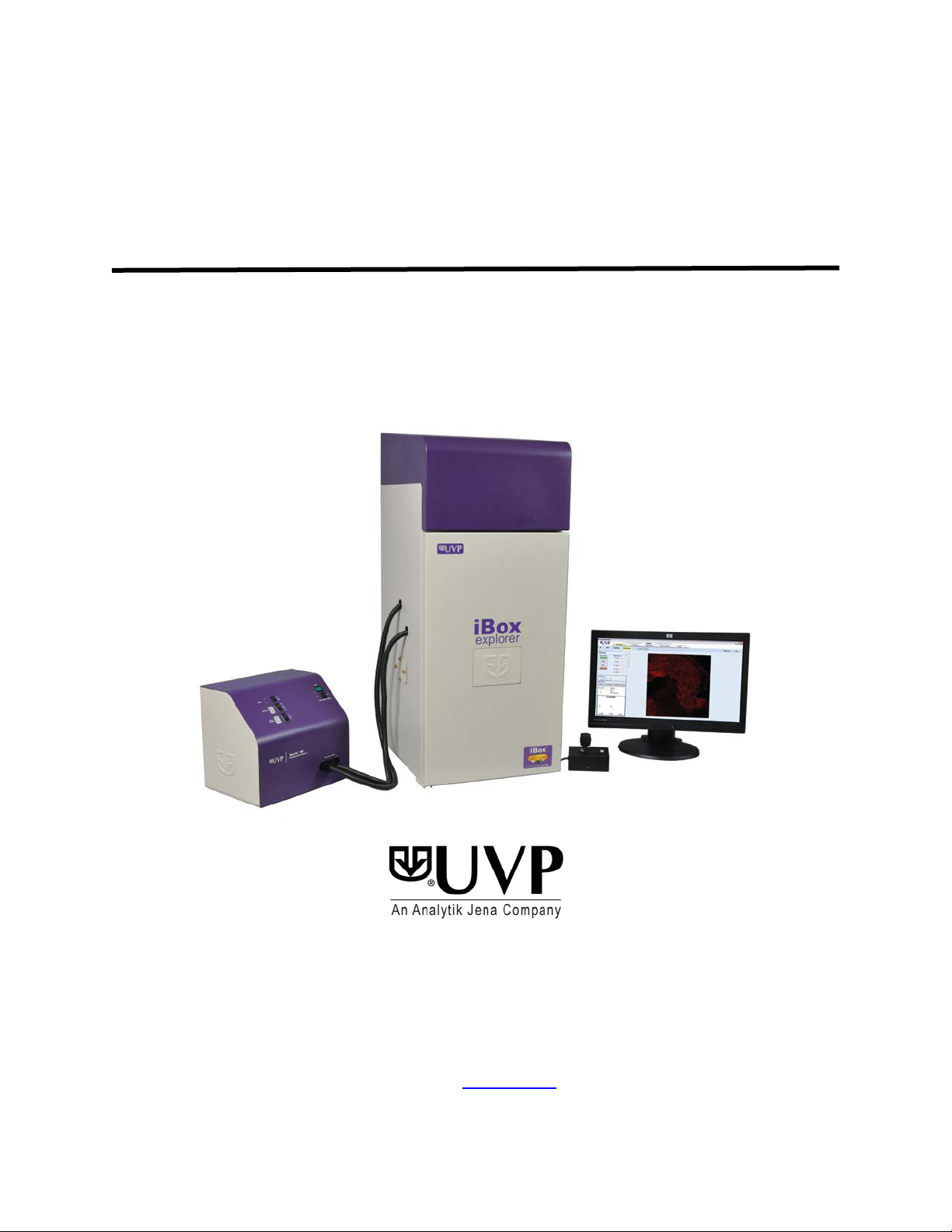
iBox
Explorer Imaging Microscope
®
Instruction Guide
______________________________________________________________________________
UVP, LLC
2066 W. 11th Street, Upland, CA 91786
Tel: (909) 946-3197 / (800) 452-6788
Fax: (909) 946-3597
Web Site:
Nuffield Road, Cambridge CB4 1TG UK
Tel: +44(0)1223-420022 Fax: +44(0)1223-420561
www.uvp.com
Unit 1, Trinity Hall Farm Estate
81-0342-01 Rev E
Page 2

iBox Explorer2 2
Table of Contents
Table of Contents ......................................................................................................................................................... 2
Introduction .................................................................................................................................................................. 3
Safety Information ........................................................................................................................................................ 4
Components ................................................................................................................................................................. 5
Specifications ............................................................................................................................................................ 6
Darkroom Cabinet ..................................................................................................................................................... 6
Four Position Filter Tray ............................................................................................................................................ 6
CCD Camera and Objectives .................................................................................................................................... 6
Magnification and Field of View ................................................................................................................................. 6
Viewer Window .......................................................................................................................................................... 6
Motorized Sample Platform ....................................................................................................................................... 6
Warming Plate ........................................................................................................................................................... 6
VisionWorksLS Software ........................................................................................................................................... 6
BioLite Xe MultiSpectral Source ................................................................................................................................ 6
Installation .................................................................................................................................................................... 7
Installing the Software ............................................................................................................................................... 7
Registering the Software ........................................................................................................................................... 7
Installing the Hardware .............................................................................................................................................. 9
BioLite Xe MultiSpectral Light Source Setup ........................................................................................................... 10
Fiber Optic Cable Connection ................................................................................................................................. 11
Platform Stage/Warming Plate ................................................................................................................................ 12
Additional iBox Explorer
Loading Drivers ....................................................................................................................................................... 13
Operation .................................................................................................................................................................... 14
Preparing the System .............................................................................................................................................. 14
Preparing to Capture Images .................................................................................................................................. 15
Capturing Images .................................................................................................................................................... 18
Service Procedures .................................................................................................................................................... 19
Care and Cleaning .................................................................................................................................................. 19
Return Procedure .................................................................................................................................................... 19
Troubleshooting ....................................................................................................................................................... 19
Replacement Parts and Accessories ....................................................................................................................... 20
Technical Support ................................................................................................................................................... 21
2
Connections .................................................................................................................... 13
Page 3

iBox Explorer2 3
Introduction
The iBox Explorer2 Imaging Microscope is designed to automate research with one-touch preset or user-defined PC
controls for accurate, repeatable imaging and analysis of animals and plants. The iBox Explorer
tight darkroom with VisionWorks
wide range of magnification settings, allowing visualization from an entire small animal down to the cellular level
subcutaneously and within the body cavity of living mice.
The darkroom has a door-mounted viewing window, four-position emission filter tray with four emission filters
included, and a software- and joystick-controlled imaging platform. The system comes with dual-pat h dire cte d lighti ng
for exciting samples with the BioLite™ Xe MultiSpectral Light Source. The BioLite Xe offers an eight-position filter
wheel, six-position intensity selector, and a direct lighting source using fiber optic bundles to tightly control the output
spectrum for consistent, repeatable measurements. Two excitation filters are included, one each for the excitation of
GFP (Green Fluorescent Protein) and RFP (Red Fluorescent Protein).
2
The iBox Explorer
stage surface at a constant 38°C. The warming plate also contains two threaded studs to accommodate a small
animal anesthesi a manifold .
The iBox Explorer
preview images.
Imaging Microscope comes equipped with a slide-out warming plate that maintains the platform
2
includes a highly sensitive CCD camera with high magnification optics, providing real-time, live
LS Acquisition & Analysis software for automated control. The system provides a
2
incorporates a light
iBox Explorer2 Imaging Microscope
Page 4

iBox Explorer2 4
Safety Information
Do not use this equipment in a manner other than as stated in these instructions.
This equipment is designed for use in a laboratory environment by personnel knowledgeable in safe laboratory
practices. Pro per prec autions must be taken as potential electri cal and me chan ical hazards are inherent in the
use of this equipment.
CAUTION: While UVP’s warming plate is designed for the safety of users, care should be taken when operating
the unit as the platfor m stage can be hot.
Page 5
iBox Explorer2 5
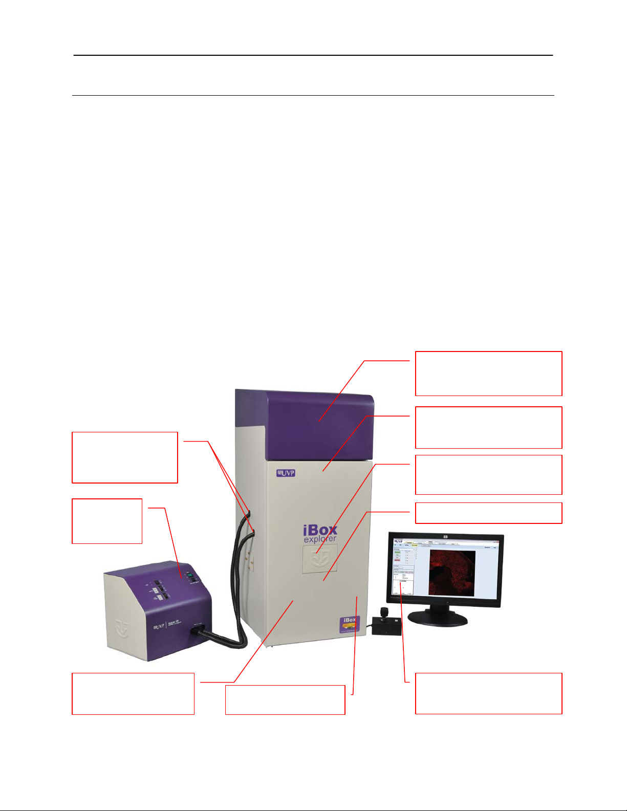
Monochrome CCD camera and
Four position filter tray with
Access ports for
Source
Viewer window opens for
amber screen
Light tight darkroom with
wide access door
Software controlled
platform adjusts on the
Warming plate
VisionWorks®LS software
image capture & image analysis
BioLite Xe
Components
The iBox Explorer2 Imaging Microscope is comprised of the following components:
Darkroom Cabinet
Joystick
CCD Camera/Optics (internal and not visible)
Sample Viewer Window and Internal Amber Screen
Motorized Platform
Slide-Out Warming Plate
Emission Filters (GFP, RFP, 515 Long Pass, Neutral Density)
Excitation Filters (GFP, RFP)
BioLite Xe MultiSpectral Light Source
VisionWorksLS Software
Please review the packing slip for a complete equipment list. System components may vary.
Note: The system may also include a computer and monitor.
magnification objectives are
housed inside the darkroom
BioLite Xe
MultiSpectral Light
with indicator
lights
X, Y and Z axes
RFP, GFP, 515 Long Pass and
Neutral Density filter s in clud ed
sample observation through
controls darkroom functions,
Page 6

iBox Explorer2 6
Specifications
Power Requirements: 100-230V; 6.3 Amps at 120 Volts
Mains supply voltage fluctuations are not to exceed 10 percent of the nominal supply
voltage
Pollution Degree: 2
Installation Category: II
Altitude: Up to 2000m
Ambient Temperature: 5°C to 40°C
Software Requirements: Windows XP (SP2) or Windows 7 (32-bit and 64-bit versions)
Humidity: Maximum relative humidity of 80% for temperatures up to 31°C, decreasing linearly
to 50% maximum relative humidity at 40°C
Darkroom Cabinet
The iBox Explorer2 is constructed of aluminum and fabricated to provide a light tight chamber. Darkroom
dimensions are 17.5”W x 20”D x 42”H (44.5cm x 50.8cm x 106.7cm).
Four Position Filter Tray
The filter tray accommodates up to four removable emission filters. The iBox Explorer2 system includes RFP
(Red Fluorescent Protein), GFP (Green Fluorescent Protein), 515 Long Pass and Neutral Density emission
filters. VisionWorksLS software controls the selection of filters. Additional filters are available through UVP.
CCD Camera and Objectives
The high-sensitivity CCD camera and fast optics, housed in the top of darkroom, generate high resolution
images. The camera and motorized optics are controlled by VisionWorksLS software.
Magnification and Field of View
The iBox Explorer2 contains a combination of relay and objective lenses, providing magnifications of 0.17x,
0.25x, 0.50x, 1.66x, 2.50x, 4.50x, 7.50x, 8.80x and 16.5x. The corresponding fields of view are 90mm2, 60mm2,
2
, 9mm2, 6mm2, 3.3mm2, 2mm2, 1.7mm2 and 0.9mm2.
30mm
Viewer Win dow
The viewer window, built into the darkroom door, opens for sample viewing.
Motorized Sample Platform
The motorized sample platform, controlled by the joystick, can be adjusted in the X, Y and Z dimensions. The
platform can be moved 100mm in each direction.
Warming Plate
The warming plate creates a constant temperature of 38ºC for the warming of animal specimens. The dark
background creates an ideal imaging surface while maintaining a constant temperature for the animal.
VisionWorksLS Software
The VisionWorksLS Acquisition & Analysis software controls the darkroom functions and lighting as well as the
motorized optics and camera. T he softwar e is operational on both 32-bit and 64-bit Windows operating systems.
BioLite Xe MultiSpectral Source
The BioLite Xe MultiSpectral Source provides dual path excitation lighting for specimens. GFP and RFP filters
come standard with the BioLite Xe, and custom filters for specif ic appl ic ations are also available. Refer to
“Replacement Parts and Accessor ies” for orderi ng information.
Page 7
iBox Explorer2 7
Installation
Installing the Software
Insert VisionWorksLS CD (not network CD) into the computer.
Click on the Install button for VisionWorksLS.
Click OK, Next, agree to “I accept terms of licensing agreement”, then Next. Leave all options in
their default settings. Then click Next, Next, Install and finally Finish.
Registering the Software
Open the Software
Double click VisionWorksLS software icon
on the desktop.
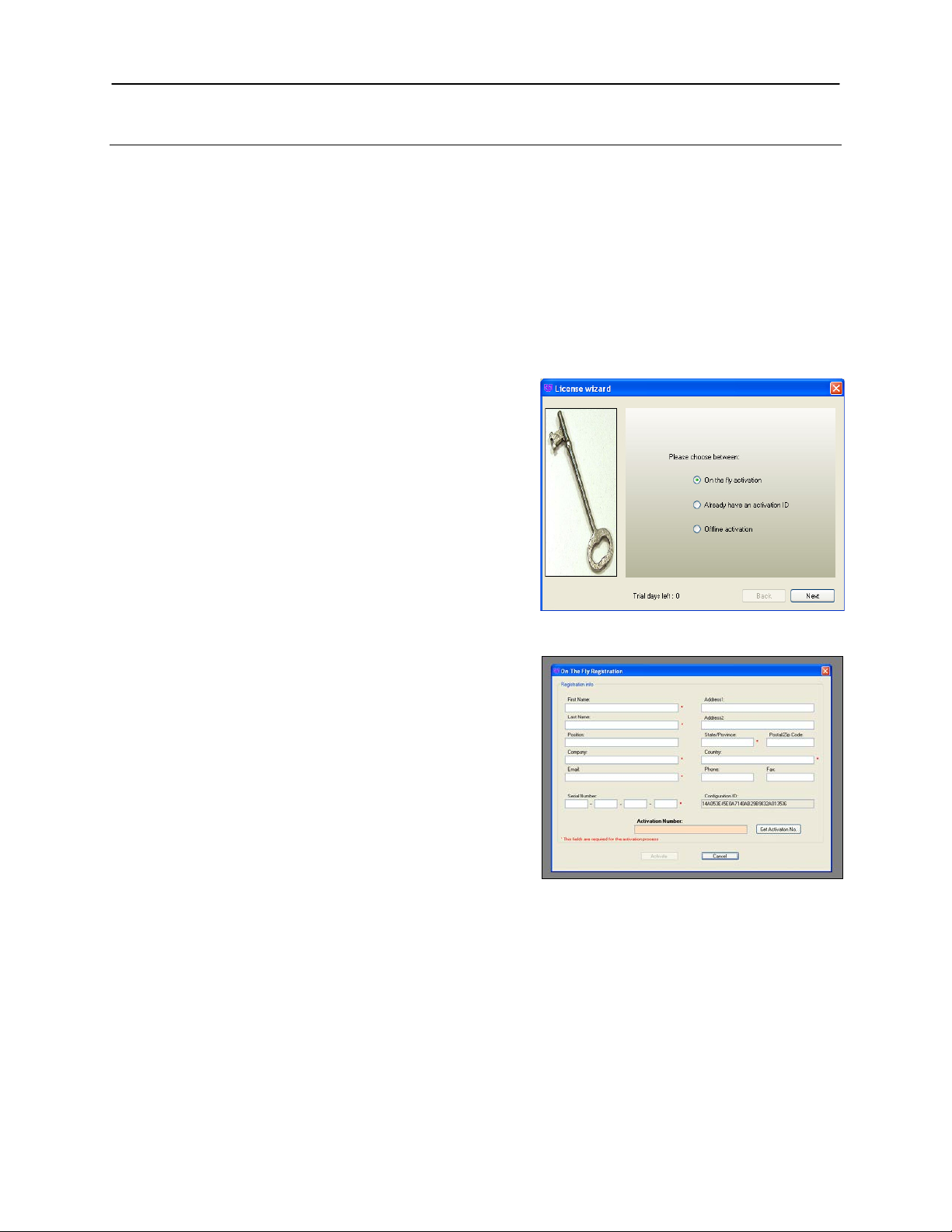
To activate the software, registration is
required. To immediately activate the
software online, choose On-the-Fly
activation. If the computer is not
connected to the Internet, select Offline
activation and proceed to the following
page of this manual, or call UVP to register
the software.
Click Next to continue.
The Already have an activation ID option
is useful when reloading the software after
receiving an initial activation code.
Complete all required information on the
form.
Fill out the Serial Number located on the
CD. The number should be four sets of six
numbers.
Once the form is completed, click on Get
Activation No. and then click Activate
once the Activation Number appears in the
box.
Page 8

iBox Explorer2 8
If the computer is not connected to the
Internet, click Offline activation to register
the software. This allows the user to obtain
the activation code and enter it at another
time.
Click Next to continue.
Click the link provided and complete the
form to obtain instructions. Click Finish.
Page 9

iBox Explorer2 9
Filter Position #1 – 515 Long Pass
Filter Position #2 – 535/45 GFP
Filter Position #4 – Neutral Density
Filter Position #3 – 605/50 RFP
Filter Tray
Filter Holder
Lip facing up
Filter tray well door
Installing the Hardware
Darkroom Setup
When unpacking and setting up the darkroom, tw o people ar e requ ired to mov e the darkroom.
Place the darkroom on a flat surface which can provide adequate support for up to 120 pounds.
NOTE: This system is designed for indoor use only.
Darkroom Filter Setup
Place the filters into the filter tray in the appropriate positions as noted bel ow. Once all filters are in
place, position the magnetic filter holder over the filter tray to hold the filt ers in plac e.
Open the darkroom door
and slide the filter tray
well door open. Place the
filter tray into position with
the lip facing up (note that
the filter must be set to
position #2 in
VisionWorksLS in order
for the filter tray to be
inserted or removed).
Page 10

iBox Explorer2 10
Note: Image shown may appear different from the product
USB Cable
Power Cord
Dichroic splitter
cube door
Dichroic splitter
cube
Dichroic Splitter Cube Installation
The dichroic splitter cube is used
to direct coaxial lighting down
through the magnification
objectives while allowing sample
emission lighting to pass through
to the camera.
Slide the dichroic splitter cube door
open to the left (the door is
embossed with the UVP logo) and
fully insert the dichroic splitter
cube. Fully slide the door to the
right once the cube is in place.
Camera Assembly
The system will come shippe d with the camera and objectives instal led from the factory. No
additional assembly is required.
BioLite Xe MultiSpectral Light Source Setup
shipped.
Position the BioLite Xe to the left of the darkroom,
turn off the unit and unplug the power cord.
The xenon bulb assembly will come separate from the
BioLite Xe and is equipped with a male connector on
one end and a female connector on the other.
CAUTION: Wear safety glasses when handling the
xenon bulb assembly! The bulb is under high
pressure and can explode if dropped or mishandled.
To insert the bulb, lay the BioLite Xe on its back so
that the bottom of the unit is exposed. Connect the
male connector from the bulb to the female conne ctor
in the BioLite Xe and vice versa.
CAUTION: Do not touch the glass portion of the
xenon bulb assembly! Residual fingerprint oils can
cause the bulb to explode during use.
Connect the bulb base plate to the bottom of the unit
using the three supplied nuts.
Return the BioLite Xe to the upright position. Plug the
power cord into the receptacle on the back of the unit
and to a power outlet. Connect the USB cable to the
back of the unit and to the computer.
Page 11

iBox Explorer2 11
Plug the upper
BioLite Xe unit.
Plug the lower fiber
Filter
Filter
Ridge
Magnetic
Filters are installed in their black casing at the UVP factory.
To insert the filter/holder into the filter wheel, hold the
assembly so that it is positioned vertically with the ridge
to the top left as shown in the photo.
The filter/holder ridge is then positioned closest to the
front of the unit.
access
port
Manually rotate the filter wheel to select the desired
filter position.
1. Load the GFP filter in position number one as
noted on the BioLite Xe filter wheel.
2. Load the RFP filter in position number two as
noted on the BioLite Xe filter wheel.
NOTE: Do not force the filter assembly inside the BioLite Xe wheel
slot. If the filter assembly does not easily insert, check to ensure that
the orientation of the assembly is correct.
Tab
access
port
Fiber Optic Cable Connection
The iBox Explorer2 has two black fiber optic cables coming out of the left side of the unit.
Remove the soft rubber cap from the tip of each of the black fiber optic cables.
Plug the lower fiber optic cable into the left port (Epi/Coaxial) on the BioLite Xe unit.
Plug the upper fiber optic cable into the right port (Trans/Side) on the BioLite Xe unit.
fiber optic cable
into the right port
(Trans/Side) on the
optic cable into the
left port
(Epi/Coaxial) on the
BioLite Xe unit.
Page 12

iBox Explorer2 12
Plug the fiber
rubber caps
Adjustable
Warming plate
display
Warming plate
On/Off switch
Slide-out
warming plate
Temperature
control buttons
optic cables into
the appropriate
ports after
removing the soft
Platform Stage/Warming Pla te
The platform stage contains a built-in retractable warming plate. The w ar ming plat e is able to be shut off
using the switch on the warming plate control box and the temperature of the plate can be adjusted using
the two black buttons below the control box LCD display.
amber filter
viewer for
enhanced
sample
viewing under
blue light
controller box
with LCD
temperature
NOTE: Allow the warming plate to reach room temperature prior to operating. If the unit is extremely cold
when switched on, the warming surface temperature can exceed the preset temperature indicated on the
LCD display.
Page 13

iBox Explorer2 13
Additional iBox Explorer2 Connections
Plug the USB cable into the back of the darkroom cabinet and the other end into the computer. This
cable allows the user to control all iBox Explorer2 hardware including magnif ica t io n, camer a and filter
selection through VisionWorksLS.
Plug the joystick cable into the back of the darkroom cabinet.
Plug the power cord into the back of the darkroom cabinet and the other end into a wall outlet.
Turn the darkroom ON (power switch is located on the lower bac k side of the darkroom).
NOTE: Be sure to click the “Disconnect” button in VisionWorksLS before disconnecting any hardware
from the computer.
Loading Drivers
Open VisionWorksLS software.
Turn the darkroom ON if not already powered on (power switch is located on the lower back side of
the darkroom).
Install the camera driver:
o When the camera is first connected to the computer, the Found New Hardware wizard will
open. Select “Install from a list or specified location (Advanced)” and click the Next button.
o Select “Don’t Search. I will choose the driver to install”. Then click the Next button.
o Click the Have Disk… button and browse to the C:\Windows\system32\drivers folder. Sele ct
the AltaUSB.inf file and select Open and then OK to install the camera.
o Select Finish.
Install the darkroom driver:
o Load the small disk that was shipped with the system to enable functionality of the darkroom.
o NOTE: If you do not have a tray-loading CD/DVD drive with an inset for loading a smaller disk,
contact UVP Technical Support for further assistance.
Page 14

iBox Explorer2 14
Preparing the System
Operation
Turn on the darkroom and the BioLite Xe prior to opening the software to enable the hardware connection.
Note that the iBox Explorer
system is powered on.
Open VisionWorksLS software which controls the iBox Explorer
2
will perform a three-minute calibration and self-test procedure each time the
2
system and the BioLite Xe.
To operate the darkroom controls, click on the “Acquisition” tab in VisionWorksLS. The software operates
the objectives (lenses), emission filters and BioLite Xe lighting.
The purpose of the Action Tabs is to enable quick selection of major tasks.
o Acquisition: Options to change camera, darkroom, lens etc. settings to obtain an image
o Image: Options to apply image filters, brightness & contrast, pseu doc olors, annotations and
other tools to alter the appearance of the image
NOTE: 1D Analysis, Area Density and Colony Counting tabs are shown in the software but are
grayed out as they are not applicable.
Page 15

iBox Explorer2 15
Setting
Relative Intensity
6
100%
5
50%
4
40%
3
25%
2
12%
Excitation
Filter
Light Intensity
Illumination
Preparing to Capture Images
Platform Stage/Warmin g Plate
The platform stage/warming plate creates a constant temperature of 38ºC to warm and prevent hypothermia in
animal specimens. Slide out the platform stage and place the specimen on the warming plate of the iBox
Explorer
the animal.
For samples that do not require heat, it is possible to disable the warming component of the platform stage by
moving the switch on the warming plate control box to the OFF position.
2
. The dark background creates an ideal imaging surface while maintaining a constant temperature for
Selecting Excitation Filters and Lighting
VisionWorksLS provides automated control of the BioLite Xe excitation filters and lighting via the Lighting
menu. Note that it is possible to control the BioLite Xe manually via the controls on the front of the unit;
however, this is not recommended as any changes made may not be reflected in VisionWorksLS.
Select from one of eight excitation filters (GFP and RFP are included) using the “Filter” drop-down
menu shown.
Select the “On” radio button next to “Light Engine”.
Light intensity is selected via the “Intensity” slider, with intensities ranging from 1 (minimum) to 6
(maximum). The relative outputs for each setting are:
1 0%
Select the illumination path through the “Illumination” menu (either side or coaxial lighting).
Path
Page 16

iBox Explorer2 16
The camera and its various settings are controlled via the Camera menu button. Here, the user can selec t
Joystick
Speed Adjustment
Selecting Emission Filters
Filter selection is controlled via the Microscope menu.
Select the appropriate emi ssion filter from the available
buttons (note that the Clear/Neutral Density filter simply
reduces the total amount of light that is allowed to pass
through the filter).
Selecting Microscope Magnification
Microscope magnification is controlled via the
Microscope menu. There are nine imaging
magnification objectives to choose from. Select the
desired magnification object iv e from the available radio
buttons.
For initial focusing, it is recommended to begin at the
0.17x setting, focus the image, and then move to the
next higher magnification. Additionally, parfocusing
allows the user to focus at a higher magnification then
move to a lower magnification without losing focus.
The iBox Explorer
Optical
Magnification
2
’s various magnification setting s provide the following fields of view:
0.17x 0.25x 0.50x 1.66x 2.5x 4.5x 7.5x 8.8x 16.5x
Field of View
(mm
2
)
90 60 30 9 6 3.3 2 1.7 0.9
Camera Control
from a variety of settings, including exposure time, binning and templates.
Adjusting the Sample Platform
The sample platform position is adjusted using the joystick.
Adjust the sample platform height (Z movement) by twisting the joystick handle left and right.
Adjust the X and Y movement (left and right, or forward and back) by moving the joystick handle right
and left, fore and aft.
The green “turbo” button on the joystick box is used to toggle between slow and quick platform
movement.
Page 17

iBox Explorer2 17
Fine Focus
Viewer
Window
While twisting the joystick handle will cause quick
vertical movements of the sample platform, the “+”
and “–“buttons under the Microscope menu on
VisionWorksLS are used for minor vertical
adjustments of the platform. This allows for detailed
focusing adjustments.
Bookmarks
Using VisionWorksLS Bookmarks feature, it is possible
to temporarily store various platform positions. When the
user desires to store the current platform position, click
the “New” button under the “Bookmarks” section of the
“Microscope” tab. Enter a name for the bookmark for
reference.
“New” allows the user to save a new bookmark.
“Update” allows the user to update the name or
location of an existing bookmark.
“Delete” allows the user to delete the selected
bookmark.
“Clear” deletes ALL stored bookmarks.
NOTE: Once VisionWorksLS is closed, all bookmarks
will be deleted.
Viewer Window
The Viewer Window is located on the front of the darkroom door and has a pressure-sensitive clasp. Press
firmly at the top of the cover to open the viewer. The window provides a view to the imaging platform surface for
visibility of samples without opening the door.
Page 18

iBox Explorer2 18
Preview
Button
Excitation
Filter
Light Intensity
Illumination
Capturing Images
Prior to image capture, use the Preview button to adjust image focus, exposure, location, etc.
For excitation lighting, use the BioLite Xe to view the sample with:
o Side lighting for low magnification imaging and
o Coaxial lighting for high magnification imaging.
Use VisionWorksLS software to:
o Select the appropriate filter and
o Select the desired intensity.
Adjust the position of the
stage using the joystick as
described in Adjusting the
Sample Platform.
Adjust the exposure time,
binning and region of
interest (ROI) while in the
Preview window.
Begin by focusing with the
lowest magnification. Then,
increase the magnification
by one level and fine focus
the image. Repeat this
process until the desired
magnification is achieved.
Again, the Bookmarks tool
is available to temporarily
store locations and
magnifications at those
locations.
Page 19

iBox Explorer2 19
Service Procedures
Care and Cleaning
CAUTION: Warming plate surface can be hot. Let the plate cool prior to cleaning the unit.
To clean the unit:
• Unplug the unit from the power source prior to cleaning.
• Use mild soap and water with a soft cloth or sponge to clean the exterior of the unit.
• Mild isopropyl alcohol or bleach can be used to clean the surface of the unit.
CAUTION: If cleaning agents other than those recommended by UVP are used, a reaction with parts or
materials contained within the warming plate may pose a potential hazard. Contact UVP Technical Support
(contact information listed below) if there are questions regarding the materials used for decontamination or
cleaning.
Return Procedure
A Returned Goods Authorization (RGA) number must be obtained from UVP Customer Service before
returning any product or component.
Troubleshooting No Power to the Darkroom
1. Recheck the main power cord connection to the iBox Explorer2 darkroom.
2. Check the fuses located at the back of the unit next to
the power port. A small flat-head screwdriver or similar
tool will be required. Push the bottom tab of the
fuseholder up until the fuseholder’s bottom pops out.
Then, push the top tab down until the top pops out.
The entire fuseholder can now be pulled out.
Inspect the thin wire within each glass fuse to see if
there is a break in the wire. If so, replace the fuse(s). If
fuses are blowing repeatedly, contact UVP Technical
Support for additional troubleshooting.
When reinstalling the fuses and fuseholder, make sure that both the bottom and top fuseholder
tabs click firmly into place.
Page 20

iBox Explorer2 20
Replacement Parts and Accessories
Replacement parts and accessories part numbers are shown below. To order accessories or replacement
parts, including excitation and emission filters, contact UVP’s offices listed under Technical Support.
Part Description Pa r t Number
Fuse, 3.2 Amp 56-0002-05 (Qty. 2 Required)
Power Cord, 100V/115V 46-0023-38
Power Cord, 230V 46-0023-39
Additional or Replacement Excitation/Emission Filters Contact UVP for Details
Four-Position Filter Holder Assembly 76-0400-01
Thermal printer, digital archive quality 256-grayscale (Mitsubishi) 89-0069-06 (115V)
Thermal printer, digital archive quality 256-grayscale (Mitsubishi) 89-0069-07 (230V)
Thermal printer, digital archive quality 256-grayscale (Sony for Europe) 89-0069-15 (230V)
Thermal paper, Mitsubishi (4 rolls – 800 images) 89-0038-01
Thermal paper, Sony high gloss (5 rolls – 1000 images) 89-0174-01
Thermal paper, Sony glossy (5 rolls – 1000 images) 89-0031-01
Anesthesia Unit: The anesthesia system is an optional component designed to safely anesthetize one
small animal at a time inside the darkroom. The pat en ted no n-rebreathing technology safely prevents
backflow of gases into the darkroom. Anesthesia units are available with either isoflurane or sevoflurane, as
well as with or without oxygen regulators. Contact UVP for ordering information.
Page 21

iBox Explorer2 21
Technical Support
UVP offers expert technical support on all UVP products. If there are any questions about product use,
operation or repair, contact UVP’s offices at the locations below.
NOTE: A Returned Goods Authorization (RGA) number must be obtained from UVP’s Customer Service
prior to returning any product.
If you are in North America, South America,
East Asia or Australia:
If you are in Europe, Africa, the Middle East or
Western Asia:
Call (800) 452-6788 or (909) 946-3197, and ask
for Technical Support during regula r busin es s
days, between 7:00 am and 5:00 pm, PST.
E-mail your message to: info@uvp.com or
techsupport@uvp.com
Fax Technical Support at (909) 946-3597
Write to: UVP, LLC. 2066 W. 11th Street, Upland,
CA 91786 USA
iBox and Vi si onWorks are registered trademarks of UVP, LLC.
BioLite and Explorer are trademarks of UVP, LLC.
Call +44(0) 1223-420022, and ask for Customer
Service during regular business days between 9:00
am and 5:30 pm.
E-mail your message to: uvp@uvp.co.uk
Fax Customer Service at
+44(0) 1223-420561
Write to: Ultra-Violet Products Ltd. Unit 1, Trinity Hall
Farm Estate, Nuffield Road, Cambridge CB4 1TG UK
 Loading...