

Page 1
GelDoc-It
Imager
Installation and User Instructions
e
UVP, LLC Ultra-Violet Products Ltd.
2066 W. 11th Street Unit 1, Trinity Hall Farm Estate
Upland, CA 91786 Nuffield Road, Cambridge CB4 1TG UK
Phone: (800) 452-6788 Phone: +44(0)1223-420022
Fax: (909) 946-3597 Fax: +44(0)1223-420561
Web Site: www.uvp.com
81-0334-01 Rev B
Page 2

GelDoc-Ite Imager 2
e
Introduction
The GelDoc-It® Imager enables easy, efficient and economical documentation and analysis of fluorescent
and non-fluorescent gels, membranes, film, plates and assays. Use UVP’s VisionWorks
Analysis software to capture images, to save images for later quantitative analysis, or for image
enhancement for publication purposes.
The GelDoc-It
FluorCam 220 camera with 1.3MP and optical zoom for ideal image capture. In addition, the Imager’s front
Viewer Window provides a look into the imaging darkroom, while the two side doors offer easy access to the
imaging surface for sample movement or excisi on.
e
Imager contains a built-in UV transilluminator, standard ethidium bromide filter, and a
®
LS Acquis ition and
Page 3
GelDoc-Ite Imager 3
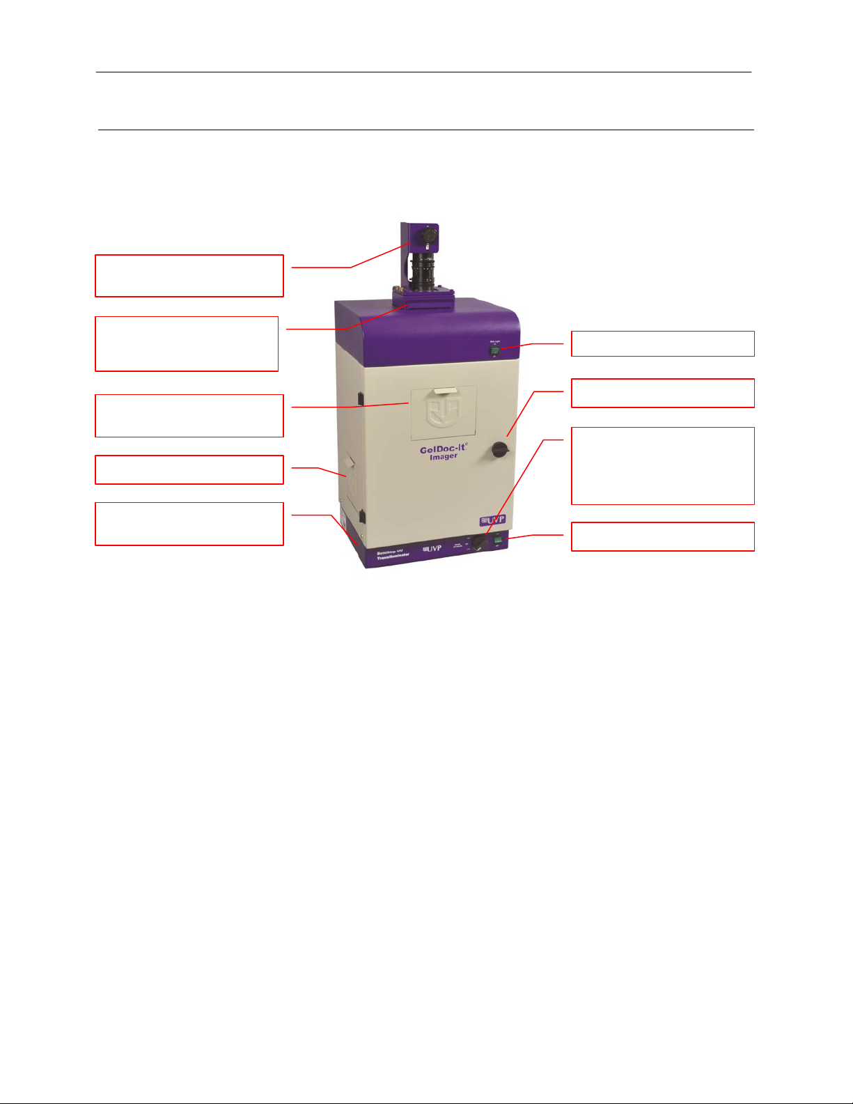
White Light Power Switch
Darkroom Door Lock Knob
Filter Tray (located beneath
Bromide Filter
UV-Blocking Gel Viewer
Integrated UV
FluorCam 220 Camera and
Side Access Doors
UV Power Switch
UV Selector Knob
System Components
Refer to the packing slip and pictured components for specific parts and com pon ents included with the
system.
Zoom Lens
the camera) with Ethidium
Window
(on 2UV™ and 3UV™
models) or Intensity Selector
Knob (Single UV Models)
Transilluminator
Specifications
Power Requirements: 100/115V, 50/60Hz; 3.1 Amps at 120 Volts
230V, 50/60Hz; 1.55 Amps at 230 Volts
Mains supply voltage fluctuations are not to exceed 10 percent of the
nominal supply voltage
Pollution Degree: 2
Installation Category: II
Altitude: Up to 2000m
Ambient Temperature: 5°C to 40°C
Humidity: Maximum relative humidity of 80% for temperatures up to 31°C,
decreasing linearly to 50% maximum relative humidity at 40°C
Minimum Computer Requirements:
Processor: Pentium class, 1.6 GHz or higher
RAM: 1 GB (2GB Preferred)
Display: 1024 x 768
Operating System: Microsoft Windows XP Service Pack 2 or Newer (32-bit or 64-bit)
Internet Browser: Microsoft Internet Explorer 6.0 or later
Computer USB Ports: Computer must come equipped with a minimum of one USB port;
additional peripherals (mouse, keyboard, printer, etc.) may require
additional USB ports.
Page 4

GelDoc-Ite Imager 4
Fluorescent Focus Target
Camera and Lens
The GelDoc-Ite Imager is equipped with a FluorCam 220 camera, a scientific-grade monochrome CCD
camera with a resolution of 1.3 megapixels (1280x1024). The FluorCam 220 utilizes a USB 2.0 PC
connection and is equipped with an 8-48mm optical zoom lens.
All camera settings are factory pre-set for optimum performance when viewing gels, films or
membranes under low light level conditions. Contact UVP Technical Support prior to making any
adjustments to the camera settings.
VisionWorksLS Acquisition and Analysis Software
The GelDoc-Ite is configured with VisionWorksLS Software for acquisition and analysis of gels, plates
and membranes. The software features image enhancement, complete analysis tools and reporting
capabilities, and is ideal for users who require robust image acquisition and analysis functions.
Ethidium Bromide (EtBr) Emission Filter
The ethidium bromide (50mm square) UV-blocking bandpass interference filter blocks UV and IR
radiation emitted from the transilluminator. The filter is placed in the Filter Tray located beneath the
camera/lens assembly. The filter allows visualization of fluorophores from 580-630nm, targeting the
ethidium bromide emission peak of 605nm.
Additional filters are available for other specific fluorophores, including custom filters. Filters can also be
removed when imaging non-fluorescent media (including protein gels, colony plates, etc.) in order to
produce brighter images. Contact UVP for filter ordering information.
Darkroom
The GelDoc-Ite Imager’s darkroom features includ e:
Integrated UV transilluminator (available in 3UV, 2UV and single UV models)
Epi (overhead) LED white light
UV-Blocking Gel Viewer Window built into the darkroom door
Two side doors for easy access to the imaging surface
Single position emission filter tray
UV safety interlock switch to disable UV transillumination when darkroom door is opened
Transilluminator
The GelDoc-Ite Imager is configured with UVP’s 3UV, 2UV or single UV Benchtop transilluminator
models. Refer to the packing slip for the specific transilluminator model included with your system.
Fluorescent Focus Target
The UVP Fluorescent Focus Target fluoresces when placed
on a UV transilluminator or when exposed to overhead UV.
The Target provides sharp fluorescent images to aid in
adjusting the lens and camera settings for ideal imag ing
results.
Page 5

GelDoc-Ite Imager 5
Optional Equipment
UVP offers a variety of optional equipment to support the needs of varying laboratory environments. Refer to
“Replacement Parts and Accessories” at the end of this manual for optional equipment part numbers.
Thermal Printer
The thermal printer provides archive quality, 256 grayscale
prints and five optional cost-effective print siz e s.
Converter Plates
The UV/White Converter Plate allows imaging of nonfluorescent stained media with an ultraviolet transilluminator.
The converter plate is specially coated to convert 302nm UV
output to white light rather than using a separate white light
transilluminator or plate.
The Visi-Blue Converter Plate (not shown) converts UV to a
safe 460-470nm wavelength designed for use with blue
excitation samples and SYBR Green, SYPRO Orange and
GFP stains.
Thermal Printer
UV/White Converter Plate
Page 6

GelDoc-Ite Imager 6
Connection for
transilluminator
Connection for the
power connection
Setup Instructions
Components
When unpacking the GelDoc-Ite, the following items will be included:
1. GelDoc-It
2. Camera kit with camera, zoom lens, bracket and related hardware
3. Ethidium bromide (EtBr) emission filter
4. Power cable
5. VisionWorksLS software disk
6. Supporting documentation
WARNING: Do not attempt to perform any setup procedures while the system is plugged in or powered on
unless otherwise instructed.
CAUTION: Do not install the system in areas with high moisture, dust or high temperatures. Keep the
equipment away from motors or any other large magnetic equipment apparatus. This system is designed f or
indoor use only.
Connecting the Power Cables
1. Plug the main power cable into the back
of the darkroom and the other end into a
surge-protected power outlet.
Note: Do not position the system so that it
is difficult to access the power at the back
of the unit.
2. Connect the jumper cord from
the darkroom to the back of the
built-in transilluminator.
Installing the Emission Filter
e
darkroom
jumper cord to the
main darkroom
To install the 50mm square ethidium bromide (EtBr) filter or any other
emission filters:
1. Carefully remove the filter from the protective plastic case,
holding the filter at the edges to prevent placing fingerprints
on the glass surface.
2. The filter tray is located under the camera bracket at the top
of the darkroom. Slide the tray drawer open from the front.
3. Place the filter inside the filter tray with the filter positioned so
that the text on the edge of the filter is facing up.
4. Once the filter has been loaded, slide the filter tray back into
the system.
Additional and replacement emission filters are available through
UVP. Refer to the “Replacement Parts and Accessories” section of
this manual for ordering information .
Page 7

GelDoc-Ite Imager 7
Step Up Ring
Diopter
Camera & Lens
Camera Cable
Thumb Screws
Base
Zoom Lens
Central
Camera Hole
Black Thumb
Screw
Installing the Camera and Lens
The camera and zoom lens will arrive as an assembled unit from the UVP factory.
Note: The zoom lens shipped may appear different than the one pictured.
1. Remove the lens cap from the lens.
2. Attach the step up ring and diopter to the lens. The step up ring and diopter will only fit one way.
3. Using the four thumb screws provided, secure the brac ket to the base.
4. Slide the camera and lens assembly into the camera bracket. Slide the lens through the center hole
in the gasket to form a light-tight seal around the lens.
5. Insert and tighten the Black Thumb Screw in the central hole in the camera to secure the camera to
the bracket.
6. Plug the camera cable into the top the camera and the other end into a USB port on the computer.
Assembly
Secure the
Bracket to the
Software Installation
Installing VisionWorksLS Software
1. Insert the VisionWorksLS CD into the computer.
2. Click on the Install button for VisionWorksLS.
3. Click OK, Next, agree to “I accept terms of licensing agreement”, then Next. Leave all options in
their default settings. Then cl i ck Next, Next, Install and finally Finish.
Page 8

GelDoc-Ite Imager 8
Registering the Software
1. Double click the VisionWorksLS
software icon on the desktop.
2. To activate the software, registration
is required. To immediately activate
the software online, choose On-the-
Fly activation. If the comput er is not
connected to the Internet, select
Offline activation and proceed to
the following page of this manual, or
call UVP to register the software.
3. Click Next to continue.
4. The Already have an activation ID
option is useful when reloading the
software after receiving an initial
activation code.
5. Complete all required information on
the form.
6. Fill out the Serial Number located on
the CD. The number should be four
sets of six numbers.
7. Once the form is completed, click on
Get Activation No. and then click
Activate once the Activation Number
appears in the box.
8. If the computer is not connected to
the Internet, click Offline activation
to register the software. This allows
the user to obtain the activation code
and enter it at another time.
9. Click Next to continue.
10. Click the link provided and complete
the form to obtain registration
instructions. Click Finish.
Page 9

GelDoc-Ite Imager 9
Using the System
Powering Up the System
Once plugged in to a surge-protected wall outlet, the GelDoc-Ite Imager is always powered on. Power to
specific system components, including epi and transillumination lighting, is controlled by switches located on
the front of the unit.
The switches on the front of the unit indicate when the system’s illumination sources are on. The UV Power
Switch on the front of the transilluminator will illuminate green when the ultraviolet transilluminator is on, and
the White Light Power Switch on the darkroom will illuminate green when the overhead white light is on.
Note: The GelDoc-It
door is open.
Placing the Sample Inside the Darkroom
The GelDoc-Ite’s darkroom door is locked in place by a black Darkroom Door Lock Knob. To access the
interior of the darkroom, turn the Knob counterclockwise 180 degrees. The door will be released and can
then be opened.
Once the sample has been positioned on the imaging surface, close the darkroom door and turn the
Darkroom Door Lock Knob clockwise 180 degrees to secure the door closed.
Using the Transilluminator and Overhead (Epi) White Lighting
e
Imager has a UV safety interlock that turns the transilluminator off when the darkroom
Once the GelDoc-Ite Imager is plugged in, power is supplied to all components including the jumper power
cable that supplies power to the transilluminator. To use the transilluminator, press the UV Power Switch to
the ON (I) position.
Refer to the Transilluminator Manual for additional instructions on using the transilluminator.
Note: The GelDoc-Ite Imager has a UV safety interlock that turns the transilluminator off when the darkroom
door is open.
The overhead (epi) white lighting can be used to illuminate the darkroom to aid in sample placement and for
image focusing. To use the overhead (epi) white lighting, press the White Light Power Switch to the ON (I)
position.
Using the UV-Blocking Gel Viewer Window
The UV-Blocking Gel Viewer Window, built into the darkroom door, allows users to view the interior of the
darkroom without opening the darkroom door. The Window glass is UV blocking while providing a clear view
to the transilluminator surface for sample viewing.
The Window is held closed by two magnetic latches. To open the Window, pull out the handle on the top of
the Window cover to release the Window from the magnetic latches. To close the Window, push the cover
up until it magnetically latches into pla ce.
Note: For ideal image capture results, close the Gel Viewer Window prior to capturing an image.
Using the Side Access Doors
The two Side Access Doors, one built into each side of the darkroom, allow users to access the interior of
the darkroom without opening the main darkroom door. This is useful when moving the samples or when
performing excision with UV active and/or without having to open the main darkroom door.
The Side Access Doors are held closed by two magnetic latches. To open the Door, pull the handle on the
top of the Door to release it from the magnetic latches. To close the Door, push the cover up until it
magnetically latches into place.
Page 10

GelDoc-Ite Imager 10
Aperture
Zoom
Focus
Caution: To avoid direct exposure to ultraviolet light, always use protective skin wear when using the Side
Access Doors to reach inside the darkroom when the UV transilluminator is on.
Note: For ideal image capture results, close the Side Access doors prior to capturing an image.
Image Focusing
Prior to capturing an image, prepare the image focus:
1. Turn on the transilluminator and place the Fluorescent
Focus Target (see “System Components”) on the
transilluminator surface. Note: The darkroom has a UV
safety switch that turns off the transillumi nator when the
door is open. After closing the door, open the UV Gel
Viewer Window to ensure that the transilluminator is on
and that all other lighting is off.
2. With VisionWorksLS open, preview the image. Adjust the
camera settings, including exposure time, to enhance the
image of the sample. To adjust the settings, go to the
Acquisition Action Tab and click on the Camera Menu
Button. Adjust the exposure time from the Exposure Time
section of the Camera Menu.
3. Rotate the lens Aperture adjustment ring (top ring) so that
the image is bright enough to be seen on the screen.
4. Rotate the lens Focus adjustment ring (bottom ring) on
the lens. Adjust the focus so that the image appears clear
on the screen.
5. Rotate the Zoom adjustment ring (middle ring) on the lens
so that t he image is ideally zoomed. Readjust the Focus
adjustment ring (bottom ring) o n the lens, mak ing the
image clear. Adjust the zoom so that the object of interest
is within the image preview area.
Printer Setup
The Thermal Printer is an optional accessor y . If this order did not include a thermal printer, move on to the next
section. Otherwise, to set up the printer:
1. Plug the power cable from the printer into the power source.
2. Press the Open button to open the lid of the printer and load the paper by allowing the loose end of the
roll to come off the top of the roll.
3. After shutting the printer lid, tear off the excess paper.
4. Plug in the USB cable from the printer into an available USB port.
5. To set the printer settings, click “Start” at the lower left of the computer screen. Next, click “Printers and
Faxes,” then right-click on the appropriate printer icon and select “Printing Preferences”.
6. Choose the following settings: High Density paper, 1280X1280, Portrait mode.
7. Click on the “Option” tab and click the “Enlarge Image to Fit Paper” box. Then, click “Apply” and “OK”.
If the Thermal Printer does not work correctly, contact UVP Technical Support for assistance. See the
Technical Support section of this ma nual for contact infor m ation .
Page 11

GelDoc-Ite Imager 11
Service Procedures
Return Procedure
A Returned Goods Authorization (RGA) number must be obtained f rom UVP Cust omer Serv ice prior to
returning any product.
Replacement Parts and Accessories
To order accessories or replacement parts for the GelDoc-Ite Imager, contact UVP’s offices.
Part Description Part Number
Fuses:
Fuse, 3.2A (for Darkroom) 56-0002-05 (Qty. 2 Required)
Fuse, 2A (for 115V Transilluminators) 56-0002-01 (Qty. 2 Required)
Fuse, 2A (for 230V Transilluminators) 56-0002-03 (Qty. 2 Required)
Emission Filters:
Filter, Ethidium Bromide, 50mm Square 38-0220-01
Filter, SYBR Green, 50mm Square 38-0219-01
Filter, SYBR Gold, 50mm Square 38-0221-01
Transillumination Accessories:
White Light Converter Plate, 21x26cm 38-0191-01
Visi-Blue Converter Plate, 21x26cm 38-0200-01
Gel Accessories:
Gel-Cutter 85-0002-01
Gel-Ruler 85-0003-01
Gel-Scooper 85-0006-01
Gel-Tray, small 85-0007-01
Gel-Sentry DNA Preparation Plate 97-0076-01
Fluorescent Standard Step Tablet 33-0014-02
Protective Equipment:
Spectacles, UV Blocking (UVC-303) 98-0002-01
Goggles, UV Blocking (UVC-503) 98-0002-02
Faceshield, UV Blocking (UVC-803) 98-0002-04
Thermal Printer and Paper:
Thermal Printer 89-0069-06
High Gloss, High Contrast Thermal Paper (5 Rolls per Box) 89-0174-01
Matte Finish, High Contrast Thermal Paper (4 Rolls per Box) 89-0038-01
Troubleshooting
No Power to the Darkroom or Transilluminator
1. Recheck the main power cord connection to the GelDoc-Ite darkroom as well as the jumper cable
between the darkroom and transilluminator.
2. Check the fuses located at the back of the unit next to the power port. A flat-head screwdriver will
be required.
Turn the fuseholder cap counterclockwise and the fuse holder will pop out. Inspect the thin wire
within the glass fuse to see if there is a break in the wire. If so, replace the fuse(s). If fuses are
blowing repeatedly, contact UVP Technical Support for additional troubleshooting.
Page 12

GelDoc-Ite Imager 12
Transilluminator Will Not Turn On
1. Make sure to turn ON the transilluminator power switch and that the switch is glowing green. The
switch is located on the front of the transilluminator, directly below the darkroom door.
If the switch does not glow green, refer to “No Power to the Darkroom or Transilluminator” above.
2. Ensure that the darkroom cabinet’s door is completely closed. There is a UV safety interlock switch
that turns the transilluminator off when the darkroom door is opened.
3. Ensure that the transilluminator’s power jumper cord is securely connected at both the ends of the
cable.
Care and Cleaning
Use only mild soap or detergent solution for cleaning. Do NOT use oil- or petroleum-based cleaners for the
cabinet. Ensure that the system is turned OFF and unp lugg e d during cle anin g.
Technical Support
UVP offers free lifetime technical support on all of its products and software. Should you have questions
regarding the product’s operation or repair, contact UVP’s offices at the locations below or visit uvp.com.
If you are in North America, South
America, East Asia or Australia:
Call (800) 452-6788 or (909) 946-
3197, and ask for Customer Service
during regular business days, between
7:00 am and 5:00 pm, PST.
E-mail your message to:
info@uvp.com
Fax Customer Service, and send it to
(909) 946-3597
Write to: UVP, LLC 2066 W. 11th
Street, Upland, CA 91786 USA
If you are in Europe, Africa, the
Middle East of Western Asia:
Call +44(0) 1223-420022, and ask for
Customer Service during regular
business days between 9:00 am and
5:30 pm.
E-mail your message to: uvp@uvp.co.uk
Fax Customer Service, and send it to:
+44(0) 1223-420561
Write to: Ultra-Violet Products Ltd
Unit 1, Trinity Hall Farm Estate, Nuffield
Road, Cambridge CB4 1TG UK
GelDoc-It and VisionWorks are registered trademarks of UVP, LLC. 3UV and 2UV are trademarks of UVP, LLC.
 Loading...