

T1
K
T2
K
INSTRUCTION MANUAL
T1
K
DT221/222
T1
K
Digital Thermometer
75.9
DT221
°
f
T1
K
T2
K
Digital Thermometer
75.9
76.1°f
DT222
°
f
Digital Thermometers
1-800-547-5740 • Fax: (503) 643-6322
www.ueitest.com • Etmail: info@ueitest.com

1. Introduction ........................................................................1
2. Features .............................................................................1
3. Material supplied ..............................................................1
4. LCD display ........................................................................2
5. Warning .............................................................................2
6. Keypad (Controls) ...............................................................2
7. Operation ...........................................................................4
(1) Power On / Off ..................................................................4
(2) Auto power off ..................................................................4
(3) Set thermocouple type ......................................................4
(4) Taking measurement .........................................................5
(5) Change unit (°C/°F ) .......................................................... 5
(6) Change mode (T1-T2/REL or K / J) ...................................6
(7) MAX / MIN / AVG .............................................................7
(8) Data hold ...........................................................................7
(9) Backlight ............................................................................8
8. Specifications ....................................................................8
9. CE Certificate .....................................................................8
10.Trouble shooting ................................................................9
11.Battery replacement and end of life..................................9
12.Warranty. ...........................................................................10

INTRODUCTION
Thank you for purchasing the UEi DT221 single input DT222
dual input K and J type digital thermometer. This thermometer
features a built-in microprocessor and high resolution analog
to digital converter chip. The thermocouple probe responds
very quickly to a wide range of temperature measurements.
The industry standard mini thermocouple jack accepts a wide
selection of probe types.
1) Auto power off with disable feature (60 minutes).
2) Single (DT221) or dual input (DT222).
3) Large LCD screen.
4) Bright back-lit display
5) Complete with bead wire temperature probes and 9V battery
6) ˚C/˚F select function.
7) REL mode to observe temperature changes
8) Differential (T1-T2) on DT222
MATERIAL SUPPLIED
• Meter
• 9V battery
• Operation manual
• DT221 J-type probe with clip
• DT222 K-type bead probe (2)
FEATURES
1
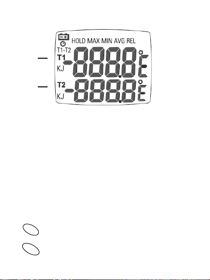
LCD DISPLAY
1
2
1. Primary LCD: Display T1 (1st thermocouple reading)
2. Secondary LCD: Display T2 (2nd thermocouple on differential or
intitial valve for relative mode.)
WARNING
1. Always connect thermocouple before turning the unit on
for most accurate readings
2. Make sure to plug sensor with correct polarity. Do not
be alarmed if erratic readings appear on display prior to
normal mode.
UNIT
HOLD
KEYPAD (CONTROLS)
Press “UNIT” to select ˚C/˚F.
Freeze display
2

Press “MODE” to change operation mode T1, T1-T2
MODE
or REL. The corresponding reading will display on the
primary LCD. The secondary LCD will always display T2
reading in differiential (DT222). It will display the initial
value when using “REL” mode.
PWR
Press and hold “PWR” to turn on the meter or
press it to turn off the meter. The meter will turn off
automatically after 60 minutes if you don’t press any
key. Press “HOLD” and “PWR” buttons to disable
Auto sleep mode. (see page 4)
Press “MAX/MIN” to change operation mode
MAX
MIN
from measured temperatue -> Max.-> Min.-> Avg. ->
back to live date. The corresponding value will display
on primary LCD. The corresponding value is calculated
since powered on or reset.
Press and hold to change thermocouple type.
SET
J-Type-Black Molded Connector
K-Type-Yellow Molded Connector
BKLT
Press to activate backlight
3

OPERATION
(1) POWER ON/ OFF
Note:
Make sure you have plugged in the thermocouple probe before
turning on. Press and hold PWR button to turn on the meter.
While the meter is on, press PWR button to turn off the meter.
(2) SLEEP MODE (AUTO POWER OFF)
The meter will turn off automatically after 60 minutes if no
buttons are pressed. To disable auto power off function, when
the meter is off, press and hold “HOLD” button then press
“PWR” button to turn on the meter, the primary LCD shows the
following. Sleep mode is now disabled.
(3) SET THERMOCOUPLE TYPE
Verify thermocouple type matches the probe being used.
K-type = Yellow molded plug
J-type = Black molded plug
Press and hold “SET” to switch type.
4

(4) TAKING MEASUREMENT
Make sure you have plugged in K or J type sensore probe on the
Connect thermocouple. If probe is open or not connected, the
top of the meter, if the probe is not plugged appropriate, LCD
LCD will show ”---”.
shows”---” on the display.
Verify thermocouple type is set correctly (see page 4)
Single input model shows T1, dual input model shows T1 and T2
Single Input: (DT221)
K
Dual Input: (DT222)
(5) CHANGE UNIT
Press UNIT button to change unit ˚C or ˚F. The meter default
temperature unit is ˚F. The meter will default to last selected
scale.
K
K
Press UNIT
K
K
5

(6) T1-T2/RELATIVE
Press MODE button to change operation, options include T1-T2
(DT222 only), T1-REL, T2-REL (DT222). The corresponding reading
will display on the primary and secondary LCD.
K
K
Press MODE
K
K
Press MODEPress MODE
T2 REL
T2 INITIAL
REL
K
K
Press MODE
K
K
REL
T1 REL
T1 INITIAL
Change Thermocouple Type: Press SET button for 2 seconds
to change thermocouple type K or J.
NOTE: Always verify proper selection of thermocouple type see page 3 “Set.”
K
K
K-TYPE (Yellow Plug) J-TYPE (Black Plug)
Press SET
for 2 seconds
6
J
J

(7) MAX/MIN/AVG
Make sure you have plugged in K or J type sensore probe on the
Press MAX/MIN button to change operation mode from live
top of the meter, if the probe is not plugged appropriate, LCD
data ->MAX -> MIN -> AVG -> back to live data. Corresponding
shows”---” on the display.
value will display on upper LCD. These values will reset at
power on or reset.
MAX
K
K
K
K
AVG
K
K
MIN
K
K
Reset MAX/MIN/AVG: Press Max/Min button for 2 seconds to
reset MAX/MIN/AVG analysis value. The MAX/MIN/AVG value
is updated to current reading.
(8) DATA HOLD
Make sure you have plugged in K or J type sensore probe on the
Freeze display of basic measurements or disable. Press HOLD
top of the meter, if the probe is not plugged appropriate, LCD
button again to go back to the temperature reading.
shows”---” on the display.
HOLD
K
K
7

(9) BACKLIGHT
Press BKLT to turn on the back light in any function. Back light
function will turn off automatically after 30 seconds.
SPECIFICATIONS
SPECIFICATION
TEMPERATURE UNIT
SENSOR INPUT
TEMPERATURE
RANGE
DISPLAY
RESOLUTION
ACCURACY
INPUT PROTECTION
TEMPERATURE
COEFFICIENT
SIZE
CE CERTIFICATE
The product complies with EMC directive 2004/108/EC
Technical standard: Emission EN 61326-1:2006 Class B
EN 55011:2009/A1:2010 Group 1 Class B
Immunity EN 61326-1:2006 EN 61000-4-2:2009
EN 61000-4-3:2006 A2:2010
DT221 DT222
˚C or ˚F Selectable
Single Input Dual Input
K-Type: -328˚F ~ 2498˚F (-200˚C ~ 1370˚C)
J-Type: -328˚F ~ 1922˚F (-200˚C ~ 1050˚C)
0.1˚C (0.1˚F)
±(0.2% + 1:4)˚F) ±(0.2% + 1˚C)
Maximum Voltage of Temperature input is 24DC or AC
0.01% of reading + 0.03˚C per ˚C
0.01% of reading + 0.06˚F per ˚F
When out of range 18˚C~28˚C (64F˚ ~ 82˚F)
159 x 55 x 38mm
(L x W x H)
8

TROUBLESHOOTING
E-1 Thermocouple 1 circuit error or over range
Thermocouple 2 circuit error or over range
E-2
E-3
Over/ under operation temperature
Hardware error
E-4
* LCD display “---” disconnected or open thermocouple.
BATTERY REPLACEMENT
WARNING
If the symbol “ “ appears on the LCD,
please replace the battery immediately
• Turn off the instrument
• Remove the battery compartment
• Change the battery
• Replace the compartment cover
END OF LIFE
CAUTION: This symbol indicates that
equipment and its accessories shall be
subject to a separate collection and correct
disposal.
9
,,,

Limited Warranty
The DT221 and DT222 are warranted to be free from defects in materials and
workmanship for a period of three years from the date of purchase. If within the
warranty period your instrument should become inoperative from such defects, the
unit will be repaired or replaced at UEi’s option. This warranty covers normal use
and does not cover damage which occurs in shipment or failure which results from
alteration, tampering, accident, misuse, abuse, neglect or improper maintenance.
Batteries and consequential damage resulting from failed batteries are not covered
by warranty.
Any implied warranties, including but not limited to implied warranties of
merchantability and fitness for a particular purpose, are limited to the express
warranty. UEi shall not be liable for loss of use of the instrument or other
incidental or consequential damages, expenses, or economic loss, or for any claim
or claims for such damage, expenses or economic loss. A purchase receipt or
other proof of original purchase date will be required before warranty repairs will
be rendered. Instruments out of warranty will be repaired (when repairable) for a
service charge. Return the unit postage paid and insured to:
• Accessories, probes and batteries ( Not Covered by Warranty)
• Claims are not acceptable for improper use ( including adaptation
to particular applications not foreseen in the instruction manual
or improper combination with imcompatible accessories or
equipment, or for repair carried out by unauthorized personnel.
1-800-547-5740 • FAX: (503) 643-6322
www.ueitest.com • Email: info@ueitest.com
This warranty gives you specific legal rights. You may also have other rights
which vary from state to state.
10
 Loading...