


INSTRUCTION MANUAL
DM383/DM410
1-800-547-5740 • Fax: (503) 643-6322 www.ueitest.com • email: info@ueitest.com
Introduction
The DM383 is an industrial duty digital multimeter that lets you keep your measurements in clear view. When your control panel doesn’t allow you to stay close to your meter, you can count on the extra large digital display to keep you informed.
Features include
•Designed to meet or exceed IEC348 and UL1244
•3 - 1/2 digit LCD display with 0.91” tall numera l s
•Data Hold
•Diode Test
•Rubber boot
•600 Volt fuse protection on all current ranges
•Continuity buzzer
•Auto polarity
•20µA range for measuring Flame Safeguard current (DM410 only)
Safety Notes
Before using this meter, read all safety information carefully. In this manual the word "WARNING" is used to indicate conditions or actions that may pose physical hazards to the user. The word "CAUTION" is used to indicate conditions or actions that may damage this instrument.
•Do not attempt to measure any voltage that exceeds the category based rating of this meter
•Do not attempt to use this meter if either the meter or the test leads have been damaged. Turn it in for repair at a qualified repair facility
•Ensure meter leads are fully seated by making a quick continuity check of the leads prior to making voltage measurements
•Keep your fingers away from the test lead’s metal probe
contacts when making measurements. Always grip the leads behind the finger guards molded into the probes
•Do not open the meter to replace batteries or fuses while the probes are connected
 WARNING!
Exceeding the specified limits of this meter is dangerous and can expose the user to serious or possibly fatal injury.
•Do not try to measure any voltage that exceeds 1000 V DC or 750 V AC
•Voltages above 25 volts AC or DC may constitute a serious shock hazard
•Turn off power, disconnect the battery, and discharge all capacitors before using the ! and diode functions
•Use a current clamp if measuring any current above 10 amps
•Always turn off power to a circuit (or assembly) under test before cutting, unsoldering, or breaking the current path - Even small amounts of current can be dangerous
•Always disconnect the live test lead before disconnecting the common test lead from a circuit
•In the event of electrical shock, ALWAYS bring the victim to the emergency room for evaluation, regardless of the victim’s
apparent recovery - Electrical shock can cause an unstable heart rhythm that may need medical attention
•Higher voltages and currents require greater awareness of physical safety hazards - Before connecting the test leads; turn off power to the circuit under test; set the meter to the desired function and range; connect the test leads to the meter first, then to the circuit under test. Reapply power
•If any of the following indications occur during testing, turn
off the power source to the circuit under test:
•Arcing
•Flame
•Smoke
•Extreme Heat
•Smell of Burning Materials
•Discoloration or Melting of Components
 CAUTION!
Do not attempt to remove the meter leads from the circuit under test. The leads, the meter, or the circuit under test may have degraded to the point that they no longer provide protection from the voltage and current applied. If any of these erroneous readings are observed, disconnect power immediately and recheck all settings and connections
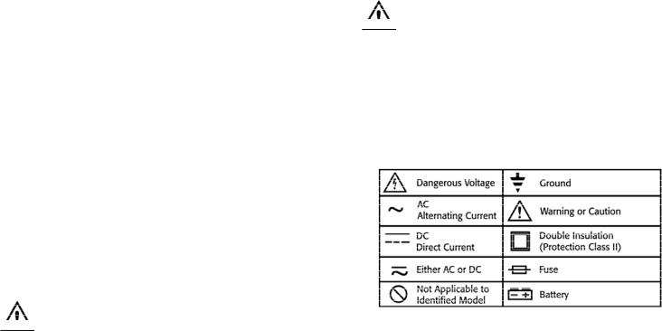
International Symbols
DM383/DM410-MAN |
P. 1 |
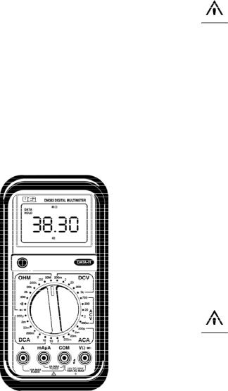
Controls, Indicators and Input Jacks
1.ON/OFF Push-button: Used to turn the power to the meter on or off.
2.Data Hold Push-button: Freezes the reading on the LCD for all functions and ranges.
3.“A” input jack: The red test lead is plugged into this jack for measuring current on the 10 AC or DC amp functions.
4.“mAµA” input jack: The red test lead is plugged into this jack for measuring mA or µA on either AC or DC current functions.
5.“COM” input jack: The black test lead is plugged into this jack for all measurements.
6.“V!” input jack: The red test lead is plugged into this jack for all ACV, DCV, OHM, Continuity Buzzer and Diode test functions and ra n g e s .
1 |
|
|
|
2 |
|
|
|
3 |
|
|
|
5 |
|
|
|
4 |
|
|
|
6 |
|
|
Operating Instructions
Measuring DC Volts
 WARNING!
To avoid the risk of electrical shock, instrument damage and/or equipment damage input voltage must not exceed 1000 volts DC.
Do not attempt to take any unknown voltage measurements that may be in excess of 1000 volts DC.
1.Set function and range switch to the desired DC V range. If you do not know the value of the voltage to be measured, always start with the highest range and reduce the setting as required to obtain a satisfactory reading.
2.Plug the red test lead into the “V/!” input jack and the black lead into the “COM” input jack of the instrument.
3.Disconnect the test leads to the circuit to be tested.
4.Connect the test leads to the circuit to be tested.
5.Reapply power to the circuit, the measured voltage will appear on the display of the instrument.
6.If the red test lead is connected to the negative (or lower voltage) side of the circuit, a minus sign will appear on the display, at
the left.
7.Disconnect power to the circuit before removing the test leads from the circuit.
Measuring AC Volts
 WARNING!
To avoid the risk of electrical shock, instrument damage and/or equipment damage input voltage must not exceed 750 volts AC.
Do not attempt to take any unknown voltage measurements that may be in excess of 750 volts AC.
1.Set function and range switch to the desired AC V range. If you do not know the value of the voltage to be measured, always start with the highest range and reduce the setting as required to obtain a satisfactory reading.
2.Plug the red test lead into the “V/!” input jack and the black lead into the “COM” input jack of the instrument.
3.Disconnect the test leads to the circuit to be tested.
4.Connect the test leads to the circuit to be tested.
5.Reapply power to the circuit, the measured voltage will appear on the display of the instrument.
6.Disconnect power to the circuit before removing the test leads from the circuit.
DM383/DM410-MAN |
P. 2 |
 Loading...