


INSTRUCTION MANUAL
DMEG2
1-800-547-5740 • Fax: (503) 643-6322 www.ueitest.com • email: info@ueitest.com
Introduction
The DMEG2 Insulation Resistance Tester is a completely portable, self-contained, four range, solid state test instrument.
Power is provided by eight internal, standard 1.5V, size AA (ABI) batteries. An electronically regulated constant voltage generator supplies the test voltage for the 2000M! range (1000V) and the 2000M! range (500V), and the 2000M! range (250V). The internal batteries supply the power directly for the 0-200! low resistance range.
This rugged precision instrument can locate intermittent shorts, defective electrical connections, insulation breakdowns or conductor failures due to the effects of temperature, moisture, abrasion, corrosion, or other environmental conditions.
One of the most effective applications, and one of the most overlooked applications for the DMEG2 is in the field of preventive maintenance. For example, when the insulation properties of a hermetic compressor motor begins to fail it usually does so gradually at first. A routine, periodic monitoring of the insulation resistance of the start and run winding will usually show evidence of a potential burn out well in advance of the actual occurrence.
Features include
•Battery operated
•Automatic circuit discharge
•Solid state circuitry
•LCD display
•Automatic zero adjust
•Four ranges
•Automatic low battery indication
•Audible warning signal
•Live circuit indicator
Safety Notes
Before using this instrument, read all safety information carefully. In this manual the word "WARNING" is used to indicate conditions or actions that may pose physical hazards to the user. The word "CAUTION" is used to indicate conditions or actions that may damage this instrument.
Electrical shock can cause an unstable heart rhythm that may need medical attention.
International Symbols
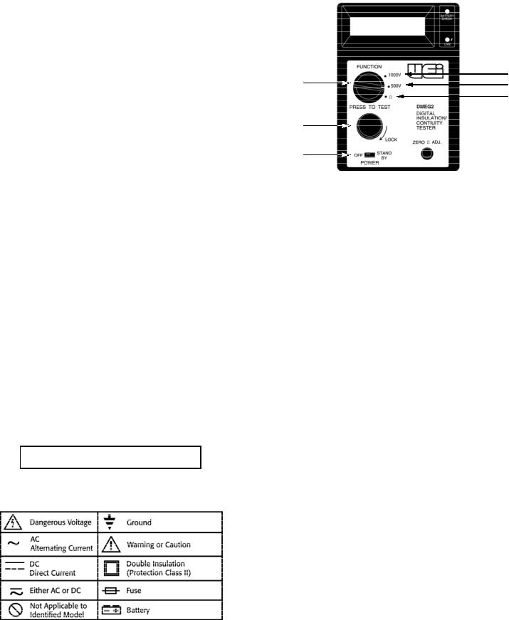
Controls and Indicators
4
1
3
2
6
5
1.Rotary Selector Knob: Switches measurement function.
2.Ohms: This is the low resistance or “continuity” position. Used to identifylow resistance circuits such as motor run and start winding which may differ by only a few ohms.
3.200M! (250, 500V): In this position approximately 500 V DC is applied to the circuit under test when the TEST switch is pressed. The 0 - 20 0 M! range is used primarily to test insulation resistances which have begun to degra d e .
4.200M! (1000V): In this postilion approximately 1000 V DC is applied to the circuit under test when the TEST switch is
pressed. This is the range which is normally used for preventive maintenance measurements on electrical equipment. Insulation resistance values in this application typically exceed 100M!.
5.ON/OFF switch: Slide the switch forward to turn the instrument on, slide it back to turn the instrument off.
6.Test Switch: The TEST switch is normally OFF, spring loaded, momentary action switch which “turns on” the DMEG2. The momentary action is a safety feature. The test voltage generated by the DMEG2 is automatically discharged when the TEST switch is released.
DMEG2-MAN |
P. 1 |
Operating Instructions
 CAUTION!
Observe all safety precautions when the CONTROL switch is set to either the 2000M! (500V) or the 2000M! (1000V) position. Connect the DMEG2 test leads to the circuit under test before operating the TEST switch. DO NOT touch the battery clip ends of the test leads when the TEST switch is in the TEST position. Some electrical equipment, especially cables, may retain an electrical charge when disconnected from the line. It is a good practice to discharge such equipment with grounding straps, or other suitable devices, before touching or making
connections. The DMEG2 automatically discharges the test circuits when the spring loaded TEST switch is released.
 WARNING!
Remove all power to the circuit under test when making resistance measurements. If any voltage is present in the test circuit an erroneous reading will result.
Motors and Generators
Disconnect the motor from the line either by opening the main switch or by disconnecting the wires at the motor terminals. if the main switch is opened and measurements are made at the switch contacts, then the insulation resistance of all components between switch and motor will be measured simultaneously. If a fault is indicated it will be necessary to test each section separately.
AC Devices
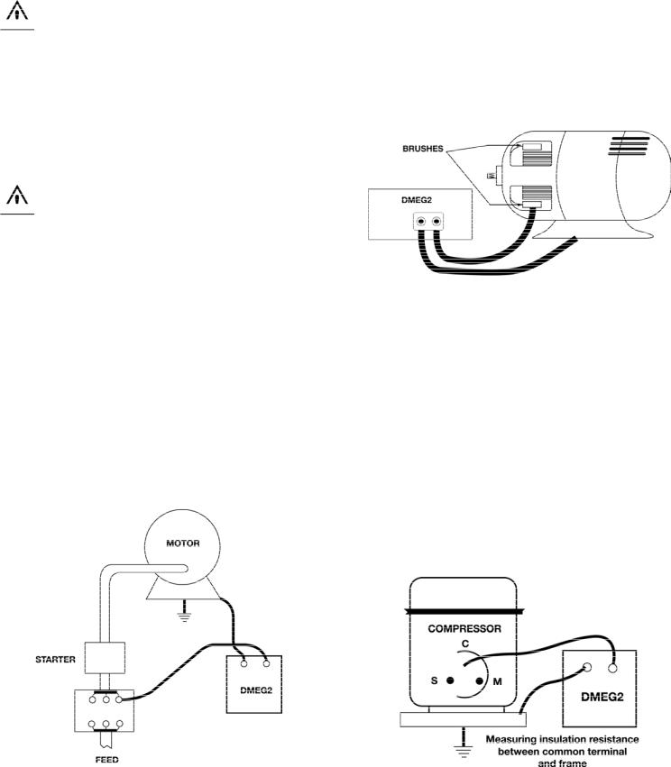
The basic test is to connect the red test lead of the DMEG2 to one of the motor terminals, or wire, and the black test lead to the frame or housing (Fig. 1). Start and run winding may be checked for correct resistance by setting the SELECTOR switch to OHMS and connecting one test lead to the common winding terminal and the other test lead to the start or run terminal.
DC Devices
Independent insulation tests may be carried out between the electrical sections of a DC generator, or motor, and ground. Separate the brushes from the commutator (Fig. 2) to isolate the brushes and field coil functions from the rotor. These separated sections may be easily tested independently of each other. This does not apply, however, when an overall insulation test is intended. In this case the brushes remain in contact with the commutator so that the three sections (brushes, coils and rotor) may be tested integrally.
(Fig 2)
Hermetic Compressor
Most hermetic compressor utilize a three terminal block for making electrical connections to the sealed unit (Fig. 3). The connection may be made by an “umbilical” cord or a screw terminal, but the most common connection method is usually with a relay that pushes onto the S and M terminals and an overload protector that pushes onto the C terminal. (Refer to the manufacturer’s manual)
Shut off power to the unit under test and remove the connections to the compressor terminal block. Connect the red test lead of the DMEG2 tot he C terminal and the black test lead to the frame, or ground. Measure the insulation resistance. Low values of insulation resistance may indicate the presence of contaminated refrigerant. Refer to the chapter on interpreting test results.
Winding continuity may be checked by setting the SELECTOR switch on OHMS. Check the start and run winding by measuring the resistance between the C terminal and the S or M terminal.
(Fig 1)
(Fig 3)
DMEG2-MAN |
P. 2 |
 Loading...