

Page 1
1-800-547-5740 • Fax: (503) 643-6322
www.ueitest.com • email: [email protected]
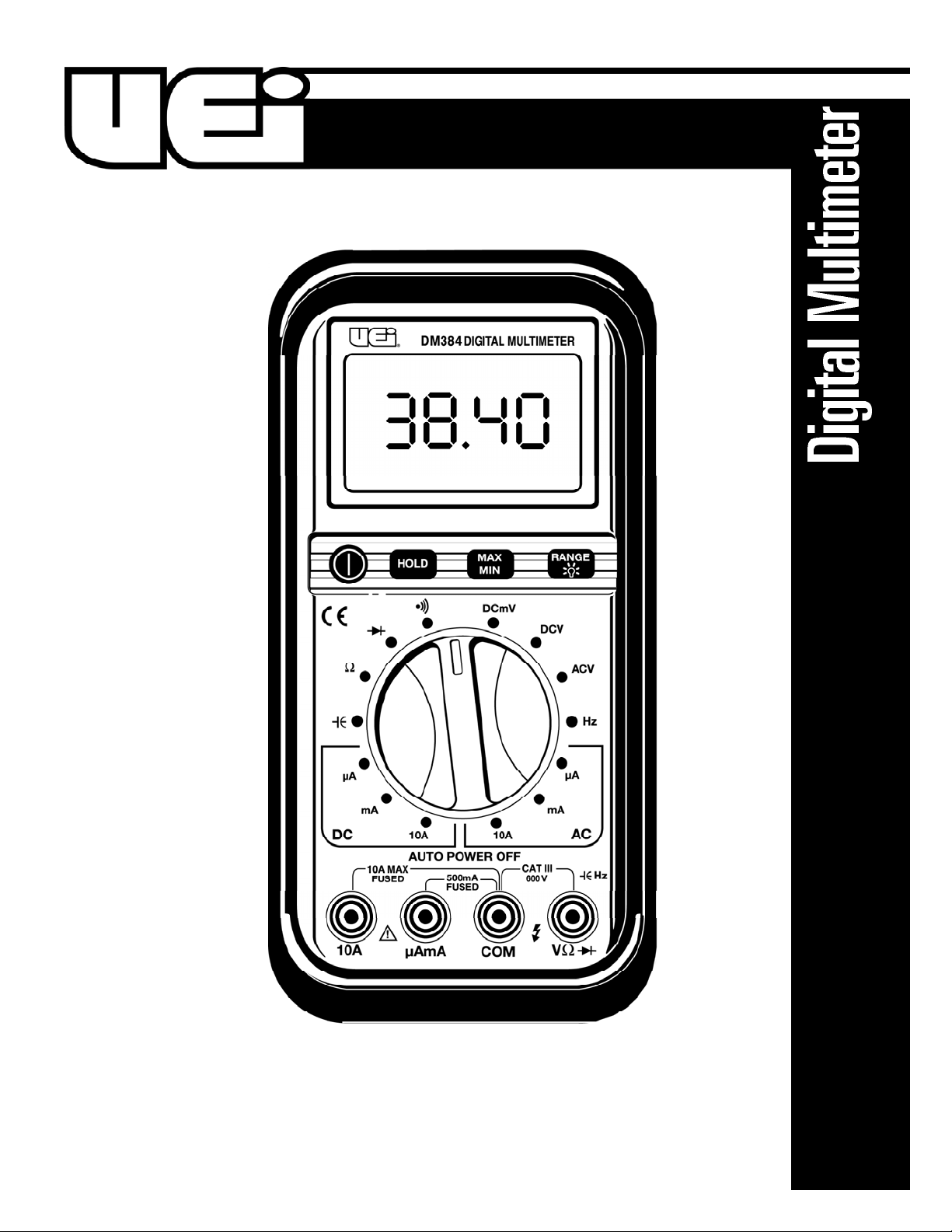
DM384
INSTRUCTION MANUAL
Page 2
Introduction
The DM384 gives you advanced troubleshooting technology for
challenging tasks. It has numerous high-end features like MIN / M A X
capture for unattended measurement monitoring, capacitance for
checking run/start capacitors, and frequency for quick verification of
g e n e rators, inverters, and control circuit operation. The large LCD display
has an electro luminescent backlight for easy viewing at a distance.
The DM384’s combination of dura b i l i ty, visibility, and functionality are
s p e c i f i cally tailored to meet the expanding needs of today’s HVAC/R
technicians, plant maintenance professionals, appliance technicians, and
electrician's. The DM384 is handheld, and battery powered. It is designed
and tested to IEC 1010-1 (EN 61010-1) standards, the EMC directive and
other safety standards. It is rated to measure up to 1000 volts in a CAT- II
environment and up to 600 volts AC and DC in a CAT- I II environment.
Features include
• 750 volts AC and 1000 Volts DC
• 10 Amps AC and DC
• .01 µA DC resolution for flame safeguard circuit testing
• Frequency to 40 MHz
• Capacitance to 40,000 microfarad
• Resistance to 40 Megohms
• Analog bar graph
• Continuity
• Diode check function
• Autoranging
• Large backlit LCD display
• Low battery indicator
Safety Notes
Before using this meter, read all safety information carefully. In
this manual the word "WARNING" is used to indicate conditions
or actions that may pose physical hazards to the user. The word
"CAUTION" is used to indicate conditions or actions that may
damage this instrument.
• Do not attempt to measure any voltage that exceeds the
ca t e g o ry b ased rating of this meter
• Do not attempt to use this meter if either the meter or the test
leads have been damaged. Turn it in for repair at a qualified
repair facility
• Ensure meter leads are fully seated by making a quick continuity
check of the leads prior to making voltage measurements
• Keep your fingers away from the test lead’s metal probe
contacts when making measurements. Always grip the leads behind
the finger guards molded into the probes
• Use a current clamp adapter when measuring current that may
exceed 10 amps. See the accessories in UEi’s full-line ca t a l o g
• Do not open the meter to replace batteries or fuses while the
probes are connected
WARNING!
Exceeding the specified limits of this meter is dangerous and can
expose the user to serious or possibly fatal injury.
• Voltages above 60 volts DC or 25 volts AC may constitute a
serious shock hazard
• Always turn off power to a circuit (or assembly) under test
before cutting, unsoldering, or breaking the current path Even small amounts of current can be dangerous
• Always disconnect the live test lead before disconnecting the
common test lead from a circuit
• In the event of electrical shock, ALWAYS bring the victim to
the emergency room for evaluation, regardless of the victim’s
apparent recovery - Electrical shock can cause an unstable heart
rhythm that may need medical attention
• Higher voltages and currents require greater awareness of
physical safety hazards - Before connecting the test leads; turn
off power to the circuit under test; set the meter to the desired
function and range; connect the test leads to the meter first, then
to the circuit under test. Reapply power
• If any of the following indications occur during testing, turn
off the power source to the circuit under test:
• Arcing
• Flame
• Smoke
• Extreme Heat
• Smell of Burning Materials
• Discoloration or Melting of Components
CAUTION!
Do not attempt to re m ove the meter leads from the circuit under test.
The leads, the meter, or the circuit under test may have degraded to
the point that they no longer provide protection from the voltage and
c u r ren t applied. If any of these erroneous re a d i n gs are observed,
disconnect power immediately and recheck all settings and connections.
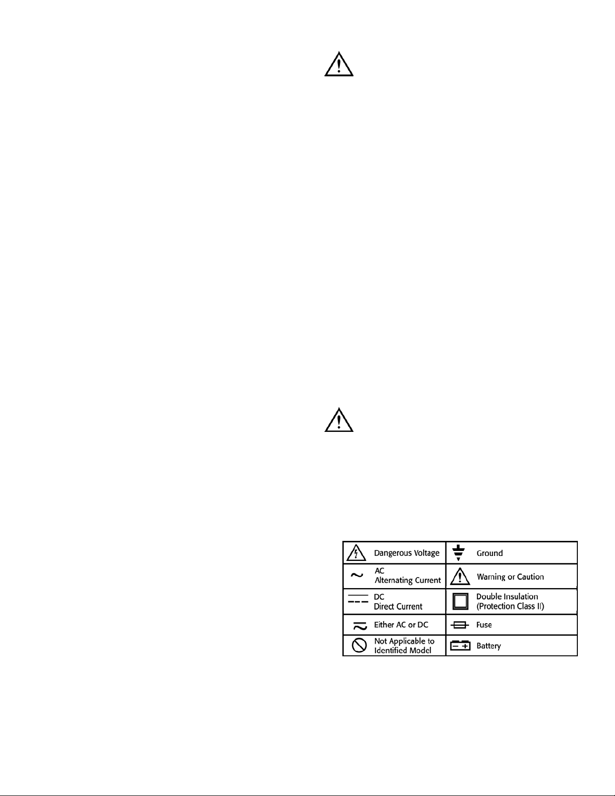
International Symbols
DM384-MAN P. 1
Page 3
LCD Display Functional Description
1. The main numerical display indicates measured numerical values.
2. The Auto Power Off icon indicates that the sleep mode function
is active.
3. The DC icon indicates the meter is reading DC voltage or current.
4. Indicates a negative polarity measurement. (Applicable to
DC functions).
5. Indicates the meter is reading AC voltage or current.
6. The Low Battery icon indicates the battery is low and must be
changed immediately.
7. The HOLD icon indicates that the “HOLD” button has been
pressed and the display is no longer updating numerical data.
8. The Autoranging icon indicates that the meter is in the
autoranging mode and will automatically select the range that
offers the best resolution for the signal being measured.
9. The MAX icon indicates that the “MIN/MAX” button has been
pressed (once) and the meter is displaying the maximum value
reached, from the time the record mode was selected.
10. The MIN icon indicates that the “MIN/MAX” button has been
pressed (a second time) and the meter is displaying the minimum
value reached, from the time the record mode was selected.
NOTE: If both MIN and MAX are displayed and flashing, then
recording is active while real-time measurements are displayed.
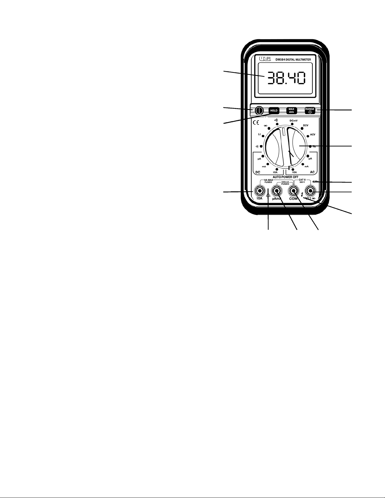
C o n t rols and Indicators
1. Digital Display: Readings are displayed on a digital, 4000
count display, along with the appropriate polarity indication and
range and function enunciators (icons). The decimal point moves
a u t o m a t i cal ly in the autoranging mode and remains in place when
recording or when the range is manually selected.
2. Power Push-button: Used to turn the power to the meter on
or off.
3. MIN/MAX Push-button: Causes the meter to record and display
the maximum or minimum value of any function selected. The word
“ M IN” or “MAX” appears in the upper right of the LCD. This feature
resets when the selector is moved or the meter is cycled off.
4. Hold Push-button: Freezes the reading presently on the digital
display, and displays the words “ DATA HOL D ” on the left side of
the LCD. To cancel data hold, press the “ DATA HOL D ” b u t t o n
again. This feature resets only when the push-button is pressed a
second time, not when the selector is moved.
5. Range and Backlight Push-button: Press briefly until a single
beep is heard (less than one second) to lock the meter in a range
or to step through ranges. To turn on or off the backlight, press
and hold for two seconds (illuminates shortly after the second beep
is heard).
6. Rotary Switch: A l l ows you to switch between any of the
functions or values indicated by the numbers, icons, and group
outlines printed around the rotating dial.
7. 10 Amp, Fused, Meter Lead Terminal: Use this input
terminal (port) when measuring amps greater than 400 mA,
but less than 10 Amps AC or DC. Use caution when selecting
a m p e r age measurements on the rotary dial. Remember
a m p e r age measurements are made in series with your circuit.
8. This Symbol Reminds the User to Follow Provided
Instructions: See “Caution” in the international symbol section
of this manual.
9. Microamp/Milliamp Input Terminal: The red test lead is
plugged into this terminal when measuring current (AC or DC)
in the 400 mA and below ra n g e .
10. Common Terminal: The black test lead is plugged into this
terminal, and supplies the ground or “low” reference for all
m e a s u r e m e n t s .
11. "Flash" Symbol: Warns operators that potentially dangerous
voltages may be present. Use caution when making
high-voltage measurements.
12. Multifunctional (Volts, Ohms, and Diode Test) Input
Terminal: Use the red test lead in this terminal for any of these
test functions.
13. Multifunctional Terminal Information: I n d i cates the
m aximum input values and ca t e g o ry r atings established
by IEC 1010 - 1 .
4
1
2
12
3
6
10
5
11
987
DM384-MAN P. 2
Page 4
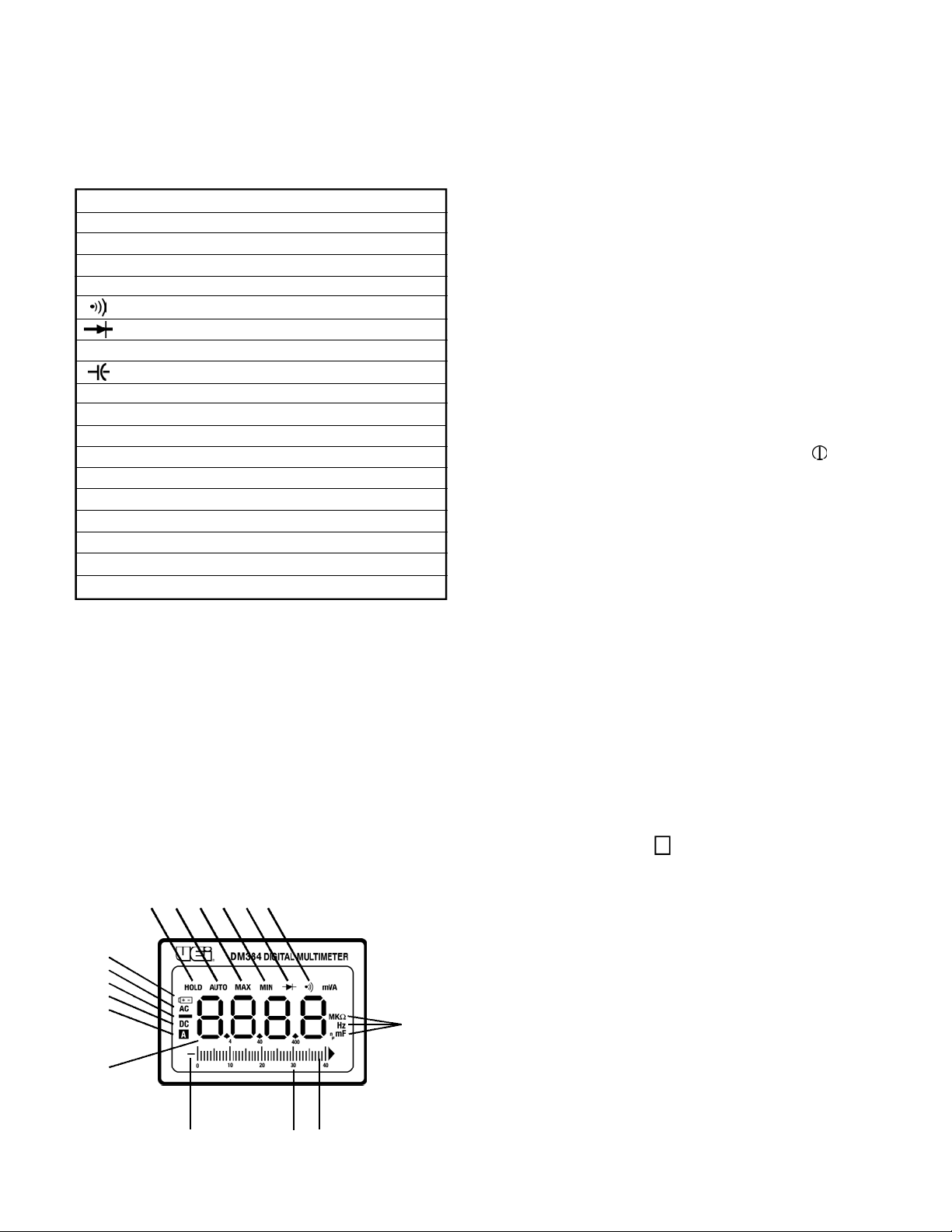
11. The Diode Symbol indicates that diode testing has been selected.
12.The Audible Continuity icon indicates that the continuity mode
has been selected.
13.The following symbols represent the type and value of
measurement being made:
NOTE: When “OL” is displayed, it indicates the value measured
exceeds the limits of the selected range, or exceeds the over-all
limits of the meter.
14.The Analog Bar-graph provides a fast responding (updates 20
times per second) volumetric indication of the input value. This
feature is designed to react like the analog display of a
needle-movement meter.
15.The Range Indicators identify the maximum value that can be
displayed, either numerically or by the bar-graph, in the presently
selected range.
16.The Negative-polarity indicator for the analog bar-graph appears
when the meter is reading a negative DC voltage or current.
DM384-MAN P. 3
Operating Instructions
Functional Description
The DM384 is designed to make basic electrical measurements quickly
and easily. Its autoranging functions are augmented by range and
function information that appears on the LCD display. Its extra large,
backlit numerical display is designed to be monitored from a distance,
while its fast responding analog bar-graph allows you to monitor rapidly
or constantly changing input signals.
This is a 4000 count, autoranging digital multimeter that employs high
input impedance (equal to or greater than 10 MΩ) to ensure accurate
measurement readings and circuit isolation for digital and analog
devices. The auto ranging feature can be over-ridden to allow manual
range selection. Minimum and maximum input values can be recorded
at the operator’s option. The input ports use standard four-millimeter
insulated-plug test leads (provided). Maximum measurement values are
1000 Volts (CAT II) or 600 V AC/DC (CAT III) and 10 amps AC or DC.
Meter Power
The DM384 is powered on and off using the push-button on the far left,
which is marked with the international on/off symbol ( ).
This instrument will automatically enter a sleep mode (commonly
referred to as “auto power-off”) when left on for more than 30 minutes
with no activity. To identify that the auto power-off function is active, an
icon appears (an “A” within a box) on the left side of the display along
with other on-screen information. Immediately prior to automatica l l y
shutting off, three sets of two beeps will sound at approximately
five-second intervals. After five more seconds, a final long duration
tone will sound as the display goes blank. If you do not want the meter
to turn off at this time, press the “RA NG/BACKL I GHT” push-button
before the final tone sounds to reset the 30-minute time-out counter.
When the auto power-off function takes effect the last value measured
is stored, allowing you to review that measurement upon reactivating
the meter. Press one of the three function buttons (other than power) to
reactivate the meter. The “HOLD” icon and the last measurement will
be displayed.
To disable the auto power-off function, allowing constant monitoring
or recording, press and hold down the “MIN/MAX” or
“RA NG/BACKL I GHT“ button while initially turning on the meter.
The auto power-off icon “ “ will no longer be visible.
NOTE: The sleep mode only reduces battery drain. Do not store your
meter without verifying that power is turned off at the switch.
Symbol Function or Value
Hz Hertz (frequency in cycles per second
ACV Volts AC
DCV Volts DC
DCmV Millivolts DC
Ohms and Audible Continuity
Diode Test Voltage Drop
Ω Ohms (resistance value)
Capacitance (in farads)
DC Direct Current (or voltage)
AC Alternating Current (or voltage)
µA Micro amps
mA Milliamps
10A Amps
M 1 Meg = 1,000,000 or (1 x 10⁶)
K 1 Kilo = 1,000 or (1 x 10³)
m 1 Milli = 0.001 or (1 x 10⁻³)
µ 1 Micro = 0.000001 or (1 x 10⁻⁶)
n 1 Nano = 0.000000001 or (1 x 10⁻⁹)
7
8
14
6
A
9 10 11 12
13
1516
5
4
3
2
1
Page 5

Selecting the Proper Test Lead Ports
The test leads must be plugged into the proper ports to make electrical
measurements. Press the test lead plugs firmly into the meter ports to
ensure they are fully seated.
The black test lead will be plugged into:
• COM: For all measurements
The red test lead will be plugged into:
• VΩHz : For testing volts AC or DC, ohms, continuity,
diodes, capacitance and frequency
• µA mA: For testing amps AC or DC with values below
400 milliamps
• 10A: For testing amps AC or DC with values up to
(not exceeding) 10 amps
Hold
The HOLD push-button freezes the numerical data displayed on the
LCD at the moment it is pressed. To engage data hold, press the HOLD
push-button, located on the right side on the face of the instrument.
When this function is active, the word “HOLD” appears on the left side
of the digital display. To cancel data hold, press the HOLD button
again. The numerical value will remain displayed even if the rotary
dial is moved from its original position.
MIN/MAX Recording
Recording is initiated when the “MIN/MAX” push-button is pressed.
This feature allows the meter to display the highest and lowest
numerical value obtained in the selected measurement function. you
may prefer to manually select your range as the autorange feature is
automatically overridden at the moment the button is pressed and the
meter locks into whatever range is active.
When this feature is active you can cycle through your display options
by briefly pressing the “MIN/MAX” push-button. As you cycle through
the options, one of the following will appear on the screen:
• MAX: When displaying the maximum recorded value
• MIN: When displaying the minimum recorded value
• MIN - MAX (flashing): When displaying real-time measurements
while recording
Cycling through these options will not affect the data stored in memory.
Note: If the auto power-off function activates during recording, the
stored “MIN/ MAX” information is retained when the meter is
reactivated, however, recording does not continue while it is in the
sleep mode.
To cancel recording, press the “MIN/MAX” push-button for
approximately one full second, or select another range or function
using the range button or rotary dial.
Range Selection
This meter is autoranging by default but can be set to any available
range that the user desires. To manually select a range briefly press the
“RA NG/BACKL I GHT” push-button . The autoranging icon “A UTO”
will disappear from the screen and the range will be locked into that
which was last in use. To change ranges, repeatedly press the button to
cycle to the desired range (displayed on the small numerical range
i n d i cat or below the measured value indica t o r s ) .
To return to autoranging press and hold the “RA NG/BACKL I GHT”
push-button for approximately one full second.
Backlight
This meter uses an electro luminescent (E.L.) backlight to provide easy
to read data in low light areas. Although E.L. lighting consumes less
energy than incandescent backlighting, it is still one of the major
sources of battery drain in your meter. For longer battery life, use it only
as necessary.
To turn the backlight on and off, press and hold down the
“RA NG/BACKL I GHT” push-button until its blue glow appears of
disappears as desired. Two beeps will be heard (relating to the
“RA NGE” function) prior to the light coming on.
Note: The backlight cycles on or off approximately 1/2 second after the
tone sounds its second beep.
Rotary Switch
The rotary switch is used to select the measurement function and in
some cases, range. Once a function has been selected, the meter
will automatically seek the range (autoranging) that offers the best
resolution for the incoming signal. This eliminates the need for
numerous switch positions and keeps your measurements fast and
easy. However, there are multiple switch positions provided for some
functions to separate the ranges into groups that will take advantage
of circuit technology that offers superior accuracy.
While this meter is manufactured with a number of built in fail-safes,
the potential to damage the meter, blow a fuse, or cause damage to a
circuit under test due to improper use does exist. Set the rotary function
select switch to the appropriate setting before connecting test leads, or
applying power to circuits under test. Also be sure the test leads are in
the proper jacks for the function you have selected.
Measuring Capacitance
This meter measures capacitors, such as those used as motor-run-start
capacitors, and electronic control card circuitry, ranging in value from
.001 nanofarad to 40,000 microfarads (µf).
WARNING!
Capacitors should be completely discharged prior to testing. Some
electronic devices use capacitors in circuits that are designed to
increase voltage. Be design, a capacitor stores energy. If a capacitor
has been charged at greater than 600 volts, attempting to measure
it may damage your meter. Larger capacitors may store enough
energy to cause injury if they are discharged through the body. Use
a conductive device to dissipate the charge on capacitors. Large
capacitors should be “bled” by using a resistive load between terminals
to slowly eliminate the charge. Smaller capacitors may be directly
shorted using a metallic object.
DM384-MAN P. 4
Page 6

To make capacitance measurements, plug in the test leads as
instructed, then:
1. Discharge the capacitor to be tested as prescribed above.
2. Isolate the capacitor by lifting at least one of its two legs away
from the circuit.
3. Select the capacitance position “ “ on the rotary
function switch.
4. Connect the red test lead to one side of the capacitor, and the
black to the other.
5. Read the measured value.
Note: In the autora n ging mode, it takes approximately 10 seconds to
settle on a value for a capacitor. La rger capacitors re q u i re even more
time. In the manual ra n ging mode, measurements are often faster.
Measuring Resistance
Resistance is the measure of a component’s or circuit’s tendency to
oppose current flow. Because of the many factors that affect resistance,
the most accurate measurements are made when components under
test are isolated from other components or circuits. It is critical to the
accuracy of the measurement that you remove all power to the circuit
when making resistance measurements. If the component or circuit
cannot be isolated, turn off all power sources and discharge all in-circuit
capacitors before attempting the measurement. This meter may be
damaged if more than 600 volts are present.
Note: When measuring critically low ohm values, touch the tips of the
test leads together and record the reading. Subtract this value from the
total resistance of the circuit under test to obtain the actual value.
For resistance measurements above one Megohm the display might take
a few seconds to stabilize. This is normal for high resistance readings.
The voltage or current applied during resistance measurements
could damage some extremely sensitive electronic devices. Typically,
the voltages present at the test leads when making resistance
measurements range from 3 volts at 1.5 mA (in the lowest range)
to .5 volts at <1µA (in the highest range).
To measure the voltage drop on diodes, plug in the test leads as
instructed, then:
1. Turn off the meter.
2. Select the diode test function on the rotary function switch.
3. Connect the red test lead to the anode side of the diode, and the
black to the ca t h o d e .
Note: T h e r e is normally a printed black band around the cathode of
a standard diode.
4. Note the displayed value.
5. Reverse the red and black test leads. Again, note the displayed value.
6. If the digital reading in the first (forward biased) direction indicates
some measurable value and the reading in the reverse biased
direction shows an over-range “.OL” the diode is probably good.
7. If the displayed value is low, or all zeros, in both directions, the
diode id probably shorted.
8. If the display indicated an overload “.OL” in both directions, the
diode is probably open (burned out).
Note: Some diodes, such as those used in microwave ovens, require a
higher biasing voltage than this meter supplies. See UEi’s catalog for an
economical high-power diode test lead adapter set if necessary.
Measuring Continuity
Continuity is the measure of a circuit or component’s ability to conduct
electricity. Use this mode to make quick checks for continuity (good
connections) in electrical circuits, such as wiring, speaker cables,
switches, or relays. In the continuity mode an audible tone sounds when
the value measured is approximately 30Ω or less. The resistance of the
circuit (up to 400 ohms) is displayed regardless of the continuity tone.
To measure continuity plug in the test leads as instructed, then:
1. Turn off the meter.
2. Select the continuity “ “ test function on the rotary
function switch.
3. Place one probe to each side of the circuit to be tested. If the circuit
measures approximately 30Ω or less, the meter will sound a
continuous tone.
Measuring DC Voltage
WARNING!
To avoid the risk of electrical shock and instrument damage, input
voltages must not exceed the limits specified for the installation
category you are working in. DO NOT attempt to take any unknown
voltage measurements that may exceed these values.
Note: When taking voltage measurements your meter must be
connected in parallel to the circuit, or circuit element, under test.
To measure DC volts plug in the test leads as instructed, then:
1. Turn off the meter.
2. Select the “DC V” or “DC m V ” function on the rotary function switch.
• The DCV position can be used for any DC voltage
measurement
• The DCmV position is ideal for DMM accessories that have a
DC millivolt output
• If you do not know the maximum value of the voltage to be
measured, use the DCV position and allow the meter
to auto-range.
3. Connect the test leads across the test-points of the circuit to be tested.
4. Read the measured voltage on the display.
Note: If the voltage on the red test lead is lower (more negative)
than that on the clack test lead, the negative polarity symbol (a
minus) will appear on the left of the display.
DM384-MAN P. 5
Page 7

Measuring AC Voltage
WARNING!
To avoid the risk of electrical shock and instrument damage, input
voltages must not exceed the limits specified for the installation
category you are working in. DO NOT attempt to take any unknown
voltage measurements that may exceed these values.
Note: When taking voltage measurements your meter must be
connected in parallel to the circuit element, under test.
To measure AC volts plug in the test leads as instructed, then:
1. Turn off the meter.
2. Select the AC volt “ACV” position on the rotary function switch.
• If you do not know the maximum value of the voltage to be
measured, (within this meter’s category specific rating) allow
the meter to auto-range
3. Connect the test leads across the test-points of the circuit to be tested.
4. Read the measured voltage on the display.
Measuring Hertz (Frequency - Hz)
Use the Hertz function to determine the frequency of main power,
generators, inverters and electronic circuits. Different terms are used to
describe Hertz. Some of these are:
• Frequency of oscillation / Frequency / freq.
• Cycles per second / Cycles / CPS
• Hz
Note: When measuring frequency your meter must be connected in
parallel to the circuit, or circuit element, under test.
To measure frequency, plug in the test leads as instructed, then:
1. Turn on the multimeter.
2. Select the “Hz” position on the rotary function switch.
3. Connect the test leads across the circuit to be tested.
4. Read the measured frequency on the display.
Measuring Amps
Current flow is measured in amperes or “amps”, which indicates the
volume of electrons that pass through a given point. When taking
current measurements, this meter must be connected in series with
the circuit (or circuit element) under test.
CAUTION!
Never connect the test leads across (in parallel with) a voltage source
when attempting to measure current. This can cause damage to the
circuit under test or this meter.
Note: To measure current, you must create a break in the circuit under
test and make the meter part of the circuit. Two connection points are
created when a circuit is broken. On one side is the power source and
the other is the load.
To measure AC or DC current flow, (in amps), insert the test leads into
the meter as instructed, then:
1. Ensure power is off to the circuit to be tested.
2. Turn the meter on.
3. Select the AC or DC amp position on the rotary function switch.
4. Break the circuit as described earlier and connect the meter leads
to the points created by the break.
5. Apply power to the circuit.
6. Read your measurement value.
Note: When performing flame safeguard testing (a low DC amperage
test) on some gas furnace models, an adapter (sold by UEi) can be
placed in-line with the flame sensor to make testing fast and easy.
Note: When measuring DC current, A minus sign will be displayed if
the current is flowing opposite to the connection polarity.
Note: As a safety discipline, disconnect power to the circuit under test
before removing either test lead.
M a i n t e n a n c e
Periodic Service
WARNING!
Repair and service of this instrument is to be performed by qualified
personnel only. Improper repair or service could result in physical
degradation of the meter. This could alter the protection from
electrical shock and personal injury this meter provides to the
operator. Perform only those maintenance tasks that you are
qualified to do.
These guidelines will help you attain long and reliable service from
your meter:
• Calibrate your meter annually to ensure it meets original
performance specifications
• Keep your meter dry. If it gets wet, wipe dry immediately.
Liquids can degrade electronic circuits
• Whenever practical, keep the meter away from dust and
dirt that can cause premature wear
• Although your meter is built to withstand the rigors of daily
use, it can be damaged by severe impacts. Use reasonable
caution when using and storing the meter
Cleaning
Periodically clean your meter’s case using a damp cloth. DO NOT use
abrasive, flammable liquids, cleaning solvents, or strong detergents as
they may damage the finish, impair safety, or affect the reliability of the
structural components.
DM384-MAN P. 6
Page 8
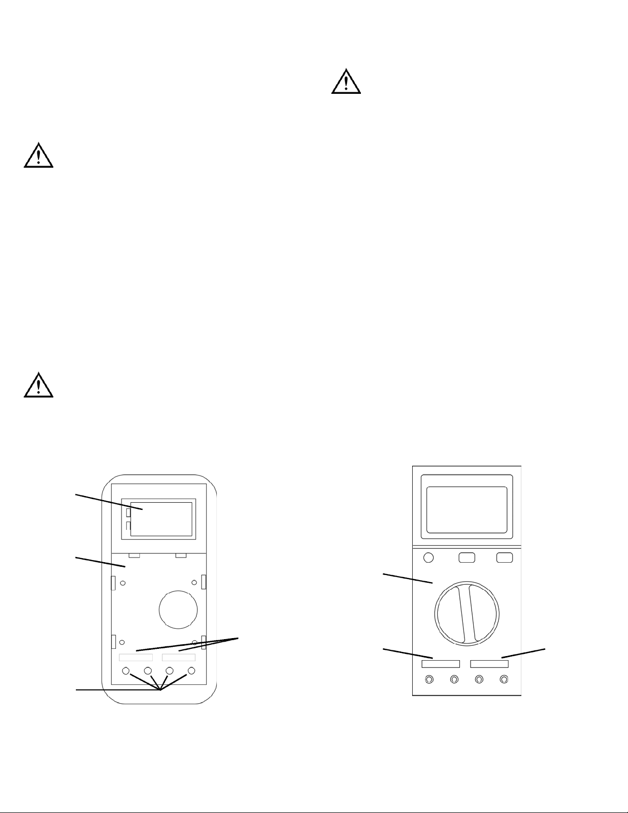
Battery Replacement
Always use a fresh replacement battery of the specified size and type.
Immediately remove the old or weak battery from the meter and
dispose of it in accordance with your local disposal regulations. Batteries
can leak chemicals that corrode electronic circuits. If your meter is not
going to be used for a month or more, remove and store the battery in
a place that will not allow leakage to damage other materials.
WARNING!
Disconnect the test leads from the circuit under test and from the meter
prior to removing or installing batteries.
To install a new battery, follow these procedures:
1. Turn off the meter.
2. Remove the rubber boot from the meter, starting at the top.
3. Place meter face down on a clean cloth.
4. Remove the screws from the rear case. Two machined screws
fasten the bottom and two self-tapping screws fasten the top.
5. Separate the two halves to expose the battery.
6. Remove and discard the old battery. Always dispose of old batteries
promptly in a manner with local disposal regulations.
WARNING!
Under no circumstances should you expose batteries to extreme heat or
fire as they may expose and cause injury.
7. Place a fresh 9V battery in the battery clip.
8. Reassemble the meter.
View of meter face down with back cover off.
1. B a t t e ry 2. P CB
3. Test lead ports 4. Fuses, under PCB
Fuse Replacement
WARNING!
Disconnect the test leads from the circuit under test and from the meter
prior to removing or installing fuses! Replace the bottom fuse with the
fuse specified for this meter ONLY!
To replace a blown fuse, perform the following procedures:
1. Turn off the meter.
2. Remove the rubber boot from the meter, starting at the top.
3. Place meter face down on a clean cloth.
4. Remove the screws from the rear case. Two machined screws
fasten the bottom and two self-tapping screws fasten the top.
5. Separate the two halves.
6. Lift the entire printed circuit board (PCB) housing up and away from
the front half of the meter. Lift the PCB housing straight up as there
are metal cylinders inside the test lead insulators that must slide
out with it.
7. Turn the housing over to expose the fuses.
8. Check to ensure the fuse is bad by confirming that there is no
c o n t i n u i ty b etween the metal ca p s .
Note: If the fuse is good, check for corrosion at the fuse clips and
ensure clips are tight around the fuse.
9. Insert a new fuse, or reinsert the good one.
10. Reassemble the meter.
View of PCB housing face-up with cover off.
1. P CB 2. 12A, 250V Fu s e
3. 0.5A, 660V Fu s e
DM384-MAN P. 7
1
2 3
1
2
4
2
Page 9
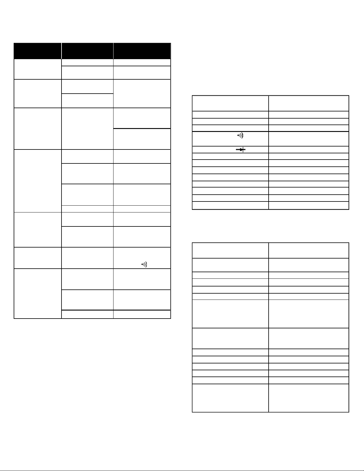
Tro u b l e s h o o t i n g
This unit contains no user serviceable parts beyond those listed in the
table. In the event your instrument is physically damaged or does not
function properly after taking the listed action, please return the
instrument to UEi following the warranty and service instructions.
S p e c i f i c a t i o n s
Measurement limits
Note: When servicing the meter, use only the replaceable
parts specified.
Physical Specifications
DM384-MAN P. 8
If I See This
Malfunction
Instrument does not
turn on
Instrument turns on
but LCD indicates
some unreasonable or
unchanging value
A value appears on
screen with no input
applied
A known value is not
displayed on the LCD
when measured
Meter reading
is unstable
No audible tone
with near zero
resistance value
Amps readings do
not work
I Should
Check For
Battery voltage
On/Off switch
position
MAX button pressed
HOLD button pressed
Stray voltage
MAX and HOLD
buttons pressed
Bad test lead connections
Defective test leads
Battery voltage
Offset rotary
selector knob
Bad test lead contacts
Improper selector position
Proper switch position
Proper test lead
port position
Blown fuse
Then Take This
Corrective Action
Replace low battery
Ensure button moves freely
and is in the on position
Look for MAX HOLD icons
displayed on the LCD
-Turn off one or
both buttons
Short test leads together -
If a value near 000 appears,
instrument is OK
Move meter and leads away
from devices that create
electrical fields
Turn off one or both buttons
(check for icons on LCD)
Ensure test leads are fully
inserted and free of
corrosion or dirt
Short test leads together in
the 400 ohm scale - Expect
less than .5Ω
Replace low battery
Ensure knob is firmly placed
in switch position
Ensure there is no insulating
material, dirt or debris at
contact points
Tone sounds only in
continuity mode. Place
selector in position
Ensure switch is in proper
AC or DC amps position
(ACA or DCA)
Ensure the red test lead is
plugged into the appropriate
amps port
Replace blown fuse
Frequency (Hz)
ACV (at 50 to 500 hertz)
DCV
DC mV
Continuity ( )
Diode Test ( )
Resistance (Ohms/Ω)
Capacitance
DC µA
DC mA
DC 10A
AC µA
AC mA
AC 10A
1 Hertz minimum to
400 Megahertz maximum
750 V CAT II (600 V CAT III)
1000 V CAT II (600 V CAT III)
400 Millivolts
400Ω - Tone sounds at
approximately 30Ω or less
3 V DC (voltage drop)
40MΩ
40,000 Microfarads
Center left port - 400 Micro amps
Center left port - 400 Micro amps
Far left port - 10 Amps
Center left port - 400 Micro amps
Center left port - 400 Milliamps
Far left port - 10 Amps
Maximum voltage
on ground terminal
Numerical digital display
Analog bar-graph
Storage temperature
Operating temperature
Altitude
Relative humidity
Temperature coefficient
Battery type
Battery life (typical)
Size (H x W x L, in.)
Weight (approximate)
Drop test
Safety standards
600 V - CAT III
1000 V - CAT II
0.8”, 3-3/4 digit
4000 count - updates 4 times per second
42 segment - updates 20 times per second
-4˚ to 140˚F (-20˚ to 60˚C)
32˚ to 113˚F (0˚ to 45˚C)
6 5 60’ (2000 M)
0% to 80% at 32˚ to 95˚F
(0˚ to 35 ˚ C )
0% to 70% at 95˚ to 113 ˚ F
( 3 5˚ to 45˚C)
0 .1 x (specified accura cy ) / ˚ C
when ambient temperature is
<64˚F or > 82˚F (<18˚C or > 28 ˚ C )
9V, NEDA, 1604 or 6LR 61
80 hours (alkaline)
7- 3 /4” x 3-7/8” x 2”
21.1 oz. (600 g)
10 ’
IE C 1010 - 1
(600 Volts overvoltage ca t e g o ry III )
( 1000 Volts overvoltage ca t e g o ry II )
and the EMC directive
Page 10
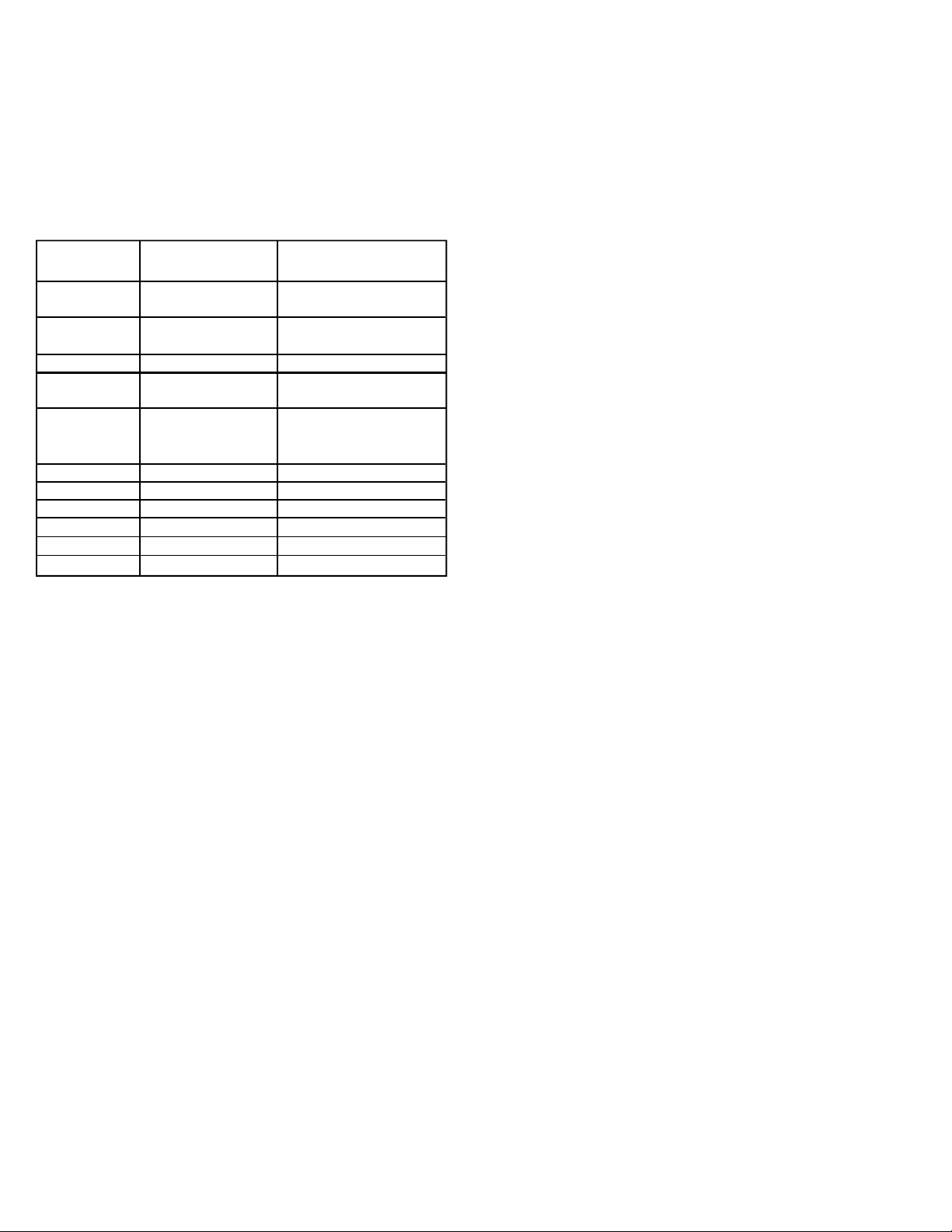
General Specifications
These specifications are based on an instrument operating in an ambient temperature of 5 to 90 degrees Fahrenheit, at a relative humidity of
less than 80%, which is within one year of calibration.
The accuracy column indicates the percent of possible error based on
the reading displayed, plus an additional allowance for drift based on
the value of the least significant digits of the selected range. This is stated as: ±(N% + N digits).
AC Volts and Current specified for frequency ranges between 50 and
500 Hertz.
Standard and Optional Accessories
Standard
Test Leads . . . . . . . . . . . . . . . . . . . . . . . . . . . . . . . . . . . . . . . . . . .ATL55
Optional
AC/DC Clamp Adapter 400 amp . . . . . . . . . . . . . . . . . . . . . . . . .CA30
AC/DC Clamp Adapter 1000 amp . . . . . . . . . . . . . . . . . . . . . . . .CA40
Soft carrying case . . . . . . . . . . . . . . . . . . . . . . . . . . . . . . . . . . . . .ACC315
Hard carrying case . . . . . . . . . . . . . . . . . . . . . . . . . . . . . . . . . . . .AC506
Flame safeguard test kit . . . . . . . . . . . . . . . . . . . . . . . . . . . . . . . .ATLFSG
Microwave diode booster test lead . . . . . . . . . . . . . . . . . . . . . . .ATL60
Temperature probe adapter . . . . . . . . . . . . . . . . . . . . . . . . . . . . .TA2K
DM384-MAN P. 9
Frequency (Hz)
AC Volts
Dc Volts
DC mV
Resistance
Capacitance
DC µA
DC mA
DC 10A
AC µA
AC mA
AC 10A
±(0.5% reading + 2 digits)
±(1.5% reading + 5 digits)
±(0.5% reading + 3 digits)
±(0.5% reading + 3 digits)
±(1.0% reading + 3 digits)
±(3.0% reading + 7 digits)
±(3.0% reading + 4 digits)
±(1.0% reading + 3 digits)
±(1.0% reading + 3 digits)
±(2.5% reading + 3 digits)
±(2.0% reading + 5 digits)
±(2.0% reading + 5 digits)
±(3.0% reading + 5 digits)
4kHz, 40kHz, 400kHz,
4MHz, 40MHz, 400mHz
400mV, 4V, 40V, 400V
750V
400mV, 4V, 40V,
400V, 1000V
400mV
400, 4k, 40k,
400k, 4M, 40M
4nF, 40nF, 400nF, 4µF,
40µF, 400µF,
4,000µF, 40,000µF
40µA, 400µA
40mA, 400mA
10A
40µA, 400µA
40mA, 400mA
10A
Page 11

Limited Warranty
The DM384 is warranted to be free from defects in materials and workmanship for a period of
five years from the date of purchase. If within the warra n ty period your instrument should
become inoperative from such defects, the unit will be repaired or replaced at UEi’s option.
This warra n ty covers normal use and does not cover damage which occurs in shipment or
failure which results from alteration, tampering, accident, misuse, abuse, neglect or improper
maintenance. Batteries and consequential damage resulting from failed batteries are not
covered by warra n ty.
Any implied warranties, including but not limited to implied warranties of merchantability
and fitness for a particular purpose, are limited to the express warranty. UEi shall not be
liable for loss of use of the instrument or other incidental or consequential damages,
expenses, or economic loss, or for any claim or claims for such damage, expenses or
economic loss. A purchase receipt or other proof of original purchase date will be required
before warra n ty repairs will be rendered. Instruments out of warra n ty will be repaired (when
r e p a i r able) for a service charge. Return the unit postage paid and insured to:
1-800-547-5740 • FAX: (503) 643-6322
www.ueitest.com • Email: [email protected]
This warranty gives you specific legal rights. You may also have other rights which vary from
state to state.
DM384
Digital Multimeter
Copyright © 2007 UEi DM384-MAN 1/07
PLEASE
RECYCLE
 Loading...