

Page 1
1-800-547-5740 • Fax: (503) 643-6322
www.ueitest.com • email: [email protected]
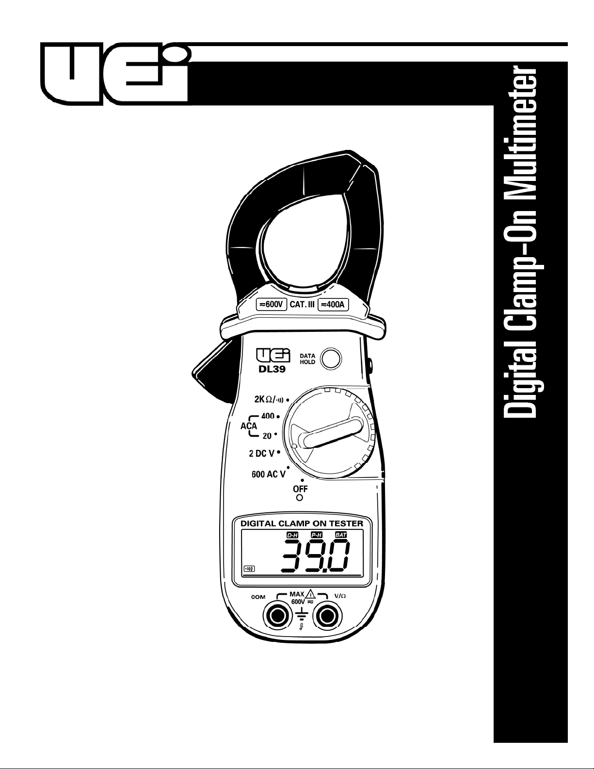
DL39
INSTRUCTION MANUAL
Page 2
• If any of the following indications occur during testing, turn
off the power source to the circuit under test:
• Arcing
• Flame
• Smoke
• Extreme Heat
• Smell of Burning Materials
• Discoloration or Melting of Components
• Read the safety precautions associated with the equipment being
tested and seek assistance or advice when performing
unfamiliar tasks.
• Keep your fingers away from the test lead metal probe contacts
and bus-bars when making measurements. Always grip the
instrument and test-leads behind the hand guards (molded into
the probes).
• In the event of electrical shock, ALWAYS bring the victim to
the emergency room for evaluation, regardless of the victim’s
apparent recovery. Electrical shock can cause an unstable heart
rhythm that may need medical attention.
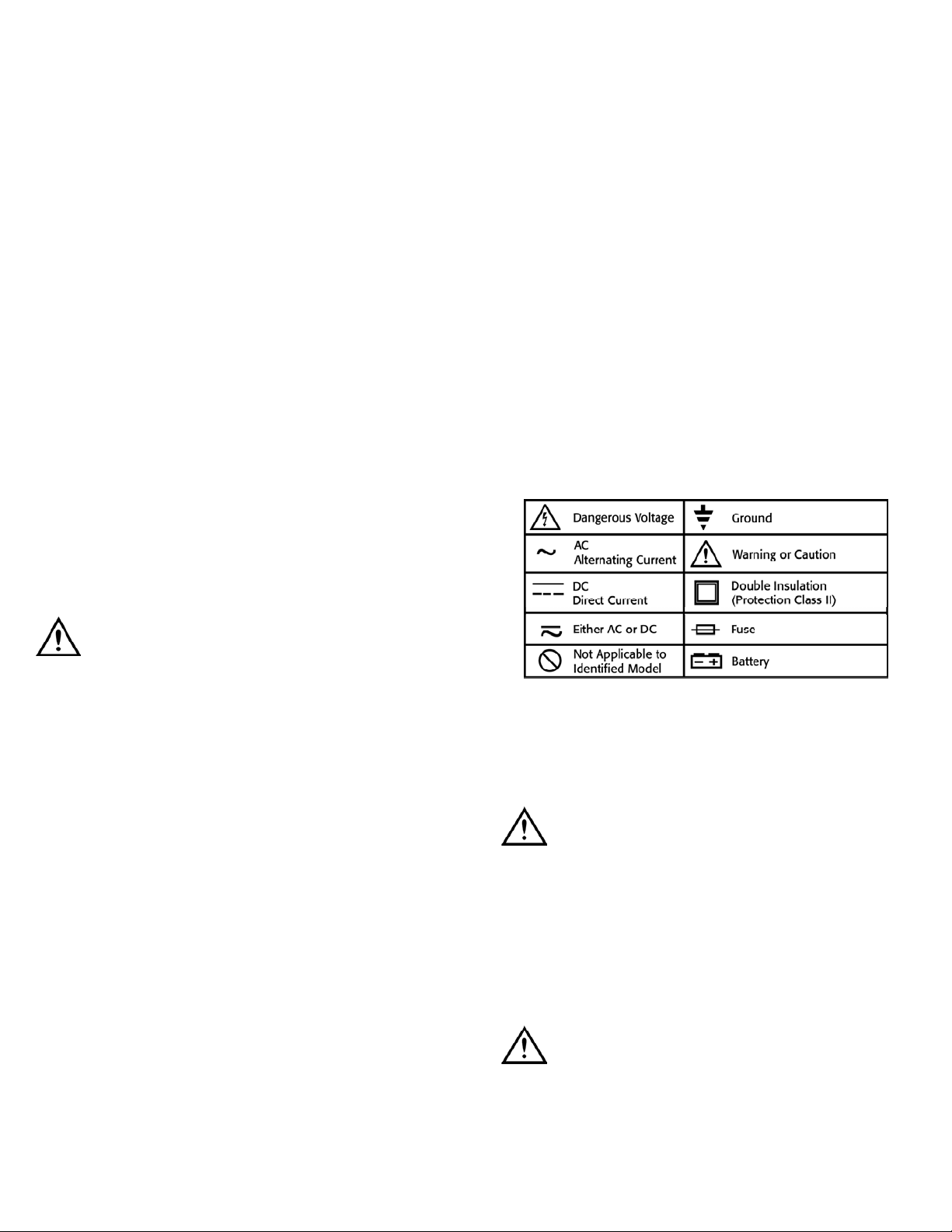
International Symbols
C o n t r ols and Indicators
1. C l a m p : Used to measure inductive AC current.
Opens to 1 1/4” (32 mm).
CAUTION!
The clamp uses a high-tension spring to close the jaw. DO NOT allow
fingers or objects to become pinched in the base as jaw closes.
2. Conductor Alignment Marks: Used to aid in the visual
alignment of a conductor when measuring inductive ampera g e .
Greatest accura c y is achieved when the conductor inside the clamp
is centered at the intersection of these marks.
3. Hand Guard: Used as a point of reference for the operator’s safety.
WARNING!
Always keep your hands and fingers behind the hand guards when
measuring current on exposed conductors. Contact may result
in serious safety.
Introduction
The DL39 is a hand-held, battery powered digital multimeter with
clamp-on current measuring ca p a b i l i ty. This instrument is ideal for
anyone that needs to make quick, accurate measurements of AC
inductive amperage, AC voltage and resistance. The low voltage DC
function accommodates accessory adapters.
Features include
• AC inductive amps
• AC volts
• DC volts for adapters
• Ohms (resistance)
• Continuity (with audible alert)
• Max capture
• Data hold
• Low battery indicator
• Rugged construction
• Compact size for easy access to tight areas
Safety Notes
Before using this meter, read all safety information carefully. In
this manual the word "WARNING" is used to indicate conditions
or actions that may pose physical hazards to the user. The word
"CAUTION" is used to indicate conditions or actions that may
damage this instrument.
WARNING!
Exceeding the specified limits of this meter is dangerous and can
expose the user to serious or possibly fatal injury.
• DO NOT attempt to measure any voltage that exceeds 600 volts
with this meter - UEi offers numerous alternatives for measuring
high voltage and current
• Voltages above 60 volts DC or 25 volts AC may constitute a
serious shock hazard
• DO NOT attempt to use this meter if either the meter or the test
leads have been damaged. Send unit in for repair by a qualified
repair facility
• Test leads must be fully inserted prior to taking measurements
• Always turn off power to a circuit (or assembly) under test before
cutting, unsoldering or breaking the current path. Even small
amounts of current can be dangerous
• Always disconnect the live test lead before disconnecting the
common test lead from a circuit
• When measuring high voltage, disconnect the power source before
making test lead connections. Connect the test leads to the meter
first then to the circuit under test. Reapply power
DL39-MAN P. 1
Page 3

LCD Display Functional Description
1. Numerical Value: Displays the total value of the units displayed.
2. Low Battery Indicator: This symbol appears when the battery
needs replacement.
NOTE: A low battery will adversely affect accuracy.
3. P-H: I n d i cate s the meter is displaying the maximum value measured
4. Data Hold: I n d i c ates the value displayed is held on screen
(the data hold button is pressed).
5. Minus: I n d i c ates the value measured has a negative polarity.
6. Continuity: I n d i cate s the meter is in the continuity measurement
mode and will sound a tone when measuring resistance below
approximately 50 ohms.
Operating Instructions
Auto-Power Off
This instrument is turned on and off using the rotary switch. When the
meter is moved out of the OFF position, into any of the measurement
positions, it will begin to display a measured value.
This instrument will remain on as long as it is in a measurement
position to allow long-term monitoring. Always store your meter in
the off position.
Max Capture
Use the “MAX CAPTURE” button on the right side of the instrument to
capture the highest measured value in any selected function or scale.
When Max Capture is selected, the symbol “P-H” appears at the top of
the screen and the highest measured value remains on the LCD display.
NOTE: This numerical data is not reset when the rotary switch is
moved from one function to another. For best, results, set the range
and function you intend to record prior to pressing the Max Capture
button, then leave the rotary switch in that position.
Press the Max Capture button again to return the instrument to the
real-time measurement mode.
4. Data Hold Push-button: Freezes the value displayed on the
digital read-out.
5. Max Capture Button: Used to capture and display the highest
measured value.
6. Clamp Lever: Opens and closes current clamp jaw.
7. Rotary Function Switch: Used to power the meter on and off, or
to select one of the available measurement functions.
NOTE: Measure inductive AC current using the clamp. Measure
volts AC and DC at the test lead inputs, resistance and continuity
at the test lead inputs.
8. Display: C o m m u n i c ates function, range, and value information to
the user.
9. Common Terminal: The black test lead is plugged into this
terminal to supply the ground or “low” reference for
all measurements.
10. Volt/Ohm (V/Ω) Terminal: The red lead is plugged into this
terminal. It is used for AC/DC volts, ohms, and continuity measurements.
11. Maximum Input Statements: M A X 600V indicates that a
m aximum of 600 Volts can be applied between the two terminals of
b e t ween earth ground and any terminal.
4
2
3
6
7
8
1
DL39-MAN P. 2
1
5
9
10
11
2 34
5
6
7
8
9
10
Page 4
Data Hold
The “DATA HOLD” button freezes the numerical data displayed on
the screen at the moment it is pressed. This function is engaged by
pressing the “DATA HOLD” button, located on the face of the
instrument, above the rotary switch. When Data Hold is active, the
letters “D-H” appear at the top of the digital display. To cancel Data
Hold, press the button again.
NOTE: The numerical value will remain displayed even if the rotary
dial is moved from its original position.
Selecting A Function and Scale
The rotary switch is used to turn the meter on, off, and to select the
measurement function and scale. The operator has control over the
function and resolution of the measurement. While this meter is
manufactured with a number of built in fail-safes, the potential to
damage the meter due to improper use does exist. Set the rotary
switch to the appropriate setting before touching the test leads to the
circuit under test.
Measuring Inductive Current
To measure current, clamp-on ammeters rely on the electromagnetic
field that occurs when electricity flows through a conductor. Prepare to
make your measurement by separating a single live conductor from any
other phase, neutral or ground conductor. Squeeze the clamp lever, and
place the open jaws around the isolated conductor. To attain the most
accurate reading, ensure the conductor is centered in the jaws of the
clamp, and the jaws are closed tight. The conductor must be able to fit
inside the 1 1/4” (32 mm) fully open jaws.
To measure inductive AC current:
1. Place the function select switch in the AC amp position
(ACA - 400 or 20).
2. Place the clamp jaw around a live conductor (as described above).
3. Allow meter to stabilize - Observe reading.
The maximum limit for this function is 400 amps AC. Too much
current will saturate the ferrous material in the clamp, and adversely
affect accuracy.
WARNING!
DO NOT attempt to take any unknown voltage or current
measurements that may be in excess of this meter’s maximum
limits. To avoid the risk of electrical shock and instrument discharge,
open circuit voltage for the circuit under test must not exceed
600 volts (RMS).
NOTE: For all measurements requiring the use of the meter leads,
insert the red lead into the V/Ω port and the black lead into the
COM port.
Measuring AC Voltage
WARNING!
Input voltages must not exceed 600 volts AC (RMS). When working
with high voltage or current a greater awareness of the physical safety
hazards is required. Connect the test leads to the meter, set the meter
to the desired function and range, and then connect to the circuit under
test. If an erroneous reading is observed, disconnect power immediately
and recheck all settings and connections.
When taking voltage measurements your meter must be connected in
p a rallel to the circuit, or circuit element, under test.
To measure DC or AC volts;
1. Insert the meter leads in jacks as instructed.
2. Set the rotary switch to the 600 AC V position.
3. Touch the test leads to the circuit under test.
4. Allow the meter to stabilize - Observe reading.
Using Adapters (2 DC V Position)
This meter includes a 2 Volt DC measurement function that offers 1 mV
(one millivolt) resolution. Many adapters (temperature, RPM, etc.) provide
a millivolt output to represent the measured value.
The spacing between terminals is an industry standard 3/4” inch (19 mm)
on center, which will accommodate most plug-in adapters manufactured
for multimeter use.
The output from a temperature adapter measuring 75 degrees Fa h r e n h e i t
would be displayed as “.075”. If 1, 2 00 degrees Fahrenheit were measured,
it would be displayed as “1. 200”. It is capable of displaying up to 19 9 9
units (degrees, RPM, etc.) positive or negative.
Measuring Resistance and Continuity
CAUTION!
Turn off power and discharge all capacitors in the circuit to be tested
before attempting “in circuit” resistance measurements. Failure to do
so may result in equipment or instrument damage. It is critical to both
the welfare of the meter, and the accuracy of the measurement, that
you remove all power to the circuit under test when making resistance
measurements. If any voltage is present in the test circuit, whether
from a conventional power supply, or energy stored in a capacitor, an
erroneous reading will result. This meter may be damaged if more than
600 volts are present.
NOTE: Test lead polarity is of no consequence when making continuity
or resistance measurements.
DL39-MAN P. 3
Page 5
Resistance or continuity can be measured while in the resistance
position. The continuity tone is used to make quick checks for
connections of electrical circuits, such as wiring splices, switch contacts,
relays and cables. The audible continuity tone sounds when the value
measured is approximately 30Ω or less. To measure resistance, or test
for continuity, follow these steps.
1. Set the rotary switch to the resistance function. (2KΩ/ )
2. Turn off power to the circuit under test and ensure there is no
residual voltage present from any source.
3. Touch the probes to the test points and read the display.
4. If the reading is below 30 ohms (30Ω), the continuity tone will sound.
NOTE: Be sure you have good contact between the test leads and
the circuit. Dirt, oil, solder-flux or other foreign matter alters the
reading value.
M a i n t e n a n c e
Service
WARNING!
Repair and service of this instrument is to be performed by qualified
personnel only. Improper repair or service could result in physical
degradation of the meter. This could alter the protection from electrical
shock and personal injury this meter provides to the operator. Perform
only those maintenance tasks that you are qualified to do.
These guidelines will help you attain long and reliable service from
your meter:
1. Calibrate your meter annually to ensure it meets original
performance specifications.
2. Keep your meter dry. If it gets wet, wipe it dry immediately.
3. Whenever pra c t i cal, keep the meter away from dust and dirt, which
can cause premature wear and collect on internal components.
4. Although your meter is built to withstand the rigors of daily use, it can
be damaged by severe impacts. Use reasonable caution when using
and storing the meter.
NOTE: When servicing the meter, use only the replacement
parts specified.
Battery: 9V, NEDA 1604 or IEC 6LR 61
Test lead set: ATL55
Cleaning and Decontamination
Periodically clean your meter’s case using a damp cloth. DO NOT use
abrasives, cleaning solvents or strong detergents, as they may damage
the finish or affect the reliability of the structural components.
Battery Replacement
Always use a fresh replacement battery of the specified size and ty p e .
Immediately remove the old or weak battery from the meter and dispose
of it in accordance with your local disposal regulations. Old or defective
batteries can leak chemicals that corrode electronic circuits.
WARNING!
To avoid electric shock, be sure to turn off the meter’s power and
disconnect both test leads from any equipment before you remove or
install batteries.
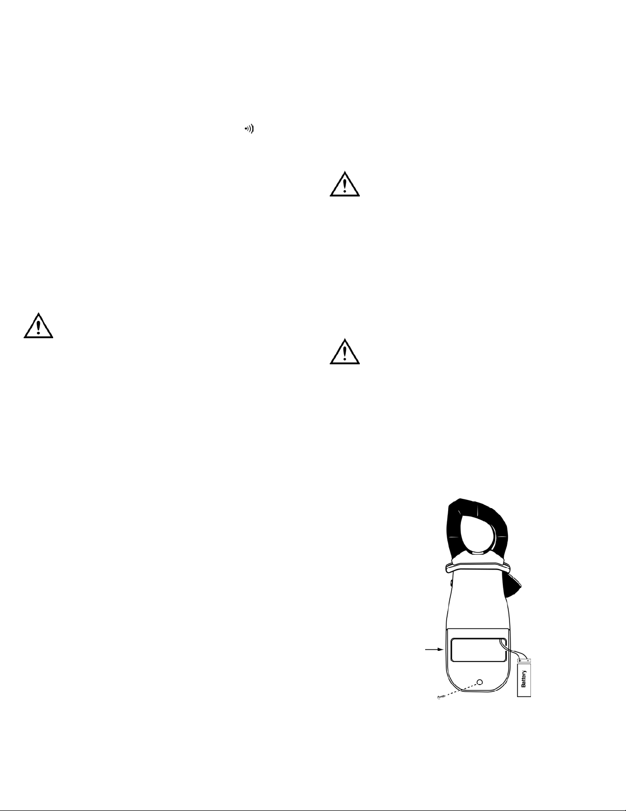
To install a new battery, follow these procedures:
1. Remove the screw from the battery compartment cover on the
back (lower half) of the meter and lift the cover (Fig 1).
2. Remove and discard the old battery. Always dispose of old batteries
promptly in a manner consistent with local disposal regulations.
WARNING!
Under NO circumstance should you expose batteries to extreme heat
or fire as they may explode and cause injury.
3. Place a fresh 9V battery in the compartment.
NOTE: If you do not plan to use the meter for a month or more,
remove the battery and store it in an area that won’t be damaged by
a leaking battery.
4. Reattach the battery compartment cover to the meter and
reinstall the screw.
Remove cover
DL39-MAN P. 4
(Fig 1)
Page 6
DL39-MAN P. 5
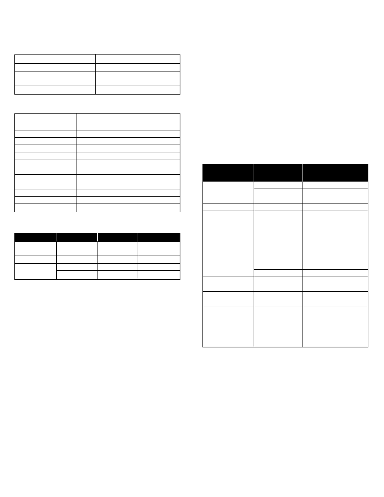
S p e c i f i c a t i o n s
Measurement limits
General specifications
Electrical specifications
Standard & Optional Accessories
Standard
Soft carrying case . . . . . . . . . . . . . . . . . . . . . . . . . . . . . . . . . . . . .AC259
Test leads . . . . . . . . . . . . . . . . . . . . . . . . . . . . . . . . . . . . . . . . . . . .ATL55
Optional
Soft carrying case . . . . . . . . . . . . . . . . . . . . . . . . . . . . . . . . . . . . .AC319
Large Soft carrying case . . . . . . . . . . . . . . . . . . . . . . . . . . . . . . . .AC519
Hard carrying case (service kits) . . . . . . . . . . . . . . . . . . . . . . . . .AC506
Plug-in line splitter . . . . . . . . . . . . . . . . . . . . . . . . . . . . . . . . . . . .ALS1
Temperature adapter . . . . . . . . . . . . . . . . . . . . . . . . . . . . . . . . . .TA2K
Dual input temperature adapter . . . . . . . . . . . . . . . . . . . . . . . . .TA2
Flame safeguard test adapter . . . . . . . . . . . . . . . . . . . . . . . . . . .DLMAT
Tro u b l e s h o o t i n g
AC Amperage
AC Voltage
DC Voltage
Ohms
Continuity
400 Amps
600 Volts
2 Volts
2000 Ohms
<30 ohms
Size (H x W x L)
Operating temperature
Storage temperature
Relative humidity
Weight
Clamp capacity
Calibration period
Open circuit voltage in
ohms/continuity function
IEC compliance
Battery
Battery life
7.68” x 3.06” x 1.79”
(195 x 77 x 46 mm)
32˚ to 113˚F (0˚ to 45˚C)
-4 to 140˚F (-20 to 60˚C)
0% to 80% RH
13 oz. (370g)
1 1/4” (32mm)
Annual
Approximately 3 Volts
1010-1 (CAT III 600 Volts)
9 Volt Alkaline (NEDA, 1604 or 6F22 or 006P)
62 hours continuous use w/ty p i cal alkaline battery
Function
Ohms (Ω)
Volts AC
Volts DC
Amps AC
(50-60 Hz)
Range
2 kΩ
600 V
2 V
20 A
400 A
Resolution
1 Ω
1V
1 mV
0.01 A
0.1 A
Accuracy
±(1.0% + 5 digits)
±(1.5% + 5 digits)
±(0.8% + 3 digits)
±(2% + 10 digits)
±(1.5% + 5 digits)
If I See This
Malfunction
Instrument does
not turn on
Data does not update
Known VOLTAGE/
RESISTANCE does not
appear on screen
Known CURRENT does
not appear on screen
Hunting/Seeking data
“OL” appears during
measurement
I Should
Check For
Battery Voltage
Battery clip
Date or MAX capture
Test leads
Dirt, corrosion or debris
on test point
Data or MAX capture
Measured conductor
Switch position
High input value
Then Take This
Corrective Action
Replace low battery
Ensure clip grips
battery posts tightly
Turn off Data/MAX Capture
Fully insert test leads for
voltage and resistance
measurements - Check for
continuity by shorting leads in
resistance mode
Clean test point or find
another point to measure the
same signal
Turn off Data/MAX Capture
Ensure ONLY ONE WIRE is in
the clamp jaw at a time
Ensure switch is not set
between functions
Change scale or reduce
input value
NOTE: “OL” is the normal
indication when no input is
applied in ohms
Page 7

Limited Warranty
The DL39 is warranted to be free from defects in materials and workmanship for a period of
three years from the date of purchase. If within the warra n ty period your instrument should
become inoperative from such defects, the unit will be repaired or replaced at UEi’s option.
This warra n ty covers normal use and does not cover damage which occurs in shipment or
failure which results from alteration, tampering, accident, misuse, abuse, neglect or improper
maintenance. Batteries and consequential damage resulting from failed batteries are not
covered by warra n ty.
Any implied warranties, including but not limited to implied warranties of merchantability
and fitness for a particular purpose, are limited to the express warranty. UEi shall not be
liable for loss of use of the instrument or other incidental or consequential damages,
expenses, or economic loss, or for any claim or claims for such damage, expenses or
economic loss. A purchase receipt or other proof of original purchase date will be required
before warra n ty repairs will be rendered. Instruments out of warra n ty will be repaired (when
r e p a i r able) for a service charge. Return the unit postage paid and insured to:
1-800-547-5740 • FAX: (503) 643-6322
www.ueitest.com • Email: [email protected]
This warranty gives you specific legal rights. You may also have other rights which vary from
state to state.
DL39
Digital Clamp-On Multimeter
Copyright © 2007 UEi DL39-MAN 1/07
PLEASE
RECYCLE
 Loading...