

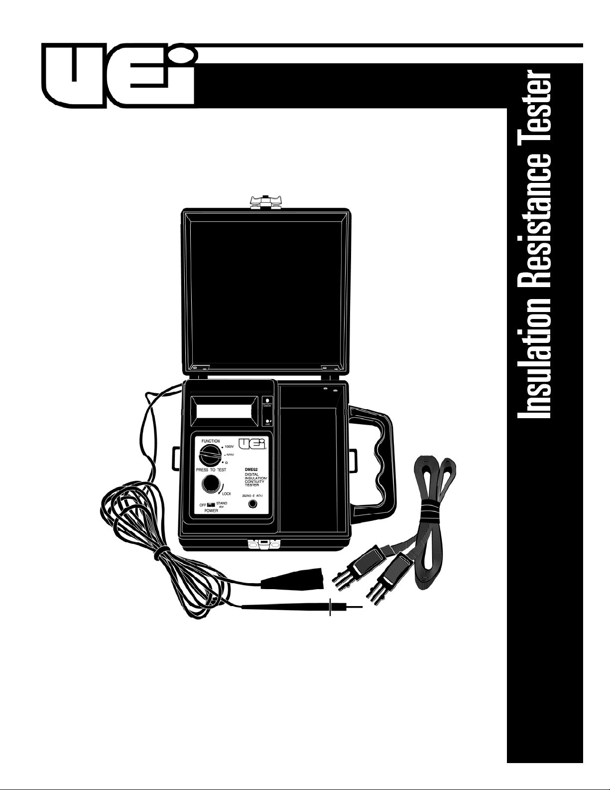
Page 1
1-800-547-5740 • Fax: (503) 643-6322
www.ueitest.com • email: info@ueitest.com
DMEG2
INSTRUCTION MANUAL
Page 2

C o n t r ols and Indicators
1. Rotary Selector Knob: Switches measurement function.
2. Ohms: This is the low resistance or “c o n t i n u i ty” position. Used to
i d e n t i fy low resistance circuits such as motor run and start winding
which may differ by only a few ohms.
3. 200MΩ (250, 500V): In this position approximately 500 V DC is
applied to the circuit under test when the TEST switch is pressed. The
0 - 2 0 0 M Ω range is used primarily to test insulation resistances which
have begun to degra d e .
4. 200MΩ (1000V): In this postilion approximately 1000 V DC
is applied to the circuit under test when the TEST switch is
pressed. This is the range which is normally used for preventive
maintenance measurements on electrical equipment. Insulation
resistance values in this application typically exceed 100MΩ.
5. ON/OFF switch: Slide the switch forward to turn the instrument
on, slide it back to turn the instrument off.
6. Test Switch: The TEST switch is normally OFF, spring loaded,
momentary action switch which “turns on” the DMEG2. The
momentary action is a safety feature. The test voltage generated
by the DMEG2 is automatically discharged when the TEST
switch is released.
Introduction
The DMEG2 Insulation Resistance Tester is a completely portable,
self-contained, four range, solid state test instrument.
Power is provided by eight internal, standard 1.5V, size AA (ABI)
batteries. An electronically regulated constant voltage generator
supplies the test voltage for the 2000MΩ range (1000V) and the
2000MΩ range (500V), and the 2000MΩ range (250V). The internal
batteries supply the power directly for the 0-200Ω low resistance range.
This rugged precision instrument can locate intermittent shorts,
defective electrical connections, insulation breakdowns or conductor
failures due to the effects of temperature, moisture, abrasion, corrosion,
or other environmental conditions.
One of the most effective applications, and one of the most overlooked
applications for the DMEG2 is in the field of preventive maintenance.
For example, when the insulation properties of a hermetic compressor
motor begins to fail it usually does so gradually at first. A routine,
periodic monitoring of the insulation resistance of the start and run
winding will usually show evidence of a potential burn out well in
advance of the actual occurrence.
Features include
• Battery operated
• Automatic circuit discharge
• Solid state circuitry
• LCD display
• Automatic zero adjust
• Four ranges
• Automatic low battery indication
• Audible warning signal
• Live circuit indicator
Safety Notes
Before using this instrument, read all safety information carefully. In
this manual the word "WARNING" is used to indicate conditions
or actions that may pose physical hazards to the user. The word
"CAUTION" is used to indicate conditions or actions that may
damage this instrument.
International Symbols
DMEG2-MAN P. 1
1
2
Electrical shock can cause an unstable heart rhythm
that may need medical attention.
3
4
5
6
Page 3
DC Devices
Independent insulation tests may be carried out between the electrical
sections of a DC generator, or motor, and ground. Separate the brushes
from the commutator (Fig. 2) to isolate the brushes and field coil
functions from the rotor. These separated sections may be easily tested
independently of each other. This does not apply, however, when an
overall insulation test is intended. In this case the brushes remain in
contact with the commutator so that the three sections (brushes, coils
and rotor) may be tested integrally.
Hermetic Compressor
Most hermetic compressor utilize a three terminal block for making
electrical connections to the sealed unit (Fig. 3). The connection may be
made by an “umbilical” cord or a screw terminal, but the most common
connection method is usually with a relay that pushes onto the S and M
terminals and an overload protector that pushes onto the C terminal.
(Refer to the manufacturer’s manual)
Shut off power to the unit under test and remove the connections to
the compressor terminal block. Connect the red test lead of the DMEG2
tot he C terminal and the black test lead to the frame, or ground.
Measure the insulation resistance. Low values of insulation resistance
may indicate the presence of contaminated refrigerant. Refer to the
chapter on interpreting test results.
Winding continuity may be checked by setting the SELECTOR switch on
OHMS. Check the start and run winding by measuring the resistance
between the C terminal and the S or M terminal.
Operating Instructions
CAUTION!
Observe all safety precautions when the CONTROL switch is set to
either the 2000MΩ (500V) or the 2000MΩ (1000V) position. Connect
the DMEG2 test leads to the circuit under test before operating the
TEST switch. DO NOT touch the battery clip ends of the test leads when
the TEST switch is in the TEST position. Some electrical equipment,
especially cables, may retain an electrical charge when disconnected
from the line. It is a good practice to discharge such equipment with
grounding straps, or other suitable devices, before touching or making
connections. The DMEG2 automatically discharges the test circuits when
the spring loaded TEST switch is released.
WARNING!
Remove all power to the circuit under test when making resistance
measurements. If any voltage is present in the test circuit an erroneous
reading will result.
Motors and Generators
Disconnect the motor from the line either by opening the main switch
or by disconnecting the wires at the motor terminals. if the main switch
is opened and measurements are made at the switch contacts, then the
insulation resistance of all components between switch and motor will
be measured simultaneously. If a fault is indicated it will be necessary to
test each section separately.
AC Devices
The basic test is to connect the red test lead of the DMEG2 to one of
the motor terminals, or wire, and the black test lead to the frame or
housing (Fig. 1). Start and run winding may be checked for correct
resistance by setting the SELECTOR switch to OHMS and connecting
one test lead to the common winding terminal and the other test lead
to the start or run terminal.
DMEG2-MAN P. 2
(Fig 2)
(Fig 1)
(Fig 3)
Page 4

Circuit Beakers and Switches
Disconnect the circuit breaker or switch from the line. Trip or open the
device and check the insulation resistance between the pole terminals
by connecting one test lead to one pole and the other test lead to the
remaining pole pair. Low values of insulation resistance may be caused
by the presence of contaminates or by carbon arc lines in the insulator
block. If the cause of the low readings is determined to be caused by
carbon arcing, the device should be replaced (Fig. 4).
Cables
Disconnect the cable from the line. As a safety precaution, discharge
the cable by shorting the individual leads to the sheath. This is
especially necessary when testing coaxial cables. Disconnect the cable
from the equipment to which the cable is attached. This will eliminate
any influence of the equipment on the test readings.
Several types of insulation resistance measurements are normally
made: lead to lead(s), lead to sheath, lead to ground, etc. As an
example, when only one of the conductors in a multiconductor cable
is to be insulation tested, the conductor to be tested should be
connected to the test lead of the DMEG2. All of the other conductors
should be connected to the cable shield, which is then connected
to the test lead.
Factors Affecting Actual Insulation Resistance Values
Unlike most basic electrical measurements, such as voltage current,
and resistance, the actual insulation resistance of a device may differ
from the measured value of insulation resistance. This is because the
temperature at which the measurement and the duration of the
measurement may all affect the reading. It may be necessary to correct
the measured insulation resistance value to arrive at a more true value
of insulation resistance. The effects of these factors are discussed below.
Temperature
Most electrical insulation materials have a negative temperature
coefficient. This means that the magnitude of insulation resistance
decreases as the temperature at which the measurement is taken
increases. For example, the insulation resistance of a transformer
measured at 68˚F may be three times the value of the same transformer
measured at a temperature of 100˚F.
If periodic measurements of a device are made at different
temperatures then the temperature must be adjusted to a base value,
usually 68˚F. Otherwise, the insulation resistance of a device may
appear to fluctuate widely (the sign of unstable or deteriorating
insulation) when in reality the actual insulation resistance may be
quite stable. Of course, if the insulation resistance measurements are
always made at, or near, the same temperature then the use of
temperature correction charts may be omitted.
DMEG2-MAN P. 3
Chart 1
Rotating Equipment Temp. (˚F) Class A
Temperature Correction Chart
Corrected to 68˚F Ambient
Rc = K Rm
Rc = Corrected Resistance Value
K = Correction Factor
Rm = Measured Resistance Value
(Fig 4)
Page 5

Chart 1 is a temperature correction chart for Class A rotating
equipment. For example, if a reading of 100 Megohm were obtained
at a temperature of 110˚F then the corrected insulation resistance is
Rc=KRm=6 x 1--=600 Megohms, when Rc is the corrected resistance, K
is the temperature correction factor obtained from the graph, and Rm
is the measured resistance. Chart 2 is a temperature correction chart
for oil filled transformer winding.
Humidity
Measurements made in a humid environment will result in lower
insulation resistance values than measurements taken in a dry
environment. The geometry of the equipment will also have an
influence on the measurements. For example, rotating machinery
has many more leakage paths, especially on the commutators and
armatures, where moisture can be trapped, than would a sealed
transformer or shielded cable. The best practice is to take insulation
resistance measurements when the equipment is safely above the dew
point. In this case, the effects of humidity can largely be ignored.
However, it is always advisable to assure that the equipment be free
of oil, dust, etc., which might affect the test results.
Time Duration of Measurement
The amount of time during which the test voltage is applied will also
affect the reading. Typically, with good insulation, the measured value
of insulation resistance will slowly increase as long as the test voltage
is applied. This is due to the dielectric absorption effect of the applied
DC voltage on the bulk insulation resistance. Refer to Figure 6 for a
representative graph of insulation resistance as a function of the time
during which the test voltage is applied.
A standard test of insulation integrity is to measure the insulation
resistance at 30 seconds and 60 seconds after the test voltage is
applied. The ratio of the reading at 60 seconds to the reading at
30 seconds is called the Dielectric Absorption Ratio.
DMEG2-MAN P. 4
Chart 2
Transformer Winding Temperature (˚F)
Temperature Correction Chart
Corrected to 68˚F Ambient
Rc = K Rm
Rc = Corrected Resistance Value
K = Correction Factor
Rm = Measured Resistance Value
Chart 3
Time (Seconds)
Page 6

DMEG2-MAN P. 5
Typically, a ratio of 1.25 represents the borderline between an insulation
resistance of questionable integrity and of fair integrity. A ratio of 1.6
and above is indicative of insulation of very good integrity. The
Dielectric Absorption Ratio method of testing insulation resistance is
generally not affected by the temperature at which the measurements
are taken. This is one of the advantages of this method. The Dielectric
Absorption Ratio of the example shown in (Fig 6) is 1.5.
Interpretation and Recording of Data
Periodic measurements of insulation resistance of a device, taken
under the same conditions, generally result in much more meaningful
results than measurements taken just once, or at random intervals.
The measurement interval may be weekly, monthly, quarterly or
yearly. This interval chosen will depend in general upon the conditions
under which the device is operated and the cost of suffering an
unexpected breakdown.
The device which operates under conditions of high temperatures,
humidity, load and vibration should be tested more frequently than the
same device which operates under less stressful conditions.
The following “rules” are guidelines which may be used to help
determine whether a piece of equipment is operating normally or
whether it should be pulled out of service and repaired or replaced.
However, the equipment manufacturer’s data on insulation resistance
values and test procedures should be consulted when available.
One Kilovolt/One Megohm Rule
This is an old, generalized rule that states that electrical equipment
rated up to 1000 volts should have minimum insulation resistance
of one-Megohm. Above 1000 volts rating the minimum insulation
resistance should be one Megohm for each 1000 volts of rating.
NOTE: This rule of thumb does not apply to the testing of
hermetic compressors.
Trend Rule
Hermetic Compressor
Dielectric Absorption Ratio Rule
Recording Data
A package of Data Log Cards is supplied with the DMEG2. The use
of these log cards will facilitate the recording and plotting of data
necessary to monitor and evaluate the insulation resistance history and
integrity of an individual piece of equipment. Space is provided on the
front of the card to record the equipment identity and to plot a graph
of insulation resistance values from 0.1 to 1000 Megohms. Space is
provided on the back of the card to record the supporting tabular data.
It is not necessary to make an entry in every column on the back of the
Data Log Card each time a measurement is taken. However, the more
data that is recorded the easier it will be to determine the reason for
changes in the measured insulation resistance.
Determining Moisture Content
The amount of insulation resistance, when drying out or baking
transformers, motors, and generators is an excellent indicator of the
amount of moisture remaining in the device. The insulation resistance
reading will increase as the moisture is driven off. In this way optimum
curing times can be determined.
Insulation Resistance Values Interpretation
High and holding steady Condition good
High but tapering off Breakdown may be starting
Decrease test interval or
repair equipment
Moderately low and holding May be all right. Depends on
steady history of device. Should try to
identify cause of low reading.
Low and declining Failure probable in rear future.
Repair or replace.
Insulation Resistance Values Interpretation
100 Megohms & above Condition good
50 to 100 Megohms Evidence of moisture in
refrigerant. Check drier.
20 to 50 Megohms Excessive moisture in refrigera n t .
Examine system.
Below 20 Megohms Failure of system likely.
Purge system
Ratio Interpretation
Above 1.6 Condition good
1.25 to 1.6 Condition moderately good
1.1 to 1.25 Condition questionable to
unstable
Page 7

DMEG2-MAN P. 6
M a i n t e n a n c e
The DMEG2 is a precision test instrument. DO NOT operate the DMEG2
where it will be subjected to high levels of temperature, humidity, or
mechanical shock.
Cleaning
Use a damp cloth and mild soap to clean the case. DO NOT use harsh
detergents or abrasive as these may harm the finish or weaken the
structure with an adverse chemical reaction.
Battery replacement
The internal batteries supply the operating power for the DMEG2.
Dispose of batteries in accordance with your local solid-waste disposal
regulations. Never expose batteries to high temperature or incineration.
To test for defective or weak batteries:
1. Press TEST switch.
2. If LED does not flash, replace battery.
A. Remove the flat head screws which secure the DMEG2
back panel
B. Carefully remove the back panel to gain access to the battery
compartment located in the case back.
C. Remove the batteries and install eight new 1.5V, size AA
alkaline batteries (stock no ABB). Observe battery polarity as
shown on the label below the battery holders.
D. Before replacing the back panel, repeat steps 1-2 above, to
verify that the LED is flashing.
E. Replace the back panel.
If the DMEG2 is to be stored, or left unused for long periods of time,
remove the batteries. This is a standard precaution
Trouble Shooting
Current leakage paths are difficult, if not impossible, to detect with a
conventional multitester. The resistance of such leakage paths may
be too high to measure with a multitester but still be low enough to
cause inefficient operation, overheating, and other indications of
operating problems.
S p e c i f i c a t i o n s
Ranges
Open Circuit Terminal Voltage
(refer to chart 1)
Short Circuit Terminal Current
Accuracy
Batteries
Standard Accessories
Standard
Batteries, 1.5V, size AA . . . . . . . . . . . . . . . . . . . . . . . . . . . . . . . .AB8
Test leads . . . . . . . . . . . . . . . . . . . . . . . . . . . . . . . . . . . . . . . . . . .ATL15
Insulation Resistance Data Log Cards (pkg) . . . . . . . . . . . . . . .ADC1
0-2000MΩ (1000 DC V test voltage)
0-2000MΩ (500 DC V test voltage)
0-2000MΩ (250 DC V test voltage)
0-200Ω
0-2000MΩ: +950 DC V (approximately)
0-2000MΩ: +480 DC V (approximately)
0-2000MΩ: +250 DC V (approximately)
0-200Ω: +170 DC mA (approximately)
0-2000MΩ: 1.2 DC mA (approximately)
0-2000MΩ: 1.0 DC mA (approximately)
0-2000MΩ: 1.1 DC mA (approximately)
0-200Ω: 24 DC mA (approximately)
O H M 250 V 50 0 V 10 0 0 V
0 - 2 0 0 Ω ± 1.5% ±2 dgt
0 - 10 0 M Ω ± 1.5% ±3 dgt ± 1.5% ±2 dgt
10 0 - 20 0 M Ω ±2% ±5 dgt
20 0 - 170 0 M Ω ±3% ±7 dgt ±3% ±4 dgt ±3% ±3 dgt
170 0 - 2 0 0 0 M Ω ±4% ±8 dgt ±4% ±6 dgt ±4% ±5 dgt
2000 M
Range
200 M
Range
Load Resistance Megohms
Terminal Voltage VS Load Resistance
Page 8

Limited Warranty
The DMEG2 is warranted to be free from defects in materials and workmanship for a period
of three years from the date of purchase. If within the warra n ty period your instrument should
become inoperative from such defects, the unit will be repaired or replaced at UEi’s option.
This warra n ty covers normal use and does not cover damage which occurs in shipment or
failure which results from alteration, tampering, accident, misuse, abuse, neglect or improper
maintenance. Batteries and consequential damage resulting from failed batteries are not
covered by warra n ty.
Any implied warranties, including but not limited to implied warranties of merchantability
and fitness for a particular purpose, are limited to the express warranty. UEi shall not be
liable for loss of use of the instrument or other incidental or consequential damages,
expenses, or economic loss, or for any claim or claims for such damage, expenses or
economic loss. A purchase receipt or other proof of original purchase date will be required
before warra n ty repairs will be rendered. Instruments out of warra n ty will be repaired (when
r e p a i r able) for a service charge. Return the unit postage paid and insured to:
1-800-547-5740 • FAX: (503) 643-6322
www.ueitest.com • Email: info@ueitest.com
This warranty gives you specific legal rights. You may also have other rights which vary from
state to state.
DMEG2
Insulation Resistance Tester
Copyright © 2007 UEi DMEG2-MAN 1/07
PLEASE
RECYCLE
 Loading...