

Universal Enterprise DM420 Installation Manual

1-800-547-5740 • Fax: (503) 643-6322
www.ueitest.com • email: info@ueitest.com
DM420
INSTRUCTION MANUAL
• Read the safety precautions associated with the equipment being
tested and seek assistance or advice when performing
unfamiliar tasks.
• Keep your fingers away from the test lead metal probe contacts
and bus-bars when making measurements. Always grip the
instrument and test-leads behind the hand guards (molded into
the probes).
• In the event of electrical shock, ALWAYS bring the victim to
the emergency room for evaluation, regardless of the victim’s
apparent recovery. Electrical shock can cause an unstable heart
rhythm that may need medical attention.
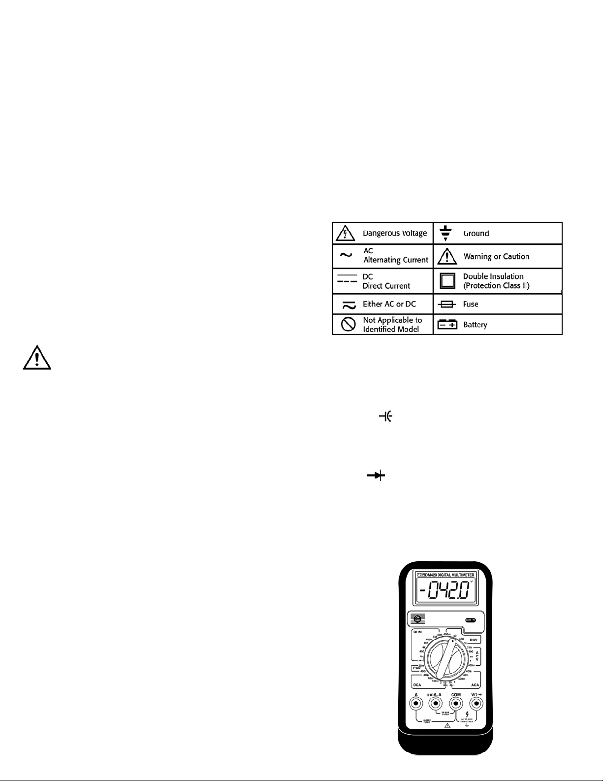
International Symbols
C o n t r ols and Indicators
1. “A” Input Jack: The red test lead is plugged into this jack for
measuring current on the 2 and 10 AC or DC amp functions.
2. “mAµA” ( ) Input Jack: The red test lead is plugged into
this jack for measuring mA or µA on either AC or DC current functions.
3. “COM” Input Jack: The black test lead is plugged into this jack
for all measurements.
4. “VΩ” ( ) Input Jack: The red test lead is plugged into this
jack for all AC volts, DC volts, OHM, Continuity Buzzer and Diode
test functions.
5. “ON/OFF” Push-button: Turns the meter on and off.
6. “Hold” Push-button: Freezes the reading on the LCD for all
functions and ranges.
Introduction
The DM420 combines the best features of the DM383 and DM410 with a
wide capacitance range. This new feature allows measurement of run and
start ca p a c i t o r s .
Features include
• 3-3/4 digit LCD display with 0.91” tall numerals
• Data Hold
• Diode Test
• Rubber boot
• 600 Volt fuse protection on all current ranges
• Continuity buzzer
• Auto polarity
• Capacitance up to 20,000 µF
Safety Notes
Before using this meter, read all safety information carefully. In
this manual the word "WARNING" is used to indicate conditions
or actions that may pose physical hazards to the user. The word
"CAUTION" is used to indicate conditions or actions that may
damage this instrument.
WARNING!
Exceeding the specified limits of this meter is dangerous and can
expose the user to serious or possibly fatal injury.
• DO NOT attempt to measure any voltage that exceeds 1000 V DC
or 750 V AC peak
• Voltages above 25 volts DC or 25 volts AC may constitute a
serious shock hazard
• DO NOT attempt to use this meter if either the meter or the test
leads have been damaged. Send unit in for repair by a qualified
repair facility
• Test leads must be fully inserted prior to taking measurements
• Always turn off power to a circuit (or assembly) under test before
cutting, unsoldering or breaking the current path. Even small
amounts of current can be dangerous
• Always disconnect the live test lead before disconnecting the
common test lead from a circuit
• When measuring high voltage, disconnect the power source before
making test lead connections. Connect the test leads to the meter
first then to the circuit under test. Reapply power
• If any of the following indications occur during testing, turn
off the power source to the circuit under test:
• Arcing
• Flame
• Smoke
• Extreme Heat
• Smell of Burning Materials
• Discoloration or Melting of Components
DM420-MAN P. 1
1
 Loading...