

Universal Enterprise DM397 Installation Manual
1-800-547-5740 • Fax: (503) 643-6322
www.ueitest.com • email: info@ueitest.com
DM397
INSTRUCTION MANUAL
Introduction
The DM397 is an advanced full-featured digital multimeter designed for
engineers, HVAC and electrical technicians, whose work demands
greater accuracy and resolution. The RS232 data logging kit and software (included) allows any measured parameter to be monitored or
recorded to a PC for further analysis. The 50,000 count dual display
shows two parameters simultaneously eliminating the need to toggle
between selections. The DM397 stands alone as the best value in highend multimeters.
Features include
• True RMS
• 1000 AC/DC & AC+DC Volts
• 1000 AC/DC & AC+DC Amps
• dBm & dBV
• High Resolution Resistance & Conductance
• Frequency / Duty Cycle
• Pulse Width
• Temperature / Capacitance / Continuity
• Relative Mode and (REL∆) mode
• Data logging kit with software
• Data Storage & Recall
• MIN/MAX/AVG
• 1mS Peak Capture
• Audible & Visual input warning
• Backlit dual displays with analog bar-graph
• All input, ranges, & functions protected to 1000 V CAT III
• Closed case calibration
• Access to battery and fuses without breaking calibration seals
• Open fuse detection
Safety Notes
Before using this meter, read all safety information carefully. In
this manual the word "WARNING" is used to indicate conditions
or actions that may pose physical hazards to the user. The word
"CAUTION" is used to indicate conditions or actions that may
damage this instrument.
• Allways follow industry standard safety practices including protetive
clothing, gloves and safety glasses when appropriate
• Do not attempt to measure any voltage that exceeds the
ca t e g o ry b ased rating of this meter
• Do not attempt to use this meter if either the meter or the test
leads have been damaged. Turn it in for repair at a qualified
repair facility
• Ensure meter leads are fully seated by making a quick continuity
check of the leads prior to making voltage measurements
• Keep your fingers away from the test lead’s metal probe
contacts when making measurements. Always grip the leads behind
the finger guards molded into the probes
• Use a current clamp adapter when measuring current that may
exceed 10 amps. See the accessories in UEi’s full-line ca t a l o g
• Do not open the meter to replace batteries or fuses while the
probes are connected
WARNING!
Exceeding the specified limits of this meter is dangerous and can
expose the user to serious or possibly fatal injury.
• Voltages above 60 volts DC or 25 volts AC may constitute a
serious shock hazard
• Always turn off power to a circuit (or assembly) under test
before cutting, unsoldering, or breaking the current path Even small amounts of current can be dangerous
• Always disconnect the live test lead before disconnecting the
common test lead from a circuit
• In the event of electrical shock, ALWAYS bring the victim to
the emergency room for evaluation, regardless of the victim’s
apparent recovery - Electrical shock can cause an unstable heart
rhythm that may need medical attention
• Higher voltages and currents require greater awareness of
physical safety hazards - Before connecting the test leads; turn
off power to the circuit under test; set the meter to the desired
function and range; connect the test leads to the meter first, then
to the circuit under test. Reapply power
• If any of the following indications occur during testing, turn
off the power source to the circuit under test:
• Arcing
• Flame
• Smoke
• Extreme Heat
• Smell of Burning Materials
• Discoloration or Melting of Components
CAUTION!
Do not attempt to remove the meter leads from the circuit under test.
The leads, the meter, or the circuit under test may have degraded to
the point that they no longer provide protection from the voltage and
current applied. If any of these erroneous readings are observed,
disconnect power immediately and recheck all settings and connections
Compliance
The DM397 complies with IEC 1010-1 (1995), UL 3111-1 (6.1995), EN
61010-1 (1995), CSA C 22.2 No, 1010-1 - 92; Overvoltage 1000V CAT III.
Electromatic Compatibility
The meter meets EN61326 : 1997 A1 : 1998.
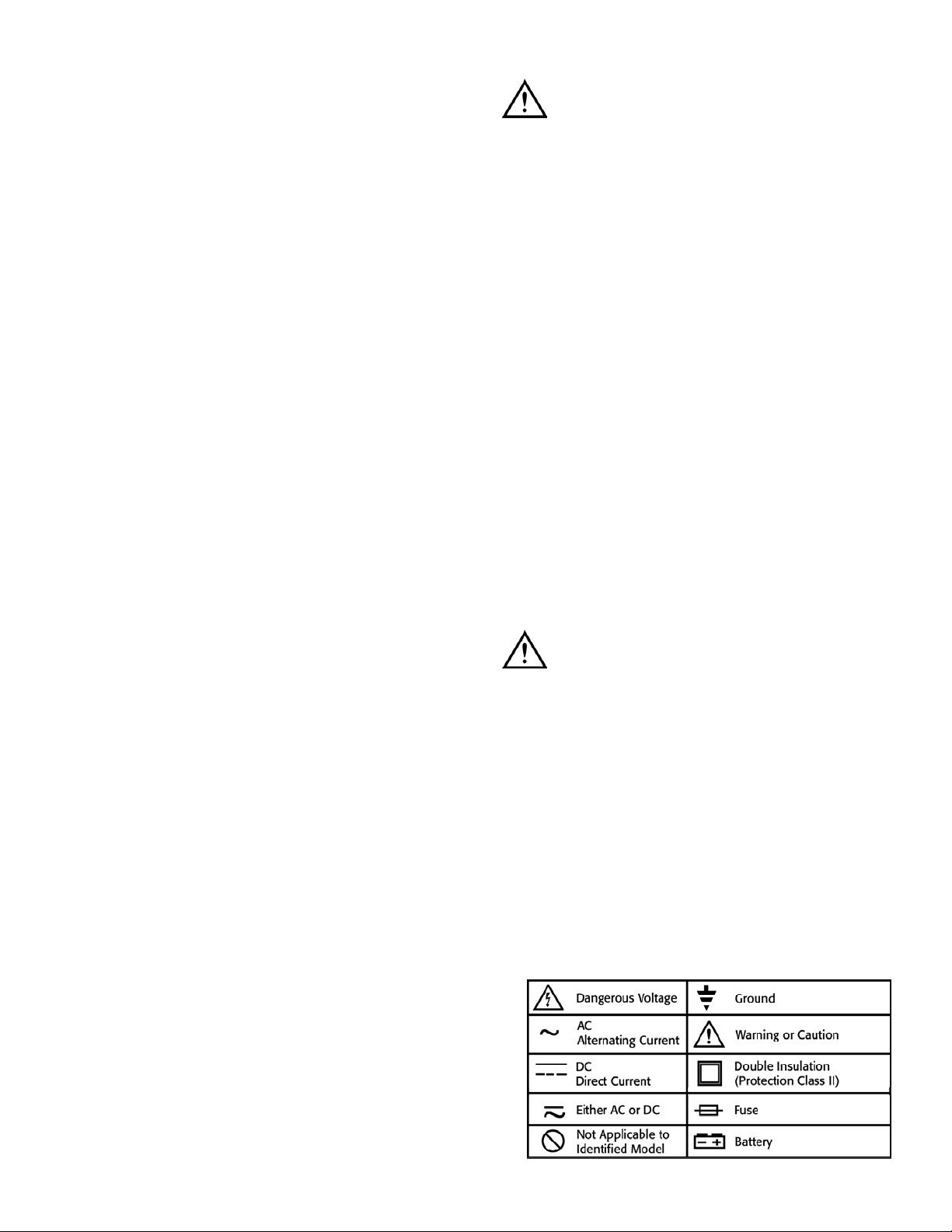
International Symbols
DM397-MAN P. 1
Rotary Switch
To turn the meter on, turn the rotary switch from the OFF position to
any switch setting.
If you want to view the full display (all segments illuminated), press and
hold the “HOLD” push-button while turning the meter on. Release the
button to return to normal viewing.
Turn the meter on by selecting any measurement function. The meter
presents a standard display for that function (range, measurement units,
on screen menu, etc.). The display may also show other information
based on the choices made through the on-screen
menu selection.
Use the on screen menu selection or the other push-buttons to select
any rotary switch alternative function.
When you turn the rotary switch from one function to another, a display
for the new function appears. Button choices made in one function do
not carry over into another function.
OFF: Turns the meter off. Setup parameters and stored
measurements are saved.
mV: Select either Millivolt AC RMS or DC Voltage measurements.
Compatible with various adapters.
V: Volts AC RMS, Volts DC, Volts AC+DC total RMS,
Volts AC/DC dual display, dBm and dB.
Hz: Frequency measurement. Duty cycle and pulse width are
also displayed if they are selected with the on-screen menu.
Ω : Access to resistance measurement, continuity test and
capacitance measurement. Conductance (1/Ω) is also dis
played in the secondary display when measuring resistance.
: Diode measurement (Forward bias voltage drop).
Temp: Temperature measurement in degrees Fahrenheit
or Centigrade.
µA: Select from Microamp AC RMS, Microamp DC, Microamp
AC+DC total RMS, and Microamp AC/DC dual display.
A: Select from Amperes AC RMS, Amperes DC, Amperes
AC+DC total RMS, and Amperes AC/DC dual display.
mA: Select from Milliamps AC RMS, Milliamps DC, Milliamps
AC+DC total RMS, and Milliamps AC/DC dual display.
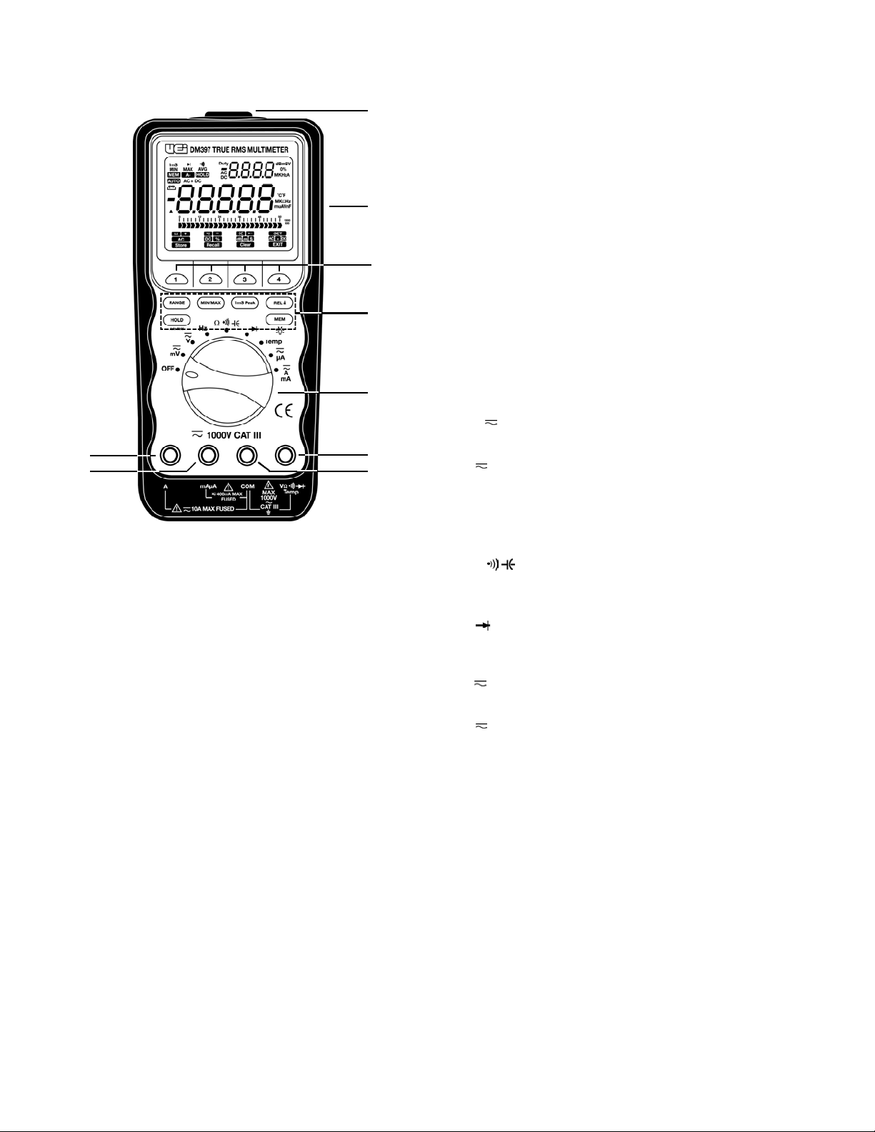
C o n t rols and Indicators
1. Digital Display: Readings are displayed on a 4-4/5 digit,
50,000 count (primary display) and 5,000 count
(secondary display).
2. Rotary Switch: Used to turn the power on or off and to select
a function.
3. On Screen Menu Selection Push-buttons: Used to select
functions from the on screen menus.
4. Special Function Push-buttons: Used to select special
functions and features.
5. Input Terminal 10A: (20A for 30 sec.) current
measurement function.
6. Input Terminal for Milliamp: (mA) and micro amp (µA)
current measurement function.
7. Common Input Terminal: (Ground reference) for all
measurement functions.
8. Input Terminal for Multiple Functions: Input jack for all
measurements except current (A, mA, µA) measurement functions.
9. RS-232 Optical Interface: Allows connection to a computer.
6
DM397-MAN P. 2
5
2
8
7
4
3
1
9
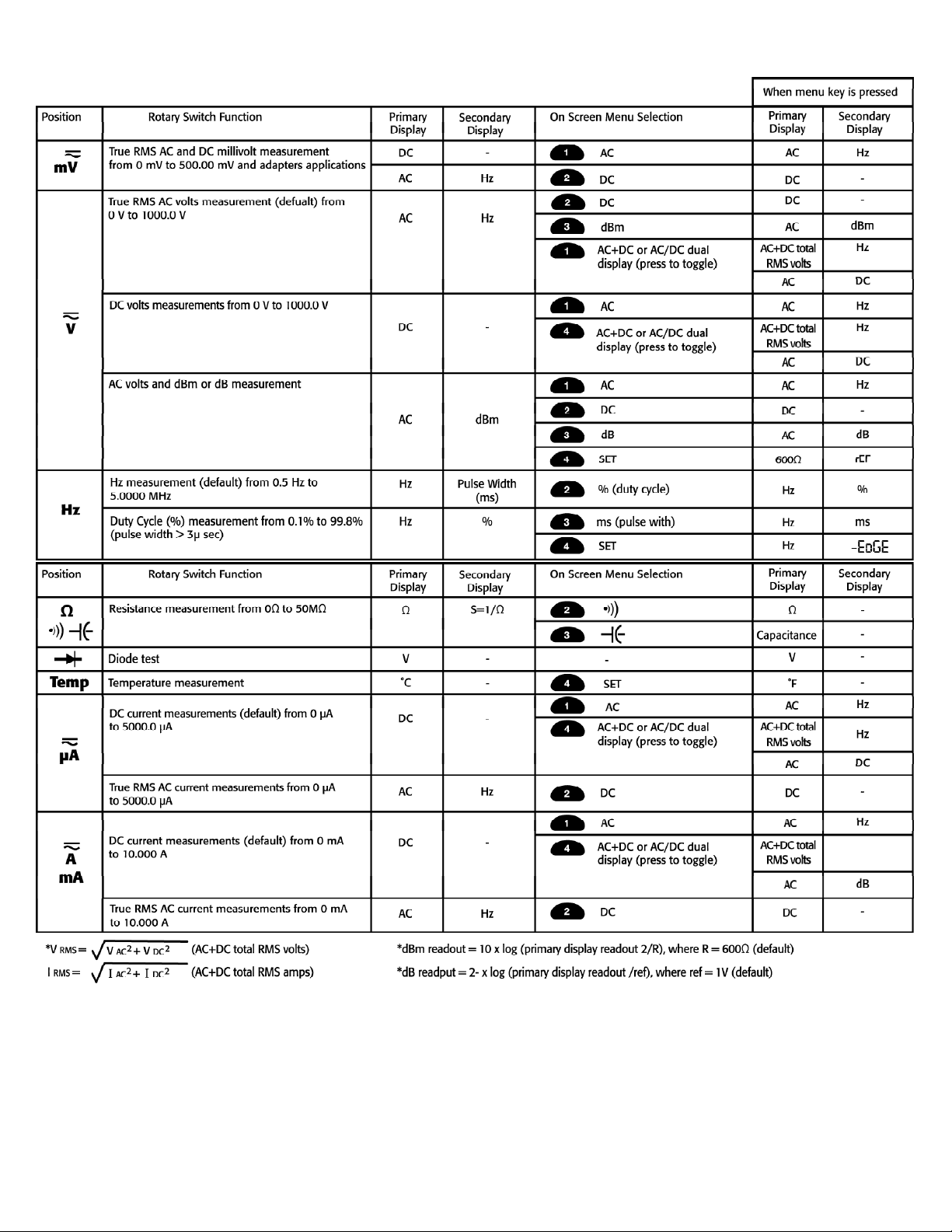
User-Friendly Rotary Switch Selections
DM397-MAN P. 3

Push-Buttons
RANGE: Use the “RANGE” push-button to manually select a range.
Press and hold the “RANGE” push-button for two seconds to return
the meter to auto range mode.
The meter is in auto range mode when the “AUTO” indicator is on.
The range and units are displayed on the LCD.
MIN/MAX: Press this button to scroll through the minimum,
maximum and average values. The minimum (MIN) reading is
displayed first and this mode calculates an average (AVG) of all
readings taken since the mode was activated. The meter beeps
when a new maximum or minimum reading is updated.
In the MIN/MAX mode, the primary display continues to show the
present measurement value.
Auto Power Off feature will be disabled automatically in this mode.
1mS Peak: Press this button momentarily to activate the 1mS peak
hold mode to capture transient voltage or current signal events as
short as 1mS with its display resolution of 5,000 counts. The LCD
displays the “1mS” and “MAX” indicators at the upper left corner
and - and “EXIT” indicators in the on screen menu selection. In this
mode the meter will display the captured maximum value. Press
the - menu key and the LCD will now display “1mS” and “MIN”
indicators and “+” and “EXIT” indicators on screen. In this mode
the meter will display the minimum captured value. Press the “+”
menu key to capture a maximum value again if desired. The meter
will beep when a new maximum or minimum reading is updated.
Press either the “1mS PEAK” push-button or the “EXIT” menu key
to exit the 1mS peak hold mode. Auto Power Off feature is disabled
in this mode.
REL ∆: Use this push-button to set the meter to relative (REL∆)
mode and make relative measurements. The reference value for the
REL∆ measurement can be a measured, or a programmed value. The
reference value appears in the secondary display and the difference
value appears in the primary display.
<REL∆ to a Measured Value> - When you take the measurement
and the meter settles on the value, press this button. Subsequent
readouts will then be a difference from this reference value to the
new reading. This is useful for very low resistance values to
eliminate test lead resistance, or when observing a change from
a stable reading.
< R EL∆ to a Programmed Value> - Set the meter to the measurement
function and range you want and then press the “REL∆“ push-button.
While the meter is in REL∆ mode, press the “MIN/M A X” push-button
then the setup menu appears. Use the on screen menu selection
buttons to edit the desired reference value and then press the menu
button “4” for “EXIT” .
For subsequent readouts the programmed reference value is
subtracted from the actual measurement. The programmed
reference value is lost when the meter is turned off.
To exit REL∆ mode, press the “REL∆” push-button.
HOLD: Press this button to turn the “HOLD” mode on or off. When
the hold mode is activated, the meter beeps, freezes the display and
displays the “HOLD” indicator on the LCD. Hold mode freezes the
display for later view.
Auto Hold - To activate “AUTO HOLD” mode, press the “HOLD”
push-button two times until “A” and “HOLD” indicators appear
on the LCD.
NOTE: This mode is not available for capacitance measurements.
In this mode, the display automatically freezes and the meter beeps
when the measurement reading is stabilized. The display value will
be updated when a new measurement value is stabilized.
This mode is very useful when it is impossible for you to press the
“HOLD” push-button or see the meter display while probing and
taking measurements.
MEM: Use the memory mode to store and recall measurement values.
Press the “MEM” button momentarily in order to activate the
memory mode. The display shows four menu selections: store, recall,
clear and exit.
STORE: Select “STORE” to store the held value in the next available
m e m o r y location. The memory location number momentarily shows on
the secondary display. If no memory locations are available, FUL L s h o w s
on the secondary display for two seconds and nothing is stored. You must
clear the memory locations using the “CL EA R” key in order to store the
held value.
RECALL: Select “RECALL” to review the stored value using the
menu key. The secondary display shows the value stored in that
location. Whenever you press “+” or “-” menu key, the next or
previous stored value will be shown in the primary display and
the secondary display momentarily shows the corresponding
memory location.
CLEAR: Select “CLEAR” to clear all the stored values. When you
press the “CLEAR” key, the meter will ask you with the display of
“You Sure” along with the on screen menu selections of “AC”
(stands for All Clear), “CLEAR” and “EXIT”. When you press the
“CLEAR” key, the displayed value in the primary display is erased.
When you press the “AC” key, all the stored values are erased and
the word “Done” shows on the display. Press “EXIT” to exit the
memory mode without erasing the stored values.
EXIT: Select “EXIT” to exit memory mode. You can also exit
memory mode by pressing “MEM” push-button or turning the
rotary dial position.
(Backlight): Press the “MEM” ( ) push-button until the
backlight is turned on or off.
DM397-MAN P. 4
 Loading...