

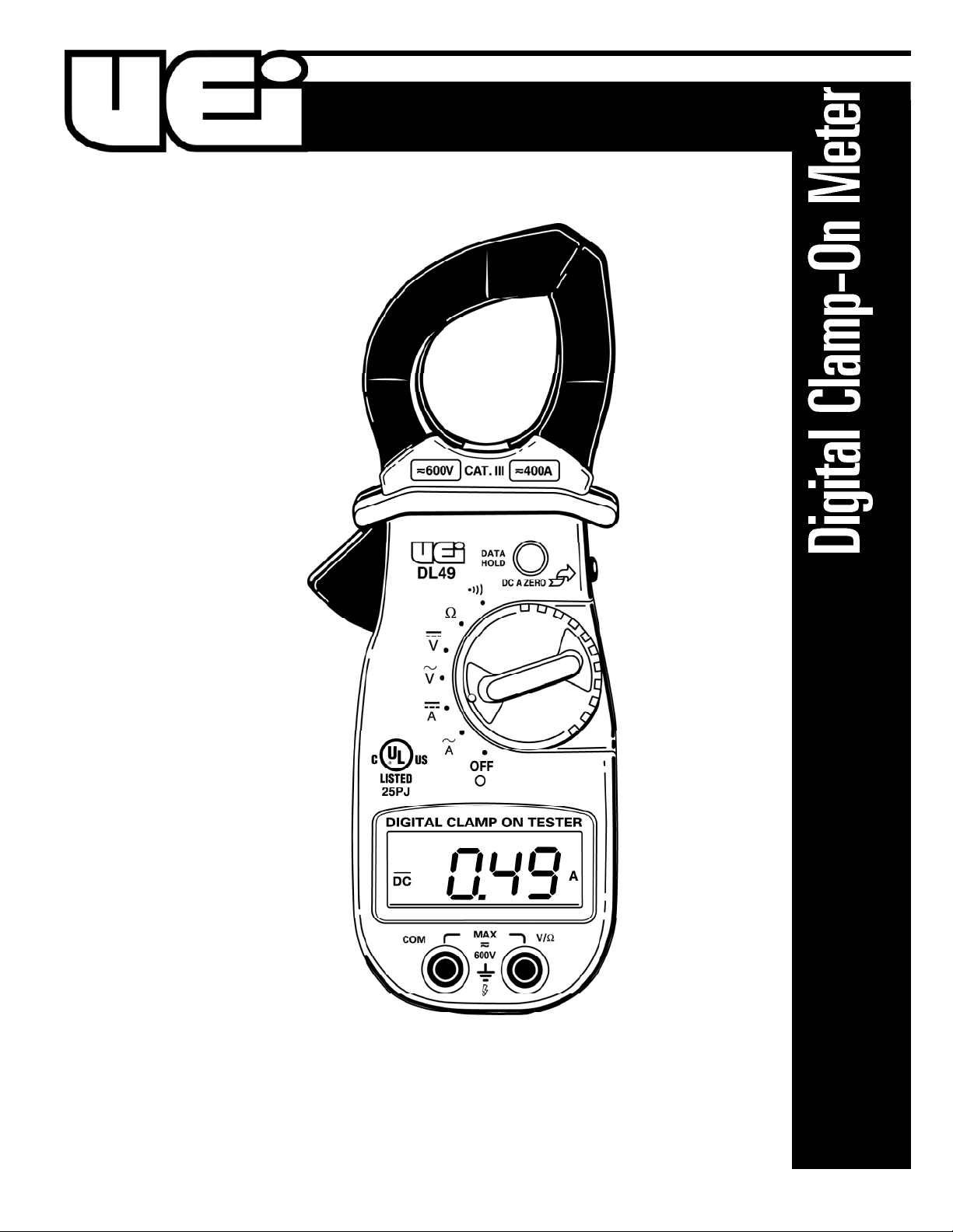
Universal Enterprise DL49 Installation Manual
1-800-547-5740 • Fax: (503) 643-6322
www.ueitest.com • email: info@ueitest.com
DL49
INSTRUCTION MANUAL
• If any of the following indications occur during testing, turn
off the power source to the circuit under test:
• Arcing
• Flame
• Smoke
• Extreme Heat
• Smell of Burning Materials
• Discoloration or Melting of Components
• Read the safety precautions associated with the equipment being
tested and seek assistance or advice when performing
unfamiliar tasks.
• Keep your fingers away from the test lead metal probe contacts
and bus-bars when making measurements. Always grip the
instrument and test-leads behind the hand guards (molded into
the probes).
• In the event of electrical shock, ALWAYS bring the victim to
the emergency room for evaluation, regardless of the victim’s
apparent recovery. Electrical shock can cause an unstable heart
rhythm that may need medical attention.
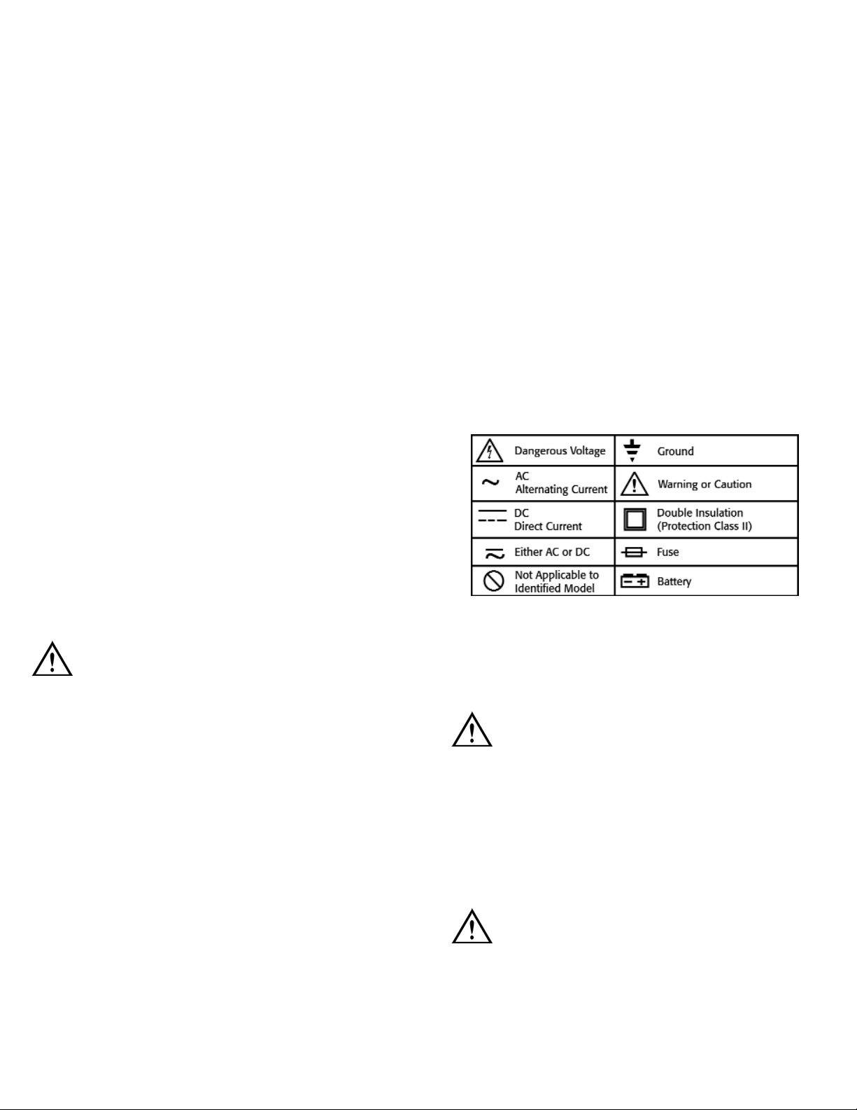
International Symbols
C o n t r ols and Indicators
1. C l a m p : Used to measure inductive AC and DC current.
Opens to 1 1/2” (40 mm).
CAUTION!
The clamp uses a high-tension spring to close the jaw. DO NOT allow
fingers or objects to become pinched in the base as jaw closes.
2. Conductor Alignment Marks: Used to aid in the visual
alignment of a conductor when measuring inductive ampera g e .
Greatest accura c y is achieved when the conductor inside the clamp
is centered at the intersection of these marks.
3. Hand Guard: Used as a point of reference for the operator’s safety.
WARNING!
Always keep your hands and fingers behind the hand guards when
measuring current on exposed conductors. Contact may result
in serious safety.
Introduction
The DL49 is a hand-held, battery powered, digital meter with clamp-on
current measuring ca p a b i l i t y. This instrument is ideal for anyone that
needs to make quick, accurate measurements of voltage, resistance, and
AC or DC inductive ampera g e .
Features include
• UL listed 3111-1
• Six measurement functions
1. AC inductive amps (to 400 amps)
2. DC inductive amps (to 400 amps)
3. AC Volts
4. DC Volts
5. Ohms
6. Continuity (with audible alert)
• Autoranging
• AC amperage peak-hold
• Data hold for volt, ohm, and amperage functions
• Low battery indicator
• Auto continuity
• Auto power off
• Rugged construction
• Surge protection
• Compact size for easy access to tight areas
Safety Notes
Before using this meter, read all safety information carefully. In
this manual the word "WARNING" is used to indicate conditions
or actions that may pose physical hazards to the user. The word
"CAUTION" is used to indicate conditions or actions that may
damage this instrument.
WARNING!
Exceeding the specified limits of this meter is dangerous and can
expose the user to serious or possibly fatal injury.
• DO NOT attempt to measure any voltage that exceeds 600 volts
with this meter - UEi offers numerous alternatives for measuring
high voltage and current
• Voltages above 60 volts DC or 25 volts AC may constitute a
serious shock hazard
• DO NOT attempt to use this meter if either the meter or the test
leads have been damaged. Send unit in for repair by a qualified
repair facility
• Test leads must be fully inserted prior to taking measurements
• Always turn off power to a circuit (or assembly) under test before
cutting, unsoldering or breaking the current path. Even small
amounts of current can be dangerous
• Always disconnect the live test lead before disconnecting the
common test lead from a circuit
• When measuring high voltage, disconnect the power source before
making test lead connections. Connect the test leads to the meter
first then to the circuit under test. Reapply power
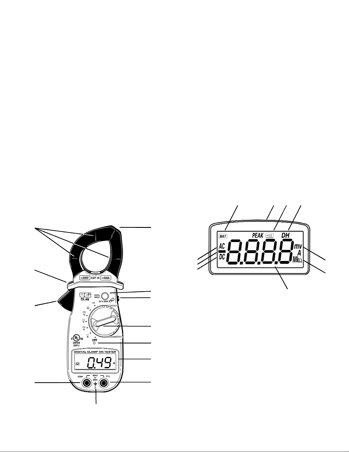
LCD Display Functional Description
1. Peak Hold: I n d i cates the meter is displaying the maximum inductive
AC current value recorded.
2. Continuity: I n d i cate s the meter is in the continuity measurement
mode and will sound a tone when measuring resistance below
approximately 50 ohms.
3. Data Hold: I n d i c ates the value displayed is held on screen
(the data hold button is pressed).
4. Low Battery Indicator: This symbol appears when the battery
needs replacement.
NOTE: A low battery will adversely affect accuracy.
5. AC: I n d i cat es that alternating current/voltage is being measured.
6. Minus: I n d i c ates the value measured has a negative polarity.
7. DC: I n d i c ates that direct current/voltage is being measured.
8. mVA: I n d i cates that millivolts (mV), volts (V), milliamps (mA) or
amps (A) is being displayed.
9. MKΩ: Indicates that Megohms, Kilohms, or ohms are
being displayed.
10. Numerical Value: Displays the total value of the units displayed.
Operating Instructions
Auto-Power Off
This instrument automatically shuts off after 30 minutes of inactivity. The
meter is considered active when there is a change of at least 10 digits
during this period (for example: the meter senses a change from 24.04
volts to 24.14 volts).
Autorange Resolution
This instrument automatically selects the range that gives you the best
resolution for the function and value measured. As the meter seeks the
appropriate range, the display may briefly display an overload (OFL)
indication or show quickly changing values until it stabilizes.
4. Data Hold Push-button: Freezes the value displayed on the
digital read-out.
5. Peak Hold Push-button: Used to capture the highest AC
inductive amp reading and to automatically zero (approximately) the
inductive DC amp readings.
6. Clamp Lever: Opens and closes current clamp jaw.
7. Rotary Function Switch: Used to power the meter on and off, or
to select one of the available measurement functions.
NOTE: Measure inductive AC and DC current using the clamp.
Measure volts AC and DC, resistance and continuity at the
test lead inputs.
8. Off Position: Turns the meter off. Always store your meter in the
off position. If the meter will not be used for a month or more,
remove the batteries.
9. Display: C o m m u n i c ates function, range, and value information to
the user.
10. Common Terminal: The black test lead is plugged into this
terminal to supply the ground or “low” reference for
all measurements.
11. Volt/Ohm (Ω) Terminal: The red lead is plugged into this
terminal. It is used for AC/DC volts, ohms, and continuity measurements.
12. Maximum Input Statements: M A X 600V indicates that a
m aximum of 600 Volts can be applied between the two terminals of
b e t ween earth ground and any terminal.
4
2
3
6
7
9
1
1
5
8
10
11
12
2 34
5
6
7
8
9
10
 Loading...