

Page 1
• Do not attempt to measure any voltage that exceeds the
category based rating of this meter
• Do not attempt to use this meter if either the meter or the test
leads have been damaged - Turn instrument in for repair at a
qualified repair facility
• Ensure meter leads are fully seated by making a quick
continuity check of the leads prior to making voltage
measurements
• Keep your fingers away from the test lead’s metal probe
contacts when making measurements - Always grip the leads
behind the finger guards molded into the probes
• Do not open the meter to replace batteries while the
probes are connected
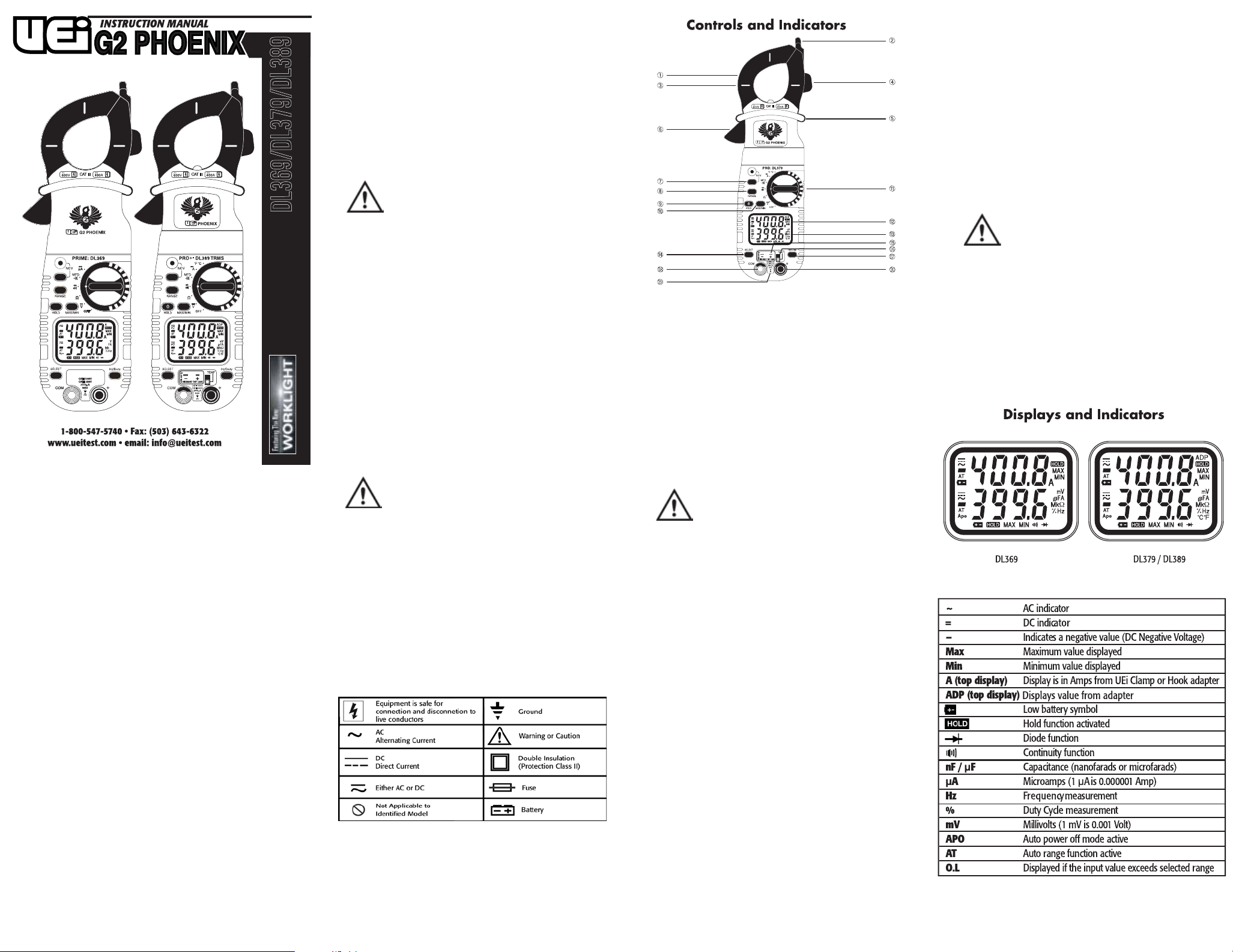
15. Temperature Input Jack: Input jack for k-type
thermocouple probe (DL379/DL389 only).
16. Temperature Switch: Move the Switch down to measure
temperature. NOTE: Test leads must be removed from input
jacks prior to operating the temperature function.
17. Hz/Duty Button: Used to scroll through Frequency or Duty
Cycle when in the AC Voltage measurement mode.
18. Common Terminal: The black test lead is plugged into this
terminal to supply the ground or “low” reference for
all measurements.
DL369/DL379/DL389
Introduction
The G2 Phoenix Series is a hand-held, battery powered digital multimeter
with clamp-on current measuring capability, back light and work
area light.
Features include
• 3-3/4 digit, count 4000 count LCD display
• Auto-ranging measurement with manual ranging capability
• MIN/MAX (Peak Hold) (all ranges except Frequency)
• Frequency/Duty Cycle/Data Hold
• Auto power off
• Dual display
• Built-in test lead storage
• EasyVue Backlit display & Worklight (DL379 & DL389)
• Detachable current probe with optional current hook adapter
for tight spaces (DL379 & DL389)
• Temperature (DL379 & DL389)
• Magnetic mount (DL379 & DL389)
• TRMS Measurement (DL389 only)
Safety Notes
Exceeding the specified limits of this meter is dangerous and can
expose the user to serious or possibly fatal injury.
• Voltages above 60 volts DC or 25 volts AC may constitute a
serious shock hazard
• Always turn off power to a circuit (or assembly) under test
before cutting, unsoldering, or breaking the current path Even small amounts of current can be dangerous
• Always disconnect the live test lead before disconnecting the
common test lead from a circuit
• In the event of electrical shock, ALWAYS bring the victim to the
emergency room for evaluation, regardless of the victim’s
apparent recovery - Electrical shock can cause an unstable
heart rhythm that may need medical attention
• If any of the following indications occur during testing, turn off
the power source to the circuit under test:
• Arcing
• Flame
• Smoke
• Extreme heat
• Smell of burning materials
• Discoloration or melting of components
WARNING!
WARNING!
Higher voltages and currents require greater awareness of physical
safety hazards. Before connecting the test leads; turn off the power
to the circuit under test; set the meter to the desired function and
range; connect the test leads to the meter first, then connect to the
circuit under test. Reapply power. If an erroneous reading is
observed, disconnect power immediately and recheck all settings
and connections.
This meter is designed for trade professionals who are familiar
with the hazards of their trade. Observe all recommended safety
procedures that include proper lock-out utilization and the user of
personal protective equipment that including safety glasses,
gloves and flame resistant clothing.
19. Category Max Indicator: Indicates maximum voltage for the
rated working category.
WARNING!
Do Not exceed 1000 volts DC or AC - RMS at either the
common or multifunction imput ports as measured from
earth ground.
1. Clamp: Measure inductive AC current. Opens to 1.25" (32 mm).
2. Wire Separation Tab/NCV sensor : Used to isolate an
individual wire from a bundle for testing.NCV sensor helps
detect live voltage.
3. Conductor Alignment Marks: Used to aid in the visual
alignment of a conductor when measuring inductive amperage.
Greatest accuracy is achieved when the conductor inside the
clamp is centered at the intersection of these marks.
4. Test Lead Holder: Used for hands-free use of one of the test
probes.
5. Hand Guard: Used as a point of reference for the operators
safety.
20. Multifunction Input Jack: Used for measuringAC/DC Volts,
Frequency or Duty Cycle, Resistance,Diode, Continuity and
Capacitance.
WARNING!
Always keep your hands and fingers behind the hand guards
when measuring current on exposed conductors. Contact may
result in serious injury.
6. Clamp Lever: Opens and closes current clamp jaw.
NOTE: The clamp uses a high tension spring to close the
jaw. Do not allow fingers or objects to become pinched in
the base as jaw closes
7. NCV Button: Activates non-contact voltage function
8. Range Button: Used to select range for upper and lower display.
9. HOLD/Backlight Button: Freezes display or activates display
backlight and work area light. (Backlit and work area light only
available on DL379/DL389)
10. MIN/MAX Button: Activates MIN/MAX capture function,
cycles through minimum value, maximum value. Press longer
than two seconds to return to current reading.
11. Rotary Function Switch:Turns meter on and is used to select
the range or function
Before using this meter, read all safety information carefully. In this
manual the word "WARNING" is used to indicate conditions or actions
that may pose physical hazards to the user. The word "CAUTION" is
used to indicate conditions or actions that may damage this
instrument.
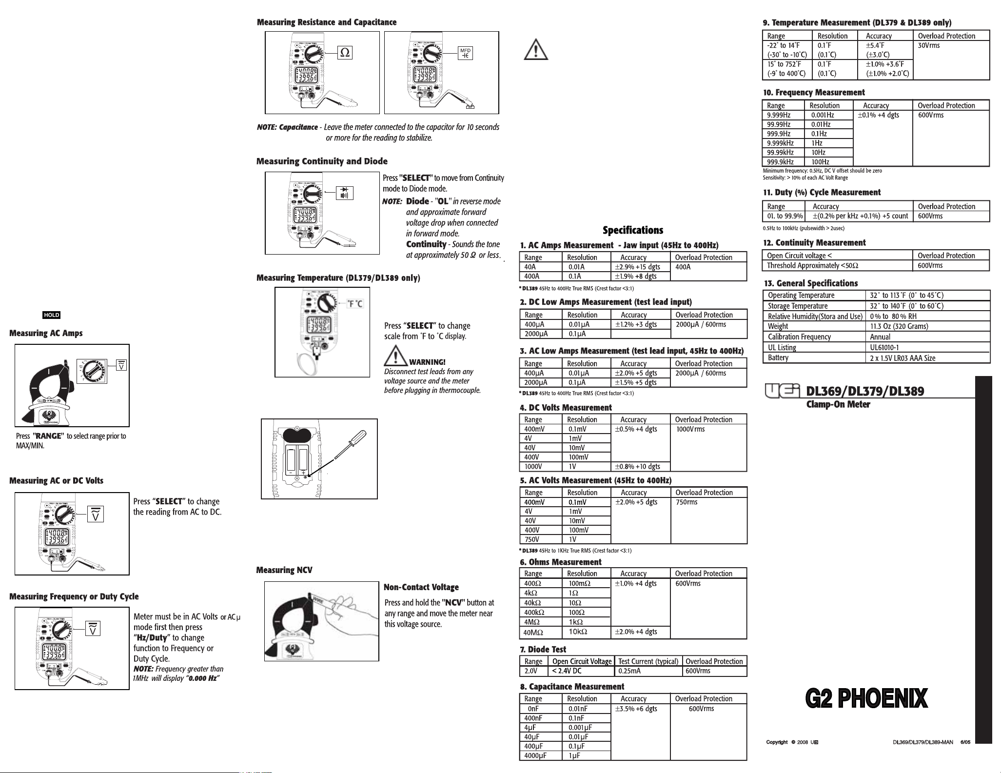
12. Upper Display : Used to display current when used with UEi
clamp or hook adapter. Displays output from other accessories
when connected to the UEi meter.
13. Lower Display: Used to display input to test lead jacks.
Includes AC/DC Volts, Frequency, Resistance, Diode,
Capacitance and AC/DC microamps (µA).
14. Select Button: Used to choose measurement mode from
selections with multiple options such as AC or DC volts, AC or
DC µA, Resistance, Diode, Capacitance or Continuity,
Temperature in ˚F or ˚C.
Page 2
Operating Instructions
Auto power off
After powering off, the meter will turn back on if you perform one of
the following; Change the range, move the position of the selector or
any other button is pressed. NOTE APO is disabled while in MIN/MAX
mode.
Back-light / work area light(DL379 / DL389 only)
Press the “HOLD” button longer than two seconds to activate the
backlight/work area light. The lights automatically turn off after 2
minutesto extend battery life.
NOTE: After activating worklight, press briefly to activate hold.
Auto / Manual Range
In auto range the meter will select the best range for the measured
value, and "AT" is displayed. Press the "RANGE" button to cycle
through available ranges. “AT” will not be on the display when locked
in a specific range. Press and hold ”RANGE” button to return to auto
range.
MIN/MAX mode
When using the MIN/MAX capture mode for Amps, it is recommended
that you first select the range of the expected maximum value. If this
is not done it will lock in the lowest range possible for the initial
measurement. If the maximum value exceeds this range the meter will
capture “O.L” as the maximum value.
Maintenance
Periodic Service
WARNING!
Repair and service of this instrument is to be performed by qualified
personnel only. Improper repair or service could result in physical
degradation of the meter. This could alter the protection from electrical
shock and personal injury this meter provides to the operator. Perform
only those maintenance tasks that you are qualified to do.
Cleaning
Periodically clean your meter’s case using a damp cloth. DO NOT use
abrasive, flammable liquids, cleaning solvents, or strong detergents as
they may damage the finish, impair safety, or affect the reliability of
the structural components.
Battery Replacement
Remove screws from battery compartment cover on back of meter
and remove cover. Replace batteries with fresh batteries paying
attention to polarity position. Replace cover and screws.
0.44V
Manual ranging will also provide a faster response to the input.
Data Hold
Press the “ “ button to activate. This will freeze the reading and
range in the display for your review.
• Select any function to power
the upper display.
• Press “MAX/MIN” to activate
Max capture, Min capture, or
normal display.
NOTE: Max capture is useful
for motor in rush current.
Temperature Adjustment
Slide temperature switch
down prior to connecting
probe.
Remove battery cover.
Place temperature probe in a
known standard. (Stirred crushed
ice in distilled water can be used for
32ºF)
Adjust potentiometer with a
fine tip standard screwdriver to
match the display to 32ºF.
NOTE: The adjustment for the
potentiometer is accessible
throughthe lower right access
port under the battery cover.
Limited Warranty
The DL369/DL379/DL389 is warranted to be free from defects in
materials and workmanship for a period of three years from the date of
purchase. If within the warranty period your instrument should become
inoperative from such defects, the unit will be repaired or replaced at
UEi’s option. This warranty covers normal use and does not cover
damage which occurs in shipment or failure which results from
alteration, tampering, accident, misuse, abuse, neglect or improper
maintenance. Batteries and consequential damage resulting from failed
batteries are not covered by warranty.
Any implied warranties, including but not limited to implied warranties
of merchantability and fitness for a particular purpose, are limited to the
express warranty. UEi shall not be liable for loss of use of the instrument
or other incidental or consequential damages, expenses, or economic
loss, or for any claim or claims for such damage, expenses or economic
loss. A purchase receipt or other proof of original purchase date will be
required before warranty repairs will be rendered. Instruments out of
warranty will be repaired (when repairable) for a service charge. Return
the unit postage paid and insured to:
NOTE If The backlight / worklight
is on, the worklight will turn off
during NCV tests.
Attaching/ Detaching Clamp Head
To detach clamp head first unplug all leads and probes. Firmly
grab clamp head and pull apart. When attaching a clamp head or
attachment, align heads and push together ensuring the
heads lock securely.
NOTE: Leaving clamp head or attachment plugged in will
drain battery.
1-800-547-5740 • FAX: (503) 643-6322
Service: (800) 308-7709
www.ueitest.com • Email: info@ueitest.com
This warranty gives you specific legal rights. You may also have other
rights which vary from state to state.
 Loading...