

Page 1
1-800-547-5740 • Fax: (503) 643-6322
www.ueitest.com • email: info@ueitest.com
DL259
INSTRUCTION MANUAL
Page 2
Introduction
The DL259 is a hand-held, battery powered digital TRMS multimeter
with clamp-on current measuring capability. Back light and work
area light.
Features include
• True RMS
• Work light and backlit display
• 400 Amps AC
• 1000 Volts Ac and DC
• Resistance to 40 Megohms
• Continuity
• Capacitance to 10,000 microfarods
• Temperature from -40˚ to 2498˚F
• 0.1 µA DC resolution for flame safeguard circuit testing
• Time-stamped record function
• Autoranging manual override
• MIN/MAX and data hold
• 1 1/3” jaw capacity
• Three year limited warranty
Safety Notes
This meter is designed for trade professionals who know the hazards
and safety practices associated with electrical measurement. Exceeding
the specified limits of this meter is dangerous and can expose the user
to serious or possibly fatal injury.
Before using this meter, read all safety information carefully. In this
manual the word "WARNING" is used to indicate conditions or actions
that may pose physical hazards to the user. The word "CAUTION" is
used to indicate conditions or actions that may damage this instrument.
WARNING!
Higher voltages and currents require greater awareness of physical
safety hazards. Before connecting the test leads; turn off the power
to the circuit under test; set the meter to the desired function and
range; connect the test leads to the meter first, then connect to the
circuit under test. Reapply power. If an erroneous reading is
observed, disconnect power immediately and recheck all settings
and connections.
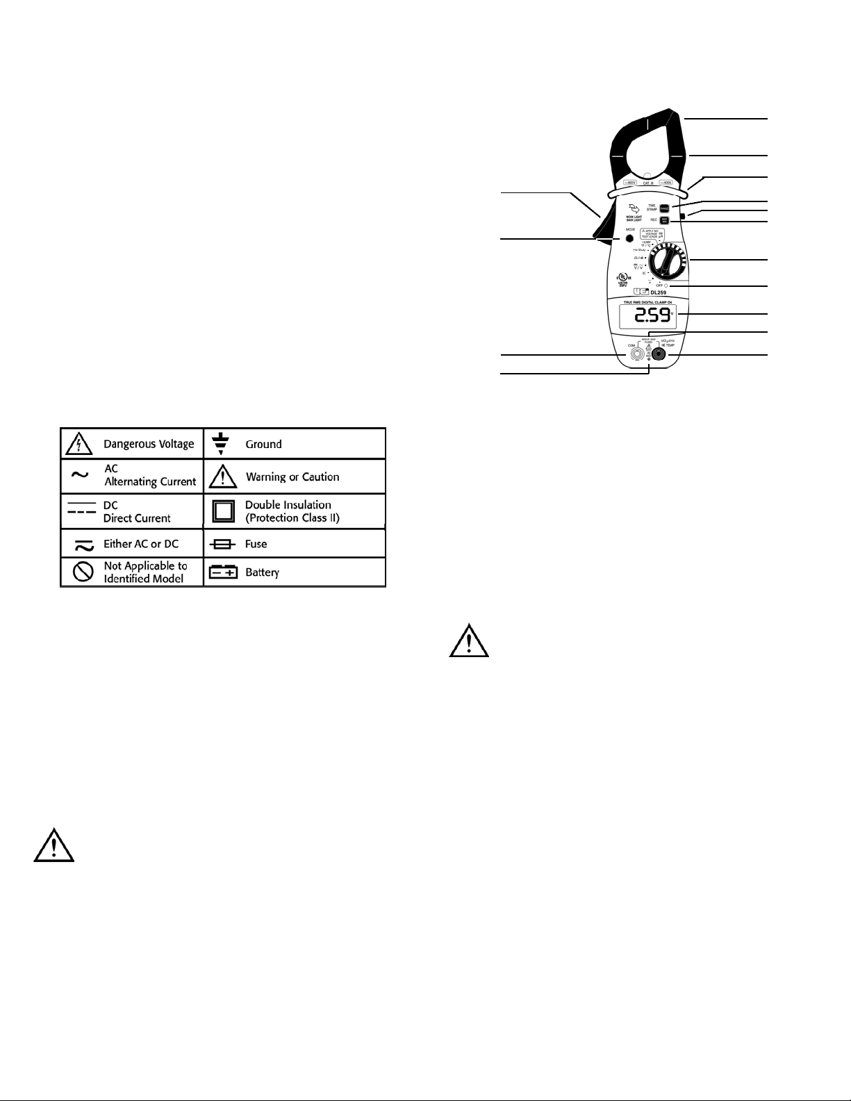
C o n t r ols and Indicators
1. Clamp: Measure inductive AC current. Opens to 1.25" (32 mm).
NOTE: The clamp uses a high tension spring to close the
jaw. Do not allow fingers or objects to become pinched in
the base as jaw closes.
2. Conductor Alignment Marks: Used to aid in the visual
alignment of a conductor when measuring inductive
amperage. Greatest accuracy is achieved when the
conductor inside the clamp is centered at the intersection
of these marks.
3. Hand Guard: Used as a point of reference for the
operators safety.
WARNING!
Always keep your hands and fingers behind the hand guards when
measuring current on exposed conductors. Contact may result in
serious injury.
4. Range and Time Stamp Push-button: Switches meter
from auto to manual ranging. Also initiates the time stamp
function when used in conjunction with MAX / MIN / R e c o r d i n g .
5. Work Light/Hold Push-button: Freezes the value displayed on
the digital read-out. This function does not work while recording is
in progress. Also turns on back light and work area light. Press for
2 seconds to activate the work light.
6. MAX/MIN Push-button: Use to cycle through recorded and
present values, and the time stamp function.
7. Clamp Lever: Opens and closes current clamp jaw.
8. Mode Push-button: Toggles the color-coded optional functions
indicated on the rotary function switch (AC to DC volts, ohms to
continuity and degrees centigrade to fahrenheit, frequency to
duty cycle).
DL259-MAN P. 1
1
2
3
4
5
6
9
10
11
12
15
7
8
13
14
Page 3

22. Indicates the meter is currently recording the maximum and
minimum values.
23. MIN: Indicates the meter is displaying the minimum
value recorded.
24.
•
)
)
)
: Indicates the meter is in the continuity measurement mode.
25. D.H.: Indicates the value displayed is held on screen
(the data hold button is pressed).
26. R.H.: Indicates the meter is in the manual ranging mode
(the Range button has been pressed).
27. Function and Units of Measurement:
28. OFL: This symbol appears when the input value exceeds
the meters selected range or overall specification.
Operating Instructions
Auto Power Off
The instrument automatically shuts off after 30 minutes of inactivity.
The meter is considered active when there is a change of at least 10
digits during the period (i.e., the meter senses a change from 24.04
volts to 24.14 volts)
To disable this function; press and hold the "MIN/MAX" or the
"RANGE" button while turning the meter on. This must be done to
record values for periods longer than 30 minutes.
Back-light / Work light
Press and hold the Data hold / back light button for two seconds. This
will activate the display back light and work area light for 30 seconds.
Pressing the “D/H” button again for two seconds will also turn it off.
9. Rotary Function Switch: Used to power the meter on and
off, or to select the available measurement functions:
• Measures inductive AC current using the clamp
• Measures capacitance at the test lead inputs
• Measures volts AC or DC Volts at the test lead inputs
• Measures resistance or continuity at the test lead inputs
• Measures Hz and Duty Cycle
• Measures temperature with the K-type thermocouple
and adapter plug at the test lead inputs
• Measures DC microamps using the test lead inputs
CAUTION!
When taking DC current and micro amp measurements, this meter
must be connected in SERIES with the circuit (or circuit element) under
test. NEVER CONNECT THE TEST LEADS ACROSS A VOLTAGE
SOURCE while the rotary switch is set to the microamps position. This
can cause damage to the circuit under test or this meter.
10. Off Position: Turns the meter off. Always store your meter in
the off position. If the meter will not be used for a month or
more, remove the batteries.
11. Display: Communicates function, range and value information
to the user. (See items 16 through 30)
12. 400 µA MAX FUSED: Indicates that the DC µA ranges are
fuse protected.
13. Common Terminal: The black test lead is plugged into this
terminal to supply the ground or “low” reference for
all measurements.
14. MAX 600V : Indicates that a maximum of 600 volts
can be applied between the two terminals or between earth
ground and any terminal.
WARNING!
DO NOT Exceed 600 volts DC or AC-RMS at either the common or
multifunctional input ports, as measured from earth ground in a CAT III
test environment, or 1000 volts in a CAT III test environment.
15. VΩ µA TE MP Terminal: The red lead is plugged
into this terminal. It is used for AC/DC volts, ohms, continuity,
microamps, diode, capacitance and temperature measurements.
The following describes the indicators displayed by the LCD.
16. this symbol appears when the battery needs replacement.
NOTE: A low battery will adversely affect accuracy.
17. AC: Indicates that alternating current/voltage is being measured.
18. Minus (—): Indicates the value measured has a
negative polarity.
19. DC: Indicates that direct current/voltage is being measured.
20. AT: Indicates the meter is in the autoranging mode.
21. MAX: Indicates the meter is displaying the maximum
value recorded.
BAT
R
Symbol Function or Value
°C Degrees Centigrade
°F Degrees Fahrenheit
µF Micro Farads
mV Millivolts
V Volts
µA Micro Amps (Test Leads)
A Amps (Inductive Clamp)
M Mega (Value x 1,000,000)
K Kilo (Value x 1,000)
Ω Ohms (Resistance Value)
Hz Hertz
% Duty Cycle
DL259-MAN P. 2
21 22 23 24 25 26
27
28
16
30
17
18
19
20
Page 4

Auto / Manual Range
In auto range the meter will select the best range for the measured
value, and "AT" indicate in the lower left of the display. Press "Range"
to cycle through available ranges for each function. "AT" will not be on
the display when locked in a specific range.
When using the record mode it is recommended that you select the
range first. The record function will lock the meter into the range first
measured, and could indicate over-range (OFL ) for maximum or
minimum values outside this range. Manual range will also provide a
faster response to inputs.
Data Hold
Press data hold “D/H” button to activate. This will freeze the
reading and range in the display for your review.
Record and Time Stamp
The meter will record minimum, maximum and elapsed time for all
functions except capacitance. To activate and review recorded events
see figure 1.
Figure 1
Capacitance
NOTE: Some large capacitors take approximately 10 seconds to settle
on a value.
WARNING!
Capacitors should be completely discharged prior to testing.
Measure AC or DC Volts
Measuring Resistance and continuity
Measuring Frequency / Duty Cycle
Measuring Temperature
Note: Press "Mode" to select ˚C or ˚F.
Temperature adjustment
The DL259 temperature can be adjusted to a known set point. The
best method is in a stirred mix of crushed ice and water. Insert
thermocouple in meter, select temperature, then measure the ice mix.
Adjustment for setting to 32˚F is inside battery compartment. (See
maintenance section)
Measuring µA
Press
"Mode"
to select DC
AC
DC
Press
"Mode"
Press
"Mode"
Press
"Mode"
to Select C˚
DL259-MAN P. 3
Continuity
Resistance
(Break circuit to
measure µA)
Page 5

Maintenance
Battery and fuse replacement
Battery – 9V NEDA 1604 or 6LR61
Fuse – AF155, 500mA / 660V
Specifications
1. AC amps Measurement (45Hz-400Hz
)
Crest Factor < 3 : 1
2. DC Low amps Measurement
3. DC Volts Measurement
4. AC Volts Measurement (45Hz-2kHz)
Crest Factor < 3 : 1
5. Ohms Measurement
(Remove screw)
Temperature
adjustment
6. Capacitance Measurement
7. Temperature Measurement
8. Frequency Measurement
9. Continuity Measurement
10. % Duty Cycle
Probe: The probes are UL listed to 1000V, 10A, CAT III and are
double insulated.
Physical Specifications
Range
4V
40V
400V
1000V
Resolution
1mV
10mV
100mV
1V
Accuracy
±1.9%+3dgts
Overload Protection
600V RMS
Range
400
4k
40k
400k
4M
40M
Resolution
100m
1
10
100
1k
10k
Accuracy
±0.9%+3dgts
±1.2%+3dgts
±1.5%+5dgts
Overload Protection
600V
Range
1µF
10µF
100µF
1000µF
10000µF
Resolution
0.001µF
0.01µF
0.1µF
1µF
1µF
Accuracy
±1.7%+5dgts
±2.5%+15dgts
±15%+100dgts
Overload Protection
600V
Range
999.9Hz
9.999Hz
99.99Hz
Resolution
0.1Hz
1Hz
10Hz
Accuracy
±0.05%+2d
Overload
Protection
600V
Open circuit voltage <2.7V
Threshold Approx: <50
Overload Protection
600V
DL259-MAN P. 4
Range R e s o l u t i o n Accuracy Overload Protection
-40˚ to 68˚F 0.1˚ ±5.4˚F 600V
(-40˚ to 20˚C) (0.1˚) ±(3.0˚C)
68˚ to 400˚F 0.1˚ ±1.0% +3.6˚F
(20˚ to 400˚C) (0.1˚) (±1.0% +2.0˚C)
400˚ to 2,498˚F 1˚ ±3% of reading
(400˚ to 1.370˚C) (1˚)
Range R e s o l u t i o n Accuracy Overload Protection
0.0 - 99.9% 0 .1 % ±0.2% per kHz +0.1 % 6 0 0 V
Operating temperature 32˚ to 104˚F (0˚ to 40˚C)
Storage temperature -4˚ to 140˚F (-20˚ to 60˚C)
Relative humidity Maximum relative humidity 80% for
temperatures up to 31˚C decreasing
linearly to 50% relative humidity at 40˚C
Altitude Operating - up to 2000 m
Storage - 10000 m
Pollution degree 2
Installation category CAT III
Certifications UL & cUL standard UL 3111-1 listed
Range
40A
400A
Resolution
0.01A
0.1A
Accuracy
±3.0%+20dgts
±2.0%+5dgts
Overload Protection
400A Continuous
Range
40µA
400µA
Resolution
0.01µA
0.1µA
Accuracy
±1.0%+5dgts
±1.5%+2dgts
Overload Protection
400µA/600V
Range
4V
40V
400V
1000V
Resolution
1mV
10mV
100mV
1V
Accuracy
±0.9%+2dgts
Overload Protection
600V RMS
Page 6

Limited Warranty
The DL259 is warranted to be free from defects in materials and workmanship for a period
of three years from the date of purchase. If within the warra n ty period your instrument
should become inoperative from such defects, the unit will be repaired or replaced at UE i ’ s
option. This warra n ty covers normal use and does not cover damage which occurs in
shipment or failure which results from alteration, tampering, accident, misuse, abuse,
neglect or improper maintenance. Batteries and consequential damage resulting from failed
batteries are not covered by warra n ty.
Any implied warranties, including but not limited to implied warranties of merchantability
and fitness for a particular purpose, are limited to the express warranty. UEi shall not
be liable for loss of use of the instrument or other incidental or consequential damages,
expenses, or economic loss, or for any claim or claims for such damage, expenses or
economic loss. A purchase receipt or other proof of original purchase date will be required
before warra n ty repairs will be rendered. Instruments out of warra n ty will be repaired
(when repairable) for a service charge. Return the unit postage paid and insured to:
1-800-547-5740 • FAX: (503) 643-6322
www.ueitest.com • Email: info@ueitest.com
This warranty gives you specific legal rights. You may also have other rights which vary from
state to state.
DL259
True RMS Clamp-On Multimeter
Copyright © 2007 UEi DL259-MAN 1/07
PLEASE
RECYCLE
 Loading...